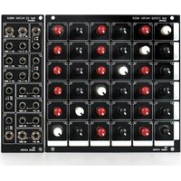
ADDAC814 - Audio Mixer ADDAC System - Free user manual and instructions
Find the device manual for free ADDAC814 ADDAC System in PDF.


| Product Type | Eurorack Module |
| Brand | ADDAC System |
| Model | ADDAC814 |
| Module Width | 8 HP |
| Depth | 30 mm |
| Weight | 120 g |
| Power Supply | +12V / -12V via Eurorack bus board |
| Current Consumption | +12V: 80 mA, -12V: 20 mA |
| Main Functions | Quad CV processor with mixing, attenuation, and offset |
| Inputs | 4 CV inputs (0-10V) |
| Outputs | 4 CV outputs (0-10V) |
| Controls | 4 attenuverter knobs, 4 offset knobs, 4 input switches |
| Construction | PCB and aluminum faceplate |
| Safety | Reverse power protection; do not exceed rated voltage |
| Maintenance & Cleaning | Wipe with dry cloth; avoid liquids |
| Spare Parts & Repairability | Contact ADDAC System for replacement knobs or PCBs |
| Warranty | 2 years limited |
| Compatibility | Eurorack case with sufficient power |
Frequently Asked Questions - ADDAC814 ADDAC System
User questions about ADDAC814 ADDAC System
0 question about this device. Answer the ones you know or ask your own.
Ask a new question about this device
Download the instructions for your Audio Mixer in PDF format for free! Find your manual ADDAC814 - ADDAC System and take your electronic device back in hand. On this page are published all the documents necessary for the use of your device. ADDAC814 by ADDAC System.
USER MANUAL ADDAC814 ADDAC System
Instruments for Sonic Expression
Est.2009
INTRODUCING
ADDAC814
6x6 STEREO
MATRIX MIXER

USER'S GUIDE . REV01
October.2024
ADDAC
System
From Portugal with Love!
WELCOME
We're pleased to announce our take on matrix mixers, a 6x6 stereo matrix easily expandable to larger configurations.
Matrix mixers may need some time to get used to but they are very much self explanatory, each knob controls the volume of a matrix point routing the respective input to the desired output.
The flexibility of a matrix mixer is far superior to a standard mixer, the possibility to route any input to any single or multiple outputs allow for very complex chains, combining parallel and series processing while easily reconfigurable without any extra patching.
All Inputs Left channels are normalled to the Right Inputs.
Blank areas on the left and bottom edges of the panel allow for the user to write all the inputs and outputs sources that each channel is connected to.
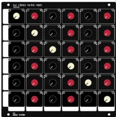
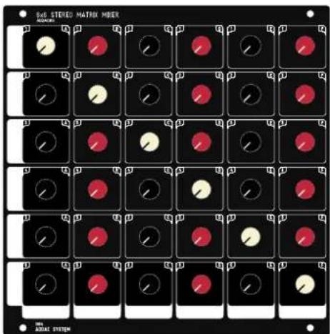
Different colored knobs for faster visual recalling: Black for A,C,E Outputs
Dark Red for B,D,F Outputs
Cream knobs for potential feedback diagonal: 1A, 2B, 3C, 4D, 5E, 6F.
DC coupled circuitry, can be used to mix both audio or cv signals.
Jumpers on the back of both modules allow the user to set each channel independently to Line or Synth Level, making it easier to integrate with external sources, sound processors or guitar pedals.
INTERNAL CONNECTIONS
The control and input modules are connected via a large 36 wire ribbon cable, only the control module needs to be connected to the Busboard.
Extra IDC sockets are used for connecting larger configurations like 12x12 or 18x18.
Other configurations are also possible: 6x12, 12x6, 18x6, etc...
Up to 12x12 all ribbon cables are provided, for larger matrixes custom ones will be necessary. contact us directly if planning to go BIG.
25HP 8HP


POWER RAILS RIBBON CABLE (Red Stripe Down)
B INS/OUTS RIBBON CABLE (2x17 Connectors)


Jumpers set the Output level of each channel:
No jumper · Synth level
With jumper = Line level
OUTPUTS JUMPERS
INPUTS JUMPERS
FEEDBACK
Feedback diagonal
This diagonal in matrix mixers routes the input X to the same X output. Depending on what is connected in those Ins/Outs it has the potential to generate feedbacks. For ex: if we plug a VCO into input 1 and use the output A as the mixer output then when raising the level of input 1 to output A this will simply act as a volume control of the VCO into the output. If we add a Filter in In 2/Out B, patching the output of a Filter module into input 2 and the Matrix output B to the Filter input. Then we can route the VCO through the Filter using the 1B Knob and forward the filter output to the master output using the 2A Knob.
In this setup whenever we raise the level of knob 2B we'll be routing the output of the Filter module into it's input generating a feedback in the Filter module (similar as increasing the filter's resonance). This can be used as a feature but also requires attention as it can lead to a drastic result.
We decided to use a different color for these knobs to highlight these special cases.


flowchart
graph TD
    A["6x5 TEREO MATRIX MIXER"] --> B["FILTER"]
    B --> C["FILTER OUTPUT"]
    C --> D["MAX ADDAC SYSTEM"]
    D --> E["MASTER OUTPUT"]
    D --> F["FILTER"]
    G["VCO OUTPUT"] --> H["STEREO MIXER+"]
    H --> I["DUAL FILTER ARCHEDS"]
    I --> J["DUAL MEND STIPS"]
    J --> K["OUTOFF OUTOFF REQUISANCE"]
    K --> L["OUT OF ATTENUATION"]
    L --> M["OUT OF ATTENUATION"]
    M --> N["OUT OF ATTENUATION"]
    N --> O["OUT OF ATTENUATION"]
    O --> P["OUT OF ATTENUATION"]
    P --> Q["OUT OF ATTENUATION"]
    Q --> R["OUT OF ATTENUATION"]
    R --> S["OUT OF ATTENUATION"]
    S --> T["OUT OF ATTENUATION"]
    T --> U["OUT OF ATTENUATION"]
    U --> V["OUT OF ATTENUATION"]
    V --> W["OUT OF ATTENUATION"]
    W --> X["OUT OF ATTENUATION"]
    X --> Y["OUT OF ATTENUATION"]
    Y --> Z["OUT OF ATTENUATION"]
    Z --> AA["OUT OF ATTENUATION"]
    AA --> AB["OUT OF ATTENUATION"]
    AB --> AC["OUT OF ATTENUATION"]
    AC --> AD["OUT OF ATTENUATION"]
    AD --> AE["OUT OF ATTENUATION"]
    AE --> AF["OUT OF ATTENUATION"]
    AF --> AG["OUT OF ATTENUATION"]
    AG --> AH["OUT OF ATTENUATION"]
    AH --> AI["OUT OF ATTENUATION"]
    AI --> AJ["OUT OF ATTENUATION"]
    AJ --> AK["OUT OF ATTENUATION"]
    AK --> AL["OUT OF ATTENUATION"]
    AL --> AM["OUT OF ATTENUATION"]
    AM --> AN["OUT OF ATTENUATION"]
    AN --> AO["OUT OF ATTENUATION"]
    AO --> AP["OUT OF ATTENUATION"]
    AP --> AQ["OUT OF ATTENUATION"]
    AQ --> AR["OUT OF ATTENUATION"]
    AR --> AS["OUT OF ATTENUATION"]
    AS --> AT["OUT OF ATTENUATION"]
    AT --> AU["OUT OF ATTENUATION"]
    AU --> AV["OUT OF ATTENUATION"]
    AV --> AW["OUT OF ATTENUATION"]
    AW --> AX["OUT OF ATTENUATION"]
    AX --> AY["OUT OF ATTENUATION"]
SIGNAL FLOW DIAGRAM

flowchart
graph TD
    subgraph Inputs
        direction TB
        INPUT1["INPUT 1 LEFT"] --> INPUT2["INPUT 2 LEVEL > TO OUTPUT A"]
        INPUT2 --> INPUT3["INPUT 3 LEVEL > TO OUTPUT B"]
        INPUT3 --> INPUT4["INPUT 4 LEVEL > TO OUTPUT C"]
        INPUT4 --> INPUT5["INPUT 5 LEVEL > TO OUTPUT D"]
        INPUT5 --> INPUT6["INPUT 6 LEVEL > TO OUTPUT E"]
    end

    subgraph Outputs
        direction TB
        INPUT1 --> OUTPUTA["OUTPUT A SIERED MIX"]
        INPUT2 --> OUTPUTB["OUTPUT B SIERED MIX"]
        INPUT3 --> OUTPUTC["OUTPUT C SIERED MIX"]
        INPUT4 --> OUTPUTD["OUTPUT D SIERED MIX"]
        INPUT5 --> OUTPUTE["OUTPUT E SIERED MIX"]
        INPUT6 --> OUTPUTF["OUTPUT F SIERED MIX"]
    end

    INPUT1 --> INPUT2
    INPUT2 --> INPUT3
    INPUT3 --> INPUT4
    INPUT4 --> INPUT5
    INPUT5 --> INPUT6
    INPUT6 --> OUTPUTA
    INPUT6 --> OUTPUTB
    INPUT6 --> OUTPUTC
    INPUT6 --> OUTPUTD
    INPUT6 --> OUTPUTE
    INPUT6 --> OUTPUTF
    INPUT7["INPUT 1 LEFT"] --> INPUT2
    INPUT7 --> INPUT3
    INPUT3 --> INPUT4
    INPUT4 --> INPUT5
    INPUT5 --> INPUT6
    INPUT6 --> OUTPUTA
    INPUT6 --> OUTPUTB
    INPUT6 --> OUTPUTC
    INPUT6 --> OUTPUTD
    INPUT6 --> OUTPUTE
    INPUT7 --> OUTPUTF
    INPUT8["INPUT 1 LEFT"] --> INPUT2
    INPUT8 --> INPUT3
    INPUT3 --> INPUT4
    INPUT4 --> INPUT5
    INPUT5 --> INPUT6
    INPUT6 --> OUTPUTA
    INPUT6 --> OUTPUTB
    INPUT6 --> OUTPUTC
    INPUT6 --> OUTPUTD
    INPUT6 --> OUTPUTE
    INPUT7 --> OUTPUTF
    INPUT8 --> OUTPUTF
    INPUT9["INPUT 1 LEFT"] --> INPUT2
    INPUT9 --> INPUT3
    INPUT3 --> INPUT4
    INPUT4 --> INPUT5
    INPUT5 --> INPUT6
    INPUT6 --> OUTPUTA
    INPUT6 --> OUTPUTB
    INPUT6 --> OUTPUTC
    INPUT6 --> OUTPUTD
    INPUT6 --> OUTPUTE
    INPUT7 --> OUTPUTF
    INPUT8 --> OUTPUTF
    INPUT9 --> OUTPUTF

    style Inputs fill:#f9f,stroke:#333,stroke-width:2px
    style Outputs fill:#ccf,stroke:#333,stroke-width:2px
ROUTING EXAMPLE
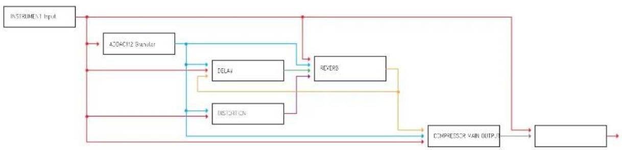
This example shows the potential for complex chains with both parallel and series processing as well as some feedback action on a Delay >Reverb chain.

flowchart
graph TD
    A["ADDAC112 Granular"] --> B["ADAC112 D"]
    C["DELAY"] --> D["ALAB REVERB"]
    E["REVERB"] --> F["DISTORTION"]
    G["COMPRESSOR"] --> H["INSTRUMENT INPUT"]
    I["STEREO MIXER+"] --> J["OUT A LEFT OUT A RED"]
    J --> K["OUT B LEFT OUT B RED"]
    L["COMPRESSOR"] --> M["OUT C LEFT OUT C RED"]
    N["INSTRUMENT INPUT"] --> O["OUT D LEFT OUT D RED"]
    P["ADAC112 D"] --> Q["EU REVERB DISTORTION COMPRESS OUTPUT"]
    R["PREVIER"] --> S["DISTORTION"]
    T["COMPRESSOR"] --> U["COMPRESSOR"]
    V["MAIN OUTPUT"] --> W["MAIN OUTPUT"]
Routing Diagram
flowchart
graph TD
    A["INSTRUMENT Input"] --> B["A304C112 Granular"]
    B --> C["DELAY"]
    B --> D["DISTINATION"]
    C --> E["REVERB"]
    D --> F["COMPRESSOR VAIN OUTPUT"]
    E --> F
    F --> G["Output"]
    C --> H["Signal Path"]
    D --> I["Signal Path"]
    H --> B
    I --> B
OTHER CONFIGURATIONS
EXPANDING THE MATRIX
Expanding to larger matrixes is possible using the Expansion module, below you can see the differences between the modules and their connections.
Depending on the desired configuration the user will require different modules as described in the next pages.
ADDAC814 is sold as a pair: ADDAC814A + ADDAC814B
ADDAC814A & ADDAC814C can be bought individually as expansions.
ADDAC814
ADDAC814A
INS & OUTS
ADDAC814B
MAIN CONTROLS

ADDAC814C
EXPANSION CONTROLS
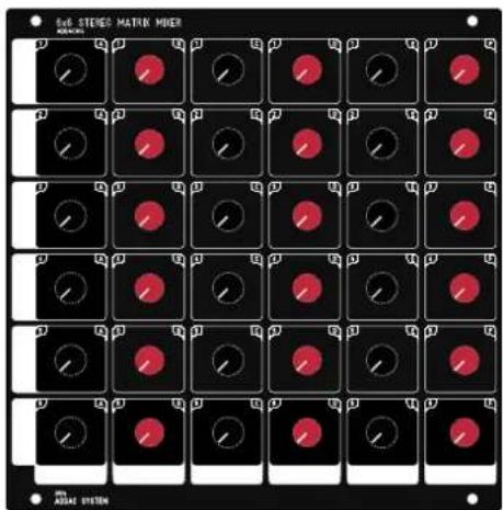
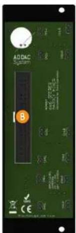
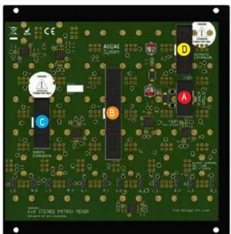

INS & OUTS MAIN CONTROLS
EXPANSION CONTROLS
A POWER RAILS RIBBON CABLE
B INS/OUTS RIBBON CABLE (2x17 Connectors)
C EXPANSION RIBBON CABLE (2x8 Connectors)
D EXPANSION RIBBON CABLE (2x8 Connectors)
OTHER CONFIGURATIONS
12x6 Configuration
With an ADDAC814 + an Expander Set (ADDAC814A + ADDAC814C) one can expand the matrix to a 12x6 configuration. This will use 2 rows of your frame and take a 33HP space in each. In the 12x6 configuration the second jack panel outputs are not used.
ADDAC814
INPUTS 1 to 6
OUTPUTS 1 to 6


INPUTS 7 to 12
OUTPUTS UNUSED
ADDAC814CADDAC814A

POWER RAILS RIBBON CABLE

INS/OUTS RIBBON CABLE (2x17 Connectors)

Vertical CONNECTIONBIBBOM CABLE (2x8 Connectors)
ADDAC814 EXPANDER SET
OTHER CONFIGURATIONS
6x12 Configuration
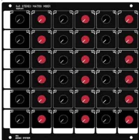
With two ADDAC814 one can expand the matrix to a 6x12 configuration.
This will take an overall of 66HP.
In this configuration the second jack panel inputs are not used.
ADDAC814 ADDAC814 (with no cream knobs)
:INPUTS 1 to 6
OUTPUTS 1 to 6
INPUTS UNUSED:
OUTPUTS 7 to 12
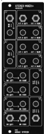


A POWER RAILS RIBBON CABLE
B INS/OUTS RIBBON CABLE (2x17 Connectors)
C or Horizontal CONNECTION BIBB ON CABLE (2x8 Connectors)
OTHER CONFIGURATIONS
12x12 Configuration
With two sets of ADDAC814 plus a pair of ADDAC814C one can expand the matrix to a 12x12 configuration. This will use 2 rows of your frame and take a 58HP space in each.


POWER RAILS RIBBON CABLE

INS/OUTS RIBBON CABLE (2x17 Connectors)

Vertical CONNECTION RIBBON CABLE (2x8 Connectors)

Horizontal CONNECTION RIBBON CABLE (2x8 Connectors)
OTHER CONFIGURATIONS
18x18 Configuration
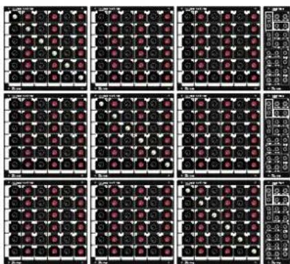
With 3 sets of ADDAC814 plus 6 ADDAC814C one can grow the matrix to a 18x18 configuration.
This will take an overall of 83HP in each 3 rows.
Custom ribbon cables will be necessary. contact us directly if planning to go this BIG.


POWER RAILS RIBBON CABLE

INS/OUTS RIBBON CABLE (2x17 Connectors)

Vertical CONNECTION RIBBON CABLE (2x8 Connectors)

Horizontal CONNECTION RIBBON CABLE (2x8 Connectors)
For feedback, comments or problems please contact us at: addac@addacsystem.com
- INTRODUCING
- ADDAC814
- 6x6 STEREO
- MATRIX MIXER
- WELCOME
- INTERNAL CONNECTIONS
- FEEDBACK
- Feedback diagonal
- SIGNAL FLOW DIAGRAM
- ROUTING EXAMPLE
- OTHER CONFIGURATIONS
- EXPANDING THE MATRIX
- 12x6 Configuration
- ADDAC814CADDAC814A
- 6x12 Configuration
- ADDAC814 ADDAC814 (with no cream knobs)
- 12x12 Configuration
- 18x18 Configuration
Brand : ADDAC System
Model : ADDAC814
Category : Audio Mixer