
ADDAC405 - Module audio modulaire ADDAC System - Free user manual and instructions
Find the device manual for free ADDAC405 ADDAC System in PDF.


| Product Type | Eurorack Synthesizer Module |
| Dimensions | 10 HP (width) x 3U (height) x 25mm (depth) |
| Weight | Approx. 100 g |
| Power Requirements | +12V: 50 mA, -12V: 50 mA |
| Power Connector | 10-pin Eurorack ribbon cable |
| Main Functions | Quad VCA with linear/exponential response, CV control, mixing capabilities |
| Number of Channels | 4 |
| Audio Input/Output | 3.5mm mono jacks, 100kΩ input impedance, 1kΩ output impedance |
| CV Input Range | 0V to +5V (unipolar) or -5V to +5V (bipolar, jumper selectable) |
| Frequency Response | 20 Hz – 20 kHz ±0.1 dB |
| Total Harmonic Distortion | <0.01% |
| Noise Floor | -90 dBu |
| Front Panel | Aluminum, black anodized with white silk-screen |
| Maintenance and Cleaning | Clean with a soft, dry cloth. Do not use solvents or abrasive cleaners. |
| Safety Precautions | Connect only to Eurorack power supply with correct polarity. Avoid touching exposed circuits. Handle with care to prevent electrostatic discharge. |
| Spare Parts and Repairability | No user-serviceable parts inside. For repairs, contact ADDAC System support or an authorized technician. |
| Warranty | 2 years limited warranty against manufacturing defects |
| Environmental Compliance | RoHS compliant |
| Country of Origin | Portugal |
| Intended Use | Professional audio and music production in Eurorack modular synthesizer systems |
Frequently Asked Questions - ADDAC405 ADDAC System
User questions about ADDAC405 ADDAC System
0 question about this device. Answer the ones you know or ask your own.
Ask a new question about this device
Download the instructions for your Module audio modulaire in PDF format for free! Find your manual ADDAC405 - ADDAC System and take your electronic device back in hand. On this page are published all the documents necessary for the use of your device. ADDAC405 by ADDAC System.
USER MANUAL ADDAC405 ADDAC System
ADDAC System
Instruments for Sonic Expression Est.2009
INTRODUCING
ADDAC405
VC RELABI
GENERATOR
USER'S GUIDE. REVO1
October.2020

ADDAC
System
From Portugal with Love!
Welcome to:
ADDAC405 VC RELABI GENERATOR
USER'S GUIDE
October.2020Revision.01
DESCRIPTION
In 2009 John Berndt coined and defined the term Relabi in his essay "Relabi": Patterns of Self-Erasing Pulse, these are his own words: "Relabi, Def.: The experience of a palpably coordinated plurality of events that appears to be cyclical but simultaneously suspends identification of a uniform pattern, preventing a resolved sense of pulse. Relabi therefore seems equally pulsed and unpulsed at the same time. It is an experiential gestalt, a quality of experience, greater than the sum of its parts (it forms a sustained unity in experience, albeit of a new kind)."
He also makes the question: "Why would anyone want this Relabi experience? I maintain that much of what is exciting in musical forms involves an interplay between the setting up and denying of pulse expectations."
Inspired by this idea we developed this module that is both a gate/trigger and cv generator that can be freely used to trigger events or act as a complex modulation source.
Four Sine LFOs are internally generated, each has controls for gain. frequency and mute(off). These 4 LFOs are then mixed together to generate what Berndt named the "Relabi Wave" this "wave" becomes a complex bipolar CV source. This ±5v bipolar "wave" can be monitored on the 2 dedicated leds and is also available at its own Output.
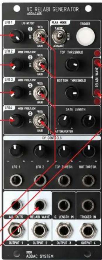
Secondary LFOs Functions:
All secondary function can be changed by fastly toggling the switch from the the Up position (FREQ.) to the Middle position (OFF) and back to the Up position, to monitor this change the Trigger Button Led will blink once for the Left Function and twice for the right function (INT/EXT & FREE/LOCK1).
LF01 INT/EXT:
- Left function INT sets the LFO as an INTernal LFO, in this case the CV input will change the Frequency or Gain depending on the switch position.
- Right function EXT sets the CV input to be a direct CV input into the LFOs mix, this CV input will then be mixed with the remaining active LFOs to create the "Relabi Wave". In this setting the Gain switch position has no effect as the CV can already be attenuated by the dedicated attenuverter.
LF02, 3 & 4 FREE/LOCK1:
- Left function FREE sets each LFO to be independent from LFO1.
- Right function LOCK1 sets each LFO to be locked to the LF01 frequency, in this case the Frequency setting will operate as a divider/multiplier of LF01 (1/16, 1/8, 1/4, 1/3, 1/2, 1/1.5, 1/1.33333, 1*1.25, 1*1.333333f, 1*1.5, 1*1.75, 1*2, 1*3, 1*4, 1*5, 1*6, 1*7, 1*8).

DESCRIPTION
The Relabi Wave will then be compared to 2 Threshold points defined by the Top and Bottom Threshold controls. Every time the Relabi Wave crosses one of these thresholds each specific Output will go on accordingly:
Output 1: Relabi Wave goes higher than Top Threshold
Output 2: Relabi Wave goes lower than Top Threshold
Output 3: Relabi Wave goes higher than Bottom Threshold
Output 4: Relabi Wave goes lower than Bottom Threshold
These 4 Outputs are variable length Gate outputs defined by the Gate Length controls.
Top Threshold Led Goes On When the Relabi Wave is higher than the threshold setting.
Bottom Threshold Led Goes On When the Relabi Wave is lower than the threshold setting.
The 4 Outputs are also converted to a Trigger and mixed down into the ALL OUTS jack.

MEMORY
All LFO settings are saved in memory and recovered upon start-up.
PLAY MODES
PAUSE: in PAUSE mode the Trigger Button and Trigger Input will pause the generator and the Button Led will go ON.
RESET: at every TRIGGER Button Push or Trigger Input all LFOs will Reset and synchronize, this allows to generate repeatable patterns.
ADVANCE: at every TRIGGER Button Push or Trigger Input the generator will advance to the next cross point and pause, using the ALL OUTS this allows for a very peculiar kind of trigger delay.

This module will also be available as a full DIY kit.
MSRP: 250€
Shipping: Late November
Tech Specs:
10HP
4cm deep
100mA +12V
40mA -12V
ADDAC405
VC RELABI GENERATOR LOGIC TRUTH TABLE

line
| Signal | Value | | ------------ | ----- | | TOP LED | +5v | | OUT 1 | +5v | | OUT 2 | +5v | | OUT 3 | +5v | | OUT 4 | +5v | | BOTTOM LED | +5v | | ALL OUTS | +5v |
line
| Gate Length | Value | |-------------|-------| | OUT 1 | Red | | OUT 2 | Yellow| | OUT 3 | Yellow| | OUT 4 | Green | | BOTTOM LED | Blue | | ALL OUTS | Orange| NETTLEMENTS > BOTTOM THRESHOLD GATE LENGTHS GATEL LENGTHS FIXED 1M: TRIGGER SIZECONTROLS DESCRIPTION

ADDAC405
VC RELABI GENERATOR SIGNAL FLOW DIAGRAM

flowchart
graph TD
    A["TYPE LENGTH"] --> B["CY INPUT ATTENUER"]
    C["TOP COMPARATOR THRESHOLD"] --> D["CY INPUT ATTENUER"]
    E["TRQUENCU / OT / SAIN"] --> F["LFD 1 CAN ACCEPT AN EXTERNAL SOURCE INSTEAD OF INTERNAL LFD"]
    G["LFD 1 CONTROL"] --> F
    H["CY INPUT ATTENUER"] --> I["LFD 2 CAN ALSO BE A DIVISION OR MULTIFICATION OF LFD"]
    J["FREQUENCY / OFF / SAIN"] --> K["LFD 3 CAN ALSO BE A DIVISION OR MULTIFICATION OF LFD"]
    L["LFD 2 CONTROL"] --> K
    M["CY INPUT ATTENUER"] --> N["LFD 4 CAN ALSO BE A DIVISION OR MULTIFICATION OF LFD"]
    O["TRQUENCU / OT / SAIN"] --> P["LFD 3 CONTROL"]
    Q["LFD 3 CONTROL"] --> P
    R["FREQUENCY / OT / SAIN"] --> S["LFD 4 CONTROL"]
    T["FLAV MODE: PAUSE/RESET/ADVANCE"] --> U["TRIGGER/GATE: PAUSE/RESET/ADVANCE"]
    V["TRIGGER/GATE INPUT: PAUSE/RESET/ADVANCE"] --> W["TRIGGER/GATE INPUT: PAUSE/RESET/ADVANCE"]
    X["TOP COMPARATOR MONITOR LED ON WHILE ABOVE THRESHOLD"] --> Y["TOP COMPARATOR MONITOR LED ON WHILE ABOVE THRESHOLD"]
    Z["OUTPUT 1 TRIGGER/GATE CROSSERS THRESHOLD GOING UP"] --> AA["TOP COMPARATOR MONITOR LED ON WHILE ABOVE THRESHOLD"]
    AB["OUTPUT 2 TRIGGER/SATE CROSSERS THRESHOLD GOING DOWN"] --> AC["TOP COMPARATOR MONITOR LED ON WHILE ABOVE THRESHOLD"]
    AD["ALL OUTS CALL 4 OUTPUTS CONVERTED TO TRICERSMIXED AND MIXED"] --> AE["TOP COMPARATOR MONITOR LED ON WHILE ABOVE THRESHOLD"]
    AF["OUTPUT 3 TRIGGER/SATE CROSSERS THRESHOLD GOING DOWN"] --> AG["TOP COMPARATOR MONITOR LED ON WHILE BELOW THRESHOLD"]
    AH["OUTPUT 4 TRIGGER/SATE CROSSERS THRESHOLD GOING UP"] --> AI["TOP COMPARATOR MONITOR LED ON WHILE BELOW THRESHOLD"]
    AJ["RELABI WAVE CY OUTPUT"] --> AK["TOP COMPARATOR MONITOR LED ON WHILE BELOW THRESHOLD"]
    AL["DOTCOM COMPARATOR"] --> AM["TOP COMPARATOR MONITOR LED ON WHILE BELOW THRESHOLD"]
    AN["DOTCOM COMPARATOR THRESHOLD"] --> AO["TOP COMPARATOR MONITOR LED ON WHILE BELOW THRESHOLD"]
    AP["CY INPUT ATTENUER"] --> AQ["TOP COMPARATOR MONITOR LED ON WHILE ABOVE THRESHOLD"]
    AR["CY INPUT ATTENUER"] --> AS["TOP COMPARATOR MONITOR LED ON WHILE ABOVE THRESHOLD"]
For feedback, comments or problems please contact us at: addac@addacsystem.com
Brand : ADDAC System
Model : ADDAC405
Category : Module audio modulaire