
DS8116HCIST - Voice recorder Syscom - Free user manual and instructions
Find the device manual for free DS8116HCIST Syscom in PDF.


| Product Type | Voice Recorder |
| Brand | Syscom |
| Model | DS8116HCIST |
| Recording Format | MP3 / WMA |
| Recording Quality | Multiple bitrates (32-192 kbps) |
| Internal Memory | 8 GB |
| Expandable Memory | microSD up to 32 GB |
| Maximum Recording Time | Up to 576 hours (at 32 kbps) |
| Battery Type | Lithium-ion rechargeable |
| Battery Capacity | 600 mAh |
| Playback | Built-in speaker and headphone jack |
| Display | LCD screen with backlight |
| Microphone | Built-in stereo microphone |
| Dimensions | 110 x 40 x 15 mm |
| Weight | 75 g (with battery) |
| Connectivity | USB 2.0, micro-USB port |
| Power Source | USB charging or AC adapter (5V, 1A) |
| Supported Languages | English, French, Spanish, etc. |
| Key Features | Voice-activated recording, A-B repeat, variable playback speed |
| Included Accessories | USB cable, earphones, carrying case, wrist strap |
| Cleaning | Wipe with a soft, dry cloth; avoid liquids |
| Storage | Store in a cool, dry place away from direct sunlight |
Frequently Asked Questions - DS8116HCIST Syscom
User questions about DS8116HCIST Syscom
0 question about this device. Answer the ones you know or ask your own.
Ask a new question about this device
Download the instructions for your Voice recorder in PDF format for free! Find your manual DS8116HCIST - Syscom and take your electronic device back in hand. On this page are published all the documents necessary for the use of your device. DS8116HCIST by Syscom.
USER MANUAL DS8116HCIST Syscom
Hikvision® Network Digital Video Recorder User's Manual
This manual, as well as the software described in it, is furnished under license and may be used or copied only in accordance with the terms of such license. The content of this manual is furnished for informational use only, is subject to change without notice, and should not be construed as a commitment by Hikvision Digital Technology Co., Ltd. (Hikvision). Hikvision assumes no responsibility or liability for any errors or inaccuracies that may appear in the book.
Except as permitted by such license, no part of this publication may be reproduced, stored in a retrieval system, or transmitted, in any form or by any means, electronic, mechanical, recording, or otherwise, without the prior written permission of Hikvision.
HIKVISION MAKES NO WARRANTIES, EXPRESS OR IMPLIED, INCLUDING WITHOUT LIMITATION THE IMPLIED WARRANTIES OF MERCHANTABILITY AND FITNESS FOR A PARTICULAR PURPOSE, REGARDING THE HIKVISION SOFTWARE. HIKVISION DOES NOT WARRANT, GUARANTEE, OR MAKE ANY REPRESENTATIONS REGARDING THE USE OR THE RESULTS OF THE USE OF THE HIKVISION SOFTWARE IN TERMS OF ITS CORRECTNESS, ACCURACY, RELIABILITY, CURRENTNESS, OR OTHERWISE. THE ENTIRE RISK AS TO THE RESULTS AND PERFORMANCE OF THE HIKVISION SOFTWARE IS ASSUMED BY YOU. THE EXCLUSION OF IMPLIED WARRANTIES IS NOT PERMITTED BY SOME STATES. THE ABOVE EXCLUSION MAY NOT APPLY TO YOU.
IN NO EVENT WILL HIKVISION, ITS DIRECTORS, OFFICERS, EMPLOYEES, OR AGENTS BE LIABLE TO YOU FOR ANY CONSEQUENTIAL, INCIDENTAL, OR INDIRECT DAMAGES (INCLUDING DAMAGES FOR LOSS OF BUSINESS PROFITS, BUSINESS INTERRUPTION, LOSS OF BUSINESS INFORMATION, AND THE LIKE) ARISING OUT OF THE USE OR INABILITY TO USE THE HIKVISION SOFTWARE EVEN IF HIKVISION HAS BEEN ADVISED OF THE POSSIBILITY OF SUCH DAMAGES. BECAUSE SOME STATES DO NOT ALLOW THE EXCLUSION OR LIMITATION OF LIABILITY FOR CONSEQUENTIAL OR INCIDENTAL DAMAGES, THE ABOVE LIMITATIONS MAY NOT APPLY TO YOU.
Thank you for purchasing our product. If there is any question or request, please do not hesitate to contact dealer.
This manual is applicable to DS-8104/8108/8116HCI-ST (V1.1.0), DS-8104/8108AH (L) I-ST (V1.1.0) and
DS-8104/8108AHF (L) I-ST (V3.2.0) series DVR.
This manual may contain several technically incorrect places or printing errors, and the content is subject to change without notice. The updates will be added into the new version of this manual. We will readily improve or update the products or procedures described in the manual.
Preventive and Cautionary Tips
Before connecting and operating your DVR, please be advised of the following tips:
- Ensure unit is installed in a well-ventilated, dust-free environment.
- Unit is designed for indoor use only.
- Keep all liquids away from the DVR.
- Ensure environmental conditions meet factory specifications.
- Ensure unit is properly secured to a rack or shelf. Major shocks or jolts to the unit as a result of dropping it may cause damage to the sensitive electronics within the unit.
- Use the DVR in conjunction with an UPS if possible.
• Power down the unit before connecting and disconnecting accessories and peripherals. - A factory recommended HDD should be used for this device.
- Improper use or replacement of the battery may result in hazard of explosion. Replace with the same or equivalent type only. Dispose of used batteries according to the instructions provided by the battery manufacturer.
TABLE OF CONTENTS
CHAPTER 1....7
Introduction....7
Overview....8
Product Features....9
Product Application Diagram....11
Operating Your DVR....12
Using the Front Panel Controls 12
Using the IR Remote Control....15
Using the USB Mouse.... 17
Using the Soft Keyboard....17
Rear Panel....18
CHAPTER 2....21
Getting Started....21
Starting and Shutting Down Your DVR....22
Rebooting and Locking Your DVR 22
Using the Setup Wizard 22
Setting Date & Time 26
CHAPTER3....28
Live Preview 28
Live Preview On-screen Display....29
Live Preview Icons....29
Live Preview Operation....29
Mouse Operation in Live Preview 30
Digital Zoom 30
Configuring Live Preview Display 31
Setting Camera Order....32
CHAPTER 4....33
Record Settings 33
Configuring Record Settings.... 34
Before Record Settings 34
Initializing Record Settings.... 34
Scheduling a Recording 36
Starting a Manual Recording....36
Protecting Recorded Files 37
Locking/Unlocking Recorded Files.... 37
Setting HDD to Read-Only 38
Configuring Advanced HDD Settings.... 39
Setting up HDD Redundancy 39
CHAPTER 5....42
Playback 42
Video Playback....43
Playback Interface....43
Playback by Video Search 43
Playback by Event Search 44
Playback by Card Number 46
Playback by Preview Mode....47
Playback by System Log 47
Playback Frame-by-Frame 48
Digital Zoom 48
CHAPTER 6....50
Backup 50
Backing up Recorded Files 51
Exporting Files....51
Exporting Video Clips....54
Exporting Files via e-SATA 55
Managing Backup Devices 56
CHAPTER 7....57
Alarm Settings....57
Configuring Alarms 58
Motion Detection Alarm 58
Sensor Alarm Settings....61
Manual Alarm Triggering 63
Video Loss Detection....64
Video Tampering Detection 66
Exception Settings 68
Understanding Exception Trigger Options....68
CHAPTER 8....70
Network Settings 70
Configuring Network Settings 71
General Settings....71
PPPOE Settings....72
DDNS Settings....73
NTP Server Settings....74
Remote Alarm Host Settings....75
Multicast Settings....75
Server and HTTP Ports Settings....76
E-mail Settings....77
CHAPTER 9....78
PTZ Control 78
PTZ Menu 79
PTZ Settings 79
Setting PTZ Presets, Patrols & Patterns 80
Understanding PTZ Control 80
Setting Presets 81
Setting Patrols 81
Setting Patterns 83
CHAPTER 10....84
Camera Management 84
OSD Settings....85
Display Settings 85
Privacy Mask Settings....86
CHAPTER 11....88
HDD Management 88
Managing HDDs 89
Initializing HDDs 89
Setting Network HDD 89
Setting HDD Groups 91
Setting HDD Status 92
Setting HDD to Read-Only 92
Setting HDD to Redundancy 93
Checking HDD Status 93
Configuring HDD Alarms....95
CHAPTER 12....97
ATM Settings 97
Network Interception 98
Serial Interception....102
Network Protocol....104
Network Protocol....105
CHAPTER 13....106
DVR Management 106
Configuring System Settings.... 107
Configuring General Settings.... 107
Configuring Advanced Settings 107
RS-232 Port Settings....108
Managing User Accounts....109
Adding a New User.... 109
Deleting a User 112
Modifying a User 112
Managing System....113
Importing & Exporting Configuration.... 113
Updating System Firmware.... 113
Restoring Default Settings 115
Viewing System Information 115
Viewing System Log.... 116
CHAPTER 14....118
Appendix....118
Glossary 119
FAQ 120
CHAPTER1
Introduction
Overview
Developed on the basis of the latest technology, DS-8100-ST Series Digital Video Recorder combines the latest in advanced H.264 video encoding and decoding technologies delivering high performance rock-solid reliability and longer recording times.
DS-8100-ST Digital Video Recorder can be used as a standalone video surveillance product, as well as to build up a powerful surveillance network making it is perfect for home or small business applications.

Figure 1. DS-8100HCI-ST Series DVR

Figure 2. DS-8100AH (F) LI-ST Series DVR
Product Features
Compression
- PAL/NTSC adaptive video inputs.
H.264 video compression with high reliability and superior definition.
- Up to 4CIF resolution.
● Independent video encoding parameters, including frame rate, resolution, bit rate, video quality, etc.
- Scheduled and event recording parameters configurable per individual camera.
- Support dual stream.
- Encoding for both audio/video composite stream and video stream; audio and video synchronization during composite stream encoding.
Local Monitoring
● Up to 1024×768 resolution for VGA output display.
● VGA and main CVBS outputs available; DS-8100HCI-ST also provides spot video output.
● 1/4/9/16-camera video live view, with the camera order adjustable.
- Group switch, manual switch and automatic cycle modes selectable for video live view, with the auto cycle period configurable.
● Digital zoom in live view mode.
● Shield of assigned channel for live view.
● Motion detection, video loss detection, video tampering detection.
● Privacy mask capability.
● Multiple PTZ protocols supported, and settings and callup of presets, patrols and patterns.
● Video image zoom-in by clicking the mouse and tracing by dragging mouse in PTZ control mode.
Hard Disk Management
- Up to 8 SATA hard disks, 8 network disks (8 NAS disks, or 7 NAS disks+1 iSCSI disk) and 1 eSATA disk can be connected to DS-8108HCI-ST and DS-8116HCI-ST model, each disk with a maximum of 2TB storage capacity; eSATA disk can be used for recording or backup.
- Up to 4 SATA hard disks, 8 network disks can be connected to DS-8104HCI-ST and DS-8100AH (F) (L) I-ST model, each disk with a maximum of 2TB storage capacity.
S. M. A. R. T technology.
- HDD standby function.
● Hard disk group management.
- HDD property can be set to redundant, read-only or read/write.
- HDD file system is compatible with Windows. Use pre-allocating hard disk management technology, and no disk fragments.
Recording
● Cycle and non-cycle recording mode.
- Scheduled and event video encoding parameters.
- Multiple recording types, including manual, continuous, alarm, motion, motion | alarm and motion & alarm recording; command triggered recording is supported by DS-8100AH (F) (L) I-ST.
● 8 recording time periods configurable with separate recording types.
● Pre-record and post-record for motion detection, alarm, motion | alarm and motion & alarm recording; pre-record for scheduled and manual recording.
- Lock and unlock of video files.
- Local redundant recording.
- Video data search and playback by channel number, recording type, start/end time, etc.; DS-8100AH (F) (L)I-ST model supports video search and playback by card number.
● Digital zoom function in playback mode.
● Pause, play fast, play slow, skip forward, and skip backward when playback, locating in progress bar by dragging the mouse.
● Up to 4/8/16-channel synchronous playback.
Backup
● Record files backed up via USB, SATA or eSATA (for DS-8100HCI-ST) device.
● Support built-in SATA CD/DVD-R/W backup.
● Bunch backup by file or by time.
● Video clips backup when playback.
● Management and maintenance for backup devices.
Alarm & Exception
- Configurable arming time for alarm in/out.
● Various alarm types supported: alarms for video loss, motion detection, video tempering, video in/out format unmatched, illegal access, network disconnection, IP conflict, hard disk error, hard disk full and abnormal recording.
● Various alarm response actions supported: pop up alarm pictures, trigger alarm out, notify surveillance center, audible warning, E-mail notification, etc.; motion detection and relay alarm can trigger camera recording.
● Auto recovery from exceptions.
Others
● Control of DVR via front panel keys, mouse, and IR remote control.
● Three-level user administration, each user with individual operating permission for DVR and camera.
● Powerful record and search for log of operation, alarm and exceptions.
- Import/export of device configuration files.
● Support record files search and playback by event.
● Watermark technology.
Network
- 10M/100M adaptive network interface for DS-8100HCI-ST and DS-8100AH (L) I-ST model, and 10M/100M/1000 M adaptive network interface for DS-8100AHF (L) I-ST model.
● TCP/IP protocol suites, PPPoE, DHCP, DNS, DDNS, NTP, SADP, SMTP protocols, etc.
● Unicast and multicast supported; TCP and UDP protocols applicable in unicast transmission. - Remote search, playback and download, lock/unlock of video files.
● Support breakpoint resume. - Remote access and configuration of parameters; remote import/export of device configuration parameters.
● Remote access of device running status, system log and alarm status. - Remote control of DVR via button operation.
- Remote lock/unlock of panel buttons and mouse.
● Remote formatting of hard disk, upgrade, reboot/shutdown and other system maintenance operations.
● RS-232 and RS-485 transparent channel transmission.
● Event alarm and exceptions upload to remote management host. - Remote manual recording.
- Remote video image capture in JPEG format.
- Remote PTZ control.
● Voice talk and broadcast.
● Built-in WEB Server.
Development
● Provision of SDK in Windows and Linux operating systems.
● Application software source code of Demo.
● Support and training service for application system development.
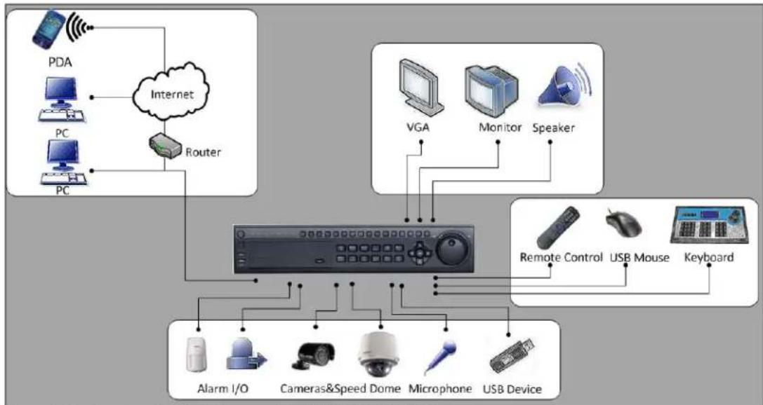
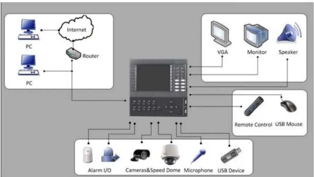
Product Application Diagram
flowchart
graph TD
    A["PDA"] --> B["Internet"]
    C["PC"] --> B
    D["PC"] --> B
    B --> E["Router"]
    F["VGA"] --> G["Monitor"]
    G --> H["Speaker"]
    I["Remote Control"] --> J["USB Mouse"]
    K["Keyboard"] --> L["USB Device"]
    M["Alarm I/O"] --> N["Cameras&Speed Dome"]
    N --> O["Microphone"]
    O --> P["USB Device"]
Figure 3. Product Application Diagram (DS-8100HCI-ST DVR)
flowchart
graph TD
    subgraph PC
        A["PC"] --> B["Internet"]
        C["PC"] --> B
        B --> D["Router"]
    end
    subgraph Internet
        B --> D
    end
    subgraph Router
        D --> E["Computer"]
    end
    subgraph VGA
        E --> F["Monitor"]
        E --> G["Speaker"]
    end
    subgraph Remote Control
        H["USB Mouse"] --> I["Remote Control"]
        I --> J["USB Device"]
    end
    subgraph USB Mouse
        K["Alarm I/O"] --> L["Cameras&Speed Dome"]
        M["Microphone"] --> L
        N["USB Device"] --> L
    end
Figure 4. Product Application Diagram(DS-8100AH (F) (L) I-ST DVR)
Operating Your DVR
There are numerous ways to navigate and operate your DVR. You may use the Front Panel Controls, the included IR (Infrared) Remote, a Mouse and the Soft Keyboard.
Using the Front Panel Controls
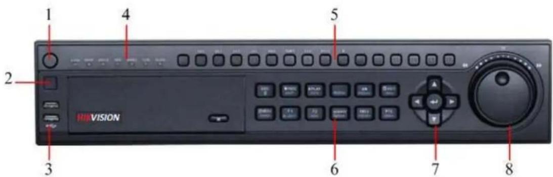
Figure 5. DS-8100HCI-ST DVR Front Panel
The controls on the front panel include:
- Power Button: Powers DVR on/off.
- IR Receiver: Receiver for IR remote.
- USB Ports: Universal Serial Bus (USB) ports for additional devices such as USB mouse and USB Hard Disk Drive (HDD).
-
Status Indicators: Status indicators for different features of the DVR.
-
Alarm: Alarm indicator turns red when a sensor alarm is detected.
- Ready: Ready indicator turns blue when DVR is functioning properly.
- Status: Status indicator turns blue when DVR is controlled by an IR remote. Indicator turns red when controlled by a keyboard and purple when IR remote and keyboard is used at the same time.
- HDD: HDD indicator blinks red when data is being read from or written to HDD.
- Modem: Reserved.
- TX/RX: TX/RX indicator blinks blue when network connection is functioning properly.
-
Guard: Guard indicator turns blue when the device is armed, off when the device is unarmed. The arm/disarm state can be initiated by pressing and holding on the ESC button for more than 3 seconds in Preview mode.
-
Alphanumeric Buttons: Alphanumeric buttons used in various menus of the DVR. Some uses include:
-
Switching to the corresponding channel in Preview or PTZ Control mode.
- Inputting numbers and characters in Edit mode.
-
Switching between different channels in Playback mode.
-
Control Buttons:
-
ESC Button: The ESC button is used to escape to the previous menu and to arm/disarm the DVR in Preview mode.
- REC/SHOT Button: The REC/SHOT button is used to enter the Manual Record interface. If used when controlling a PTZ, pressing the REC/SHOT button and then a Numeric button will call a PTZ preset.
- PLAY/AUTO Button: The PLAY/AUTO button is used to enter the Playback menu. It is also used to turn audio on/off in the Playback menu and auto scan in the PTZ Control menu.
-
ZOOM+ Button: The ZOOM+ button is used to zoom the PTZ camera in when in the PTZ Control menu.
-
A/FOCUS+ Button: The A/FOCUS+ button is used to adjust focus in the PTZ Control menu. It is also used to switch between input methods (upper and lowercase alphabet, symbols and numeric input). It can also be used to clear entire masked areas, such as in the Motion Detection and Privacy Mask menus.
- EDIT/IRIS+ Button: The EDIT/IRIS+ button is used to edit text fields. When editing text fields, it will also function as a Backspace button to delete the character in front of the cursor. On checkbox fields, pressing the EDIT/IRIS+ button will tick the checkbox. In PTZ Control mode, the EDIT/IRIS+ button opens up the iris of the camera. In Playback mode, it can be used to generate video clips for backup.
- MENU/WIPER Button: Pressing the MENU/WIPER button will return the user to the Main menu (after successful login). Pressing and holding the button for 5 seconds will turn off audible key beep. The MENU/WIPER button will also bring up Sensitivity Interface settings. In PTZ Control mode, the MENU/WIPER button will start wiper (if applicable).
- F1/LIGHT Button: The F1/LIGHT button when used in a list field will select all items on the list. In PTZ Control mode, it will turn on/off PTZ light.
- F2/AUX Button: The F2/AUX button is used to cycle through tab pages. It will also bring up the Channel & OSD Position settings.
- MAIN/SPOT/ZOOM- Button: The MAIN/SPOT/ZOOM- button is used to switch to the control of spot output. In PTZ Control mode, it can be used to zoom the camera out.
- PREV/FOCUS- Button: The PREV/FOCUS- button is used to switch between single screen and multi-screen mode. In PTZ Control mode, it is used to adjust the focus in conjunction with the A/FOCUS+ button. It can also be used to select entire masked areas, such as in Motion Detection and Privacy Mask menus.
- PTZ/IRIS- Button: The PTZ/IRIS- button is used to enter the PTZ Control mode. When in the PTZ Control mode, it is used to close the iris of the PTZ camera.
7. DIRECTION/ENTER Buttons:
- DIRECTION Buttons: The DIRECTION buttons are used to navigate between different fields and items in menus. In Playback mode, the Up and Down button is used to speed up and slow down recorded video. The Left and Right button will select the next and previous day of recordings. In Preview mode, these buttons can be used to cycle through channels.
-
ENTER Button: The ENTER button is used to confirm selection in any of the menu modes. It can also be used to tick checkbox fields. In Playback mode, it can be used to play or pause the video. In Single Play mode, pressing the ENTER button will advance the video by a single frame.
-
JOG SHUTTLE Control: The JOG SHUTTLE control can be used to move the active selection in a menu. The inner ring will move the selection up and down; the outer ring will move it left and right. In the Playback mode, the inner ring is used to jump 30s forward/backward in video files. The outer ring can be used to speed up/slow down the video. In Preview mode, it can be used to cycle through different channels.
Note: If GUARD indicator is blue (default), all alarm event and exception settings are valid. Otherwise, alarm event and exception settings will be invalid, but normal recording will still be available.
Note: It is important to note that you must click the EDIT button on either the remote or front panel on a text field before you're able to edit its content. After you're done entering text, you must hit the ENTER button to be able to move on to the next field.

Figure 6. DS-8100AII(F)LI-ST DVR Front Panel
The controls on the front panel include:
- LCD: Display local menu and preview.
Note: DS-8100AH (F) I-ST model is designed with no LCD.
-
Status Indicators: Status indicators for different features of the DVR.
-
Num Lock: Press SHIFT button, the Num Lock indicator will turn on to blue, the control buttons will be used to input letters and numbers. Press SHIFT button again, the NumLock indicator will turn off, and the control buttons will resume.
- Ready: Ready indicator turns green when DVR is functioning properly.
- Status: Status indicator turns green when DVR is controlled by an IR remote.
- Alarm: Alarm indicator turns red when a sensor alarm is detected.
- Modem: Reserved.
- HDD: HDD indicator blinks red when data is being read from or written to HDD.
- Link: Link indicator is blue when network connection is functioning properly.
- Tx/Rx: TX/RX indicator blinks blue when network connection is functioning properly.
- Ch1-Ch8: The channel status indicator lights in green for recording of its corresponding channel, red for data transmission, and orange for both recording and data transmission.
Note: Only Ch1-Ch4 channel status indicators are valid for DS-8104AH (F) (L)I-ST model.
-
Control Buttons:
-
1/MENU Button: The 1/MENU button works as numeric [1]. Pressing this button will return the user to the Main menu (after successful login). The 1/MENU button will also bring up Sensitivity Interface settings.
- 2ABC/VOIP: The 2ABC button works as numeric [2] and letter [ABC]. When it is used in a list field will select all items on the list.
- 3DEF/INFO: The 3DEF button works as numeric [3] and letter [DEF]. It is also used to cycle through tab pages.
- 4GHI/ESC: The 4GHI/ESC button works as numeric [4] and letter [GHI], it is also used to escape to the previous menu.
- 5JKL/EDIT: The 5JKL/EDIT button works as numeric [5] and letter [JKL]. The 5JKL/EDIT button is used to edit text fields. When editing text fields, it will also function as a Backspace button to delete the character in front of the cursor. On checkbox fields, pressing the EDIT/IRIS+ button will tick the checkbox. In Playback mode, it can be used to generate video clips for backup.
- 6MNO/PLAY: The 6MNO/PLAY button works as numeric [6] and letter [MNO]. It is used to enter the Playback menu. It is also used to turn audio on/off in the Playback menu.
- 7PQRS/REC: The 7PQRS/REC button works as numeric [7] and letter [PQRS]. It is also used to enter the
Manual Record interface.
- 8TUV/PTZ: The 8TUV/PTZ button works as numeric [8] and letter [TUV]. It is also used to enter the PTZ Control mode.
- 9WXYZ/PREV: The 9WXYZ/PREVIEW button works as numeric [9] and letter [WXYZ]. It is also used to switch between single screen and multi-screen mode.
- 0/A: The 0/A button works as numeric [0]. It is also used to switch between input methods (upper and lowercase alphabet, symbols and numeric input). It can also be used to clear entire masked areas, such as in the Motion Detection and Privacy Mask menus.
- SHIFT: The SHIFT button is used for switch button action between numeric button and control button.
4. DIRECTION/ENTER Buttons:
- DIRECTION Buttons: The DIRECTION buttons are used to navigate between different fields and items in menus. In Playback mode, the Up and Down button is used to speed up and slow down recorded video. The Left and Right button will jump 30s backward and forward in a video. In Preview mode, these buttons can be used to cycle through channels.
-
ENTER Button: The ENTER button is used to confirm selection in any of the menu modes. It can also be used to tick checkbox fields. In Playback mode, it can be used to play or pause the video. In Single Play mode, pressing the ENTER button will advance the video by a single frame.
-
POWER Button: The POWER button is used for power on or power off the DVR.
-
USB Ports: Universal Serial Bus (USB) ports for additional devices such as USB mouse and USB Hard Disk Drive (HDD).
Note: It is important to note that you must click the EDIT button on either the remote or front panel on a text field before you're able to edit its content. After you're done entering text, you must hit the ENTER button to be able to move on to the next field.
Using the IR Remote Control
Your DVR may also be controlled with the IR remote control, shown in Figure 7. Batteries (2×AAA) must be installed before operation.

Figure 7. IR Remote Control
The keys on the remote control closely resemble the ones found on the front panel. Referring to Figure 5, they include:
- POWER Button: Same as POWER button on front panel
- DEV Button: Enables/Disables Remote Control.
- Alphanumeric Buttons: Same as Alphanumeric buttons on front panel.
- EDIT Button: Same as EDIT/IRIS+ button on front panel.
- A Button: Same as A/FOCUS+ button on front panel.
- REC Button: Same as REC/SHOT button on front panel.
- PLAY Button: Same as PLAY/AUTO button on front panel.
- INFO Button: Same as ZOOM+ button on front panel.
- VOIP Button: Same as MAIN/SPOT/ZOOM- button on front panel.
- MENU Button: Same as MENU/WIPER button on front panel.
- PREV Button: Same as PREV/FOCUS- button on front panel.
- DIRECTION/ENTER Buttons: Same as DIRECTION/ENTER buttons on front panel.
- PTZ Button: Same as PTZ/IRIS- button on front panel.
- ESC Button: Same as ESC button on front panel.
- RESERVED: Reserved.
- F1 Button: Same as F1/LIGHT button on front panel.
- PTZ CONTROL Buttons: Buttons to adjust the iris, focus and zoom of a PTZ camera.
- F2 Button: It is also used to cycle through tab pages.
Aim the remote control at the IR receiver located at the front of the unit to test operation. If there is no response:
- Using the front control panel or the mouse, go into Menu > Settings > General > More Settings.
- Check and remember DVR ID#. The default ID# is 255. This ID# is valid for all IR controls.
- Press the DEV button on the remote.
- Enter the DVR ID# from step 2.
- Press the ENTER button on the remote.
If the Status indicator on the front panel turns blue, the remote control is operating properly. If the Status indicator does not turn blue and there is still no response from the remote, please check the following:
- Batteries are installed correctly and the polarities of the batteries are not reversed.
- Batteries are fresh and not out of charge.
- IR receiver is not obstructed.
Using the USB Mouse
A regular 3-button (Left/Right/Scroll-wheel) USB mouse can also be used with this DVR. To use a USB mouse:
-
Plug USB mouse into one of the USB ports on the front panel of the DVR.
-
The mouse should automatically be detected. If in a rare case that the mouse is not detected, please refer to the recommended device list from your provider.
The buttons on the mouse corresponds to:
1. Left Button:
- Single-Click: Select a component of a menu, such as a button or an input field. This is similar to pressing the ENTER button on the remote/front panel controls.
- Double-Click: Switch between single screen and multi-screen mode in Preview/Playback mode.
- Click and Drag: Clicking and dragging the Left mouse button can be used to control the pan/tilt of a PTZ camera as well as to vary the position of digital zoom area and camera OSD. It can also be used to setup the alarm areas.
2. Right Button:
- Single-Click: Shows pop-up menu.
3. Scroll-Wheel:
- Scroll Up: In Preview mode, scrolling up will switch to the previous screen. In Menu mode, it will move the selection to the previous item.
- Scroll Down: In Preview mode, scrolling down will switch to the next screen. In Menu mode, it will move the selection to the next item.
Using the Soft Keyboard
When a mouse is used to perform task on the DVR, clicking on a text input field will bring up the Soft Keypad, shown in Figure 8.

Figure 8. Soft Keypad
The buttons on the soft keyboard represents:
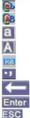
Figure 9. Soft Keyboard Buttons
Lowercase: Designates lowercase input is being used.
Uppercase: Designates uppercase input is being used.
Switch to Uppercase: Switch to uppercase input.
Switch to Lowercase: Switch to lowercase input.
Number: Designates number input is being used.
Symbols: Switch to symbols input.
Backspace: Delete the character in front of the cursor.
Enter: Confirm selection.
ESC: Exit out of Soft Keyboard.
Rear Panel
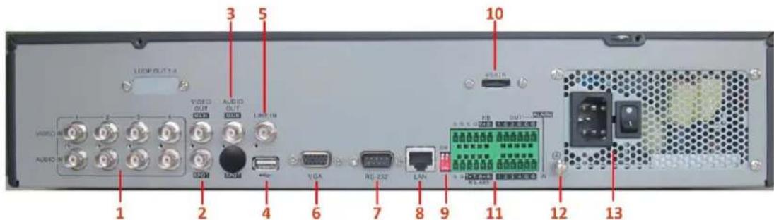
Figure 10. DS-8104HCI-ST Rear Panel
| No. | Item Description | |
| 1 | VIDEO IN BNC connectors for analog video input. | |
| AUDIO IN | BNC connectors for analog audio input. | |
| 2 | MAIN VIDEO OUT | BNC connectors for main video out. If VGA is connected when the device is started up, this interface will be used as the Aux video output with live view and pop-up alarm picture operations. If VGA is not connected, this interface will be used as the main video output with local video display and menu operations. |
| SPOT VIDEO OUT | BNC connector for spot video out. | |
| 3 | AUDIO OUT BNC connector for main audio output. | |
| 4 | USB Interface Connector for USB devices. | |
| 5 | LINE IN BNC connector for audio input. | |
| 6 | VGA | VGA output. Display local video output and menu. If VGA is connected when the device is started up, the MAIN VIDEO OUT interface will be used as the Aux video output with live view and pop-up alarm picture operations. If VGA is not connected, the MAIN VIDEO OUT interface will be used as the main video output with local video display and menu operations. |
| 7 | RS-232 | DB9 connector for connection to RS-232 devices. |
| 8 | LAN Interface Connector for LAN (Local Area Network). | |
| 9 | Termination Switch | RS-485 termination switch. ON: not terminated; OFF: connect with 120Ω termination. |
| 10 | cSATA Interface | cSATA interface for storage and backup |
| 11 | RS-485 Interface | Connectors for RS-485 devices. T+, T- pin connects to PTZ. |
| Controller port | D+, D- pin connects to Ta, Tb pin of controller. For cascading devices, the first DVR's D+, D- pin should be connected with the D+, D- pin of the next DVR. | |
| ALARM IN | Connector for alarm input. | |
| ALARM OUT | Connector for alarm output. | |
| 12 | GROUND | Ground(needs to be connected when DVR starts up) |
| 13 | POWER | 100~240VAC power supply |

Figure 11. DS-8108/8116HCI-ST Rear Panel
Note: DS-8108HCI-ST provides 8 video inputs and 8 audio inputs on rear panel.
| No. | Item | Description |
| 1 | VIDEO IN BNC connectors for analog video input. | |
| AUDIO IN BNC connectors for analog audio input. | ||
| 2 | VIDEO SPOT OUT BNC connector for monitor. Single-window view. | |
| 3 | VIDEO OUT | BNC connector for video output. If VGA is connected when the device is started up, this interface will be used as the Aux video output with live view and pop-up alarm picture operations. If VGA is not connected, this interface will be used as the main video output with local video display and menu operations. |
| AUDIO OUT BNC connector for audio output. This connector is synchronized with VIDEO OUT. | ||
| 4 | LINE IN BNC connector for audio input. | |
| 5 | VGA | VGA output. Display local video output and menu. If VGA is connected when the device is started up, the VIDEO OUT interface will be used as the Aux video output with live view and pop-up alarm picture operations. If VGA is not connected, t VIDEO OUT interface will be used as the main video output with local video display and menu operations. |
| 6 | RS-232 | DB9 connector for connection to RS-232 devices. |
| 7 | LAN Interface Connector for LAN (Local Area Network). | |
| 8 | USB Interface | Connector for USB devices. |
| 9 | eSATA Interface | eSATA interface for storage and backup |
| 10 | Termination Switch | RS-485 termination switch. ON: not terminated; OFF: connect with 120Ω termination. |
| 11 | RS-485 Interface Connectors for RS-485 devices. T+, T- pin connects to PTZ. | |
| Controller port | D+, D- pin connects to Ta, Tb pin of controller. For cascading devices, the first DVR's D+, D- pin should be connected with the D+, D- pin of the next DVR. | |
| ALARM IN | Connector for alarm input. | |
| ALARM OUT | Connector for alarm output. | |
| 12 | GROUND | Ground(needs to be connected when DVR starts up) |
| 13 | POWER | 100~240VAC power supply |

Figure 12. DS-8100AH (F) (L) I-ST DVR Rear Panel
| No. | Item Description | |
| 1 | VIDEO IN BNC connectors for analog video input. | |
| 2 | AUDIO IN | BNC connectors for analog audio input. |
| 3 | VIDEO OUT | BNC connector for video output. If VGA is connected, the interface will not function. If VGA is not connected, the interface is used as the main video output with lo video display and menu operations. |
| AUDIO OUT | BNC connector for audio output. This connector is synchronized with VIDEO OUT. | |
| LINE IN BNC connector for audio input. | ||
| 4 | RS-232 Interface RJ45 connector for RS232 devices. | |
| 5 | VGA VGA output. Display local video output and menu. | |
| 6 | LAN | RJ-45 10M/100M/1000M adaptive Ethernet interface for DS-8100AHF (L) I-ST; RJ-45 10M/100M adaptive Ethernet interface for DS-8100AH (L) I-ST. |
| 7 | eSATA Interface Reserved. | |
| 8 | RS-485 Interface Connector for RS-485 devices. | |
| 9 | ALARM IN Connectors for 9 alarm inputs. | |
| ALARM OUT Connectors for 4 alarm outputs. | ||
| 10 | DC OUT DC+12V/1A-1.5A power output for camera. | |
| 11 | POWER | AC 100~240V |
| 12 | GROUND Ground(needs to be connected when DVR starts up) | |
CHAPTER2
Getting Started
Starting and Shutting Down Your DVR
Proper startup and shutdown procedures are crucial to expand the life of your DVR.
To start your DVR:
- Please make sure the input voltage meets the requirements of DVR, and the GND is in grounding.
- Please make sure the VGA port on its rear panel has connected with a display device or the VIDEO OUT port has connected to a monitor, or else no prompt message will be displayed on screen after device startup and the menu operation is inaccessible as well.
- In case the POWER button on the front panel does not light, please apply power to the device to start it; If the POWER button lights in red, user can press the it to start the device; If the power has been started up, the POWER indicator will light in blue, and the startup window will appear.
To shut down the DVR:
- Enter the Shut Down menu, shown in Figure 1 by clicking on Menu > ShutDown.

Figure 1. Shutdown Menu
- Select the ShutDown button.
- Click the Yes button.
Rebooting and Locking Your DVR
While in the Shutdown menu (Figure 1), you may also reboot or lock your DVR. Locking your DVR will return you to the Live Preview mode, which will require a user name and password to exit out of it. The Reboot button will reboot your DVR.
To reboot or lock your DVR:
- Enter the Shutdown menu by clicking Menu > ShutDown.
- Select the Lock button to lock the DVR or the Reboot button to reboot the DVR.
Using the Setup Wizard
Note: Please make the DVR has been installed with HDD before access to the Setup Wizard.
By default, the Setup Wizard will start once the DVR has loaded, as shown in Figure 2. The Setup Wizard will guide you through some important settings of your DVR. Select Next if the DVR has been installed with HDD, or click Cancel to access Live View window if no HDD is installed.
Note: If the checkbox is changed to ☐, then the Setup Wizard dialog box will not appear next time until the factory default settings are resumed; and if you select the checkbox as ☐ the device will automatically access the Setup Wizard dialog box when it starts up next time.

Figure 2. Setup Wizard
To start using the Setup Wizard:
- Click the Next button on the Wizard window. This will take you to the User Permission window, shown in Figure 3.

Figure 3. User Permission
- Navigate to the Admin Password text box.
- Type the admin password into the Admin Password text box. By default, the password is 12345.
- To change the admin password, check the New Admin Password checkbox. Type new password and confirm it in the given text boxes.
- Click the Next button. This will take you to the General Settings dialog box, shown in Figure 4.


Figure 4. General Settings
- Click the Enter button to enter the General Settings interface.
- Select the language, output standard, VGA resolution and time zone here. If you do not need to input password whenever you enter the menu, you can disable password.
- Enter the correct date and time under System Time. Click the Apply button to save the setting.
- Select the DST Settings tab to enable DST, and More Settings to change device name and number, shown in Figure5.


Figure 5. General Settings-DST & More Settings
- Click OK to return to the Setup Wizard window.
- Click Next button to enter the HDD Management dialog box, shown in Figure 6.
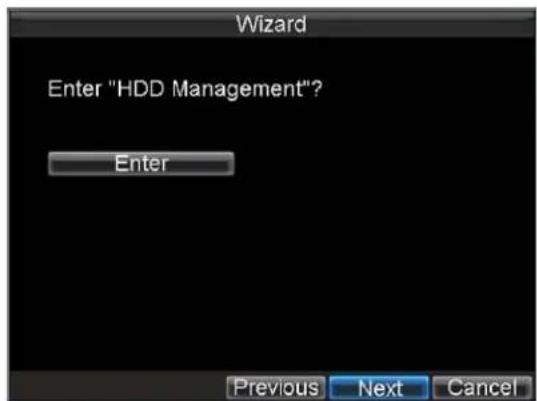

Figure 6. HDD Management
-
To access HDD management interface, click the Enter button.
-
If a new HDD has been recently installed, select the HDD from the list to initialize it. Initializing the HDD will format and remove all data from it.
-
After the HDD has been initialized, click the OK button which will take you back to the Setup Wizard window.
-
Click Next button to enter the Record Settings dialog box, as shown in Figure 7.


Figure 7. Record Settings
-
To access Record Settings interface, click the Enter button.
-
Select the Schedule tab, shown in Figure 8.

Figure 8. Schedule Settings
Note: The Command (Cmd) recording is supported by DS-8100AH (F) (L) I-ST ATM DVR. Command Record will take effect when there is a cash transaction happening on ATM and trigger recording channel is enabled in the ATM settings.
-
Click Edit button to enter a new recording schedule, shown in Figure 9.
-
Check both the Enable Schedule and All Day checkbox. This will enable the recording schedule and make it record continuously all day.
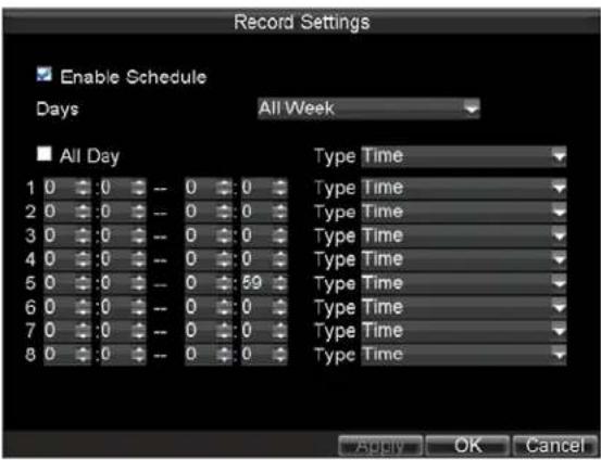
Figure 9. Edit Schedule Settings
- Click the OK button. This will take you back to the Schedule tab. To copy the schedule to a different channel, select the channel or all under Copy To and click the Copy button.
- Click Next button to access the Network Settings dialog box, shown in Figure 10.
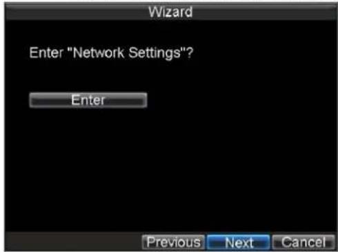
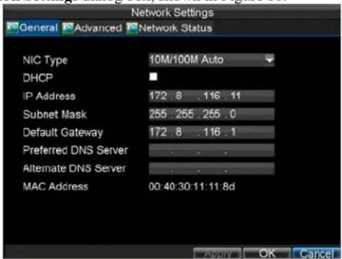
Figure 10. Network Settings
- To configure network settings, click the Enter button.
- Enter the IP Address, Subnet Mask and Default Gateway settings.
- Click OK button to return to the Setup Wizard.
- If all the settings have been entered, click Done to finish and exit the Setup Wizard.
Note: DS-8100AH F (L) I-ST model supports 10M/10M/1000M adaptive Ethernet interface.
You've completed the Setup Wizard. The next step in the initial setup process is to setup the system date and time. After completion of Setup Wizard, enter the Live View window.
Setting Date & Time
It is extremely important to setup the system date and time to accurately timestamp recordings and events.
To setup date and time:
- Open the Menu window by clicking the MENU button on the remote or front panel. You can also go to the Menu window by right clicking with the mouse and clicking the Menu button.
-
Click the Settings icon.
-
Click the General icon. You will be taken to the General Settings window, shown in Figure 11.
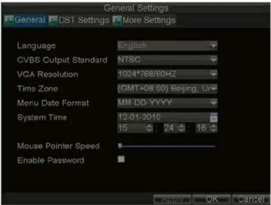
Figure 11. General Settings
- Enter the correct date and time in System Time.
- Click the Apply button to save the setting.
CHAPTER 3
Live Preview
Live Preview On-screen Display
The Live Preview mode is automatically started after the DVR boots up. It is also at the very top of the menu hierarchy, thus hitting the ESC multiple times (depending on which menu you're on) will bring you to the Live Preview mode.
Live Preview Icons
Some icons are provided on screen in Live Preview mode to indicate different camera status. These icons include:

Main Output
Aux Output
Event Alarm: Indicates video loss, video tampering, motion detection or relay alarm.
Record: Indicates the current channel is recording. The recording may have been started manually, from a schedule, and/or triggered from motion or alarm.

Event Alarm & Record: Indicates the current channel is in event alarm & recording status.
Alarm Icon: Indicates there is an alarm or exception.
Figure 1. Live Preview Icons
Note: Status for video loss alarm is only valid with analog cameras.
Live Preview Operation
In Live View mode, you can operate the following functions:
-
Display Single Camera:
-
By Front Panel/Remote: Use Alphanumeric buttons.
-
By Mouse: Select Single Camera in right-click menu.
-
Multi-camera Preview:
-
By Front Panel/Remote: Press PREV button.
-
By Mouse: Select Multi Camera in right-click menu.
-
Manual Switch:
-
By Front Panel/ Remote: Press the Left arrow button to access the previous screen; press the Right arrow button to access next screen.
-
By Mouse: Select Next Screen in right-click menu.
-
Auto Sequence:
-
By Front Panel/Remote: Press Enter button.
-
By Mouse: Select Start Auto-switch in right-click menu.
-
Digital Zoom:
- By Mouse: Select Digital Zoom in right-click menu.
Mouse Operation in Live Preview
Some functions of the Live Preview can be quickly accessed by clicking the right-button of the mouse (shown in Figure 2). These functions include:
- Single Camera: Switch to a full-screen display of the selected camera by drop-down submenu.
- Multi Camera: Switch between different multi-camera display modes by drop-down submenu.
- Next Screen: When displaying less than the maximum number of cameras in Live Preview, select this option to switch to the next camera display.
- Playback: Enter Playback mode of the selected camera.
• PTZ: Enter PTZ Control mode of the selected camera.
• Digital Zoom: Enter Digital Zoom interface of the selected camera. - Menu: Enter Main menu.
- Start Auto-switch: Enable multi-camera sequence in Live Preview mode.
Note: The dwell time of the preview configuration should be set before using Start Auto-switch function.

Figure 2. Live Preview Mouse Menu
Digital Zoom
To use digital Zoom in Live Preview mode:
- Right-click the mouse in Live Preview mode.
- Select Digital Zoom from drop-down submenu.
- Left-click and drag the red box to the desired area for zooming. The zoomed image will be magnified by 4 times. An example is given in the following figure:

natural_image
Scenic highway with cars driving toward a bridge over a mountainous landscape (no visible text or symbols)Figure 3. Digital Zoom
Configuring Live Preview Display
Click Menu >Settings >Display to access the Live Preview display settings:

Figure 4. Display Settings
Configure the following settings for Live Preview Display:
• Video Output: Set the video output modes.
• Mode: Set the live view display mode to be 1 × 1 , 2 × 2 , 3 × 3 , or 4 × 4 .
• Dwell Time: Set the dwell time for camera switching when Start Auto-switch is selected in Live Preview.
• Camera Order: Set the camera order for display in the selected mode (See Setting Camera Order).
- Enable Audio Output: Enable/disable audio output for the selected video output.
• Event Output Port: Set the port for event output.
• Event Dwell Time: Set the dwell time for event video display.
Note:
-
DS-8100AH (F) (L) I-ST model does not provide Aux Output. It will automatically detect whether this is VGA display connected or not. When the VGA is connected and used as the main video output, the VIDEO OUT provides no output; and when the VIDEO OUT is connected and used as the main video output, the VGA provides no output.
-
DS-8100HCI-ST model will automatically detect whether this is VGA display connected or not. When a VGA display is connected to DVR, then the VGA will be used as the main video output, and all menu operations are accessible by mouse, front panel or IR remote; the VIDEO OUT1 will be used as the spot video output which only allows user to access the live view of the camera according to the configured CVBS video parameters; and the VIDEO OUT2 will be used as the auxiliary video output, which allows user to access the single-camera live view of the camera as well as press the 3DEF/F2 button on the front panel to switch the camera display.
When there is no VGA display connected to DVR, the VIDEO OUT1 will be used as the main video output, and menu operations are accessible; the VGA will be used as the spot video output which only allows user to access the live view of the camera according to the configured VGA video parameters; and the VIDEO OUT2 is used as the auxiliary video output which allows user to access the single-camera live view of the camera as well as press the 3DEF/F2 button on the front panel to switch the camera display.
- The connection or disconnection of VGA display in the process of device running will not affect its functions as shown above.
Setting Camera Order
The Camera Order settings allow you to set camera sequence in selectable live view display mode. See the following figure:
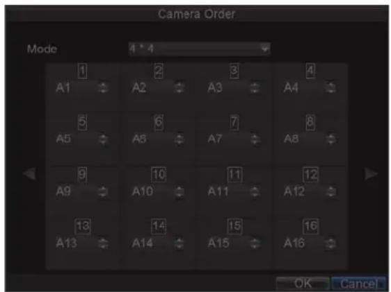
Figure 5. Camera Order Settings
Operate the following steps to set camera order:
- Enter the Display Settings menu (Menu > Settings > Display) and click Set in the Camera Order item.
- Select the video output port and the display mode (1×1, 2×2, 3×3 and 4×4 modes selectable).
- Use the direction buttons on front panel to move to the display pane for setting press the Enter button to confirm the selection.
- Use the direction buttons on front panel to select the camera you want to be view in the display pane. The option ‘×’ indicates no display of camera.
- Press Enter button to confirm the selection.
CHAPTER 4
Record Settings
Configuring Record Settings
There are multiple ways to set up your DVR for recording, including setting up a recording schedule, triggering a recording by motion detection and/or a sensor alarm, and manually starting the recording. In addition, DS-8100 AH (F) (L) I-ST also supports the command triggered recording.
Before Record Settings
Before configuration, please make sure your DVR has been installed with HDD and has completed its initialization, otherwise, access Menu > HDD Management to install the HDD and perform initialization first.
Note: Please refer to Initializing HDD for specific instructions for initializing HDD.
Initializing Record Settings
- Click Menu > Settings > Record to access the Record Settings dialog box, shown in Figure 1.

Figure 1. General Record Settings
- Select the camera you want to configure.
-
Configure the following settings:
-
Encoding Parameters: Set the encoding parameters to be Normal or Event.
- Stream Type: Set the stream type to be Video or Video & Audio.
- Resolution: Set recording resolution.
- Bit Rate Type: Set the bit rate type to be Variable or Constant.
• Video Quality: Set the video quality of recording, with 6 levels configurable.
• Frame Rate: Set the frame rate of recording. -
Max Bit Rate: Select or customize the maximum bit rate for recording.
-
Click the Set button under More Settings to configure more recording settings, as shown in Figure 2.

Figure 2. More Record Settings
- Pre-Record: Set the time in seconds to pre-record before the actual recording begins.
• Post-Record: Set the time in seconds to post-record after the actual recording has ended. - Recording Expired Time: Set the expiration time in days for recorded video. Record files after expiration time will be deleted. If it is set to '0,' record files will not be option would be deleted. The actual period for record files storage is determined by the available HDD space.
- Redundantly Record: Select to enable or disable redundant recording on the particular channel.
-
Record Audio: Enable or disable audio record of the selected camera. Click OK to finish settings and return to the previous menu.
-
Press the 3DEF/F2 button on DVR front panel to select the Advanced tab to access the Advanced Settings submenu, shown in Figure 3.
-
Enable or disable the Overwrite setting. Enabling the Overwrite setting will cause recorded files to be overwritten once the HDD is full.
- Select the usage of eSATA interface to Record or Export.
Note: DS-8100 AH (F) (L) I-ST does not provide eSATA.
- Click Apply and then OK to back to the previous menu.
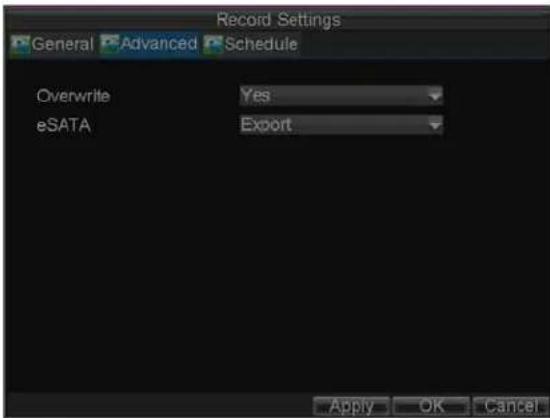
Figure 3. Advanced Record Settings
Scheduling a Recording
The Schedule allows you to set up flexible recording schedules for daily or weekly recording. To set up a recording schedule:
- Click Menu > Settings > Record to enter the Record Settings menu.
- Select the Schedule tab to enter the Schedule dialog box, shown in Figure 4.
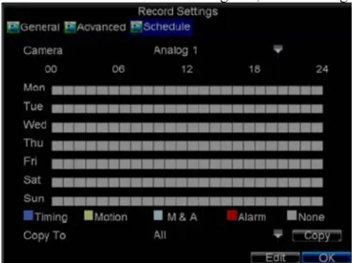
Figure4. Scheduling a Recording
- Select Camera you want to configure recording schedule.
- Click the Edit button to enter the Schedule Settings dialog box.
- Click and check Enable Schedule checkbox.
- Select the day you want to set up the schedule or select All Week to record for entire week.
- Click All Day to enable recording for entire day, or select different periods for each day. Up to 8 time periods can be scheduled.
Note: The time periods scheduled cannot be overlapped with each other. - Select recording Type. Recording type can be selected to scheduled or triggered by motion detection and/or alarm. For more specific settings about motion detection and alarm recordings, please refer to the Configuring Alarms.
- Click the OK button to finish configuration.
- Repeat Steps 3-9 for other cameras or copy settings from one schedule to the others under the Copy To item.
- Click OK to finish configuration and save the schedule settings.
Note: The Command (Cmd) recording is supported by DS-8100AH (F) (L) I-ST ATM DVR. Command Record will take effect when there is a cash transaction happening on ATM and trigger recording channel is enabled in the ATM settings.
Note: The Event encoding parameters will take effect when motion detection or alarm happens, and the Timing encoding parameters will take effect when there are no events happening.
Starting a Manual Recording
A manual recording can be enabled at any time by means of the following configuration:
- Press the REC button on the front panel to access the Manual Record dialog box, shown in Figure 5.
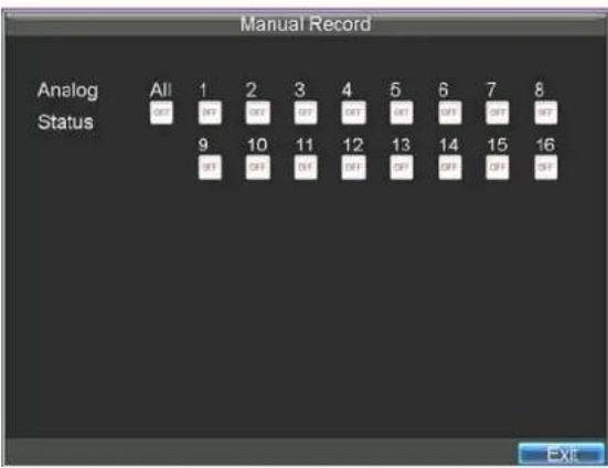
Figure 5. Manual Record Menu
- Start manual recording by selecting ON or OFF for each camera.
Protecting Recorded Files
Two methods are provided to prevent recorded files from being deleted from the HDD or overwritten during cycle recording: set the recorded files to be locked or set the HDD that the files reside on to be read-only.
Locking/Unlocking Recorded Files
To lock or unlock a recorded file:
- Click Menu > Video Search to enter the Video Search dialog box, shown in Figure 6.

Figure 6. Video Search Menu
-
Search for desired recording by entering search parameters. Search parameters include Camera ID, Video/File Type, and Start/End Time.
-
Click the Search button. A list of record files (see Figure 7) matching the search parameters will be
displayed.
-
Select the file you want to lock/unlock.
-
Click the Lock button to lock file. If the file is already locked, click the Unlock button to unlock file. Locked files will be shown with a closed lock while unlocked files, opened lock.
-
Click Cancel to exit the Video Search menu.

Figure 7. Video Search Result List
Setting HDD to Read-Only
To set a HDD to read-only:
- Click Menu > HDD to access the HDD Management dialog box, shown in Figure 8.

Figure 8. HDD Management Menu
- Select the General tab.
- Select the HDD to set to read-only.
- Click the Property button to enter the Property Settings dialog box, shown in Figure 9.

Figure 9. HDD Property Settings Menu
- Set HDD Status to Read-only and then click OK to finish the setting.
Note:
- Once set to read-only, the HDD cannot be written to until it is set back to read/write (R/W).
- When the property is set to read-only, the recording of the device will be stopped.
Configuring Advanced HDD Settings
Setting up HDD Redundancy
To insure unexpected failures of hard disk drives, it's recommended to set up HDD redundancy. It is important to note that in order to set up HDD redundancy, you'll need more than one HDD in your DVR.
To set up HDD redundancy:
- Navigate to the HDD Management menu by clicking Menu > HDD management.
- Click on the General tab.
- Select the HDD to be used for redundancy, as shown in Figure 10.

Figure 10. HDD Management Menu
- Click the Set button. This will take you to the HDD Settings menu.
- Set HDD Status to Redundancy, shown in Figure 11. Verify at least one other HDD is set to R/W (read/write).
- Click the OK button to save settings and return to the previous menu.
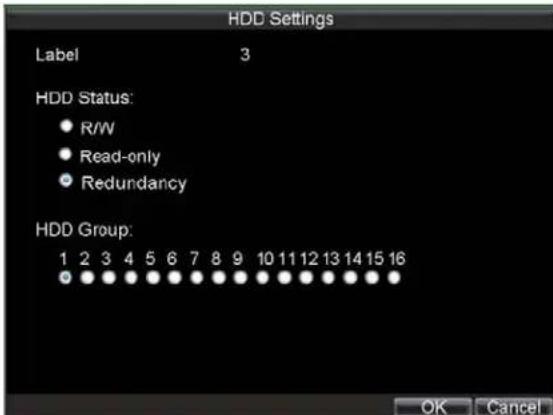
Figure 11. HDD Settings
- Navigate to the Record Settings menu by clicking Menu > Settings > Record Setting.
- Click on the General tab.
- Select the Camera to be used for redundancy.
- Next to More Settings, click on the Set button. This will bring up additional settings for the selected camera (shown in Figure 12).

Figure 12. Additional Record Settings
- Set Redundantly Record to Yes.
- Click the OK button to save settings.
- Repeat steps 8-12 for other cameras you would like to redundantly record.
CHAPTER5
Playback
Video Playback
The Client application allows all users to play back record files of the specified period. Multi-camera simultaneous playback is supported.
Playback Interface
Multiple toolbar and buttons are provided on the playback interface to control the video playback. Refer to the following figure:

Figure 1. Playback Interface
The Playback Control Panel, as shown in Figure 2, provides various control buttons for video playback.

Figure 2. Playback Control Panel
Note: A blue bar ■ refers to the Normal recording (scheduled, manual), while the red bar ■ indicates Event recording.
Playback by Video Search
To play back record files by video search:
-
Enter the Video Search menu by clicking Menu > Video Search.
-
Set the search parameters by selecting cameras to search, video/file type and the start/end time (as shown in Figure 3).

Figure 3. Video Search Menu
- Click the Play button on the front panel to start playback of all the files found, or click the Search button to access the list of search results. After search results are presented, select the file you want to play back and press Play button.
- Record files will automatically be played back in the Playback interface, shown in Figure 4.

Figure 4. Playback Interface
Playback by Event Search
To playback files from a video event search:
- Enter into the Video Search menu by clicking Menu > Event Search
- Set the search parameters by selecting event type to search, alarm input/ channel and the start/end time (as shown in Figure 5).
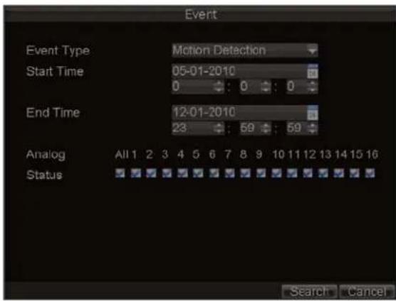
Figure 5. Video Event Search Menu
- Click the Search button to start bring up the list of search results. After search results are presented, you can press play icon to playback the selected event, show in figure 6.

Figure 6. File Selection Menu
- Recordings will automatically be played back in the Playback interface, shown in Figure 7.

Figure 7. Playback Interface
Playback by Card Number
Note: The playback by card No. is supported by DS-8100AH (F) (L) I-ST model only.
To play back files from a video search:
- Enter into the Video Search menu by clicking Menu > Video Search.
- Set the search parameters by selecting cameras, card no., video/file type and the start/end time to search (as shown in Figure 8).

Figure 8. Video Search Menu
Note: You can search and playback video files by their card numbers.
- Click the Play button to start playback of all the files found with the specified search criteria or click the Search button to bring up the list of search results. After search results are presented, select the file you would like to playback and press Play.
- Recordings will automatically be played back in the Playback interface, shown in Figure 9.
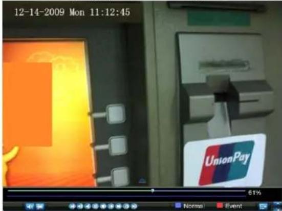
Figure 9. Playback Interface
Playback by Preview Mode
The Client application also allows you to play back record files in Live Preview mode.
To play back by channel in Live Preview mode:
- By Using a Mouse:
- Right-click the mouse on desired channel and select the Playback option.
- Record video from the selected channel will start playing back in the Playback window. An Attention message will appear if there are no recordings found in the previous 5 minutes.
- You may also select additional channels for playback from the channel list on the right side of the Playback interface, as shown in Figure 10.
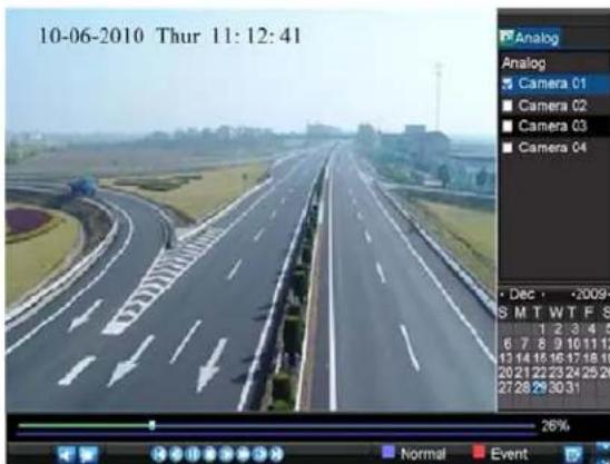
Figure 10. Playback Interface
- By Using the Front Panel/Remote:
- Press the PLAY button on front panel to access the Playback mode.
- Enter the channel you want to view record video from the front panel or remote control (i.e. press 'SHIFT', the STATUS light will turn green, then press '01' for channel 1, press '02' for channel 2).
- Recordings will start for the selected channel.
Note: the record video for playback is of the previous 5 minutes.
- Multi-camera Playback
- Select the cameras from the camera list you want to have simultaneous playback.
- Click to stop the ongoing video playback.
- Click ▶ to start multi-camera simultaneous playback.
Note:
- Up to 16 cameras can be played back simultaneously.
- The camera list operation is accessible by mouse only. Please do not operate by front panel.
- If the camera numbered the lowest among the multiple cameras selected for simultaneous playback provides no record files of the current day selected from the calendar, then the warning message "Playback failed" will be displayed on the screen.
- The video for simultaneous playback by multiple cameras selected from the camera list refers to the all-day record files of the selected day.
Playback by System Log
To play back video from the System Log:
- Click Menu > Maintenance > Log Search to enter the Log Search dialog box, shown in Figure 11.

Figure 11. Log Search Menu
- Set Major Type to Information; set Minor Type to Start Record or End Record; and then select the Start Time and End Time as well. Click the Search button.
- Click the Search button. A list of search results will be displayed. Select the video log to play back and click Play.
- The selected recording then will begin to play in the Playback interface.
Playback Frame-by-Frame
To play back frame-by-frame in the Playback interface:
- By Using a Mouse:
- Click the Slow Forward button on the Playback Control Panel until the speed changes to Single frame.
- Click the Pause button to advance the video frame by frame.
- By Using the Front Panel/Remote Control:
- Press the Down button to select the playback speed to Single frame.
- Press the Enter button to advance the video frame by frame.
Digital Zoom
To use digital zoom in Playback mode:
- Right click the mouse in Playback mode.
- Select Digital Zoom from drop-down submenu.
- Left click and drag the red box to the desired area for zooming. The zoomed image will be magnified by 4 times. An example is given in the following figure:

Figure 12. Digital Zoom in Playback Mode
CHAPTER 6
Backup
Backing up Recorded Files
Recorded files can be backed up to various devices, such as USB flash drives, USB HDDs or a DVD writer.
Exporting Files
To export record files:
- Click Menu > Video Search to enter the Video Search menu, shown in Figure1.
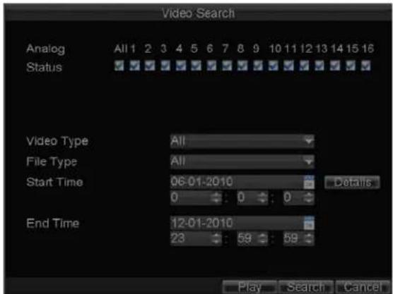
Figure 1. Video Search
- Select desired parameters to search for files to export.
- On the toolbar, press the Export button to enter the Record Backup menu.
- Select the files to export, as shown in Figure 2. You may also click the Play button to confirm the record file you want to export.

Figure 2. Video Search Results
- The size of the currently selected files is displayed at the lower-left corner of the window. Click the Export button to enter the Export menu, shown in Figure 3.

Figure 3. Export Menu
-
Select device to which the record file is exported from drop-down list (USB Flash Drive, USB HDD, DVD Writer). If backup device is not recognized:
-
Click the Refresh button.
- Reconnect device.
-
Check for compatibility from vendor.
-
Click Start to begin backup process, shown in Figure 4.

Figure 4. Backup Progress
- After the backup process has completed (Figure 5), you may select the files from your device and click the Play button to verify that it has been exported successfully.

Figure 5. Successful Export
Note: Video Player software will automatically be copied on to the device that the recorded files were exported on.
To export recorded files via Event Search:
- Enter the Event Search menu (shown in Figure 6) by clicking Menu > Event Search.

Figure 6. Event Search Menu
- Set the search parameters by selecting event type to search, alarm input/ channel and the start/end time, then click Search button, this will take you to search results interface.

Figure 7. Event Search Results
- Select the files to export, you may also click the Play icon to verify that these files are indeed the ones you would like to export.
- Press Export button to enter Export menu, then you can export the files following the step 6 to step 8 as above explanation in this chapter.
Exporting Video Clips
You may also select video clips to export directly in Playback status. A maximum of 30 clips can be selected for each channel.
To export video clips during Playback:
- By Using the Mouse:
- Enter the Playback interface (See Video Playback).
- Click the Clip Start/Stop button on the Playback Control Panel, and select the start and end of the video clip during playback.
- Repeat for additional clips.
- Click the Quit Playback button to exit from the Playback interface. You'll then be prompted to save the clips, as shown in Figure 8.

Figure 8. Video Clips Saving Prompt
- Click the Yes button to enter Backup interface or select No to exit Playback interface.
- At the Backup interface, select the Start button to begin the Backup process.
- By Using the Front Panel / Remote:
- Enter the Playback interface (See Video Playback).
- During playback, press the EDIT button to mark start of clip.
-
Press the EDIT button again to mark end of clip.
-
Repeat for additional clips.
- Press the ESC button to exit from the Playback interface. You'll then be prompted to save the clips, as shown in Figure 8.
- Click the Yes button to enter Backup interface or select No to exit Playback interface.
- At the Backup interface, select the Start button to begin the Backup process.
Exporting Files via e-SATA
Note: This section is valid for DS-8100HCI-ST model only.
DVR provides the e-SATA port on the rear panel as an option. You can back up the recorded files via e-SATA port by using external SATA disk.
To export recorded files via e-SATA:
- Enter the Record Settings menu by clicking Menu > Settings > Record
- Click Advanced tab, it will take you to the e-SATA property configuration, as shown in Figure 9, select For Export option in the drop-down list, the DVR will ask for reboot to take effect.
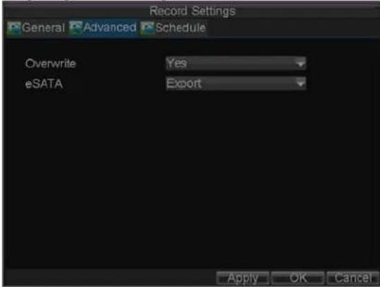
Figure 9. E-SATA Property Settings
- You may go to recorded files export interface following the above explanation in section Exporting Files or Exporting Video Clips. The Export menu appears as shown in Figure 10.

Figure 10. Files Export Interface
- Select a partition in the drop-down list, then you may click Start to start exporting. Wait until the backup process complete.
Managing Backup Devices
To manage backup devices, you must first be in the Export menu, shown in Figure 11. The Export menu can be accessed by following the steps shown in the previous section (See Exporting Files).
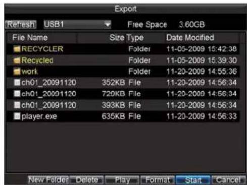

Figure 11. Export Menu
Once in the Export menu, you may:
- Create New Folder: Creates a new folder on the export device.
- Delete: Delete a file or folder from the export device.
• Play: Play the selected video file from the export device. - Format: Format the export device.
- Erase: Erase files from a re-writable CD/DVD.
CHAPTER7
Alarm Settings
Configuring Alarms
Motion Detection Alarm
Operate the following steps to configure Motion Detection Recording:
1. Enter Camera Setting:
Click Menu > Settings > Camera to access the Camera Settings menu, as shown in Figure 1.
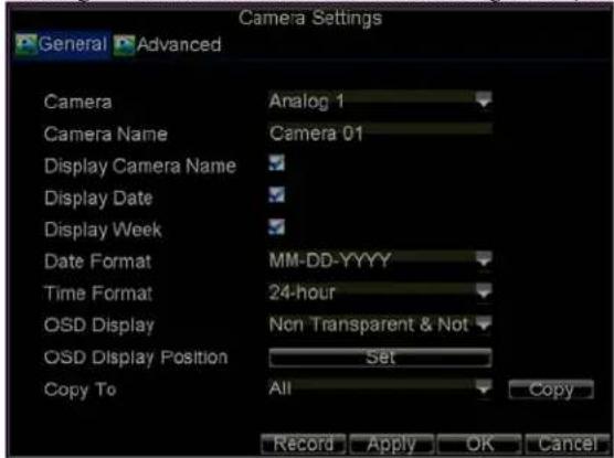
Figure 1. Camera Settings Interface
- Select the Advanced tab to enter the Advanced Camera Settings menu, shown in Figure 2.

Figure 2. Advanced Camera Settings
-
Select Motion Detection first and click the Area Settings button to enter the Motion Detection Area and Sensitivity settings interface.
-
As shown in Figure 3, the Motion Detection area allows you to mask areas you want to configure
motion detection. The maximum area can be set to be full screen. You can left click mouse, hold and drag it to mask the Motion Detection area. Using EDIT button and direction buttons can also help you to select Motion Detection area.

natural_image
Highway with red structural frame overlay, no visible text or symbolsFigure 3. Motion Detection Area
- Right click mouse or press the MENU button on the front panel to set the Motion Detection Sensitivity, shown in Figure 4. Higher sensitivity value corresponds to higher sensitivity level.

Figure 4. Motion Sensitivity Settings
- Click OK to return to the motion detection area settings interface.
- Right click the mouse to select the Exit from the menu to return to the Advanced Camera Settings menu.
- Click the Handle button to enter the Exception Handle menu, shown in Figure5.

Figure 5. Triggered Camera Settings
- Select cameras to trigger for recording when motion is detected by checking the checkboxes under the desired cameras.
- Select the Schedule tab. Set the schedule you want motion detection to be enabled. Schedule can be set for all week or any day of the week with up to 8 time periods per day.
Note: After having configured the schedule, the DVR must be restarted for the new settings to take effect.
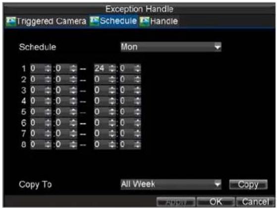
Figure 6. Schedule Settings for Motion Detection
- Select the Handle tab to configure exceptions handling. Exception trigger options will be described in the next section (See Understanding Exception Trigger Options).
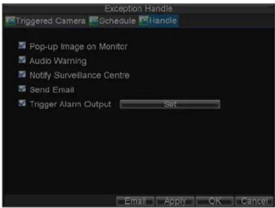
Figure7. Exception Handle Menu
- Click OK to complete motion settings for the selected camera.
You may now add a schedule to start recording when motion is detected (See Scheduling a Recording).
Sensor Alarm Settings
Recordings can also be triggered from an external relay alarm device. To set up sensor alarms:
- Click Menu > Settings > Alarm to enter the Alarm Settings menu, shown in Figure 8.
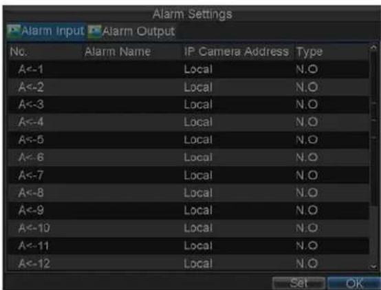
Figure 8. Alarm Input Interface
Note: 4 alarm inputs are provided for DS-8104HCI-ST and 9 alarm inputs for DS-8100AH (F) (L) I-ST model.
- Select the Alarm Input No. and click the Set button to enter the Alarm Input Settings menu, shown in Figure 9.

Figure 9. Alarm Management Settings
- Set the alarm input type to be Normally Opened (N.O) or Normally Closed (N.C).
- Check the checkbox next to Setting and click the Handle button to enter the Alarm Input Handle menu.
- Select the Triggered Camera tab.
- Select cameras to trigger for recording when alarm occurs by checking the checkboxes under the desired cameras, as shown in Figure 10.
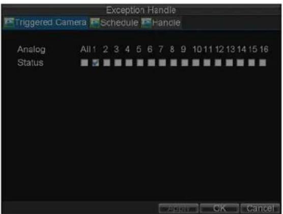
Figure 10. Triggered Camera Menu
- User may select the PTZ camera to link with the alarm input and then set the callup of preset, patrol and pattern for alarm linked actions.
- Click the OK button to complete setup.
You may now add a schedule to start recording when an alarm is triggered (See Scheduling a Recording).
Alarm outputs may also be configured in the Alarm Management menu. To set up Alarm Output:
- Select the Alarm Output tab. This will bring up the Alarm Output interface, shown in Figure 11.

Figure 11. Alarm Output Interface
Note: 2 alarm outputs are provided for DS-8104HCI-ST model.
- Select the output you would like to configure and click the Set button. This will bring up the settings page for the selected channel (Figure 12).
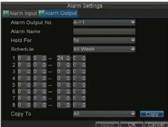
Figure 12. Alarm Output Settings
- Configure the settings for selected output.
- Select OK to save and exit.
Note: If the Hold For option is selected as Manually Stop, the alarm will only stop when you manually stop it (See Triggering Alarm Outputs Manually).
Manual Alarm Triggering
You may also trigger alarm outputs manually through the Manual Alarm menu.
To trigger alarm outputs manually:
- Click Menu > Manual Alarm to enter the Manual Alarm menu (Figure 13).

Figure 13. Manual Alarm Menu
-
Configure the following settings in the Manual Alarm menu:
-
Trigger: Select an alarm from the list and click Trigger to trigger its output.
- Trigger All: Trigger all alarm outputs at once.
-
Clear All: Stop all alarm outputs at once.
-
Select OK to return to the previous menu.
Video Loss Detection
Your DVR can be set up to detect video loss and trigger an action. To set up video loss detection:
- Click Menu > Settings > Camera to enter Camera Settings menu, shown in Figure 14.
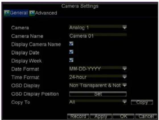
Figure 14. Camera Settings Menu
- Select the Advanced tab.
- Select the camera to be configured with video loss detection.
- Check the Video Loss Detection checkbox to enable this feature, as shown in Figure 15.
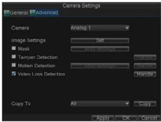
Figure 15. Camera Settings Menu
- Click the Handle button to enter the Exception Handle menu, shown in Figure 16.
- Select the Schedule tab. Set the schedule you want video loss detection to be enabled. Schedule can be set for all week or any day of the week with up to 8 time periods per day.
Note: After having configured the schedule, the DVR must be restarted for the new settings to take effect.

Figure 16. Schedule Settings for Video Loss Detection
- Select the Handle tab to configure exceptions handling. Exception trigger options will be described in the next section (See Understanding Exception Trigger Options).
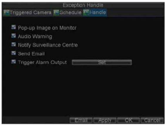
Figure 17. Exception Handle Menu
- Click OK to finish the settings.
- Repeat above steps to configure settings for other channels.
Video Tampering Detection
The video tampering can also be detected and set to trigger an action on your DVR. To set up video tampering detection:
- Click Menu > Settings > Camera to enter the Camera Settings menu, shown in Figure 18.
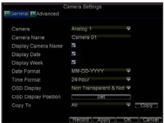
Figure 18. Camera Management Menu
- Select the Advanced tab.
- Select the camera to be configured with video tampering detection.
- Check the Tamper Detection checkbox to enable this feature, as shown in Figure 19.

Figure 19. Camera Settings Menu
Note: The DS-8100AHF (L) I-ST model supports the area settings for tamper detection. Please refer to the motion detection area or privacy mask settings sections for the instructions.
- Click the Handle button to enter the Exception Handle menu, shown in Figure19.
- Select the Schedule tab. Set the schedule you want video loss detection to be enabled. Schedule can be set for all week or any day of the week with up to 8 time periods per day.
Note: After having configured the schedule, the DVR must be restarted for the new settings to take effect.

Figure 20. Schedule Settings for Video Tampering Detection
- Select the Handle tab to configure exceptions handling. Exception trigger options will be described in the next section (See Understanding Exception Trigger Options).

Figure 21. Exception Handle Menu
- Click OK to finish the settings.
- Repeat above steps to configure settings for other channels.
Exception Settings
The exception setting allows the DVR to alert you when irregular events occur. These events include:
• HDD Full: All installed HDD are full.
- HDD Error: Errors occurred during writing of the HDD, no HDD installed or HDD had failed to initialize.
• Network Disconnected: Disconnected network cable.
• IP Conflicted: Conflict in IP address setting.
- Illegal Login: Incorrect user ID or password used.
• Video Output Standard Mismatch: video output standards do not match with each other.
• Abnormal Recording: No recording HDD.
To set exceptions:
- Click Menu > Settings > Exception to enter the Exception menu.
- Select the exception to configure under Exception Type.
- Select triggering options, as shown in Figure22. Trigger options are further explained in the next section (See Understanding Exception Trigger Options).

Figure 22. Exception Menu
- Click OK to save settings and exit Exception menu.
Understanding Exception Trigger Options
When setting up exception handlers for such features as motion detection and relay alarms, you may select triggering options to alert you of these exceptions.
The triggering options that you may select include:
- Pop-up Image on Monitor: When an alarm is triggered, the local monitor (VGA or BNC monitor) will display an image in Live Preview mode. This alarm can be configured under the Popup Alarm Image handle method. For alarms that are triggered simultaneously, images will be displayed one at a time every 10 seconds (default dwell time). A different dwell time can be set by going to Menu > Setting > Display > Dwell Time. Once the alarm stops, cycling of the images will also stop and you'll be returned to the Live Preview screen.
- Audio Warning: Trigger an audible beep when exception is detected.
- Notify Surveillance Centre: Sends a signal to remote alarm host when exception is detected (See
Configure Remote Alarm Host).
- Trigger Alarm Output: Trigger an alarm output when exception is detected. Alarm output can be configured by following the steps listed in Setting up Sensor Alarms.
CHAPTER8
Network Settings
Configuring Network Settings
Network settings must be configured if DVR is used for monitoring over network.
General Settings
To configure general network settings:
- Click Menu > Settings > Network to enter the Network Settings menu, shown in Figure 1.
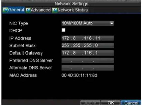
Figure 1. Network Settings Menu
-
Select the General tab. Configure the settings on the interface.
-
If you have a DHCP server running and would like your DVR to automatically obtain an IP address and other network settings from that server, check the DHCP checkbox. You may check the DHCP status by going to the Network Status tab, as shown in Figure 2.

Figure 2. Network Status
- If you want to configure your own settings, enter the settings for:
- IP Address: IP address you would like to use for your DVR.
- Subnet Mask: Subnet Mask of network.
- Default Gateway: IP address of your Gateway. Typically the IP address of your router.
- Preferred/Alternate DNS Server: The preferred and alternate Domain Name System (DNS) Server to be used with your DVR.
- Click OK to save settings and exit the Network Settings menu.
PPPOE Settings
Your DVR also allows for Point-to-Point Protocol over Ethernet (PPPOE) access. To set up PPPOE access:
-
Click Menu > Settings > Network to enter the Network Settings menu.
-
Select the General tab, as shown in Figure 3.

Figure 3. Network Settings Menu
- Select the Advanced tab to enter the Advanced Network Settings menu, shown in Figure 4.

Figure 4. Advanced Network Settings
- Click the Set button next to PPPOE to enter PPPoE Settings menu, shown in Figure 5.

Figure 5. PPPoE Settings
-
Check the PPPOE checkbox to enable this feature.
-
Enter User Name, Password, and Confirm Password for PPPOE access. PPPOE credentials can be obtained from your network administrator. Once the setup is completed, your DVR will automatically dial-up into your network after reboot.
-
Click OK to save settings and exit Network Settings menu. You may be now asked to restart your DVR for settings to take place. To check on the status of your PPPoE connection, go to Menu > Setting > Network and select the Network Status tab.
DDNS Settings
If your DVR is setup to use PPPoE as its default network connection, you may set up Dynamic DNS (DDNS) to be used in connection.
To set up DDNS:
- Click Menu > Settings > Network to enter the Network Settings menu.
- Select the Advanced tab.
- Select the Set button next to DDNS to enter the DDNS settings menu, shown in Figure 6.
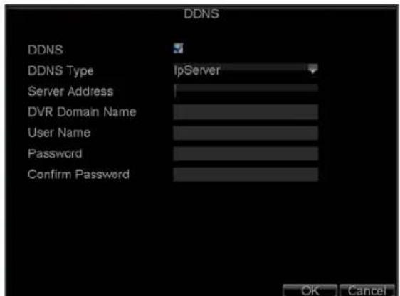
Figure 6. DDNS Settings Menu
-
Check the DDNS checkbox to enable this feature.
-
Select DDNS Type. Three different DDNS types are selectable: IpServer, PeanutHull and DynDNS.
-
IpServer: Enter Server Address for IpServer. Refer to Figure6.
- PeanutHull: Enter User Name and Password obtained from the PeanutHull website (Figure 7).
- DynDNS: Enter Server Address for DynDNS (i.e. members.dyndns.org). Under DVR Domain Name, enter the domain obtained from the DynDNS web site. Finally, enter the User Name and Password registered in the DynDNS network.
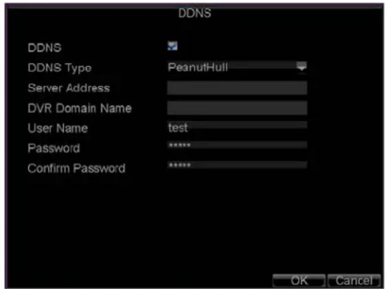
Figure 7. DDNS Settings
NTP Server Settings
A Network Time Protocol (NTP) Server may also be set up on your DVR to maintain accurate current date and time.
To set up an NTP server:
- Click Menu > Settings > Network to enter the Network Settings menu.
- Select the Advanced tab.
- Click the Set button next to NTP to enter the NTP Settings menu, as shown in Figure 8.

Figure 8. NTP Settings Menu
- Check the NTP checkbox to enable this feature.
- Configure NTP settings:
- Synchronize Interval: Time in minutes to synchronize with NTP server.
• NTP Server: Address of NTP server.
Note: The address can be set to the IP address or the Domain name. When the Domain name is used, please set the DNS server address.
- Click OK to save settings and exit the NTP Settings menu.
Note: Time synchronization interval has a range of 0-10080 min, normally 7200 min. If the DVR is used on a public network, you should use a NTP server that has a time synchronization function, such as the server at the National Time Center (IP Address: 210.72.145.44). If the DVR is setup in a more customized network, NTP software can be used to establish a NTP server used for time synchronization.
Remote Alarm Host Settings
With a remote alarm host set, the DVR will send a signal to the host when an alarm is triggered. The remote alarm host must have the Network Video Surveillance software installed.
To set up a remote alarm host:
- Enter Network settings menu by clicking Menu > Setting > Network.
- Select the Advanced tab.
- Click the Set butt next to Host/Others to enter the Host/Others menu, as shown in Figure 9.

Figure 9. Host/Others Menu
- Enter Alarm Host IP and Alarm Host Port. Alarm Host IP is the IP of the remote PC which has the Network Video Surveillance software installed. The Alarm Host Port must be the same as software's alarm monitor port (default port is 7200).
Multicast Settings
Setting up multicasting solves limitation issues when streaming videos through a network access device. A multicast address spans the Class-D IP range of 224.0.0.0 to 239.255.255.255. It is recommended to use the IP address range from 239.252.0.0 to 239.255.255.255.
To set up multicast:
- Click Menu > Settings > Network to enter the Network Settings menu.
- Select the Advanced tab.
-
Click the Set button next to Host/Others to enter the Host/Others menu.
-
Set Multicast IP, as shown in Figure 10. When adding a device to the Network Video Surveillance software, the multicast address must be the same with the DVR's multicast IP.
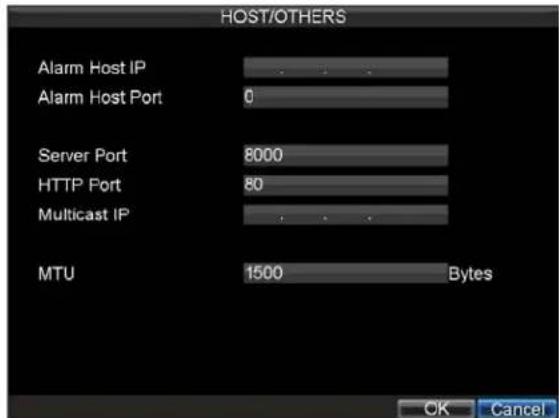
Figure 10. Host/Others Menu
- Click OK to save settings and exit the Host/Others menu.
Server and HTTP Ports Settings
If you would like to change the server and HTTP ports from the default settings, you can do so in the Network Settings menu. The default server port is 8000 while the default HTTP port is 80.
To change the default ports:
- Click Menu > Settings > Network to enter the Network Settings menu.
- Select the Advanced tab.
- Click the Set button next to Host/Others to enter the Host/Others menu.
- Enter new Server Port and HTTP Port, as shown in Figure 11.

Figure 11. Host/Others Menu
Note: The Server Port has a port range of 2000-65535 and is used for remote client software access. The HTTP port is used for remote Internet browser access.
E-mail Settings
To configure E-mail settings:
- Enter the Network Settings menu by clicking Menu > Setting > Network.
- Select the Advanced tab.
- Click the Set button next to E-mail to enter the E-mail menu. The E-mail menu is shown in Figure 12.
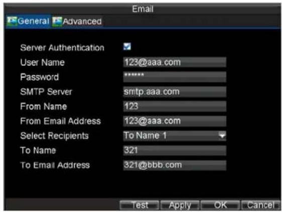
Figure 12. E-mail Menu
- Enter e-mail settings. Please refer to Figure 12 for details.
- Click the Test button to test e-mail settings.
- Select Advanced tab to enable Attached Image File if you want to send email with alarm images, the interval is the time of two adjacent alarm images. You can also set SMTP port and enable SSL here.
- Click the OK button to save and exit the E-mail menu.
Note: It is recommended that the e-mail settings be tested after they are entered. This can be accomplished by clicking the Test button in the E-mail menu.
CHAPTER9
PTZ Control
PTZ Menu
PTZ menus can be navigated through with either the mouse or the front panel/remote. For quick access to certain PTZ settings, right clicking with the mouse in a display while in PTZ control mode will enter the PTZ settings menu. This menu is shown in Figure 1.

Figure 1. PTZ Settings Menu
The items that can be found on this menu include:
• Camera: Select a PTZ camera.
- Call Preset: Call a PTZ preset.
• Call Patrol: Call a PTZ sequence.
- Call Pattern: Call a PTZ pattern.
• Preset Settings: Enter PTZ preset configuration menu.
• Patrol Settings: Enter PTZ sequence configuration menu.
• Pattern Settings: Enter PTZ pattern configuration menu.
• PTZ Menu: Enter PTZ control menu.
• PTZ Settings: Enter PTZ settings menu.
PTZ Settings
Settings for a PTZ camera must be configured before it is used. Before proceeding, verify that the PTZ and RS-485 of the DVR are connected properly.
To configure PTZ settings:
- Click Menu > Settings > PTZ to enter the PTZ Settings menu, shown in Figure 2.
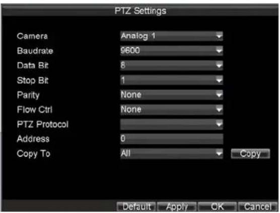
Figure 2. PTZ Settings Menu
- Select channel where PTZ camera is installed next to Camera label.
- Configure the settings of baud rate, data bit, stop bit, parity, flow control, PTZ protocol and address.
- Click OK to save settings and exit the PTZ Settings menu.
Note: All setting parameters (baud rate, data bit, stop bit, parity, flow control, PTZ protocol and address) must be consistent with the PTZ camera connected.
Setting PTZ Presets, Patrols & Patterns
The DVR allows you to program presets, patrols and patterns for a connected PTZ camera.
Understanding PTZ Control
The PTZ control panel provides a series of PTZ controls, shown in Figure 3.
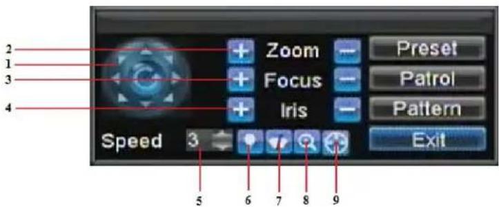
Figure 3. PTZ Control Interface
The controls on the PTZ panel include:
- Directional Pad/Auto-scan Buttons: Controls the movements and directions of the PTZ. The center button is also used to start auto-scan of PTZ.
- Zoom: Used to zoom in and out with the PTZ.
-
Focus: Used to adjust the focus of the PTZ.
-
Iris: Used to open up or close the iris of the PTZ.
- Speed: Adjusts the movement speed of the PTZ.
- Light: Turns PTZ light (if applicable) on and off.
- Wiper: Turns PTZ wiper (if applicable) on and off.
- Zoom In: Instantly zooms PTZ in.
- Center: Centers PTZ.
Setting Presets
Presets can be set to move your PTZ camera to a desired preset location.
To set up and call custom PTZ presets:
- Enter the PTZ Control interface, shown in Figure 3, by selecting PTZ from the mouse menu or clicking the PTZ button on the front panel.
- Select the Preset button to enter the Preset Management menu.
- In the Preset Management menu, shown in Figure 4, you may:
- Configure Preset: Use the PTZ control panel to adjust the position of the preset. Select a Preset number and click the Set button to save preset location.
- Clear Preset: Select a Preset number and click the Clear button to delete the preset. You may also select the Clear All button to delete all presets.
- Call Preset: Select a Preset and click the Call button.

Figure 4. Preset Management Menu
Note: Only valid presets can be called and deleted.
Setting Patrols
Patrols can be programmed to move the PTZ to different key points and make it stay there for a defined duration before moving on to the next point. The key points are defined by presets which can be set by following the steps above in Customize Presets.
To set up and call PTZ patrols:
-
Enter the PTZ Control interface, shown in Figure 3, by selecting PTZ from the mouse menu or clicking the PTZ button on the front panel.
-
Select the Patrol button to enter the Patrol Management menu, shown in Figure 5.
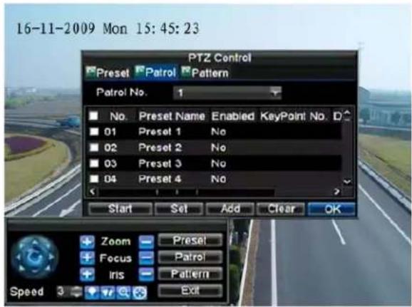
Figure 5. Patrol Management Menu
- In the Patrol Management menu, you may:
- Configure Patrol:
- Select a Patrol Number to set.
- Select valid presets (See Customize Presets) and click the Set button to enter the Patrol configuration menu. A sequence should have at least 2 valid presets.
- Set the Key Point No., Duration, and Speed (Figure 6). The Key Point No. determines the order at which the PTZ will follow while cycling through the patrol. The Duration refers to the time span to stay at the corresponding key point. The Speed defines the rate at which the PTZ will move to the current preset.

Figure 6. Patrol Configuration Menu
- Click OK to return to Patrol Management menu and repeat steps 2-3 to configure other key points.
- After all key points have been configured, click the defined key point No. and then click Add button to complete the settings.
- Click OK button to save settings and exit the current menu.
- Clear Patrol:
- Select a valid Patrol Number.
- Click the Clear button to delete patrol.
- Call Patrol:
-
Select a valid Patrol Number.
-
Click the Start button to call the patrol, and select the Stop button to stop the patrol, as shown in Figure 7.

Figure 7. Patrol Management Menu
Setting Patterns
Patterns can be setup by recording the movement of the PTZ.
To set up and call PTZ patterns:
- Enter the PTZ Control interface, shown in Figure 3, by selecting PTZ from the mouse menu or clicking the PTZ button on the front panel.
- Select the Pattern button to enter the Pattern Management menu, shown in Figure 8.

Figure 8. Pattern Management Menu
- Select a Pattern Number.
- To record a new pattern, select the Run Record button to start recording of the movements of the PTZ. Use the PTZ control panel to move the PTZ. The PTZ movements will be recorded until the Stop Record button is clicked.
- To run a pattern, click the Run Pattern button on a valid pattern. The PTZ will move according to the path that was defined until Stop Pattern is clicked.
- Click OK to exit the current menu.
CHAPTER10
Camera Management
OSD Settings
On Screen Display (OSD) settings can be configured in the Camera Management menu. The OSD is shown in each display during Live Preview mode and includes the time and date as well as the camera name.
To configure OSD settings:
- Click Menu > Settings > Camera to enter the Camera Settings menu, shown in Figure 1.
- Select channel to set up OSD settings under Channel No., and click the Set button.
- Configure desired OSD settings, as shown in Figure1.

Figure 1. OSD Settings Menu
- Click the Set button to edit the OSD display position, including the camera name position and the date/time display position.
Display Settings
Display settings such as the brightness, contrast, saturation and hue can also be adjusted in the Camera Management menu.
To adjust display settings:
- Click Menu > Settings > Camera to enter the Camera Settings menu, shown in Figure 1.
- Click the Advanced tab to enter the Advanced Camera Settings menu, as shown in Figure1. Select channel for image settings in Camera.
- Click the Set button next to the Image Settings label.
- Adjust the display settings, as shown in Figure 3. Brightness, contrast, saturation and hue can be adjusted in the menu. The adjustments of display settings will affect the live images and the recorded images.

Figure 3. Display Settings
Privacy Mask Settings
You may setup privacy mask to mask off sensitive or private areas in the field of view of a camera.
To setup privacy mask:
- Click Menu > Settings > Camera to enter the Camera Settings menu.
- Click the Advanced tab to enter the Advanced Camera Settings menu, as shown in Figure1. Select channel for privacy mask settings in Camera.

Figure 1. Advanced Camera Settings Menu
- Check the Mask checkbox to enable feature.
- Click the Area Settings button to enter Area Settings menu.
- Set mask area, as shown in Figure2. Up to 4 areas can be set.
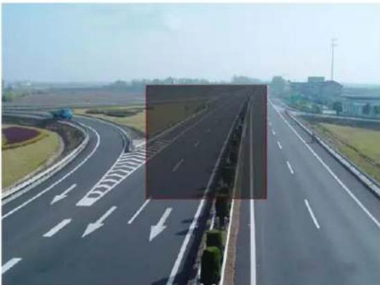
natural_image
Highway with curved road markings and directional arrows, no visible text or symbolsFigure2. Setting Mask Area
- Select Exit to save settings and exit the Mask Area Settings interface.
CHAPTER11
HDD Management
Managing HDDs
Initializing HDDs
A newly installed hard disk drive (HDD) must be first initialized before it can be used with your DVR. Initializing the HDD will erase all data on it.
To initialize a HDD:
- Click Menu > HDD to enter the HDD Management menu, shown in Figure 1.
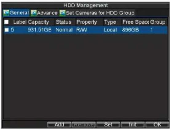
Figure 1. HDD Management Menu
- Select HDD to be initialized.
- Click the Init button.
- Select OK button to start initialization. After the HDD has been initialized, the status of the HDD will change from Abnormal to Normal.
Setting Network HDD
Add the allocated "DVR Storage Space" of NAS or disk of IP SAN to DVR, this part will work as network HDD.
To set a network HDD:
- Enter the HDD Management menu, shown in Figure 2 by clicking Menu > HDD.
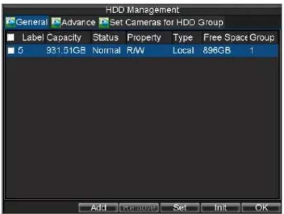
Figure 2. HDD Management Menu
- Click Add to enter Network HDD menu.
- Select type as NAS or IP SAN, shown in Figure 3 when selected as NAS.

Figure 3. Network HDD Menu
- Select Add button to add network HDD to HDD list.

Figure 4. HDD Management Menu
- Select the network HDD to initialize. After initialization, the network HDD can be used.
Setting HDD Groups
Your DVR can separate multiple HDDs into groups. Videos from specified channels can be set to be recorded onto a particular HDD group.
To setup a HDD group:
- Enter the HDD Management menu by clicking Menu > HDD.
- Select HDDs to be added to group.
- Select Set button to enter HDD Settings menu.
- Set the HDD Group Number, as shown in Figure 5.

Figure 5. HDD Settings Menu
- Select OK to save and exit menu.
Note: By default, all HDDs belong to group 1.
To setup specified channels to be recorded onto a particular HDD group:
- Select Set Cameras for HDD Group tab to enter setup interface.
- Select channels for the group.
- Select the HDD group you want the channels to be recorded on, as shown in Figure 6.
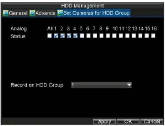
Figure 6. Set Cameras for HDD Group
- Select OK to save and exit menu.
Setting HDD Status
You may change the behavior of your HDD by changing its status. The status of a HDD can be set to redundancy, read-only or read/write (R/W).
Setting HDD to Read-Only
A HDD can be set to read-only to avoid important recorded files from being overwritten when the HDD becomes full.
To set a HDD to read-only:
- Enter the HDD Management menu by clicking Menu > HDD.
- Select HDD to protect.
- Select the Set button to enter the HDD Settings menu, as shown in Figure 7.

Figure 7. HDD Settings Menu
- Set HDD Status to Read-Only.
- Select OK to save and exit menu.
Note: Once set to read-only, the HDD cannot be written to until it is set back to read/write (R/W). If the HDD that is currently being written to is set to read-only, the data will be recorded to the next HDD. If there is only one HDD present, setting it to read-only will cause the DVR to not record.
Setting HDD to Redundancy
In order to use HDD redundancy on your DVR, you will need to have at least two disk installed. Setting up HDD redundancy will allow your DVR to redundantly record a copy of the videos onto multiple drives as a safeguard against losing all your files in case of disk failures.
To set a HDD to redundancy:
- Enter the HDD Management menu by clicking Menu > HDD.
- Select HDD to setup redundancy on.
- Select the Set button to enter the HDD Settings menu, as shown in Figure 7.
- Set HDD Status to Redundancy.
- Select OK to save and exit menu.
Note: The HDD that is set to redundancy is used to store an extra copy of the recording. If a HDD is set to redundancy, at least one HDD should be set to the R/W status.
Checking HDD Status
You may check the status of the installed HDDs on your DVR at anytime.
To check the status of a HDD:
- Click Menu > HDD to enter the HDD Management menu.
- The status of your HDD is listed under the Status column. If the status is listed as Normal or Hibernate, the HDD is in working order. If it is listed as Abnormal and has already been initialized, the HDD needs to be replaced. If the HDD is Uninitialized, you will need to initialize it before it can be used in your DVR. Please refer to Initializing HDDs for further instructions.
You may also view the SMART information of installed HDD SMART, abbreviation for Self-Monitoring, Analysis and Reporting Technology, is a monitoring system for hard disk drives to detect and report on various indicators of reliability in the hopes of anticipating failures.
To view SMART information of a HDD:
- Click Menu > Maintenance > Log Search to enter the Log Search menu, shown in Figure 8.
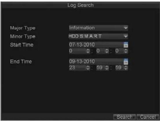
Figure 8. Log Search Menu
- Set Major Type to Information.
- Set Minor Type to HDD SMART.
- Enter Start Time and End Time.
- Click the Search button to begin log search. A list of results, similar to that of Figure 9, will be returned.

Figure 9. Log Search Results
- Select log item to view and click the Details button.
- A detail list of SMART information, as shown in Figure 10, will be displayed.

Figure 10. HDD SMART Information
User can also click Menu > HDD to enter the HDD management menu, as shown in Figure1, and then select the Advance option to enter the SMART menu, as shown in Figure 11. User can enable the SMART function and view the SMART information as well.

Figure 11. HDD SMART Menu
Configuring HDD Alarms
HDD alarms can be set to trigger when an HDD is uninitialized or in an abnormal state.
To set HDD alarms:
- Click Menu > Settings > Exception to enter Exception menu, shown in Figure 12.

Figure 12. Exception Menu
- Select HDD Error under Exception Type.
- Select trigger action. Trigger actions are further explained in Understanding Exception Trigger Options.
CHAPTER 12
ATM Settings
Note: This section is valid for DS-8100AH (F) (L) I-ST ATM DVR.
Network Interception
The Network Interception is used for capturing the card No. and other information by intercepting the data packet through network connection.
- Enter ATM Settings menu, shown in Figure 1 by clicking Menu > Setting > ATM to enter ATM Settings menu.

Figure 1. ATM Settings Menu
- Click the ATM Enable checkbox to enable ATM function, and then select the connection type to Network Interception.
- Click the Set button beside More Settings to enter the ATM Type Settings menu.
- Set the Data Packet in the menu shown in Figure 2: Packet Identification: set the start/end identifier of the packet and identifier type (ASCII/HEX) to determine the identifier position in the message. Data Packet Filter: set the content (ASCII/HEX) and the content position to filter the message, as well as obtain the message containing the filtered content. After completion of Data Packet settings, click the Trading Info item to enter the menu.

Figure 2. Data Packet Menu
- Trading Information Settings, shown as Figure 3: Set the main type, with Card No., Trade Action, Trade Amount and Serial No. selectable. Set the location, length, overlay position of the selected main type. If required, input the characters beside Display Prefix to add a prefix to the selected main type. After completion of Trading Info settings, click the Trigger Channel item to enter the menu.

Figure 3. Trading Info Menu
Note: When the main type is set to Trade Action, user may select the corresponding sub-type, with the InCard, OutCard, Overlay, Query, Withdraw, Deposit, Change Password and Transfer options selectable.
- Set the Location of the main type: Click the Set button beside Location to enter the menu, shown as Figure 4. Select the location of the card No. in the message to Fixed Offset or Token Offset. In token offset mode, user may set the identifier (ASCII/HEX) and extra offset to determine the position of the content in the message, as well as set the multiplier of the identifier.

Figure 4. Location Menu
- Set the Length of the main type: Click the Set button beside Length to enter the menu shown as Figure 5. Set the length of the card No. to Fixed Length, Variable Length or Auto Length. In variable length mode, user may set the End Character to determine the length of the card No. In auto length mode, user may set the length value and position to obtain the card No. length from the message.

Figure 5. Length Menu
Note: No Length can be set if the main type is selected to Trade Action.
- Set the Overlay Position of the main type: This menu, shown as Figure 6, is used for setting the overlay position of the card No., with the X/Y coordinate configurable. If not required, select None to disable this feature.
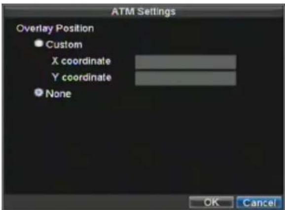
Figure 6. Overlay Position Menu
- Trigger Channel settings: Select the channel for message overlay and record triggering, and time delay for recording if required. After completion of settings, click OK to return to the ATM Settings menu shown as Figure 7 below.

Figure 7. Trigger Channel Menu
Note: If no InCard and OutCard commands are provided by the Trade Action type, please enable the time delay function.
-
In the ATM Settings menu, shown as Figure 1, click the Set button beside Network Interception to enter the network interception settings menu.
-
Set the IP address of ATM, shown as Figure 8 below.
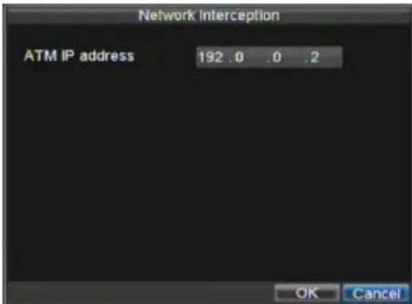
Figure 8. ATM IP address Menu
Serial Interception
The Serial Interception is used for capturing the card No. and other information by intercepting the data from serial port connected.
- Enter ATM Setting menu, shown in Figure 9. Click Menu > Setting >ATM to enter ATM Settings menu.
- Click the ATM Enable checkbox to enable ATM function, and then select the connection type to Serial Interception.
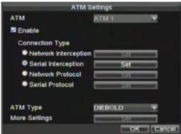
Figure 9. ATM Settings Menu
Note: The Serial Interception and Serial Protocol cannot be selected simultaneously.
- ATM Type Settings, shown in Figure 9. The ATM type can be set to DIEBOLD, DRS918 or NCR_2, or customized by selecting Custom from the list and clicking the Set button beside More Settings to enter the ATM Type Settings menu.
- Set the Data Packet in the menu. Please refer to step2 in section Network Interception for the same instructions. After completion of Data Packet settings, click the Trading Info item to enter the menu.
- Trading Information Settings: Set the main type, with Card No., Trade Action, Trade Amount and Serial No. selectable.
- Set the location, length, overlay position of the selected main type. If required, input the characters beside Display Prefix to add a prefix to the selected main type. After completion of Trading Info settings, click the Trigger Channel item to enter the menu.
Note: When the main type is set to Trade Action, user may select the corresponding sub-type, with the InCard, OutCard, Overlay, Query, Withdraw, Deposit, Change Password and Transfer options selectable.
- Set the Location of the main type. Click the Set button beside Location to enter the menu.
- Select the location of the card No. in the message to Fixed Offset or Token Offset. In token offset mode, user may set the identifier (ASCII/HEX) and extra offset to determine the position of the content in the message, as well as set the multiplier of the identifier.
- Set the Length of the main type. Click the Set button beside Length to enter the menu.
- Set the length of the card No. to Fixed Length, Variable Length or Auto Length. In variable length mode, user may set the End Character to determine the length of the card No. In auto length mode, user may set the length value and position to obtain the card No. length in from the message.
Note: No Length can be set if the main type is selected to Trade Action.
-
Set the Overlay Position of the main type. This menu is used for setting the overlay position of the card No., with the X/Y coordinate configurable. If not required, select None to disable this feature.
-
Trigger Channel settings: Select the channel for message overlay and record triggering, and time delay for recording if required. After completion of settings, click OK to return to the ATM Settings menu.
Note: If no InCard and OutCard commands are provided by the Trade Action type, please enable the time delay function.
-
In the ATM Settings menu, click the Set button beside Serial Interception to enter the ATM232 settings menu.
-
Configure ATM232 settings, shown as Figure 10, including baud rate, data bit, stop bit, parity, flow control, etc.
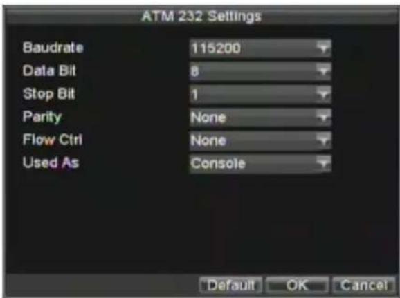
Figure 10. ATM 232 Settings Menu
Network Protocol
The Network Protocol is used for receiving the card No. and other information by adopting Server or Client mode to set up TCP connection with ATM.
- Enter ATM Setting menu, shown in Figure 11. Click Menu > Setting > ATM to enter ATM Settings menu.
- Click the ATM Enable checkbox to enable ATM function, and then select the connection type to Network Protocol.
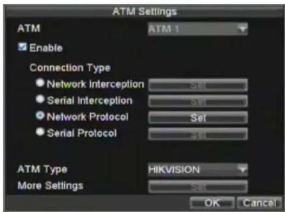
Figure 11. ATM Settings Menu
- Click the Set button to enter the DVR listening port settings menu.
- Set the DVR listening port, shown as Figure 12 below.
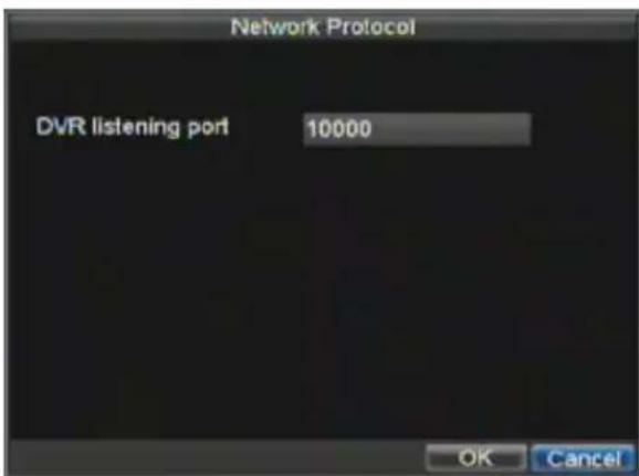
Figure 12. Network Protocol Menu
Network Protocol
The Serial Protocol is used for receiving the card No. and other information by directly receiving the data sent from the serial port connected.
- Enter ATM Setting menu. Click Menu > Setting >ATM to enter ATM Settings menu.
- Click the ATM Enable checkbox to enable ATM function, and then select the connection type to Serial Protocol.
- Click the Set button to enter the ATM232 settings menu.
- Configure ATM232 settings, shown as Figure 10, including baud rate, data bit, stop bit, parity, flow control, etc.
Note: The Serial Interception and Serial Protocol cannot be selected simultaneously.
CHAPTER 13
DVR Management
Configuring System Settings
Configuring General Settings
General settings such as the system language can be configured in the General Settings menu of your DVR.
To configure general settings:
- Click Menu > Settings > General to enter the General Settings menu, shown in Figure 1.

Figure 1. General Settings Menu
- Select the General tab.
- Configure general settings, including:
• Language: Default language used in DVR menus.
• CVBS Output Standard: Video output standard: NTSC and PAL.
• VGA Resolution: VGA output resolution.
• Time Zone: Time zone to use for DVR.
- Menu Date Format: Format for date.
• System Time: System time and date.
- Mouse Pointer Speed: Speed of mouse pointer.
- Enable Password: Enable/disable system password.
Note: If the video standard is different between the input and the output, you may notice flickering in Live Preview mode. After having modified the video standard, please reboot the device to validate the settings.
Configuring Advanced Settings
To configure more advanced settings:
- Click Menu > Settings > General to enter the General Settings menu, shown in Figure 1.
- Click the More Settings tab to enter the More Settings menu, shown in Figure 2.
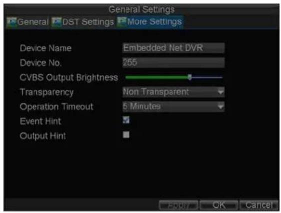
Figure 2. More Settings Menu
- Configure the following settings:
• Device Name: Name of the DVR used.
• Device No.: Device number of DVR.
• CVBS Output Brightness: Video output brightness.
• Transparency: Menu transparency.
- Operation Timeout: Set timeout time for menu inactivity. For example, if timeout time was set to 5 minutes, after 5 minutes of inactivity in the General Settings menu, you'll be returned to the Live Preview.
• Event Hint: Enable/disable event hint function.
- Output Hint: Enable/disable video output hint for main or aux video output.
Note: DS-8100AH (F) (L) I-ST does not provide the Output Hint function.
RS-232 Port Settings
To configure RS-232 devices to be used with the DVR:
- Click Menu > Setting > RS232 to enter the RS-232 Settings menu, shown in Figure3.
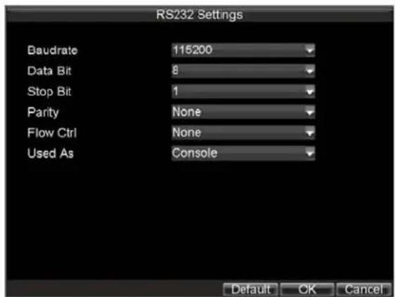
Figure 3. RS-232 Settings Menu
-
Configure RS-232 Settings.
-
The RS-232 port can be used in two ways:
- Parameter Control: Connect a PC to the DVR using the PC serial port. Device parameters can then be set using software such as HyperTerminal. The serial port parameters must be the same as the DVR's when connecting with the PC serial port.
- Transparent Channel: Connect a serial device directly to the DVR. The serial device will be controlled remotely by the PC through the network and the protocol of the serial device.
Managing User Accounts
By default settings, your DVR is configured with the user name of admin and the password of 12345. The Administrator has the authority to add, delete or configure the user parameters.
Adding a New User
To add a new user:
Click Menu > Settings > User to enter the User Settings menu, shown in Figure 4.
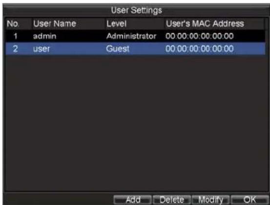
Figure 4. User Settings Menu
- Select the Add button to enter the Add User menu, shown in Figure 5. Note: Up to 31 users can be added.

Figure 5. Add User Menu
- Enter information for new user, including User Name, Password, Level and User's MAC.
- The Level is the user level and is separated into two tiers.
- Operator: By default, the Operator user level has the authority to configure two-way audio in network settings and all parameters in channel settings.
- Guest: By default, the Guest user can not configure network settings, but can configure the local playback as well as the remote playing in channel settings.
- If User's MAC is configured and enabled, the user may only access the DVR from that particular MAC address.
- Select the Permission button to enter the Permission Settings menu, shown in Figure 6.

Figure 6. Permission Settings Menu
-
Configure permission for local settings under Local Permission tab. The local settings include:
-
Local Log Search: Search and view logs of DVR locally.
- Local Configuration: Configure and restore parameters to factory defaults. Introduce settings to or export settings from DVR locally.
- Local Advanced Operation: HDD management (including the initialization and changing the properties of a disk). Ability to update system firmware as well as to stop the relay output locally.
-
Local Shutdown/Reboot: Shutdown or reboot the DVR locally.
-
Click on Network Permission tab to configure network permission settings, as shown in Figure 7. The network settings include:

Figure 7. Network Permission Settings Menu
- Remote Log Search: Remotely view logs that are saved on the DVR.
- Remote Configuration: Remotely configure parameters, restore parameters to factory defaults and import settings to as well as export settings from DVR.
- Remote Serial Port Control: Configure settings for RS232 and RS485 ports.
- Remote Video Output Control: Configure settings for video output.
- Two-way Audio: Ability to use two-way radio between the remote client and the DVR.
- Remote Alarm Control: Remote alert or control the relay output of the DVR. Alarm and exception settings must be configured properly to upload to host.
- Remote Advanced Operation: Remotely manage hard disk drives (initializing and setting properties for HDDs). Ability to remote update system firmware and stop of the relay output
-
Remote Shutdown/Reboot: Remotely shutdown or reboot the DVR.
-
Click on the Channel Permission tab to configure channel permission, as shown in Figure 8. The channel settings include:
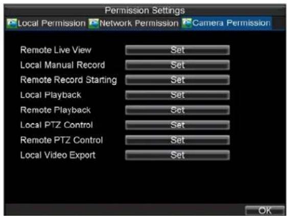
Figure 8. Camera Permission Settings Menu
- Remote Live View: Select and view live video over the network.
- Local Manual Record: Locally start and stop manual recording on any of the channels.
- Remote Record Starting: Remotely start and stop manual recording on any of the channels.
- Local Playback: Locally play recorded files that are on the DVR.
- Remote Playback: Remotely play and download recorded files that are on the DVR.
- Local PTZ Control: Locally control PTZ cameras.
- Remote PTZ Control: Remotely control PTZ cameras.
-
Local Video Export: Locally back up recorded files from any of the channels.
-
Click the OK button to save and exit menu.
Note: If you forget the password to your DVR, contact your supplier with the serial number of your DVR to obtain a secure code to reset your DVR.
Deleting a User
To delete a user from the DVR:
- Click Menu > Settings > User to enter the User Settings menu.
- Select user to delete.
- Click the Delete button to delete user.
- Click the OK button to exit menu.
Note: No deletion is allowed for the Administrator.
Modifying a User
To modify a user:
- Click Menu > Settings > User to enter the User Settings menu.
- Select user to modify.
- Click the Modify button to enter the Modify menu, shown in Figure 9.

Figure 9. Modify User Menu
- Edit user information.
- To modify user permissions, click on the privileges button. Permissions settings are defined in the Adding a New User section described above.
- Click the OK button to exit menu.
Managing System
Importing & Exporting Configuration
Configuration information from your DVR can be exported to a USB device and imported into another DVR. This will allow you to efficiently setup the same configuration on numerous DVRs.
To import or export DVR configuration:
- Click Menu > Maintenance > Configuration to enter the Import/Export Configuration menu, shown in Figure 10.
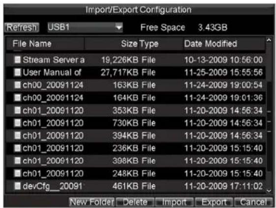
Figure 10. Import/Export Configuration Menu
- Click Export to export a configuration file to USB device. USB device must be connected at this point to the DVR.
- To import a configuration file, select the file from the USB device and click the Import button. After the import process is completed, the system will automatically reboot the DVR.
- Click Cancel to exit the current menu.
Updating System Firmware
The firmware on your DVR can be updated by using two methods. These methods include updating via an USB device or over the network via a FTP server.
To update via an USB device:
- Connect USB device to DVR. The firmware file must be located in the root directory of your USB device.
- Click Menu > Maintenance > Upgrade to enter the Firmware Update menu, shown in Figure 11.

Figure 11. Firmware Update Menu
- Select the Local Upgrade tab.
- Select the firmware on the USB device.
- Select Upgrade to begin the update process.
- The DVR will automatically reboot after the system firmware update is completed.
To update via a FTP server:
- Configure PC (running FTP server) and DVR to be in the same Local Area Network. Run the third-party FTP software on the PC and copy the firmware into the root directory of FTP.
- Enter the Firmware Update menu by clicking Menu > Maintenance > Upgrade.
- Select the FTP tab, shown in Figure 12.
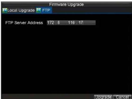
Figure 12. FTP Firmware Update
- Input the FTP server address.
- Select Upgrade to begin updating process.
- The DVR will automatically reboot after the system firmware update is completed.
Note: If the DVR is failed to update, please contact your system supplier for further assistance.
Restoring Default Settings
To restore default factory settings to your DVR:
- Click Menu > Maintenance > Default to enter the Default Settings menu, shown in Figure 13.
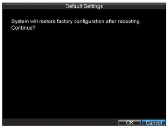
Figure 13. Default Settings Menu
- Select OK to restore factory defaults.
Note: Network information such as IP address, subnet mask and gateway will not be restored.
Viewing System Information
To view system information:
- Click Menu > Maintenance > Information to enter the Information menu, shown in Figure 14.

Figure 14. System Information
- Select OK to exit to the previous screen.
Viewing System Log
Many events of your DVR are logged into the system log.
To access the system logs and search for these events:
- Click Menu > Maintenance > Log Search to enter the Log Search menu, shown in Figure 15.
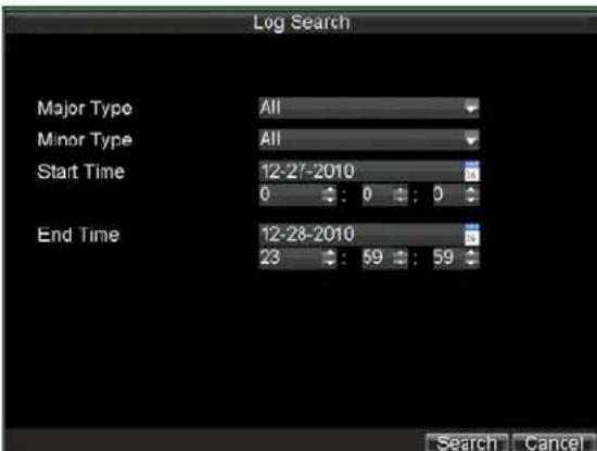
Figure 15. Log Search Menu
-
Set search parameters.
-
Click the Search button to start search. If logs matching the search conditions are found, it will be displayed in a list of search results as shown in Figure 16.

Figure 16. Log Search Results
-
To view more detailed information about a particular log entry, select the log and click the Details button.
-
If applicable, you may also view the associated video to the selected log entry by clicking the Play button.
-
Log files can also be exported onto a USB device. To export a log file, connect a USB device to the DVR, select the log file to export and click the Export button to enter the Log Search Export menu, shown below in Figure 17. Click the Export button to export log onto USB device. The exported file
will be named according to the time it was exported (e.g., 20100911143958logBack.txt).
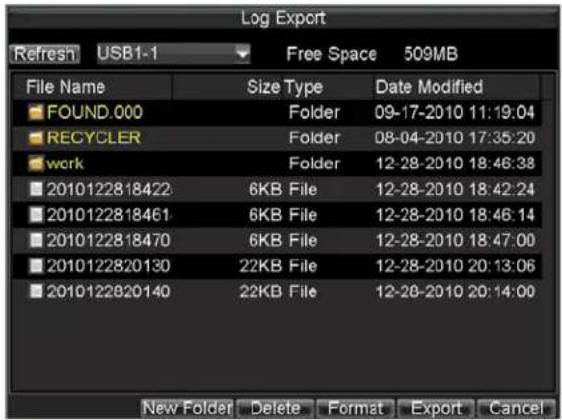
Figure 17. Log Search Export Menu
- Click Cancel to exit the current menu.
CHAPTER 14
Appendix
Glossary
- Dual Stream: Dual stream is a technology used to record high resolution video locally while transmitting a lower resolution stream over the network. The two streams are generated by the DVR, with the main stream having a maximum resolution of 4CIF and the sub-stream having a maximum resolution of CIF.
- DVR: Acronym for Digital Video Recorder. A DVR is device that is able to accept video signals from analog cameras, compress the signal and store it on its hard drives.
- HDD: Acronym for Hard Disk Drive. A storage medium which stores digitally encoded data on platters with magnetic surfaces.
- DHCP: Dynamic Host Configuration Protocol (DHCP) is a network application protocol used by devices (DHCP clients) to obtain configuration information for operation in an Internet Protocol network.
- HTTP: Acronym for Hypertext Transfer Protocol. A protocol to transfer hypertext request and information between servers and browsers over a network
- DDNS: Dynamic DNS is a method, protocol, or network service that provides the capability for a networked device, such as a router or computer system using the Internet Protocol Suite, to notify a domain name server to change, in real time (ad-hoc) the active DNS configuration of its configured hostnames, addresses or other information stored in DNS.
- NTP: Acronym for Network Time Protocol. A protocol designed to synchronize the clocks of computers over a network.
- NTSC: Acronym for National Television System Committee. NTSC is an analog television standard used in such countries as the United States and Japan. Each frame of an NTSC signal contains 525 scan lines at 60Hz.
- NVR: Acronym for Network Video Recorder. An NVR can be a PC-based or embedded system used for centralized management and storage for IP cameras, IP Domes and other DVRs.
- PAL: Acronym for Phase Alternating Line. PAL is also another video standard used in broadcast televisions systems in large parts of the world. PAL signal contains 625 scan lines at 50Hz .
- PTZ: Acronym for Pan, Tilt, Zoom. PTZ cameras are motor driven systems that allow the camera to pan left and right, tilt up and down and zoom in and out.
- USB: Acronym for Universal Serial Bus. USB is a plug-and-play serial bus standard to interface devices to a host computer.
FAQ
- Why does my DVR make a beeping sound after booting?
There are a few reasons for the warning beep your DVR makes after booting.
-
There is no HDD present in the DVR.
-
The HDD has not been initialized.
-
The HDD is defective.
If you wish to use your DVR without any HDDs, you may disable this warning beep in the Exception Settings menu (See Setting Exception).
- Why does the DVR seem unresponsive when operating with the IR remote control?
If your DVR seem unresponsive when using the IR remote and you have read through the section Using the IR Remote Control, please check:
- Check that the batteries are installed correctly in the remote, making sure that the polarities of the batteries are not reversed.
- Make sure the batteries are fresh and are not out of power.
- Make sure the remote has not been tampered with.
- Check around and make sure there are no fluorescent lamps in use.
• Why does the PTZ seem unresponsive?
If the PTZ seem unresponsive, please check:
- Check that the RS-485 cable is properly connected.
- Check that the dome decoder type is correct.
- Check that the dome decoder speed configuration is correct.
- Check that the dome decoder address bit configuration is correct.
- Check to make sure that the main board RS-485 interface is not broken.
- Why is there no video recorded after setting the motion detection?
If there are no recorded video after setting the motion detection, please check:
- Check that the recording schedule is setup correctly by following the steps listed in Scheduling a Recording.
- Check that the motion detection area is configured correctly (See Setting Up Motion Detection).
- Make sure that channels are being triggered for motion detection (See Setting Up Motion Detection).
- Why doesn't the DVR detect my USB export device for exporting recorded files?
There's a chance that the DVR and your USB device is not compatible. Please refer to our company's website to view a list of compatible devices.


- Preventive and Cautionary Tips
- TABLE OF CONTENTS
- CHAPTER 1....7
- Introduction....7
- CHAPTER 2....21
- Getting Started....21
- CHAPTER3....28
- Live Preview 28
- CHAPTER 4....33
- Record Settings 33
- CHAPTER 5....42
- Playback 42
- CHAPTER 6....50
- Backup 50
- CHAPTER 7....57
- Alarm Settings....57
- CHAPTER1
- Introduction
- Overview
- Product Features
- Compression
- Local Monitoring
- Hard Disk Management
- Recording
- Backup
- Alarm & Exception
- Others
- Network
- Development
- Product Application Diagram
- Operating Your DVR
- Using the Front Panel Controls
- DIRECTION/ENTER Buttons:
- DIRECTION/ENTER Buttons:
- Using the IR Remote Control
- Using the USB Mouse
- Left Button:
- Right Button:
- Scroll-Wheel:
- Using the Soft Keyboard
- Rear Panel
- CHAPTER2
- Getting Started
- Starting and Shutting Down Your DVR
- Rebooting and Locking Your DVR
- Using the Setup Wizard
- Setting Date & Time
- CHAPTER 3
- Live Preview
- Live Preview On-screen Display
- Live Preview Icons
- Live Preview Operation
- Mouse Operation in Live Preview
- Digital Zoom
- Configuring Live Preview Display
- Note:
- Setting Camera Order
- CHAPTER 4
- Record Settings
- Configuring Record Settings
- Before Record Settings
- Initializing Record Settings
- Scheduling a Recording
- Starting a Manual Recording
- Protecting Recorded Files
- Locking/Unlocking Recorded Files
- Setting HDD to Read-Only
- To set a HDD to read-only:
- Configuring Advanced HDD Settings
- Setting up HDD Redundancy
- CHAPTER5
- Playback
- Video Playback
- Playback Interface
- Playback by Video Search
- Playback by Event Search
- Playback by Card Number
- Playback by Preview Mode
- - By Using a Mouse:
- - By Using the Front Panel/Remote:
- - Multi-camera Playback
- Playback by System Log
- Playback Frame-by-Frame
- - By Using the Front Panel/Remote Control:
- CHAPTER 6
- Backing up Recorded Files
- Exporting Files
- Exporting Video Clips
- - By Using the Mouse:
- - By Using the Front Panel / Remote:
- Exporting Files via e-SATA
- Managing Backup Devices
- CHAPTER7
- Alarm Settings
- Configuring Alarms
- Motion Detection Alarm
- Enter Camera Setting:
- Sensor Alarm Settings
- Manual Alarm Triggering
- Video Loss Detection
- Video Tampering Detection
- Exception Settings
- To set exceptions:
- Understanding Exception Trigger Options
- CHAPTER8
- Network Settings
- Configuring Network Settings
- General Settings
- PPPOE Settings
- DDNS Settings
- NTP Server Settings
- Remote Alarm Host Settings
- Multicast Settings
- Server and HTTP Ports Settings
- E-mail Settings
- CHAPTER9
- PTZ Control
- PTZ Menu
- PTZ Settings
- Setting PTZ Presets, Patrols & Patterns
- Understanding PTZ Control
- Setting Presets
- Setting Patrols
- Setting Patterns
- CHAPTER10
- Camera Management
- OSD Settings
- Display Settings
- Privacy Mask Settings
- CHAPTER11
- HDD Management
- Managing HDDs
- Initializing HDDs
- Setting Network HDD
- Setting HDD Groups
- Setting HDD Status
- Setting HDD to Redundancy
- To set a HDD to redundancy:
- Checking HDD Status
- Configuring HDD Alarms
- CHAPTER 12
- ATM Settings
- Network Interception
- Serial Interception
- Network Protocol
- CHAPTER 13
- DVR Management
- Configuring System Settings
- Configuring General Settings
- Configuring Advanced Settings
- RS-232 Port Settings
- Managing User Accounts
- Adding a New User
- Deleting a User
- Modifying a User
- Managing System
- Importing & Exporting Configuration
- Updating System Firmware
- Restoring Default Settings
- Viewing System Information
- Viewing System Log
- CHAPTER 14
- Appendix
- Glossary
- FAQ
Brand : Syscom
Model : DS8116HCIST
Category : Voice recorder