
SRG - Gas detector Vemer - Free user manual and instructions
Find the device manual for free SRG Vemer in PDF.


| Product Type | Gas Detector |
| Brand | Vemer |
| Model | SRG |
| Dimensions (approx.) | 120 x 80 x 35 mm |
| Weight | 200 g |
| Power Supply | 2 x AA batteries (included) or 9V DC adapter |
| Detected Gases | Natural gas (methane), LPG (propane/butane) |
| Alarm Type | Audible (≥85 dB) and visual (red LED) |
| Sensor Life | 5 years |
| Operating Temperature | -10°C to +50°C |
| Humidity Range | 10% to 90% RH (non-condensing) |
| Mounting | Wall-mounted |
| Standards | EN 50194-1 |
| Test Button | Yes, for functional test |
| Low Battery Indicator | Yes, flashing LED and intermittent beep |
| End of Life Warning | Yes (after 5 years) |
| Maintenance | Clean with dry cloth; test monthly |
| Repairability | No user-serviceable parts; replace unit after sensor or battery failure |
| Warranty | 2 years |
Frequently Asked Questions - SRG Vemer
User questions about SRG Vemer
0 question about this device. Answer the ones you know or ask your own.
Ask a new question about this device
Download the instructions for your Gas detector in PDF format for free! Find your manual SRG - Vemer and take your electronic device back in hand. On this page are published all the documents necessary for the use of your device. SRG by Vemer.
USER MANUAL SRG Vemer
Read all the instructions carefully
■ The SRG is a control unit for the creation of gas detection systems in areas such as boiler rooms, workshops, warehouses, laboratories, etc. It is designed to work with probes such as CO Sensor, CH4 Sensor and LPG Sensor. It offers the possibility to control a solenoid valve or an auxiliary device (siren, flasher, etc.) using an alarm relay contained inside. The alarm or failure is displayed by LED.
SAFETY WARNINGS
To ensure correct installation, you must comply with the following
indications:
1) The device must be installed by a competent person
2) The device must be installed in a panel where, after installation, the terminals are no longer to occur.
can no longer be accessed 3) In the electrical system up the line from the energy meter there must be a
(b) In the electrical system up the line from the energy meter there must be a device to protect against overloads.
4) Connect the instrument following the diagrams shown in this sheet and in the
product marking
5) Before accessing the terminals, make sure the leads to connect to the
instrument are not electrically live
6) Do not power and connect the instrument if any part of it is damaged or
missing.
| Code | Model | Description |
| VE204400 | SRG | Gas detector with 1 connecting sensor |
| VE205100 | CH4 SENSOR | Methane detection sensor |
| VE206900 | LPG SENSOR | LPG sensor |
| VE207700 | CO SENSOR | Carbon monoxide sensor |
TECHNICAL CHARACTERISTICS
SRG control unit
• Power supply
- Voltage: 12V ac/dc ±10%
- Power consumption: \~ 160mA
- Connection: terminals of 2.5 Protection fuse 1A 5x20mm
- Input:
- Input: = 1 input for CH4 Sensor (methane). LPG Sensor (LPG) or CO Sensor (CO).
- Sensor connection: terminals of 2.5mm^2 C (common), S (signal), A (power supply)
- Max. length of connection: 50 m
– Cross-section of the leads: 1.5 mm ^2
• Output:
– Alarm: relay with exchange contact 8A/250V AC
– Failure: open collector 12V dc / 300mA max
- Output connection: terminals of 2.5 mm ^2
• Luminous signals: green LED: power supplied
yellow LED: failure red LEDs: gas alarm
• Reset/test button for alarm reset and probe test functions
• Degree of protection: IP20: IP40 when correctly installed in an electrical panel
• Degree of pollution: II
• Ambient temperature: 0 ÷ +50°
• Humidity: ≤90% R.H. without condensation
• Product for assembly on 6-module DIN rails
Sensors for SRG control units
• Power supply: from the control unit SRG
- Current input (at 6.5V): 40mA
- Connection: terminals of 2.5mm^2 C (common), S (signal), A (power supply)
• Models and calibration:
– Methane gas: CH4 Sensor, (default) 10% LIE of methane
– LPG: LPG Sensor, (default) 12% LIE of isobutene
- Carbon monoxide: CO Sensor, (default) 200ppm of carbon monoxide - Container in self-extinguishing plastic material
- Container: in self-extinguishing plastic material - Fastened to wall using screws and plastic plugs
• Protection: IP30
• Ambient temperature: 0 ÷ +50°C
• Humidity: ≦90% R.H. without condensation
INSTRUMENT DESCRIPTION
① Led power supply
② Led signaling failu
③ Led signaling gas alarm
④ Reset/Test button
⑤ Power supply terminals
⑥ Terminals for open collector failure ⑦ Terminals for alarm output relay
⑦ Terminals for alarm output relay ⑧ Terminals for gas sensor connection
⑥ Terminals for gas sensor connection ⑨ Set-up jumper
⑩ Protection fuse
INSTALLATION
Do not use the device in excess of the limits set forth in the technical data. The installer is responsible for correct, safe installation of the product. Use care during shipping, storage and handling.
1) Protection of the device.
To ensure the proper degree of protection of the unit, it is necessary to install the control
unit in an electrical panel constructed in accordance with current standards for the
workplace, and inside of which the power supply system can also be housed. The control
unit can be installed at the bottom of the panel or in DIN modular panels. The LPG, SO, and GJA form company designed to sell small units (electric)
The LPG, CO and CH4 Sensors are designed to be wall-mounted (vertically), using screws and plastic plugs. To proceed with installation, open the containers by unscrowing the
and plastic plugs. To proceed with installation, open the container by unscrewing the screw located on the ride. Make sure not to damage the sensor and not to touch the
screw located on the side. Make sure not to damage the sensor and not to touch the calibration devices.
2) Installation of the product
The correct installation of the probe is essential to proper operation of the system.
The correct installation of the proof is essential to proper operation of the system. Therefore, it must be installed:
– In areas with circulation of natural air;
– In areas that are not subject to dust or dirt that may render the sensor inoperative;
– Near jets of water, intake grilles, openings, etc;
– At an adequate distance from users of gas so as to prevent the system from intervening
improperly due to functional leakage.
Also, positioning depends on the type of gas to be detected, specifically:
- CH4 Sensor: Methane gas - at top, about 20-30 cm from the ceiling LPC Sensor: LPC - at bottom, about 20-30 cm from the floor
LFG Sensor: LFG - at bottom, about 20-30 cm from the flo CO Sensor: carbon monoxide - about 1.5 m from the floor
For new systems, the probe must be installed as late as possible, so that typical
construction site activities do not damage the detector.
3) Connections and use of the product.
Normal electrical cables can be used for connections. In any case, when installation is in places that are strongly exposed to electromagnetic disturbances, it is advisable to use shielded cables. The detection system must always be in operation. Therefore, the electrical power supply of the detector must not include switches or other devices that may accidentally shut it off. The power supply of the control unit must comply with the required values and the current in put of any device connect to the terminals of the relay must be less than or equal to the maximum capacity of the contacts. The average lifespan of the probes is 5 years from the date of installation. Therefore, at the end of that time they will need to be replaced.
Attention: make sure you check operation at least once a year, and in any case whenever there is an extended period of disuse or in the event of replacement. Any tampering may compromise correct operation of the system.
OPERATION
Once the device has been installed, you will need to select the operating logic using jumper E1. It can be either positive or negative. The control unit signals its operating status by means of LED's.

Depending on the logic selected using jumper E1, in a normal situation (no alarms), the LED's and the relay will be:
– positive logic: LED on, relay energized
– negative logic: LED off, relay de-energized
If negative operating logic is selected, the alarm relay may be controlled in permanent or impulsive mode, depending on the position of jumper E2:
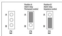
Once powered on, the control unit performs the following phases in sequence:
- Buzzer test (duration about 5 seconds) which causes sequential lighting of the LED's and a brief ringing of the buzzer.
- Pre-heating of the probe (which lasts about 1 minute), during which the detection system is not operational because this allows the probe to reach the correct operating temperature.
- Operational test (which lasts about 3 minutes) during which the power supply LED flashes with a frequency of 2Hz and all time settings are reset to zero to make it easier to check the probe. Press the Reset/Test for about one second to interrupt the operational test phase and check the probe.
- Gas alarm test, which occurs by placing the test spray can near the probe and releasing a small amount of gas. Do not direct the spray directly onto the sensor of the probe, as it may damage it irreparably. The control unit will signal the alarm in the following manner:
| Interface | Positive logic | Negative logic |
| Led (red) for probe alarm | Off | On |
| Alarm buzzer | Continuous sound Continuous sound | |
| Alarm relay | De-energized | Energized (permanently or in impulsive mode) |
Press the Reset/Test key for one second to silence the alarm (if the gas is no longer present) and end the test phase. To restart the test phase, press the corresponding button for about 6 seconds.
- Probe failure test, which is to be simulated simply by disconnecting the probe cable and checking the following signals:
| Interface | Positive logic | Negative logic |
| Led (yellow) for probe failure | Off | On |
| Alarm buzzer | Intermittent sound | Intermittent sound |
| Failure output | Off | On |
Once the test has been made, re-connect the probe and press the Reset/Test button to restore the control unit to normal operation.
Normal operation
During normal operation of the control unit, both the monitoring for gas alarm and the self-diagnosis for plant anomalies (probe) and systems anomalies (control unit) are active. In this phase and with no alarms or failures, the control unit status is as follows:
| Interface | Positive logic | Negative logic |
| Led (green) for power supply | On | On |
| Led (yellow) for failure | On | Off |
| Led (red) for gas alarm | On | Off |
| Alarm buzzer | No sound | No sound |
| Alarm relay | Energized | De-energized |
| Failure output | On | Off |
In presence of gas alarm or probe failure, the central unit goes into the same conditions described in the relatives test phase.
REFERENCE STANDARDS
Conformity to the EU direc
Conformity to the LO direct 2006/95/EC (Low Voltage)
89/336/EC modified by 92/31/ECC and 93/68/EEC (E.M.C.)
is declared with reference to the following harmonised standard:


Brand : Vemer
Model : SRG
Category : Gas detector