
VALV-34NA - Gas detector Vemer - Free user manual and instructions
Find the device manual for free VALV-34NA Vemer in PDF.


| Product Type | Gas Detector |
| Brand | Vemer |
| Model | VALV-34NA |
| Power Supply | 230 V AC, 50 Hz |
| Power Consumption | < 3 W |
| Sensor Type | Electrochemical or Semiconductor |
| Detected Gases | Natural Gas (Methane), Propane, Butane |
| Alarm Type | Audible (≥85 dB at 1 m) and Visual (LED) |
| Operating Temperature | -10°C to 50°C |
| Operating Humidity | 30% to 90% RH (non-condensing) |
| Dimensions | 80 x 80 x 35 mm |
| Weight | 100 g |
| Mounting | Wall mount (recommended height 1.5 m from floor) |
| Certification | EN 50194, CE |
| Warm-up Time | Approx. 3 minutes |
| Lifetime | 5 years from first power-up |
| Maintenance | Clean with a dry cloth; test weekly using test button |
| Safety Instructions | Do not ignore alarm; if alarm sounds, ventilate area immediately. Do not paint over the detector. |
| Spare Parts | No user-serviceable parts; replace unit after end of life. |
| Warranty | 2 years |
Frequently Asked Questions - VALV-34NA Vemer
User questions about VALV-34NA Vemer
0 question about this device. Answer the ones you know or ask your own.
Ask a new question about this device
Download the instructions for your Gas detector in PDF format for free! Find your manual VALV-34NA - Vemer and take your electronic device back in hand. On this page are published all the documents necessary for the use of your device. VALV-34NA by Vemer.
USER MANUAL VALV-34NA Vemer
natural_image
Two brass valve components with black and gold labels, one labeled 'MADAS' (no visible text or symbols on the main body)MADE IN ITALY
INDICE - INDEX - ÍNDICE
pag.
Italiano 3
English 14
Español.... 25
Disegni - Drawings - Diseños 36
Dimensioni (tabella 1) - Dimensions (table 1) - Dimensiones (tabla 1) ...... 39
Spare coils and connectors (table 2a - 2b - 2c)....
Bobinas y conectores de recambio (tabla 2a - 2b - 2c)....
This manual shows you how to safely install, operate and use the device.
The instructions for use ALWAYS need to be available in the facility where the device is installed.
ATTENTION: installation/wiring/maintenance need to be carried out by qualified staff (as explained in section 1.3) using appropriate personal protective equipment (PPE).
For any information pertaining to installation/wiring/maintenance or in any case problems that cannot be resolved with the use of the instructions, it is possible to contact the manufacturer from the address and phone numbers provided on the last page.
1.1 - DESCRIPTION
Normally open, manual reset solenoid valves for gas, suitable to shut-off gas and signal danger sent by gas detectors (methane, LPG, carbon monoxide and similar), safety thermostats, etc.
They can only be reset manually and only when they are not electrically powered.
They are fitted with a VPI (Visual Position Indicator) for visual indication of the valve plunger's position. When the valve is closed, the red band, which is usually hidden by the reset knob (1), is visible.
M16/RMOC N.A. versions are equipped with a push button (13) that allows to close manually the gas substituting the manual tap of the gas line allowing also to test at intervals the good working of the solenoid valve.
1.2 - KEY OF SYMBOLS

DANGER: In the event of inobservance, may be caused damages to tangible goods.

DANGER: In the event of inobservance, may be caused damages to tangible goods, to people and/or pets.

ATTENTION: Attention is drawn to the technical details intended for qualified staff.
1.3 - QUALIFIED STAFF
These are people who:
- Are familiar with product installation, assembly, start-up and maintenance;
- Know the regulations in force in the region or country pertaining to installation and safety;
- Are trained in first aid.

1.4 - USING NON-ORIGINAL SPARE PARTS
- To perform maintenance or change parts (ex. coil, connector, etc.) ONLY manufacturer-recommended parts can be used. Using different parts not only voids the product warranty, it could compromise correct device operation.
- The manufacturer is not liable for malfunctions caused by unauthorised tampering or use of non-original parts.

1.5 - IMPROPER USE
- The product must only be used for the purpose it was built for.
- It is not allowed to use different fluids than those expressly stated.
- The technical data set forth on the rating plate must not be exceeded whatsoever. The end user or installer is in charge of implementing proper systems to protect the device, which prevent exceeding the maximum pressure indicated on the plate.
- The manufacturer is not responsible for any damage caused by improper use of the device.
2.0 - TECHNICAL DATA
- Use : non-aggressive gases of the three families (dry gases)
• Ambient temperature : -20 ÷ +60 °C
• Power voltages (see table 2a - 2b - 2c) : 12 Vdc - 12 V/50 Hz - 24 Vdc - 24 V/50 Hz - 110 V/50-60 Hz - 230 V/50-60 Hz*
• Power supply tolerance : -15% ... +10%
• Electric wiring : cable gland M20x1.5
• Absorbed power : see table 2a - 2b - 2c
• Maximum operating pressure : 500 mbar - Closing time : < 1 s
• Protection rating : IP65 - Mechanical resistance : Group 2 (according to EN 13611)
- Rp threaded connections : (DN 15 - DN 20 - DN 25) according to EN 10226
- NPT threaded connections : on request
• In compliance with : EMC Directive 2014/30/EU - LVD Directive 2014/35/EU RoHS II Directive 2011/65/EU
* Only single-phase, the device does not work if powered with three-phase voltage.
2.1 - MODEL IDENTIFICATION
M16/RMO N.A. : Normally open manual reset solenoid valve, brass body
M16/RMOC N.A. : Normally open manual reset solenoid valve + closing manual push button, brass body
MBA/RMO N.A. : Normally open manual reset solenoid valve, brass body, low absorption
3.0 - COMMISSIONING THE DEVICE

3.1 - OPERATIONS PRIOR TO INSTALLATION
- It is necessary to close the gas upstream of the valve prior to installation;
- Make sure that the line pressure DOES NOT EXCEED the maximum pressure declared on the product label;
- Any protective caps (if any) must be removed prior to installation;
- Valve pipes and insides must be clear of any foreign bodies;
- Make sure that the pipe thread is not too long, to prevent damaging the body of the device when screwing it on;
- The safety regulations on handling loads in force in the country of installation must be complied with. If the device to be installed exceeds the weight allowed, suitable mechanical equipment and adequate slings must be used. Necessary precautions must be taken during the handling phases so as not to damage/ruin the external surface of the device.
- In accordance with EN 161 a suitable filter must be installed upstream of a gas closing safety device;
- With outdoor installation, it is advisable to provide a protective roof to prevent rain from damaging the electrical parts of the device.
- Prior to carrying out any electrical wiring operations, make sure that the main voltage matches the supply voltage indicated on the product label;
• Cut out power prior to proceeding with wiring;
- According to the plant geometry, check the risk of explosive mixture arising inside the piping;
- If the solenoid valve is installed near other devices or as part of an assembly, compatibility between the solenoid valve and this other device must be evaluated beforehand.
- Avoid installing the solenoid valve near surfaces that could be damaged by the coil temperature;
- Provide a protection against impacts or accidental contacts if the solenoid valve is accessible to unqualified personnel.


3.2 - INSTALLATION (see example in 3.4)
- Assemble the device by screwing it, with the due seals, onto the plant with pipes and/or fittings with the right threading for the connection being attached.
- Do not use the coil (3) as a lever to help you screw it on, only use the specific tool;
- The arrow, shown on the body (12) of the device, needs to be pointing towards the application;
- The device can also be installed vertically without prejudicing the correct operation. It cannot be put in upside down (with the reset knob (1) pointing downwards);
- During installation, avoid debris or metal residues from getting into the device;
- To guarantee mechanical tension-free assembly, we recommend using compensating joints, which also adjust to the pipe's thermal dilation;
- If the device is to be installed in a ramp, it is the installer's responsibility to provide suitable supports or correctly sized supports, to properly hold and secure the assembly. Never, for any reason whatsoever, leave the weight of the ramp only on the connections (flanged or threaded) of the individual devices;
- In any case, following installation, check the tightness of the plant;
- Wiring cannot have cables connected directly to the coil. ALWAYS and ONLY use the connector identified by the manufacturer;
- Before wiring the connector (5), unscrew and remove the central screw (4). Use the proper cable terminals (see figures next page). NOTE: Connector (5) wiring must be do ensuring a product rating of IP65;

- Wire the connector (5) with 3x0.75mm 2 cable for external ∅ 6.2 to 8.1 mm. The cable to be used must be in double sheath, suitable for outdoor use, with a minimum voltage of 500V and a temperature of at least 60 °C;


natural_image
Three-step diagram showing a circuit board being handled with a tool, then the circuit being connected to an electrical terminal (no text or symbols present)- Connect terminals 1 and 2 to the power supply and the earth cable to terminal ±
- Secure the connector (5) to the coil (3), tightening (recommended tightening torque 0.4N.m± 10% ) the clamping screw (4);
- The valve needs to be connected to earth either through the pipe or through other means (ex. cable jumpers).
3.3 - INSTALLATION IN PLACES WHERE THERE IS THE RISK OF EXPLOSION (DIRECTIVE 2014/34/EU)
The solenoid valve is not suitable for use in zones here there is the risk of explosion.
3.4 - GENERIC EXAMPLE OF AN INSTALLATION
- M16/RMO N.A. Manual reset solenoid valve
- SM jerk ON/OFF valve
- FM gas filter
- OPSO series MVB/1 MAX shut off valve
-
RG/2MC pressure regulator
-
MVSP/1 relief valve
- Pressure gauge and relative button
- Gas detector
- SM remote jerk ON/OFF valve lever control
- Expansion joint/anti-vibration mount


4.0 - MANUAL RESET
To reset the solenoid valve:
- Make sure the valve is NOT electrically powered;
- Close the flow downstream of the solenoid valve in order to balance the pressure between upstream and downstream when opening;
- Push the reset handgrip (1) and wait a few seconds for the pressure upstream and downstream of the valve to stabilise;
• After balancing the pressures, pull the reset knob (1) until it connects.
• To close maually the solenoid valve (only M16/RMOC N.A. versions), push the closing push button (13). - The red label under the manual reset (1), if visible, shows that the valve is closed.

5.0 - FIRST START-UP

- Before start-up make sure that all of the instructions on the rating plate, including the direction of flow, are observed;
- After having gradually pressurized the system, check the seal and operation of the solenoid valve, electrically powering / disconnecting the connector ONLY IF connected to the coil.
IMPORTANT NOTE: Do not use the connector as a switch to close the solenoid valve.
- Make sure the solenoid valve is closed by electrically connecting it.

5.1 - RECOMMENDED PERIODIC CHECKS
- Check tightness of the flanged/threaded connections on the system;
- Check tightness and operation of the solenoid valve;
It is the responsibility of the final user or installer to define the frequency of these checks based on the severity of the service conditions.

6.0 - MAINTENANCE
On completion of the operations described below, repeat the procedure indicated in paragraph 5. If the coil and/or connector need to be replaced (see fig. 1 and 2):

- Before performing any operation, make sure that the device is not electrically powered;
NOTE: if the coil (3) needs to be changed following an electrical failure, we recommend changing the connector (5) as well. The coil and/or connector replacement operations need to be carried out taking care to ensure the product's IP65 rating.

6.1 - REPLACING THE CONNECTOR
- Unscrew and remove the central screw (4), then remove the connector (5) from the coil (3);
- When you have taken out the existing internal electrical wiring, wire the new connector and secure it to the coil, as shown in 3.2

6.2 - REPLACING THE COIL
- Unscrew and remove the central screw (4), then remove the connector (5) from the coil (3);
- Loosen the screw (6) that locks the coil (3) and take it out of the armature assembly (2) along with the gaskets/discs;
- Place the new coil + gaskets + any discs inside the armature assembly (2) and secure with the relative screw or nut;
- Couple the connector to the coil and secure it as indicated in 3.2;
- If it is necessary to set up the wiring, proceed as described in 3.2.
NOTE: No maintenance operations need to be carried out inside the device.
7.0 - TRANSPORT, STORAGE AND DISPOSAL
- During transport the material needs to be handled with care, avoiding any impact or vibrations to the device;
• If the product has any surface treatments (ex. painting, cataphoresis, etc) it must not be damaged during transport; - The transport and storage temperatures must observe the values provided on the rating plate;
- If the device is not installed immediately after delivery it must be correctly placed in storage in a dry and clean place;
- In humid facilities, it is necessary to use driers or heating to avoid condensation.
- At the end of its service life, the product is to be disposed of separately from other waste (WEEE directive 2012/19/EU) and in compliance with the legislation in force in the country where this operation is performed.

8.0 - WARRANTY
The warranty conditions agreed with the manufacturer at the time of the supply apply.
For damage caused by:
- Improper use of the device;
- Failure to observe the requirements described herein;
- Failure to observe the regulations pertaining to installation;
- Tampering, modification and use of non-original spare parts;
are not covered by the rights of the warranty or compensation for damage.
The warranty also excludes maintenance work, other manufacturers's assembling units, making changes to the device and natural wear.
9.0 - RATING PLATE DATA
The plate data (see examples provided here) includes the following:
- Manufacturer's name/logo and address (possible distributor name/logo)
- Mod.: = name/model of the device followed by the diameter size
- P.max = Maximum pressure at which product operation is guaranteed
• IP.... = Protection rating - 230V.... = Power supply voltage, frequency (if Vac), followed by electrical absorption
- (-20... +60)ircC = Temperature range within which product operation is guaranteed
• year = Year of manufacture
- Lot = Product serial number (see explanation below)
• U1745 = Lot issued in year 2017 in the 45th week
• 25407 = progressive job order number for the indicated year
• 00001 = progressive number referred to the quantity of the lot
- = Disposal in accordance with WEEE directive 2012/19/EU

Via Moratello, 5/7 - 37045
Legnago (VR) - Italy www.madas.it
Mod: M16/RMO N.A. DN 15
P.max:500 mbar
IP65 - 230 V/50-60 Hz 7 VA
[-20...+60]°C
year: 2017 Lot: U1745 25407/00001

fig. 1
Rp DN 15 - Rp DN 20
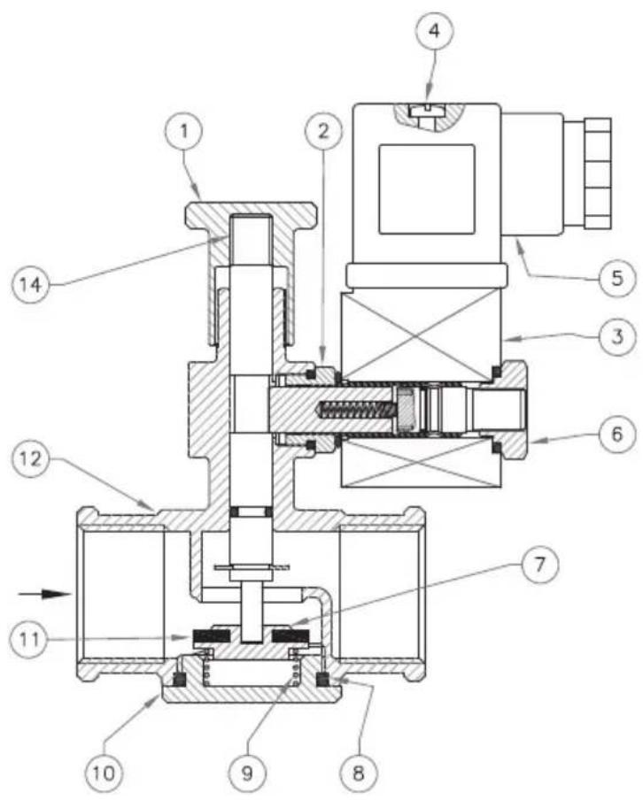
fig. 2
Rp DN 25
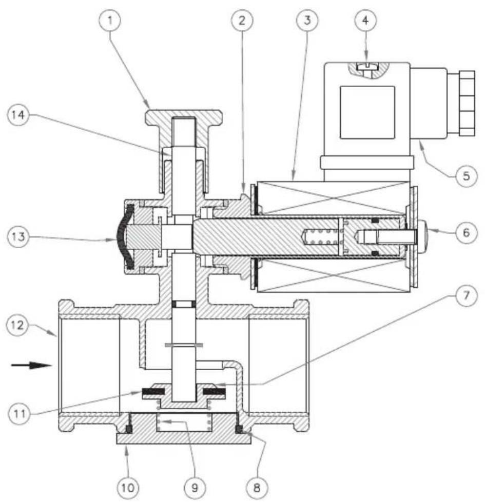
IT EN
fig. 1 e 2
- Reset knob
- Coil armature
- Electrical coil
- Connector clamping screw
- Electrical connector
- Coil clamping screw (or nut)
- Plunger
- Sealing O-Ring
- Closing spring
- Bottom sealing
- Sealing washer
- Valve body
- Closing manual push button (only on M16/RMOC N.A.)
- Central pin
ES
fig. 1 y 2
Attention: the combinations shown in the tables 2°, 2b and 2c are valid only for valves of the same model.
Example: M16/RMO... is interchangeable only with M16/RMO..., not with other models MBA/RMO...
Diagram calculated with P1 = 50 mbar
We reserve the right to any technical and construction changes.
Sede legale: Via V. Moratello, 5/6/7 - 37045 Z.A.I. Legnago (VR) Italy


- INDICE - INDEX - ÍNDICE
- ATTENTION: installation/wiring/maintenance need to be carried out by qualified staff (as explained in section 1.3) using appropriate personal protective equipment (PPE).
- - DESCRIPTION
- - KEY OF SYMBOLS
- - QUALIFIED STAFF
- - USING NON-ORIGINAL SPARE PARTS
- - IMPROPER USE
- - TECHNICAL DATA
- - MODEL IDENTIFICATION
- - COMMISSIONING THE DEVICE
- - OPERATIONS PRIOR TO INSTALLATION
- - INSTALLATION (see example in 3.4)
- - INSTALLATION IN PLACES WHERE THERE IS THE RISK OF EXPLOSION (DIRECTIVE 2014/34/EU)
- - GENERIC EXAMPLE OF AN INSTALLATION
- - MANUAL RESET
- - FIRST START-UP
- - RECOMMENDED PERIODIC CHECKS
- - MAINTENANCE
- - REPLACING THE CONNECTOR
- - REPLACING THE COIL
- - TRANSPORT, STORAGE AND DISPOSAL
- - WARRANTY
- For damage caused by:
- - RATING PLATE DATA
- IT EN
- fig. 1 e 2
- ES
- fig. 1 y 2
Brand : Vemer
Model : VALV-34NA
Category : Gas detector