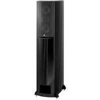
H-PAS AT-1 - Loudspeaker ATLANTIC - Free user manual and instructions
Find the device manual for free H-PAS AT-1 ATLANTIC in PDF.


| Product Type | 2-way M-T-M (Midrange-Tweeter-Midrange) loudspeaker |
| Model | H-PAS AT-1 |
| Brand | Atlantic Technology |
| Driver Configuration | Two 5 1/4" (135mm) GLH* woofers, one 1 1/8" (28mm) ferrofluid-cooled silk dome tweeter |
| Frequency Response | 29 Hz - 20 kHz (±3 dB) |
| Nominal Impedance | 6 Ω |
| Sensitivity | 89 dB |
| Recommended Amplifier Power | 20 - 200 Watts RMS |
| Crossover Frequency | 2 kHz |
| Crossover Type | Parallel, 2nd-order low-pass, 3rd-order high-pass |
| Enclosure Type | H-PAS™ (Hybrid Pressure Acceleration System) with CDFF™ internal bracing |
| Dimensions (W x H x D, with grilles) | 8 7/8" x 41" x 13 3/4" (227 x 1041 x 348 mm) |
| Dimensions (with feet) | Add 1" (25 mm) to height |
| Weight (each) | 54 lbs (25 kg) |
| Connection Options | Conventional single-wire or bi-amp (removable terminal straps) |
| High Frequency Energy Control | Adjustable tweeter level (+/0/-) for room compensation |
| Grille Attachment | Magnetic (neodymium) with keyed depressions |
| Feet Included | Cast aluminum with adjustable spikes and floor protectors |
| Accessories | Smoked glass top, wire management brackets |
| Warranty | Refer to manual for details; damage due to amplifier clipping not covered |
| Recommended Placement | 6-10 ft apart, about 1 ft from rear wall; toe-in optional |
Frequently Asked Questions - H-PAS AT-1 ATLANTIC
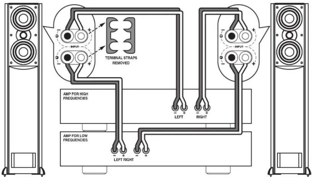
This configuration requires separate amplifiers for each section, increasing current delivery and reducing distortion.
User questions about H-PAS AT-1 ATLANTIC
0 question about this device. Answer the ones you know or ask your own.
Ask a new question about this device
Download the instructions for your Loudspeaker in PDF format for free! Find your manual H-PAS AT-1 - ATLANTIC and take your electronic device back in hand. On this page are published all the documents necessary for the use of your device. H-PAS AT-1 by ATLANTIC.
USER MANUAL H-PAS AT-1 ATLANTIC
High Performance Loudspeaker with H-PAST™ Technology
H-PAS

Atlantic TECHNOLOGY
Table of Contents
2 Introduction
3 Unpacking the Speakers
3 Attaching the Feet
3 Attaching the Grilles
3 Glass Tops
4 Placement
4 Using the AT-1 in a 2-channel Music System
4 Using the AT-1 in a Home Theater System
6 Connecting Your Speakers
6 Conventional Connection
6 Bi-amp Connection
6 Wire Management System
7 System Wiring
8 High Frequency Energy Control
9 Caring for Your Speakers
9 Specifications
For Future Reference
Record the serial number and date of purchase for each speaker here. The serial number is found on the speaker terminal panel on the back of the enclosure.
Serial Number
Serial Number
Date of Purchase
The contents of this manual are Copyright © 2010 by Atlantic Technology International, Corp., and may not be duplicated or reproduced by any means, whether physical, electronic or otherwise without prior written consent from Atlantic Technology International, Corp.
Atlantic Technology and the Atlantic Technology logo are registered trademarks of Atlantic Technology International, Corp.
Specifications are those in effect at the time of printing. Atlantic Technology International, Corp. reserves the right to change specifications or designs at any time without notice without obligation to modify existing units.
AT-1
High Performance Loudspeaker with H-PAS™ Technology
Thank you for choosing Atlantic Technology products. Your new speaker has been precision-crafted to give you years of enjoyable, trouble-free service. This manual covers the Atlantic Technology AT-1 speaker. It will show you how to incorporate these speakers into your present setup, as well as how to assemble a complete music or home theater system from them. The AT-1 can be used with all current and past sound formats including Stereo, all Dolby and DTS formats, DVD-Audio and SACD Audio.
Introduction
The Model AT-1 is a 2-way system of extraordinarily high performance intended for use in a top-quality music or home theater system. Its patent-pending H-PAS ™ bass technology enables the AT-1 to deliver powerful low bass performance (-3 dB @ 29 Hz) not previously achievable with comparably-sized drivers in similar-sized enclosures.
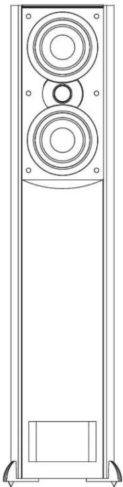
Each speaker contains two GLH (Graphite Loaded Homopolymer) 5 1/4" (135mm) woofers and an advanced 1 1/8" (28mm) ferrofluid-cooled, Low Resonance silk dome tweeter with an integral back chamber/heatsink. The drivers are configured in an M-T-M array (midrange-tweeter-midrange alignment). This vertical arrangement of drivers provides wide left-to-right coverage of sound while limiting the floor and ceiling reflections that can color the sound. These components are mounted in an acoustically inert MDF enclosure, with special proprietary internal bracing, called CDFF™ (Cross Design Free Flow). This bracing makes the enclosure extremely rigid, while perfectly maintaining the internal airflow that is critical to its performance.
IMPORTANT: Although it may seem like asking for driving directions, please take a few moments to read all of this booklet. It has many helpful tips and ideas on properly setting up and using your system. We promise that if you take the time to read and follow these tips you'll get better system performance and more enjoyment.
Instruction Manual
Unpacking the Speakers
Use care when unpacking the speakers. Since the grilles are packed off the speakers, be particularly careful of the driver elements as you unpack and move the speakers. Remember to keep the original boxes and packing material, in the unlikely event the speakers need servicing, or if you move.
Attaching the Feet
The cast aluminum feet with spikes are shipped unattached to the speaker. We recommend you attach the feet before proceeding to any other aspect of setup and installation.
Attach the feet to the bottom of the speaker cabinet as shown. The spikes can be adjusted to level the speaker. Circular metal discs are provided to protect hardwood floors.
Attaching the Grilles
The included metal grilles are held to the front of the enclosures with powerful neodymium magnets. There are depressions on the back of the grille the magnets fit into. Once the speakers are in their final position, remove the grille from its protective plastic bag and carefully position it over the magnets on the baffle.
Move them together slowly and when you get close enough, the magnets will draw the grille in and hold it tight. Be careful not to get your fingers caught between the grille and the cabinet.
Glass Tops
Decorative smoked glass tops are provided for the AT-1 to complete its elegant appearance. Attach the four self-adhesive rubber pads to the top of the cabinet as shown to prevent vibration and place the glass on top of the cabinet with the bevel towards the front. (See figure 2)
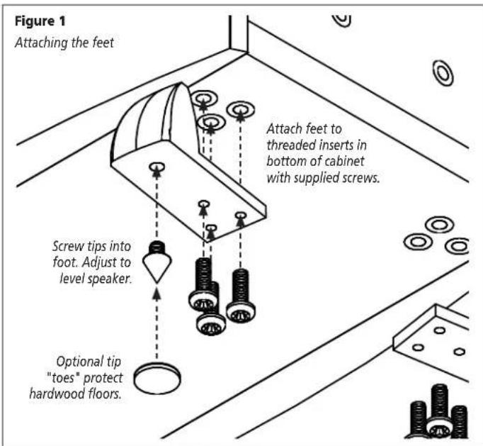
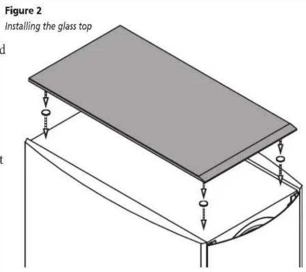
Figure 3
AT-1 High-performance loudspeaker
Placement
Speaker/room interactions have a huge impact on the sound of the system.
Moving the speakers just a little can make a dramatic difference in what you hear. Remember that the best acoustic placement of the speakers will vary from room to room. Use the following placement guidelines as a starting point. But also feel free to experiment. In fact, it may be beneficial to hook up the speakers with some extra wire and to simply drape the wire across the floor before installing the speakers permanently. This will allow you the opportunity to move the speakers around easily so you can find the be sonic and visual locations.
Using the AT-1 in a 2-channel Music System
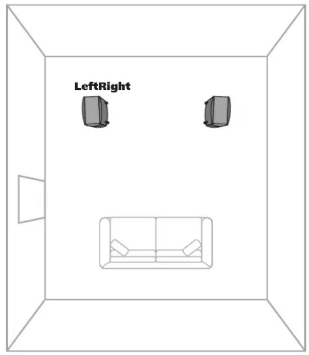
When using the AT-1 as a 2-channel music speaker (in a “stereo” system), place the speakers approximately 6-10 feet apart, so the distance between the speakers is roughly equal to the distance from the speakers to the listening position. (See figure 4) Begin with the AT-1 about 1 foot away from the wall behind it. Moving it closer to the wall will increase the apparent bass balance; pulling them farther away will yield a somewhat “leaner” bass balance. Experiment with the positioning to achieve the most satisfying balance in your room.
The AT-1 has very wide horizontal dispersion, due to its Low Resonance Tweeter (LRT ™ ) design and low woofer-to-tweeter crossover frequency. Therefore, it's not necessary to "toe in" the speakers as one ordinarily with conventional speakers. However, this is also a matter of individual preference, so again we encourage you to experiment and find the degree of sonic imaging precision that you find most pleasing.
Using the AT-1 in a Home Theater System
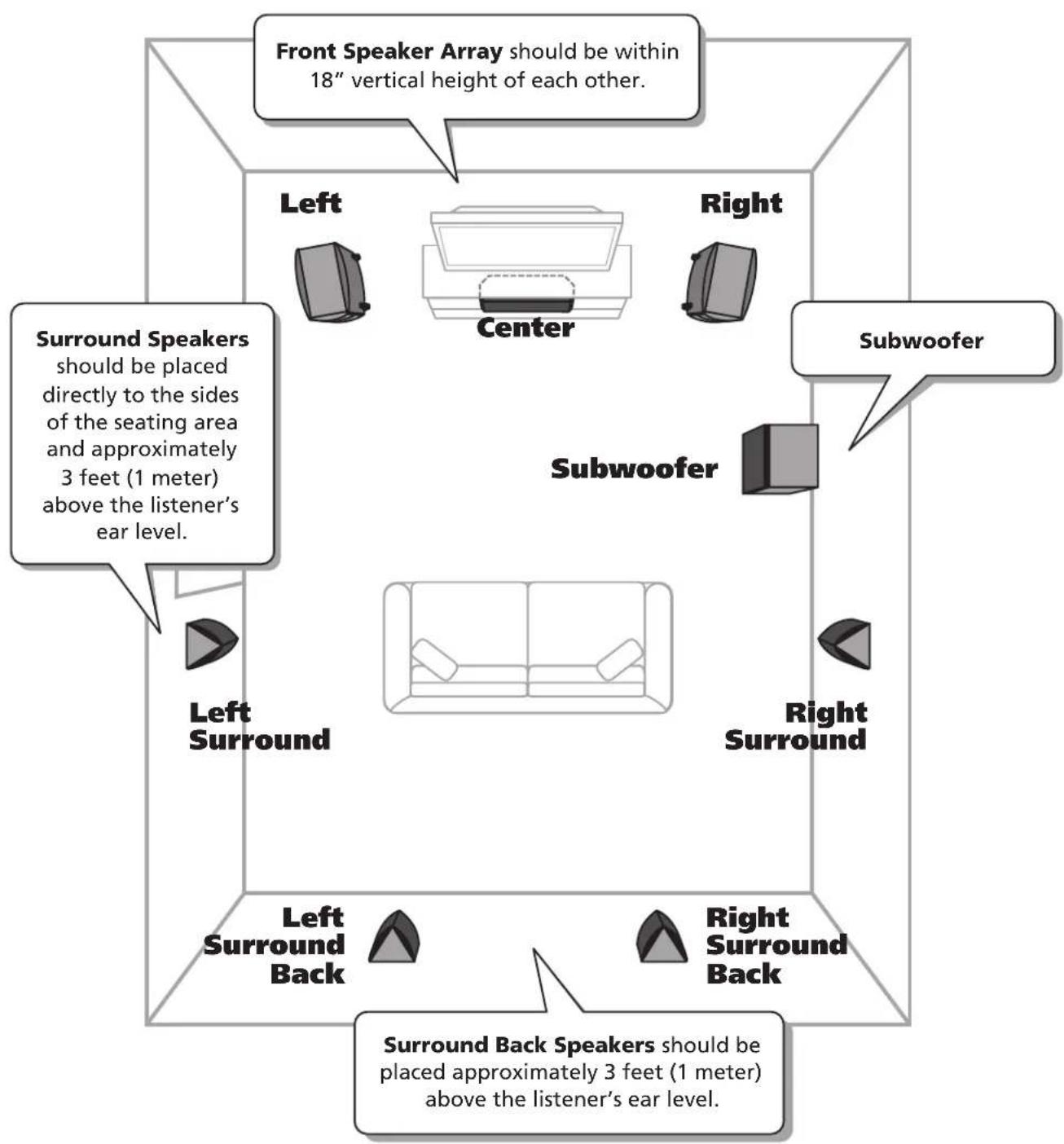
The AT-1 works extremely well as part of a home theater system. In such ya system, place the AT-1's on either side of the television. The left and right front speakers should be far enough apart (6 to 10 feet, 2-3 meters, is usually best) that you get a good stereo "image" when they are playing alone, but not so far apart that the sound seems to be disembodied from the TV, distracting you from the picture.
st Like all Atlantic Technology speakers, the AT-1 is tonally “voiced” to mix an match with our other models. The 4400 C or 6200e C both make excellent center channel speaker companions to the AT-1 LRs in a home theater system.
When using a center channel speaker in a home theater system, a wider separation of the left and right front speakers is usually possible than in a conventional 2-channel stereo system. Therefore, you may choose to toe in the AT-1 LR speakers slightly, aiming them towards the prime listening position. (See figure opposite)
IMPORTANT: Try to keep the AT-1's and Center channel speaker's tweeters at approximately the same height (within about 18" of each other) and aimed at ear level when seated. This is because we've designed the alignment of the drivers on the front panel to limit the vertical spread of the mid and high frequencies, thereby reducing the floor and ceiling reflections that can adversely affect sound quality. The AT-1's driver alignment provides an enhanced horizontal spread of the sound, making for a much better sound experience for a group of listeners and reducing the need to sit in a precise "sweet spot."
Figure 4
2-channel music configuration
Setting Bass Management
Even though the AT-1 delivers strong, deep bass response on its own, it is nonetheless desirable to use a powered subwoofer in a home theater system for the following reasons:
- The bass level of the powered subwoofer is controllable by the receiver's remote control. This is an extremely important feature to being able to "dial in" a satisfying bass level for your home theater system from your listening chair.
- When employing AT-1 speakers (along with a powered subwoofer) in a theater system, set your receiver's setup menu to "Subwoofer—Yes," and set your front speaker configuration to "Large" or "Full Range" (depending on how your receiver labels it). This will effectively give you three subwoofers in your home theater system, all residing in different physical locations throughout your listening room. Not only will having three subwoofers give you a higher level of undistorted, high-impact bass in your system, having them at different physical locations will randomize and smooth out the bass modes and standing waves in the room, resulting in a more uniform bass response with fewer room-caused 'hot spots' and 'cancellations.'
Follow your receiver and powered subwoofer manufacturers' recommendations for bass crossover setting and subwoofer placement. Generally, it's best to set the receiver's subwoofer crossover no higher than 80 Hz, in order to maintain non-localizability of the stand-alone powered sub.
Speaker Placement for Home Theater
Connecting Your Speakers
We recommend that you connect your system using high quality dual conductor stranded wire of 16 gauge or heavier, for lengths up to 25 feet (8m). Remember, the lower the gauge number, the heavier the wire. Use heavier gauge wire for longer runs. Please contact your audio/video dealer or installer for specific cable recommendations and further information regarding special circumstances.
The terminals themselves are designed to allow the use of very heavy speaker wire or connectors. Be sure to tighten them securely, but don't over-tighten them.
WARNING: To prevent risk of electrical shock or damage to your equipment, always switch off the amplifier or receiver when making any system connections.
Conventional Connection
Leave terminal straps in place. (See figure 6 opposite)
You can connect your speakers by using a variety of audio connectors such as pin connectors, spade lugs, etc., or you can:
- Remove 1/2 " (13mm) of insulation from each wire end.
- Twist the stranded wire together, keeping the two ends separate.
- Place the appropriate wire through the postholes in the connectors. These holes are revealed when you loosen the connector's capscrew.
- Screw down the capscrew tightly, but be careful not to over tighten it.
- Check the tightness of the capscrews 24 hours after hookup and occasionally after that, as they can loosen over time.
It's important to observe polarity while making speaker connections: red (+) terminals on the amplifier to red (+) on the speaker, black (−) on the amplifier to black (−) on the speaker. Look carefully at the wires you are using and note that one of the conductors of each pair will try identified by color, printing on the outer jacket, ridges on the outer jacket, or a thread intertwined with the wire strands. By convention, the marked wire is connected to the red (+) terminal.
WARNING: Before turning on the amplifier, be certain that no stray wire strands are touching across any terminals as this might damage your amplifier.
Finally, check the polarity of your speakers by listening to some stereo music with good bass content. If the sound seems “hollow”, unusually spread out, or seems to have weak bass, recheck your connections for proper polari and correct the out of phase connection, if necessary.
Bi-amp Connection
Remove terminal straps. (See figure 7 opposite)
Bi-amplification uses separate amplifiers for the high- and low-frequency sections of the speaker. Using separate amplifiers increases the current available to drive the speaker and decreases the audibility of amplifier-generated harmonic and intermodulation distortion, since the amplifiers' high- and low-frequency distortion products do not interact with each other the way they do in a single full-range amplifier. A speaker driven in bi-amplified mode will play louder and sound cleaner than the same speaker driven by a single full-range amplifier of equivalent combined wattage.
IMPORTANT: The power recommendation for these speaker systems assumes that you will not operate your amplifier/receiver in a way that produces distortion. Even rugged speakers like these can be damaged by an amplifier driven into audible distortion. The harsh amplifier distortion ("clipping") that occurs in this situation will eventually cause damage to the speaker system. This type of damage may be cumulative and can build up over time, as the amplifier is driven into overload again and again. Such damage is easily identifiable through examination of the damaged speaker's voice coil and is not covered by the warranty.
These speakers will play very loudly when provided with enough undistorted power to do so. If necessary, consult your dealer or Atlantic Technology for additional information.
Wire Management System
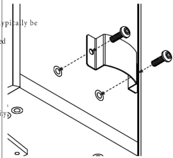
Attach the wire management guides to the speaker's rear panel as shown (see figure 5) with the included hardware. Run your speaker wire under the guides for a neat installation.
Figure 5
Installing the wire management brackets
Instruction Manual
System Wiring
Be sure to connect red (+) on the speaker to red (+) on the amplifier and black (−) on the speaker to black (−) on the amplifier.
Figure 6
Conventional Connection
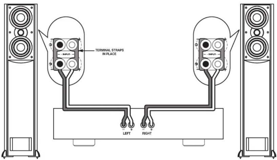
Figure 7
Bi-amp Connection
High Frequency Energy Control
This control changes the relative output level of the tweeter. It has been designed to help compensate for different room acoustics and personal listening preferences. The '0' position is the most "accurate" frequency response, but that does not mean that it is necessarily the "recommended" position.
The “+” and “-” positions adjust the tweeter’s output by very slight amounts over its entire operating range, from 2kHz to 20kHz. These positions change what’s known as the speaker’s “spectral balance” by altering the proportion of treble to bass over a wide frequency band.
Such adjustments, although relatively subtle, can make the AT-1 more suitable to different acoustic environments or tailor its sound more closely to one's tastes.
We encourage you to experiment with the different tweeter settings to find the one that sounds best in your room.

Caring for your Speakers
Clean your cabinets using a soft, lint-free cloth. If you wish, you can slightly moisten the cloth with plain water. Do not use any other cleaning agents or chemicals. Be careful not to get any water on the driver cones or tweeter domes. After carefully removing the grilles from the speakers by pulling them forward, gently clean the grilles with a quick pass from a vacuum cleaner with a brush attachment. This should remove any dust accumulation. Reattach them by lining up the magnet depressions in the back of the grilles with the magnets on the speaker baffle and slowly moving them closer until they connect with each other.
Avoid placing your speakers in direct sunlight or near a source of heat that may, over time, damage the finish.
IMPORTANT: SAVE YOUR BOXES! If you can do so, save the cartons, packing pieces, and plastic bags that came with your speakers. They will be useful in case you move or have to ship your loudspeakers for any reason. In any case, save all packing materials until you are certain that the systems have suffered no damage in shipment. If you find such damage, either visible or internal, contact your dealer immediately.
Instruction Manual
Specifications
| Model AT-1 | |
| Type H-PAS Hybrid Pressure Acceleration System,2-way M-T-M array | |
| Drivers Woofer (2) 5 1/4 " (135mm) long-excursion GLH* coneTweeter 1 1/8 " (28mm) low-resonance soft dome with 4mm oversizelong-throw surround and integral back chamber/heatsink | |
| Frequency Response 29-20kHz, +/-3dB | |
| Nominal Impedance 6 Ω | |
| Crossover Frequency 2kHz | |
| Crossover Type Parallel, 2nd-order LP, 3rd-order HP | |
| Sensitivity 89dB | |
| Recommended 20 – 200 Watts RMSAmplifier Power | |
| Dimensions w/ grilles (W x H x D) 8 7/8 x 41 x 13 3/4 "227 x 1041 x 348mmFeet add another 1" (25mm) to Height | |
| Weight (ea) 54 lbs (25 kg) ea. |
*Graphite Loaded Homopolymer
Specifications are those in effect at the time of printing. Atlantic Technology reserves the right to change specifications or appearance at any time without notice. All other trademarks are the property of their respective owners.
AT-1 High Performance Loudspeaker with H-PAS™ Technology
Instruction Manual

- TABLE OF CONTENTS
- FOR FUTURE REFERENCE
- AT-1
- HIGH PERFORMANCE LOUDSPEAKER WITH H-PAS™ TECHNOLOGY
- INTRODUCTION
- UNPACKING THE SPEAKERS
- ATTACHING THE FEET
- ATTACHING THE GRILLES
- GLASS TOPS
- PLACEMENT
- USING THE AT-1 IN A 2-CHANNEL MUSIC SYSTEM
- USING THE AT-1 IN A HOME THEATER SYSTEM
- SETTING BASS MANAGEMENT
- CONNECTING YOUR SPEAKERS
- CONVENTIONAL CONNECTION
- BI-AMP CONNECTION
- WIRE MANAGEMENT SYSTEM
- SYSTEM WIRING
- HIGH FREQUENCY ENERGY CONTROL
- CARING FOR YOUR SPEAKERS
Brand : ATLANTIC
Model : H-PAS AT-1
Category : Loudspeaker