
TLC-8.3 - Loudspeaker ATLANTIC - Free user manual and instructions
Find the device manual for free TLC-8.3 ATLANTIC in PDF.


| Product Type | In-ceiling loudspeaker |
| Model | Atlantic Technology TLC-8.3 |
| Driver Complement | 8" Polypropylene cone woofer with mica, rubber surround; Dual 1" soft dome tweeters, swivel 30°, ferro-fluid cooled, neodymium magnet |
| Crossover Frequency | 2500 Hz (18 dB/octave woofer, 12 dB/octave tweeter) |
| Frequency Response | 45 Hz – 22 kHz |
| Sensitivity | 89 dB |
| Impedance | 8 Ohms per channel |
| Recommended Amplifier Power | 10 – 150 watts per channel |
| Cut-Out Size | 9.625 inches (244 mm) diameter |
| Mounting Depth | 4.53 inches (115 mm) |
| Weight (Single Speaker) | 5.25 lbs (2.38 kg) |
| Grille | White steel, paintable, magnetically attached |
| Adjustable Tweeters | Yes, orbital socket allows 30° swivel |
| Bipole/Dipole Switch | Yes, for diffuse surround sound |
| Single-Point Stereo Capability | Yes, via jumper configuration |
| Pre-Construction Bracket | Optional (IC-NC-TLC-8) |
| Cut-Out Template Included | Yes |
| Wiring | Spring-loaded push terminals; two sets for single-point stereo |
| Minimum Mounting Surface Thickness | 10 mm (0.4 inches) |
| Compliance | Safety instructions: avoid water, heat, blockages; no user-serviceable parts |
Frequently Asked Questions - TLC-8.3 ATLANTIC
User questions about TLC-8.3 ATLANTIC
0 question about this device. Answer the ones you know or ask your own.
Ask a new question about this device
Download the instructions for your Loudspeaker in PDF format for free! Find your manual TLC-8.3 - ATLANTIC and take your electronic device back in hand. On this page are published all the documents necessary for the use of your device. TLC-8.3 by ATLANTIC.
USER MANUAL TLC-8.3 ATLANTIC
Trim-Look Ceiling Speakers
TLC-6.2
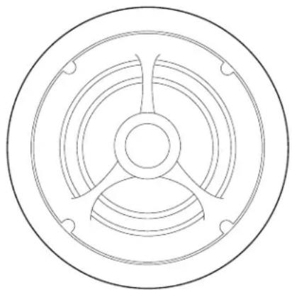
TLC-6.3

TLC-8.2

TLC-8.3

Table of Contents
2 Model TLC-6.2, -6.3, -8.2, -8.3
3 Important Safety Information
3 Features
3 Speaker Placement
3 2-Channel Audio Placement
4 Distributed Audio Placement
4 5.1 Channel Home Theater Placement
4 7.1 Channel Theater Placement
5 Home Theater (5.1 Channel) Layout [diagram]
6 Home Theater (7.1 Channel) Layout [diagram]
7 Using the 8.3 or 6.3 as a "Single Point Stereo" Speaker
7 Wire Gauge and Quality
8 Installation
8 Installing Your Loudspeakers During a New Construction/Renovation
8 Installing Your Loudspeakers in a Pre-Existing Construction
9 Fitting the Speaker into the Cut-Out Opening
10 Painting the Speakers and Grilles
10 Acoustic Adjustments
10 Single-Stereo (TLC-6.3 and 8.3) Models
10 Adjusting the Directionality of Your Speakers
11 Specifications
For Future Reference
Record your serial numbers and date of purchase here:
Model Number
Serial Number
Date of Purchase
The serial number is found on the back panel.
Copyright © 2011 Atlantic Technology International.
Specifications are those in effect at the time of printing. Atlantic Technology reserves the right to change specifications or designs at any time without notice.
Model TLC-6.2, -6.3, -8.2, -8.3
Trim-Look Ceiling Speakers
Thank you for your purchase and welcome to the family of Atlantic Technology owners. Please read the following installation and operation guidelines carefully to ensure enjoyment of your home audio system for years to come.
Although we recommend that Atlantic Technology flush-mount loudspeakers should be fitted by competent installation technicians, installation is also well within the means of a competent DIY enthusiast when performed with the aid of this instruction guide. You may also find it useful to visit our web site for the latest tips and techniques on installation.
Your Atlantic Technology flush-mount loudspeakers are designed to blend into your home interior while providing superior sound quality. At Atlantic Technology we continuously strive to improve our products and it is for this reason that we reserve the right to change product specifications without notice. The information concerning product specifications and instructions in this manual do not necessarily set forth all technical or other specifications of Atlantic Technology products.
Important Safety Information
- Do not use this or other electrical equipment near water or other liquids
• Clean only with a dry cloth - Do not block any ventilation openings. Install in accordance with all safety standards and regulations.
- Do not install near any heat sources such as stoves, radiators, heat registers, amplifiers or any other apparatus producing heat.
• Use attachments and accessories as indicated by the manufacturer. - No user-serviceable parts inside. Refer all servicing to qualified service personnel.
- Warning: To reduce the risk of fire or electrical shock, do not expose this apparatus to rain, moisture or other liquids.
- Warning: To prevent injury, this apparatus must be securely attached to the wall/ceiling in accordance with the installation instructions. No naked flame sources such as candles should be placed close to the product.
- Caution: Changes or modifications not expressly approved by Atlantic Technology could void the warranty.
Instruction Manual
Features
Polypropylene Cones: Polypropylene has physical properties that make it ideal for loudspeaker drivers and consequently is found in many of the world's finest loudspeakers. Its combination of stiffness and strength-to-weight ratio means that it results in a more precise and defined sound reproduction.
■ Soft-dome tweeters: Another feature often found in the world's finest loudspeakers. The low mass of treated cloth and its self-damping properties deliver more accurate sound with less distortion.
- Adjustable tweeters: The tweeters in your Atlantic Technology loudspeakers are mounted in an orbital socket and can be adjusted by gently pressing on their edge. This adjustment allows for directing the sound when the speaker may need to be offset from an ideal listening position due to aesthetic or physical reasons.
- Stable tweeter bridge mounting: The tweeters in our ceiling loudspeakers are mounted on an extremely stable bridge rather than on a central pole as found in many other designs. This mounting method is less prone to resonance and vibration than a central “pole” tweeter mount, resulting in cleaner sound, especially at high listening levels..
- Bipole/Dipole Switch (6.3 and 8.3 only): This switch allows these dual-tweeter speakers to operate as highly-effective diffuse surround speakers in a home-theater system when their tweeters are out of phase in the “Dipole” position.
- Cut-out template: Atlantic Technology loudspeakers come with a cut-out template to allow the installer to accurately measure the hole to be cut out in the wall or ceiling surface resulting in an easier installation process.
■ Pre-construction bracket: All Atlantic Technology loudspeakers have an optional plastic pre-construction bracket. Their use is optional, but can be very helpful to the installation process at the time the plasterboard is about to be attached to the wall/ceiling. Therefore they would be used only during more extensive renovations and not when retrofitting the loudspeakers into an existing surface.
■ Paintable Grilles: Your Atlantic Technology loudspeakers come with steel grilles pre-painted in white. These may be painted if required. Important: Please refer to the section later in this manual on painting grilles before you attempt any painting.
Speaker Placement
The pivoting tweeters in Atlantic Technology loudspeakers are able to compensate for unusual placements of the speakers themselves. However, the ideal positioning of the speakers should be at roughly equal distances from the intended listening area and along a common wall. This helps to ensure the best stereo effect.
Naturally, intended listening positions are rarely static and they may vary considerably within a room. In these circumstances, you can confidently compromise on the ideal location and use the pivoting tweeter to assist without impacting your listening pleasure.
2-Channel Audio Placement
In standard two channel audio systems, the ideal distance between the left and right channel speakers should be in the range of 6-10 feet (1.8-3.0m) apart. If the layout of the joists and light fittings permit, the speakers should be equidistant from the most commonly used listening position.
Stereo Sound Layout
![graph TD A["Left Speaker"] --> B["Listening Area"] C["Right Speaker"] --> B B --> D["To ensure the best stereo effect, place speakers along a common wall, roughly equal distances from the intended listening area."]](/content/2026/06/1147767/images/e6c2d50a30439bae1b8c170bef26c4facd4371955a6b7f4cbd2521baf5df49a8.jpg)
Atlantic Technology ceiling loudspeakers feature swivelling tweeters to aim sound directly at the listening area to compensate for offset mounting.
Distributed Audio Placement
Atlantic Technology loudspeakers possess extremely smooth and predictable off-axis frequency response. However, in some cases, where the room is large, you may wish to consider the use of two (or more) pairs of speakers in order to provide a wider and more even dispersion of sound. A more even distribution of sound in this way means that people within the room are more likely to be equidistant from the speakers so that there are less “hot” or “cold” spots of audio volume.
When connecting more than one pair of speakers to an amplifier it is vital to maintain a compatible impedance load between the amplifier and speakers. Your amplifier will specify an acceptable impedance range which it can handle and you must ensure you do not drop the total impedance below that specified minimum level or you may damage your amplifier. If in doubt you should consult a professional installer or contact Atlantic Technology directly before commencing installation.
As an example, a typical amplifier may specify an acceptable operational impedance range of 4 to 8 ohms. If you connect two pairs of Atlantic Technology 8-ohm loudspeakers in parallel, the impedance you will present to the amplifier is 4 ohms. This is within acceptable limits of most quality amplifiers. If you connect them in series, you will present 16 ohms resistance to the amplifier which will reduce the available power, but be a very “safe” load for the amplifier.
Generally, you should not connect two 4-ohm loudspeakers in parallel, because then the impedance will be 2 ohms and may damage your amplifier. If they are connected in series, the impedance will be 8 ohms and therefore within acceptable limits.
Please note that, much like attaching a trailer to the back of a car, attaching a second set of speakers to an amplifier puts an additional load on the amplifier (or engine). This makes it work harder for the same performance or it may simply not have the power to perform satisfactorily. You need to check the capability of your chosen amplifier before attempting multiple speaker connection.
5.1 Channel Home Theater Placement
When using the 6.3 or 8.3 speakers as side channel speakers in a 5.1 channel home theater environment, they should be located directly alongside the listening area to just slightly (1-2 ft.) behind it. If you are setting them to Dipole (see diagram below), the tweeter with the single leg of the bridge should face towards the front of the theater (see diagram on page 5).
7.1 Channel Home Theater Placement
When using the 6.3 or 8.3 speakers as side and back channel speakers in a 7.1 channel home theater environment, they should be located directly alongside the listening area to just slightly (1-2 ft.) behind it. If you are setting them to Dipole, the tweeter with the single leg of the bridge should face towards the front of the theater (see diagram on page 6). The back speakers should be behind the listening position, about 1-2 ft. away from the rear wall if possible.

Generally, the best results are when the .3 back speakers are set to Bipole, whether or not the .3 side speakers are set to Dipole.
You may use the 6.2 or 8.2 as either side or back surround speakers, with excellent results, in either a 5.1 or 7.1 home theater system. If you are mixing .3 and .2 surround speakers in a 7.1 system, it is advisable to use the .3's as side surrounds, set to
Dipole. Use the angle tweeter capability on the .2 speakers to aim the tweeter away from the listeners, towards the wall, to create a more non-localizable, diffuse surround effect.
Instruction Manual
Home Theater (5.1 Channel) Layout
![graph TD A["Left Front"] --> B["Center Right"] C["Left Surround"] --> D["Listening/Viewing Area"] E["Right Surround"] --> D F["Front"] --> D](/content/2026/06/1147767/images/009ddb21f8e596f3e26f9dc8cc7a91b4e0db674c47a665aced80ebd2826af0a4.jpg)
Home Theater (7.1 channel) Layout
![graph TD A["Left Front"] --> B["Center Right"] C["Left Surround"] --> D["Listening/Viewing Area"] E["Right Surround"] --> D F["Left Back"] --> G["If Using .3's set to "Bipole""] H["Right Back"] --> G B --> D D --> G style D fill:#f9f,stroke:#333 style G fill:#ccf,stroke:#333](/content/2026/06/1147767/images/8ad90cfab516adb02d13418e612774e57157dabd9027c88351688da6d0d37d49.jpg)
Instruction Manual
Using the 8.3 or 6.3 as a "Single Point Stereo" Speaker
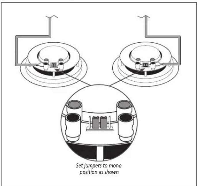
Your TLC 6.3/8.3 comes from the factory ready for conventional (mono) use. This means a single speaker will handle a single channel of information, such as what is required for surround channel use.

If you are going to use your .3 speaker for surround channel duties, leave the jumpers in the configuration shown to the left.
You may connect the speaker wires to either set of terminals.

If you want to use the TLC-6.3/8.3 as a “single-point stereo” speaker (where two channel’s worth of information is handled by the single unit), then move the jumpers to the position shown left.
Connect the speaker wires for one channel to one set of terminals, and the speaker wires for the other channel to the other set of terminals.
Wire Gauge and Quality
A good rule of thumb when installing speakers is to use 16-gauge wire for runs up to about 50 feet. Use 14-gauge wire for longer runs. 18-gauge is acceptable for short runs less than about 25 feet. Use speaker wire whose insulation meets local building codes. Consult a knowledgeable installer for more details.
Using two TLC-6.3 or TLC-8.3 speakers for stereo (conventional/surround use)
Using one TLC-6.3 or TLC-8.3 for single point stereo setup
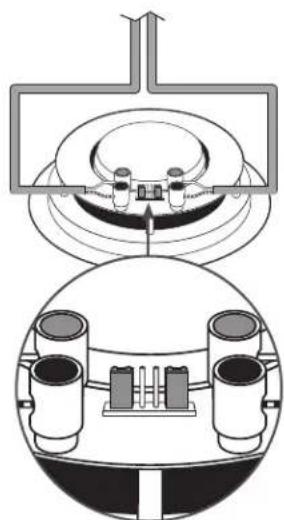
Set jumpers to stereo position as shown
Installation
Installing Your Loudspeakers During a New Construction/Renovation
If you are installing your flush-mount Atlantic Technology loudspeakers during a renovation or new construction, you will probably have the benefit of exposed joists, ceilings and stud walls. This makes the running of the speaker wire much more straightforward.
The mounting surfaces used should be at least 10mm thick to ensure safety and speaker stability.
Your Atlantic Technology loudspeakers have optional pre-construction brackets. These can be used to assist with installation. They can be nailed or stapled between the joists or studs in the planned speaker position with the flange of the speaker cutout facing out.
As the plasterboard is fitted you will find it easier to accurately cut out the necessary hole for your Atlantic Technology loudspeaker reducing installation time and debris when the speakers are being fitted.
installing TLC pre-construction bracket

Mounting TLC with pre-construction bracket

Installing Your Loudspeakers in a Pre-Existing Construction
If you are installing your flush-mount Atlantic Technology loudspeakers in existing construction, installation may be a little more challenging as you may have to fish cables to minimize any disruption to the decor of your home.
The first step in installing flush-mount loudspeakers in existing construction is to establish the location of the ceiling joists. You may be able to do this by lifting upstairs floorboards or using stud finding tools. If not, you may need to make pilot holes and a probe but recognize this may entail making cosmetic repairs afterwards.
Once a suitable location is identified, you will need to cut out the correct size opening in the surface of the plasterboard using the supplied cut-out template. You should make a pilot hole first and take care not to cut into pre-existing electrical cables or plumbing.
You will need to run speaker cable from the opening back to the amplifier (in the case of the Single-stereo model TLC-8.3 or 6.3, you will need two cables). Ensure you comply with any building codes that may apply in
Using the template to cut a hole

NOTE: When installing in an existing construction, take care not to cut through any existing wiring or plumbing.
Instruction Manual
your location.
Fitting the Speaker into the Cut-Out Opening
Before inserting the speaker into the opening in the wall/ceiling, attach the speaker cable(s) to the speaker, taking care to ensure the correct polarity of the speaker wires as this is critical to the correct operation of the speakers.
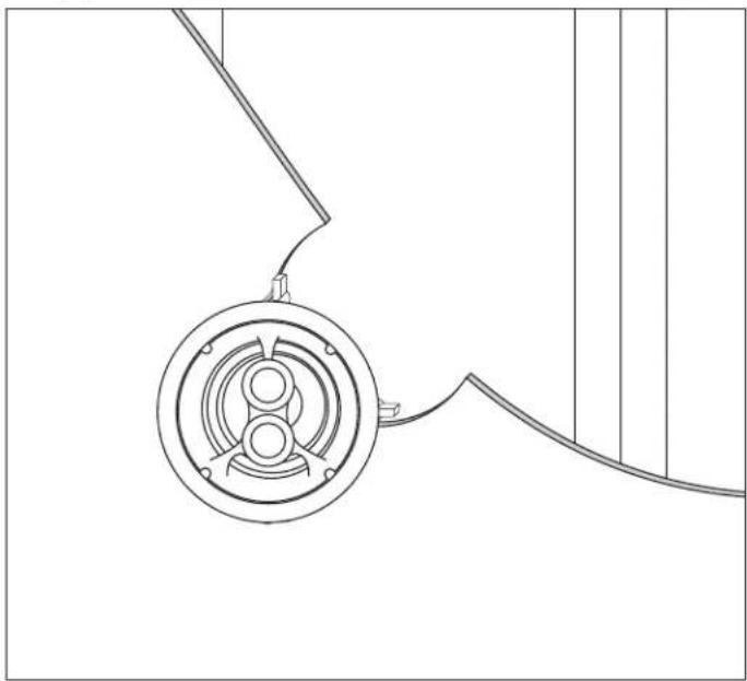
Insert the speaker housing into the opening and tighten the mounting screws to engage the "dog-leg" fasteners. Be careful to not over-tighten. The "dog-leg" fasteners will clamp the speaker frame and the mounting surface together.
To attach the speaker grille, position the grille over the speaker frame. Powerful magnets embedded in the frame will draw the grille towards the frame. Be sure the grille is centered properly over the frame and that it "snugs" down to the correct centered position.
Fitting speaker into cutout
Painting the Speakers and Grilles
Both the speaker frames and the grilles can be painted, if desired. We recommend doing this before installation. Always paint the grilles separately from the speaker itself. First, remove the white scrim cloth from behind the grille. The grilles should only be spray painted very lightly to avoid clogging the fine mesh of the grille and restricting the sound. Once the grille is dry, replace the scrim cloth by gently placing it behind the grille. No adhesive is necessary—gravity will keep it in place.
Only install the speakers and grilles once the paint has dried thoroughly.
Painting the grilles

Acoustic Adjustments
Single-Stereo (TLC-6.3 and 8.3) Models
These models use the same installation procedure as other models but need two speaker cables as they produce both left and right channel audio signals from one speaker housing. It is ideally suited to smaller rooms such as bathrooms. The crossover circuit board on the speaker features two sets of push-to-connect terminals and it is essential that the correct polarity of the connections to your amplifier is maintained. If the sound from the speaker lacks definition, it is likely the polarity is incorrect. It does not matter which speaker terminals are connected to the left or right channel on your amplifier, but the correct polarity is critical.
Adjusting the Directionality of Your Speakers
Note: Do not apply pressure to the tweeter dome itself. The pivoting tweeter can be used to direct sound towards or away from a listening area. To pivot the tweeter, apply light pressure to the plastic ring around the outside edge of the tweeter.
If your speakers are widely separated and the music fails to blend into a central image when the system is operated in stereo mode, you should orientate the tweeters toward the listening area.
If you are using your Atlantic Technology loudspeakers in a home theater environment, point the pivoting tweeter towards a wall or window to create a diffuse surround effect.
Should you have any questions or problems please feel free to contact us at 781-762-6300 or through our web site, www.atlantictechnology.com.
Instruction Manual
Specifications
| TLC-6.2 TLC-6.3 TLC-8.2 TLC-8.3 | ||||
| Woofer: | 6.5", PP cone with mica, rubber surround, 22 oz magnet, 1" voice coil, vented pole piece | 6.5", PP cone with mica, dual 1" voice coil, 22 oz magnet, vented pole piece | 8", PP cone with mica, rubber surround, 1.25" voice coil, 25 oz magnet, vented pole piece | 8", dual 1.25" voice coil, PP cone with mica, rubber surround, 25 oz magnet, vented pole piece |
| Tweeter: | 1" soft dome, swivel 30 degrees, ferro-fluid cooled, neodymium magnet, wide dispersion | Dual 19mm soft dome, ferro-fluid cooled, 30 degree swivel and pivot, neodymium magnet | 1" soft dome, swivel 30 degrees, ferro-fluid cooled, neodymium magnet, wide dispersion | Dual 1" soft dome, swivel 30 degrees, ferro-fluid cooled, neodymium magnet |
| Crossover: | 2700 Hz, 12dB woofer section, 12dB tweeter section | 2700 Hz, 12db per octave crossover for tweeters and woofer sections | 2500 Hz, 12dB woofer section, 12dB tweeter section | 2500 Hz, 18dB woofer section, 12dB tweeter section |
| Frequency Response: | 48Hz-22KHz 48Hz-22kHz 45Hz-22KHz 45Hz-22KHz | |||
| Sensitivity: | 88dB 88dB 89dB 89dB | |||
| Recommended amplifier power: | 10-125 watts 10-125 watts per channel 10-150 watts 10-150 watts per channel | |||
| Impedance: | 6 Ohms 8 Ohm per channel 6 Ohms 8 Ohm per channel | |||
| Cut-out size: | 8" (202mm) 8" (202mm) 9 | 5/8 " (244mm) 9 | 5/8 " (244mm) | |
| Mounting Depth: | 4.09" 3.82" 4.72" 4.53" | |||
| Weight (single speaker): | 3.5 lbs 3.6 lbs 5 lbs 5.25 lbs | |||
| Optional New Construction Bracket: | IC-NC-TLC-6 | IC-NC-TLC-6 | IC-NC-TLC-8 | IC-NC-TLC-8 |
Specifications are those in effect at the time of printing. Atlantic Technology reserves the right to change specifications or appearance at any time without notice.



- TABLE OF CONTENTS
- FOR FUTURE REFERENCE
- MODEL TLC-6.2, -6.3, -8.2, -8.3
- TRIM-LOOK CEILING SPEAKERS
- IMPORTANT SAFETY INFORMATION
- FEATURES
- SPEAKER PLACEMENT
- 2-CHANNEL AUDIO PLACEMENT
- DISTRIBUTED AUDIO PLACEMENT
- 5.1 CHANNEL HOME THEATER PLACEMENT
- 7.1 CHANNEL HOME THEATER PLACEMENT
- USING THE 8.3 OR 6.3 AS A "SINGLE POINT STEREO" SPEAKER
- WIRE GAUGE AND QUALITY
- INSTALLATION
- INSTALLING YOUR LOUDSPEAKERS DURING A NEW CONSTRUCTION/RENOVATION
- INSTALLING YOUR LOUDSPEAKERS IN A PRE-EXISTING CONSTRUCTION
- FITTING THE SPEAKER INTO THE CUT-OUT OPENING
- PAINTING THE SPEAKERS AND GRILLES
- ACOUSTIC ADJUSTMENTS
- SINGLE-STEREO (TLC-6.3 AND 8.3) MODELS
- ADJUSTING THE DIRECTIONALITY OF YOUR SPEAKERS
Brand : ATLANTIC
Model : TLC-8.3
Category : Loudspeaker