
IWTS-5 LCR - Loudspeaker ATLANTIC - Free user manual and instructions
Find the device manual for free IWTS-5 LCR ATLANTIC in PDF.


| Product Type | In-wall Loudspeaker |
| Model | IWTS-5 LCR |
| Brand | Atlantic |
| Woofer Size | 5.25 inches |
| Tweeter Size | 1 inch soft dome |
| Impedance | 8 ohms |
| Power Handling (RMS) | 50 watts |
| Power Handling (Peak) | 100 watts |
| Frequency Response | 80 Hz - 20 kHz |
| Sensitivity | 87 dB |
| Dimensions (H x W x D) | 7.1 x 4.0 x 3.5 inches |
| Cutout Dimensions (H x W) | 6.3 x 3.3 inches |
| Mounting Depth | 3.3 inches |
| Weight | 1.4 kg |
| Color | White (paintable grid) |
| Material | MDF baffle, ABS frame |
| Application | Front LCR or surround |
| Warranty | 5 years limited |
| Included Accessories | Cutout template, screws, manual |
Frequently Asked Questions - IWTS-5 LCR ATLANTIC
User questions about IWTS-5 LCR ATLANTIC
0 question about this device. Answer the ones you know or ask your own.
Ask a new question about this device
Download the instructions for your Loudspeaker in PDF format for free! Find your manual IWTS-5 LCR - ATLANTIC and take your electronic device back in hand. On this page are published all the documents necessary for the use of your device. IWTS-5 LCR by ATLANTIC.
USER MANUAL IWTS-5 LCR ATLANTIC
IWTS-5 LCR & IWTS-10 LCR
In-Wall Theater System Speakers
IWTS-5 LCR IWTS-10 LCR


Atlantic
TECHNOLOGY
Table of Contents
2 Model IWTS-5 LCR & IWTS-10 LCR
3 Important Considerations Before Installation
3 Recommended Wire Sizes
3 Location Considerations
3 Room Acoustics
3 Speaker Placement
3 Stereo Music Listening
4 Home Theater Systems
5 Mounting the IWTS Speakers
5 IWTS-10 LCR In-Wall Enclosure Recommendations
5 Ceiling Mounting
6 Installation of the IWTS in New Construction
6 Installation of the IWTS in Existing Construction
6 Removing and Installing the Grille
6 Cutting the Opening
6 Installing the Mounting Frame
6 Painting the Speaker Assembly
7 Speaker Connection and Assembly
7 Installing the Speaker Baffle Into the Frame
7 Front Panel Controls
7 HF (High Frequency) Level Control
7 IR Knockout
7 Specifications
For Future Reference
Record your serial numbers and date of purchase here:
Model Number
Serial Number
Date of Purchase
The serial number is found on the back panel.
Copyright © 2012 Atlantic Technology International.
Specifications are those in effect at the time of printing. Atlantic Technology reserves the right to change specifications or designs at any time without notice.
IWTS-5 LCR & IWTS-10 LCR
High Performance In-Wall Theater
System Speakers
Thank you for purchasing Atlantic Technology products. Our speaker systems have been designed to deliver exceptional sound and value. We hope you like what you hear from them, and are happy with your decision to buy them.
Please take a few moments to read these instructions. They're intended not only to tell you how to mount the speakers, but how to get the best performance from them.
Instruction Manual
Important Considerations Before Installation
Recommended Wire Sizes
The longer the wire run, the heavier the wire should be. Use the following recommendations as a guide for your installation. And if you're in doubt, remember that it never hurts to get the next heavier grade of wire. Also note that lower gauge numbers equal heavier wire sizes.
Wire Run Wire Gauge:
<15 ft. 16 ga.
15 to 30 ft. 14 ga.
30 to 50 ft. 12 ga.
Location Considerations
A major determinant of any speaker's sound quality is its location in the room. With in-wall speakers there are fewer placement options than with free-standing speakers, so giving some thought to location can really pay off. Our In-Wall Theater Systems have been designed to minimize the detrimental effects wall mounting can have on sound, so they sound better than conventional in-wall speakers.
Room Acoustics
Hard surfaces create lots of sound reflections in the room while soft surfaces tend to absorb sound. Note the speakers' location in terms of proximity to glass and other highly sound reflective or absorptive surfaces. A simple set of curtains or an area rug can make a major difference in sound quality and intelligibility by reducing excessive reflections.
The more similar the speaker's surroundings, the more consistent the sound will be. So placing one speaker directly adjacent to a glass wall, with the other speaker by an open archway, will make for two dramatically different sounding speakers.
Note that as bass frequencies reflect within the room, some locations may be bass heavy while other areas may be bass shy. With an external subwoofer, changing its placement within the room may reduce these effects. But when in-wall speakers are utilized full range, the only real option is to change the listening position, if you end up in a difficult bass area.
Speaker Placement
For all the following situations, it's recommended that you first place small box speakers in the proposed locations, just to get a good idea of how that location will sound. In-wall speakers are tough to move once they're installed!
Stereo Music Listening
For stereo music reproduction the speakers are best located at approximately ear level when seated, both on the same wall, facing the prime listening location. A separation of approximately six to eight feet between the left and right speakers is usually good. Ideally, the distance between the two speakers will be the same as the distance from the speakers to the listening position. The speakers and the listening position will then form an equilateral triangle. There is a benefit to mounting the speakers approximately the same distance from the side walls, so they both create the same reflective patterns.
Home Theater Systems
![graph TD A["Front Speaker Array should be placed as close to ear level as possible."] --> B["Left"] A --> C["Center"] A --> D["Right"] E["Subwoofer placement is dependent on room size and shape. Experiment to find a location that produces the smoothest response."] --> F["Subwoofer"] G["Optional Dipo…](/content/2026/07/1525729/images/364bc80fe3512da948d79eb9591a982f24ed87e88f32bc44a9b44925cfab9c55.jpg)
Today's home theater systems require you to place six or more speakers in your room. For the most convincing theater effects, speaker placement must be very carefully thought out. This is especially true with in-wall speakers, since their installation is permanent!
Left/Center/Right Locations The tweeter in the front three speakers should be at or just above ear height when seated, just as with stereo speakers. Try to keep the vertical position of the three front speakers within 18 inches of each other, as this will maintain smooth, believable left-center-right pans.
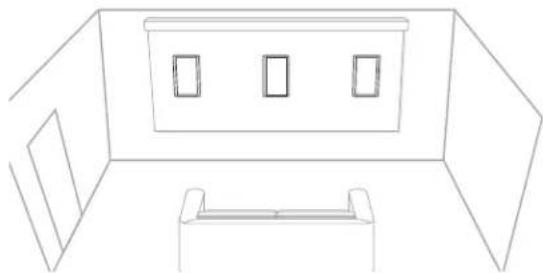
The spacing of the left-right speakers can be a little wider than with 2-channel stereo speakers, since in a theater system, the center channel speaker reproduces the on-screen effects and anchors the center image. Left-right spacing of about 8 to 10 feet usually works well.
Surround Speakers In order to achieve optimum performance we strongly recommend Atlantic Technology Dipole or TriVector™ surround speakers. If you are using our dedicated surround speakers please follow the placement recommendations included in their installation instructions.
Non-Dipole Surrounds The most realistic surround effects occur when the listener can't localize the actual location of the surround speaker. If you decide to use the In-Wall Theater System speakers as surround speakers, mount them above the listeners' ears, slightly behind the listening area either on the side or rear walls.
Instruction Manual
Mounting the IWTS Speakers
NOTE: We always recommend a professional be involved in the installation of IWTS speakers.
The IWTS speaker can be easily mounted in most any standard wall material, from 1/2 to 11/2 inches thick. Its rotating wall clamps (sometimes called "dog legs") firmly fix it to the wall surface after the proper cutout has been made. Here are some important precautions to take before mounting:
Keep the sides of the actual mounting hole at least 1/2 inch away from beams or studs to ensure that the clamps have adequate room to rotate. A stud or other obstruction that's too close will stop them from properly doing their job.
Wall cavity size will affect the bass and midrange performance of any in-wall speaker. The IWTS-5 LCR is designed to play optimally in a 0.5 to 1.0 cubic foot space (measured before wall insulation is inserted) and the IWTS-10 LCR in a 0.75 to 1.5 cubic foot space. Cubic dimensions can be determined by multiplying the length x width x height of the cavity. A larger cavity won't hurt, but a smaller one will negatively impact the bass and midrange response of the system.
Some of the sound from the speaker will transmit to the space on the other side of the wall cavity. If this is a major concern, you can build a box within the wall that provides the required cubic volume. Please note that there is very little room behind the drivers in a standard “2 x 4” wall cavity (there’s only 1/4 inch), so the back of any enclosure box must be made from thin material. Typically then, the back wall material of your enclosure will be roughly 1/8 to 1/4 inch thick.
For optimum sound install we recommend lining the cavity with fiberglass or polyfill, observing all the relevant precautions and instructions from the insulation manufacturer. If you have built a back box, you can use common fiberglass insulation or open cell foam rubber in the enclosure. Be sure to push the insulation back from the drivers to ensure that it doesn't get into the moving cone area.
IWTS-10 LCR In-Wall Enclosure Recommendations
Please use this information to construct an in-wall enclosure if you so desire. Doing so will generally improve the performance and increase the power handling of the system.
Be sure to line the cavity with insulation, being careful to avoid letting the insulation touch the backs of the woofer cones. It's also important to seal the joints of the enclosure with a high quality non-shrinking caulk.
Be careful to keep the wires from touching the chassis of the drivers or baffle in such a manner that the wire might vibrate and buzz. You may use nylon wire ties to keep the wires properly positioned. Such ties are available that are designed to screw directly to studs making them ideal for this purpose. As always, take care to wire the speakers properly, with the positive lead (normally marked with a red terminal or a “+” sign) from the amplifier connected to the positive terminal on the speakers and the negative (marked with a black terminal or a “-” sign) connected to its respective terminals.
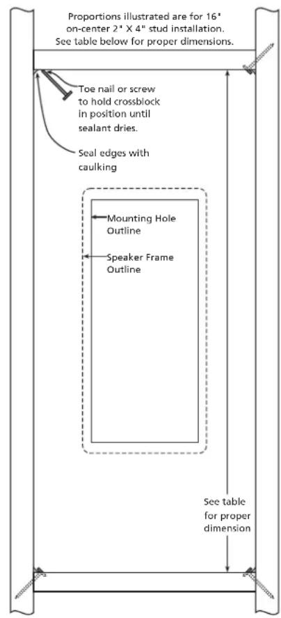
2 x 4 Construction 1ft 3 1.25ft 3 2 x 6 Construction 1ft 3 1.25ft 3
16" O.C.Studs 34" 42.5"
16" O.C.Studs 21.7" 27"
24" O.C. Studs 22" 27.5"
24" O.C. Studs 16"* 17.5"
* Minimum cut out height is 15.8". Placing the crossblock at 16" yields an internal volume of 1.15ft 3 .
Ceiling Mounting
It is especially important when mounting the speaker in a ceiling that you cover the back of the system with a fiberglass window screening (available at any home center or hardware store) to keep insulation and other foreign matter out of the assembly. You also should install safety wires from the rear of the assembly to a secure mounting place, like adjacent beams or the floor above, for added security. Should you be installing IWTS speakers in a suspended ceiling, it is imperative to install safety wires from the speaker to the support structure above, to ensure security under all conditions.
Installation of the IWTS in New Construction
Atlantic Technology offers optional Rough-in Frame Kits (IN-NC-5 and IN-NC-10) to ease installation in new construction. Instructions for its use are included with that kit.
Installation of the IWTS in Existing Construction
Removing and Installing the Grille
Remove the grille from the speaker using an awl or the point of a drywall screw in a grille opening near one of the grille corners. Slowly pry the grille out, being careful not to damage the speaker's frame or its finish.
To re-install the grille later, press it carefully into the appropriate opening in the frame assembly. Since it's designed to fit snugly, please take your time and use care when installing the grille.
For shipping, the speaker's baffle will be attached to the frame with two screws. Remove these screws to separate the baffle from the frame. Reserve the two screws for installation later.
Installing the Mounting Frame

The clamping mechanism allows the wall material to range from 1/2 to 11/2 inches (13 to 38 mm) in thickness. There must be a minimum depth behind the wall face of 35/8 ” (92 mm). As noted above, be sure to keep the edges of the cutout at least 1/2 inch (13 mm) away from any stud or obstruction, as the rotating clamps will not operate properly if you don’t. Insert the frame into the cutout and using a level or square carefully align it so it is level. Tighten the mounting screws, which will cause the attached clamps to rotate and position themselves properly behind the wall.
Continue to tighten until the frame is snug in the wall. You want the bezel to conform to the wallboard, and the frame not to rattle from the speaker's vibration, but be very careful not to overtighten the screws.
Cutting the Opening
![graph LR A["Document"] --> B["Page"] B --> C["Output"]](/content/2026/07/1525729/images/cc90c8d8a0cb648c183af40cdd6f7c8c581824b61757c49e5c16e45d1cc6a45d.jpg)
After determining the best location for the speaker as outlined above, use the enclosed template to cut the proper size hole.
IWTS-5 LCR 7 1/8" x 9 3/4" (181 x 248mm) IWTS-10 LCR 7" x 15 13/16" (178 x 402mm)
WARNING: Exercise extreme care before making any wall cuts to ensure that you will not cut through any wires, pipes, or other items that may be in the wall. You may sometimes, but not always, be able to determine the approximate location of wires and pipes by looking at the locations of nearby outlets and plumbing. But their location or absence is never an assurance that there is not something within the wall cavity.
Painting the Speaker Assembly

The white plastic frame and the metal grille may be left as is, or painted to match your décor. You can paint the frame before or after it is installed in the wall. Spray painting (using slightly thinned paint) is the best method to use for painting the grille. Remove scrim before painting. After painting the grille, use air pressure to "blow out" any grille holes that are filled in with paint. Replace scrim after paint is dry.
Instruction Manual
Speaker Connection and Assembly

Strip about 1/2 ” (13 mm) of insulation from the connecting wires. Connect them to the appropriate push terminal, being careful to observe polarity (positive to the red terminal, negative to the black terminal).
Installing the Speaker Baffle into the Frame
Once the frame is mounted in the wall, the speaker simply fits into the frame. Use the included screws (including two removed earlier) to attach the baffle to the mounting frame, but be very careful not to overtighten the screws.
Front Panel Controls
HF (High Frequency) Level Control
This control adjusts the relative level of high frequency output to compensate for varying room acoustics or placement behind a screen.
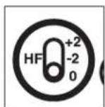
“+2” is for absorptive, acoustically “dead” rooms (or when the speaker is behind a movie screen). Use this position to increase the HF level and restore the proper sparkle and liveliness to the sound.
"0" is for rooms of average absorptive characteristics.
"-2" should be used in rooms that are highly reflective, with hard floors and exposed windows.
The setting of the HF control is mostly a matter of personal taste, so try it in all three positions and see which one is preferred.
for non-localizable surround use, or for room-filling background music ("whole house audio") use.
IR Knockout
There's a "knockout" plug in the front baffle. You can identify it by locating the Atlantic Technology wave logo which is molded into it. If you are using a multi-room control system, you can install a standard IR receiver in the knockout hole.
Specifications
IWTS-5 LCR IWTS-10 LCR
| Type | 2-way | M-T-M | |
| Optimum wall volume | 0.5 - 1 cu. ft. | 0.5 - 1.25 cu. ft. | |
| Drivers/Design woofers | 1 - 6 1⁄2" GLH* | 2 - 6 1⁄2" GLH* | |
| tweeter | 1 - 1" Silk dome | 1 - 1" Silk dome | |
| Frequency Response | 52 - 20kHz ± 3dB | 46 - 20kHz +/- 3dB | |
| Sensitivity | 87dB | 89dB | |
| Impedance 6 Ohms | 6 Ohms | ||
| Crossover Frequency | 3400Hz, 4th order Linkwitz-Riley | ||
| Amplifier Power | 25-125 Watts | 25-150 Watts | |
| Dimensions (grill frame) | 87/16" x 11" x 3/8" | 87/16" x 171⁄4" x 35/8" | |
| (W x H x D) | 215 x 280 x 86mm | 215 x 438 x 86mm | |
| Cutout Dimensions | 71⁄8" x 9 3⁄4" | 7" x 153/16" | |
| (W x H) | 181 x 248mm | 178 x 402mm | |
| Net Weight | 6.3lbs; 2.8kg each | 7.5lbs; 3.4kg each | |
| New Construction Kit | IN-NC-5 | IN-NC-10 | |
*Graphite Loaded Homopolymer
Specifications are those in effect at the time of printing. Atlantic Technology reserves the right to change specifications or appearance at any time without notice.
Should you have any questions or problems please feel free to contact us at 781-762-6300 or through our web site, www.atlantictechnology.com.



- TABLE OF CONTENTS
- FOR FUTURE REFERENCE
- IWTS-5 LCR & IWTS-10 LCR
- HIGH PERFORMANCE IN-WALL THEATER
- SYSTEM SPEAKERS
- IMPORTANT CONSIDERATIONS BEFORE INSTALLATION
- RECOMMENDED WIRE SIZES
- LOCATION CONSIDERATIONS
- ROOM ACOUSTICS
- SPEAKER PLACEMENT
- STEREO MUSIC LISTENING
- MOUNTING THE IWTS SPEAKERS
- IWTS-10 LCR IN-WALL ENCLOSURE RECOMMENDATIONS
- CEILING MOUNTING
- INSTALLATION OF THE IWTS IN NEW CONSTRUCTION
- INSTALLATION OF THE IWTS IN EXISTING CONSTRUCTION
- REMOVING AND INSTALLING THE GRILLE
- INSTALLING THE MOUNTING FRAME
- INSTALLING THE SPEAKER BAFFLE INTO THE FRAME
- FRONT PANEL CONTROLS
- HF (HIGH FREQUENCY) LEVEL CONTROL
- IR KNOCKOUT
Brand : ATLANTIC
Model : IWTS-5 LCR
Category : Loudspeaker