PD-55 - Screen AG Neovo - Free user manual and instructions
Find the device manual for free PD-55 AG Neovo in PDF.


| Product Type | LCD Flat Panel Display |
| Brand | AG Neovo |
| Model | PD-55 |
| Screen Size | 55 inches (139.7 cm) |
| Native Resolution | 1920 x 1080 (Full HD) |
| Aspect Ratio | 16:9 |
| Brightness (Typical) | 500 cd/m² |
| Contrast Ratio | 4000:1 (Dynamic) |
| Response Time | 8 ms |
| Viewing Angle (H/V) | 178°/178° |
| Input Connectors | VGA, DVI-D, HDMI, DisplayPort |
| Built-in Speakers | Yes, 10W x 2 |
| VESA Mount Compatibility | 400 x 400 mm |
| Power Consumption (Typical) | 150 W |
| Power Supply | AC 100-240V, 50/60Hz |
| Dimensions (W x H x D) | 1275 x 745 x 100 mm (without stand) |
| Weight (Net) | 28 kg (without stand) |
| Operation Temperature | 0°C to 40°C |
| Storage Temperature | -20°C to 60°C |
| Cleaning Instructions | Use a soft, dry cloth; avoid harsh chemicals |
| Spare Parts Availability | Contact AG Neovo support for replacement parts |
Frequently Asked Questions - PD-55 AG Neovo
User questions about PD-55 AG Neovo
0 question about this device. Answer the ones you know or ask your own.
Ask a new question about this device
Download the instructions for your Screen in PDF format for free! Find your manual PD-55 - AG Neovo and take your electronic device back in hand. On this page are published all the documents necessary for the use of your device. PD-55 by AG Neovo.
USER MANUAL PD-55 AG Neovo
SAFETY INFORMATION .... 1
Federal Communications Commission (FCC) Notice (U.S. Only)....1
CE Declaration of Conformity....2
Polish Center for Testing and Certification Notice 3
Electric, Magnetic and Electromagnetic Fields ("EMF") 3
Information for U.K. only....4
North Europe (Nordic Countries) Information 5
End-of-Life Disposal 6
Waste Electrical and Electronie Equipment-WEEE 6
Turkey RoHS 7
Ukraine RoHS 7
PRECAUTIONS 8
Cautions When Setting Up 8
Cautions When Using....9
Cleaning and Maintenance....9
Notice for the LCD Display 10
CHAPTER 1: PRODUCT DESCRIPTION.... 11
1.1 Package Contents 11
1.2 Preparing for the Installation 12
1.3 Installing and Removing Table Stands (optional) 12
1.4 Wall Mounting Installation.... 13
1.4.1 VESA Grid 14
1.4.2 Ventilation Requirements for Enclosure Locating.... 14
1.5 Mounting in Portrait Position 15
1.6 Using the Remote Sensor and Power Status Indicator 15
1.7 LCD Display Overview 16
1.7.1 Control Panel.... 16
1.7.2 Input/Output Terminals 18
1.8 Remote Control 21
1.8.1 General Functions 21
1.8.2 ID Remote Control....22
1.8.3 Inserting the Batteries in the Remote Control 23
1.8.4 Handling the Remote Control 23
1.8.5 Operating Range of the Remote Control 23
CHAPTER 2: MAKING CONNECTIONS....24
2.1 Connecting the Power 24
2.2 Connecting a Computer 25
2.2.1 Using VGA Input 25
2.2.2 Using DVI Input 25
2.2.3 Using HDMI Input 26
2.2.4 Using DisplayPort Input....26
TABLE OF CONTENTS
2.3 Connecting External Equipment (DVD / DVD-B).... 27
2.3.1 Using COMPONENT Video Input 27
2.3.2 Using Video Source Input.... 27
2.3.3 Using HDMI Video Input 28
2.4 Connecting Audio Equipment 28
2.4.1 Connecting External Speakers 28
2.4.2 Connecting an External Audio Device 29
2.5 Connecting Multiple Displays in a Daisy-chain Configuration 30
2.5.1 Display Control Connection 30
2.5.2 Digital Video Connection 30
2.5.3 Analog Video Connection 32
2.6 IR Connection....32
2.7 IR Pass-Through Connection 33
2.8 Connecting to Wired Network....33
CHAPTER 3: USING THE LCD DISPLAY....34
3.1 Turning on the Power 34
3.2 Selecting the Input Source Signal 34
3.3 Adjusting the Volume 35
3.4 Changing the Picture Format 35
3.5 Choosing Your Preferred Picture Settings.... 36
3.6 Choosing Your Preferred Sound Settings.... 36
3.7 Playing Multimedia Files via Local Area Network 37
3.7.1 Set Up the Network 37
3.7.2 How to Use DLNA-DMP 38
3.7.3 How to Use DLNA-DMR from PC.... 39
3.8 Playing Multimedia Files from USB Device 40
3.9 Play Options 42
3.9.1 Playing Music Files 42
3.9.2 Playing Movie Files 43
3.9.3 Playing Photo Files 44
CHAPTER 4: ON SCREEN DISPLAY MENU....45
4.1 Using the OSD Menu 45
4.2 OSD Menu Tree 47
CHAPTER 5: ADJUSTING THE LCD DISPLAY 49
5.1 Picture Settings 49
5.2 Sound Settings....53
5.3 Tiling Settings 54
5.4 General Settings.... 56
5.5 Network Settings 64
TABLE OF CONTENTS
CHAPTER 6: APPENDIX....66
6.1 Warning Messages....66
6.2 USB Device Compatibility 67
6.3 Supported Resolution....70
6.4 Cleaning 71
6.5 Troubleshooting....73
6.6 Transporting the LCD Display 74
CHAPTER 7: SPECIFICATIONS....75
7.1 Display Specifications 75
7.2 Display Dimensions....77
7.2.1 PD-42 Dimensions 77
7.2.2 PD-49 Dimensions 77
7.2.3 PD-55 Dimensions 78
Federal Communications Commission (FCC) Notice (U.S. Only)

This equipment has been tested and found to comply with the limits for a Class B digital device, pursuant to part 15 of the FCC Rules. These limits are designed to provide reasonable protection against harmful interference in a residential installation. This equipment generates, uses and can radiate radio frequency energy and, if not installed and used in accordance with the instructions, may cause harmful interference to radio communications. However, there is no guarantee that interference will not occur in a particular installation. If this equipment does cause harmful interference to radio or television reception, which can be determined by turning the equipment off and on, the user is encouraged to try to correct the interference by one or more of the following measures:
- Reorient or relocate the receiving antenna.
- Increase the separation between the equipment and receiver.
- Connect the equipment into an outlet on a circuit different from that to which the receiver is connected.
- Consult the dealer or an experienced radio/TV technician for help.

Changes or modifications not expressly approved by the party responsible for compliance could void the user's authority to operate the equipment.
Use only an RF shielded cable that was supplied with the display when connecting this display to a computer device.
To prevent damage which may result in fire or shock hazard, do not expose this appliance to rain or excessive moisture.
THIS CLASS A DIGITAL APPARATUS MEETS ALL REQUIREMENTS OF THE CANADIAN INTERFERENCE-CAUSING EQUIPMENT REGULATIONS.

This device complies with Part 15 of the FCC Rules. Operation is subject to the following two conditions: (1) this device may not cause harmful interference, and (2) this device must accept any interference received, including interference that may cause undesired operation.
SAFETY INFORMATION
CE Declaration of Conformity
We declare under our responsibility that the product is in conformity with the following standards:
- EN60950-1:2006+A11:2009+A1:2010+A12:2011+A2:2013 (Safety requirement of Information Technology Equipment).
• EN55032:2012+AC:2013 (Radio Disturbance requirement of Information Technology Equipment).
• EN55024:2010 (Immunity requirement of Information Technology Equipment).
• EN61000-3-2-2014 (Limits for Harmonic Current Emission).
• EN61000-3-3:2013 (Limitation of Voltage Fluctuation and Flicker) - EN 50581:2012 (Technical documentation for the assessment of electrical and electronic products with respect to the restriction of hazardous substances)
- EN 50564:2011 (Electrical and electronic household and office equipment — Measurement of low power consumption) following provisions of directives applicable.
• 2006/95/EC (Low Voltage Directive).
• 2004/108/EC (EMC Directive).
• 2009/125/EC (ErP, Energy-related Product Directive, EC No. 1275/2008 and 642/2009 Implementing)
• 2011/65/EU (RoHS Directive) and is produced by a manufacturing organization on ISO9000 level.
WARNING: This equipment is compliant with Class A of EN55032/CISPR 32. In a residential environment, this equipment may cause radio interference.
SAFETY INFORMATION
Polish Center for Testing and Certification Notice
The equipment should draw power from a socket with an attached protection circuit (a three-prong socket). All equipment that works together (computer, display, printer, and so on) should have the same power supply source.
The phasing conductor of the room's electrical installation should have a reserve short-circuit protection device in the form of a fuse with a nominal value no larger than 16 amperes (A).
To completely switch off the equipment, the power supply cable must be removed from the power supply socket, which should be located near the equipment and easily accessible.
A protection mark "B" confirms that the equipment is in compliance with the protection usage requirements of standards PN-93/T-42107 and PN-89/E-06251.
Electric, Magnetic and Electromagnetic Fields ("EMF")
• We manufacture and sell many products targeted at consumers, which, like any electronic apparatus, in general have the ability to emit and receive electromagnetic signals.
• One of our leading Business Principles is to take all necessary health and safety measures for our products, to comply with all applicable legal requirements and to stay well within the EMF standards applicable at the time of producing the products.
• We are committed to develop, produce and market products that cause no adverse health effects.
- We confirm that if its products are handled properly for their intended use, they are safe to use according to scientific evidence available today.
• We play an active role in the development of international EMF and safety standards, enabling us to anticipate further developments in standardization for early integration in its products.
SAFETY INFORMATION
Information for U.K. only
WARNING - THIS APPLIANCE MUST BE EARTHED.
Important:
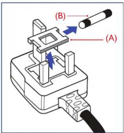
This apparatus is supplied with an approved moulded 13A plug. To change a fuse in this type of plug proceed as follows:
1 Remove fuse cover and fuse.
2 Fit new fuse which should be a BS 1362 5A,A.S.T.A. or BSI approved type.
3 Refit the fuse cover.
If the fitted plug is not suitable for your socket outlets, it should be cut off and an appropriate 3-pin plug fitted in its place.
If the mains plug contains a fuse, this should have a value of 5A. If a plug without a fuse is used, the fuse at the distribution board should not be greater than 5A.

Note:
The severed plug must be destroyed to avoid a possible shock hazard should it be inserted into a 13A socket elsewhere.

natural_image
Diagram of a plug socket with colored wires (green, blue, red) connecting internal components (no text or labels)How to connect a plug
The wires in the mains lead are coloured in accordance with the following code:
BLUE - "NEUTRAL" ("N")
BROWN - "LIVE" ("L")
GREEN & YELLOW - "EARTH" ("E")
- The GREEN & YELLOW wire must be connected to the terminal in the plug which is marked with the letter "E" or by the Earth symbol or coloured GREEN or GREEN & YELLOW.
- The BLUE wire must be connected to the terminal which is marked with the letter "N" or coloured BLACK.
- The BROWN wire must be connected to the terminal which marked with the letter "L" or coloured RED. Before replacing the plug cover, make certain that the cord grip is clamped over the sheath of the lead - not simply over the three wires.
North Europe (Nordic Countries) Information
Placering/Ventilation
VARNING: FÖRSÄKRA DIG OM ATT HUVUDBRYTARE OCH UTTAG ÄR LÄTÄTKOMLIGA, NÄR DU STÄLLER DIN UTRUSTNING PÅPLATS.
Placering/Ventilation
ADVARSEL: S∅RG VED PLACERINGEN FOR, AT NETLEDNINGENS STIK OG STIKKONTAKT ER NEMT TILGÆNGELIGE.
Paikka/Ilmankierto
VAROITUS: SIJOITA LAITE SITEN, ETTÄ VERKKOJOHTO VOIDAAAN TARVITTAESSA HELPOSTI IRROTTAA PISTORASIASTA.
End-of-Life Disposal
Your new Public Information Display contains materials that can be recycled and reused. Specialized companies can recycle your product to increase the amount of reusable materials and to minimize the amount to be disposed of.
Please find out about the local regulations on how to dispose of your old display from your local dealer.
(For customers in Canada and U.S.A.)
This product may contain lead and/or mercury. Dispose of in accordance to local-state and federal regulations. For additional information on recycling contact www.eia.org (Consumer Education Initiative).
Waste Electrical and Electronie Equipment-WEEE
Attention users in European Union private households
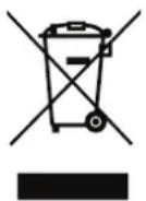
This marking on the product or on its packaging illustrates that, under European Directive 2012/19/EU governing used electrical and electronic appliances, this product may not be disposed of with normal household waste. You are responsible for disposal of this equipment through a designated waste electrical and electronic equipment collection. To determine the locations for dropping off such waste electrical and electronic, contact your local government office, the waste disposal organization that serves your household or the store at which you purchased the product.
Attention users in United States:
Please dispose of according to all Local, State and Federal Laws. For the disposal or recycling information, contact: www.mygreenelectronics.com or www.eiae.org.
End of Life Directives-Recycling

Your new Public Information Display contains several materials that can be recycled for new users.
Please dispose of according to all Local, State, and Federal laws.
Restriction on Hazardous Substances statement (India)
This product complies with the “India E-waste Rule 2011” and prohibits use of lead, mercury, hexavalent chromium, polybrominated biphenyls or polybrominated diphenyl ethers in concentrations exceeding 0.1 weight % and 0.01 weight % for cadmium, except for the exemptions set in Schedule 2 of the Rule.
E-Waste Declaration for India

This symbol on the product or on its packaging indicates that this product must not be disposed of with your other household waste. Instead it is your responsibility to dispose of your waste equipment by handing it over to a designated collection point for the recycling of waste electrical and electronic equipment. The separate collection and recycling of your waste equipment at the time of disposal will help to conserve natural resources and ensure that it is recycled in a manner that protects human health and the environment.
SAFETY INFORMATION
Batteries
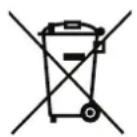
For EU: The crossed-out wheeled bin implies that used batteries should not be put to the general household waste! There is a separate collection system for used batteries, to allow proper treatment and recycling in accordance with legislation.
Please contact your local authority for details on the collection and recycling schemes.
For Switzerland: The used battery is to be returned to the selling point.
For other non-EU countries: Please contact your local authority for correct method of disposal of the used battery.
According to EU directive 2006/66/EC, the battery can't be disposed improperly. The battery shall be separated to collect by local service.
Turkey RoHS
Symbols used in this manual
 | This icon indicates the existence of a potential hazard that could result in personal injury or damage to the product. |
 | This icon indicates important operating and servicing information. |
Notice
- Read this User Manual carefully before using the LCD display and keep it for future reference.
- The product specifications and other information provided in this User Manual are for reference only. All information is subject to change without notice. Updated content can be downloaded from our web site at http://www.agneovo.com.
• To register online, go to http://www.agneovo.com. - To protect your rights as a consumer, do not remove any stickers from the LCD display. Doing so may affect the determination of the warranty period.
Cautions When Setting Up
- Do not place the LCD display near heat sources, such as a heater, exhaust vent, or in direct sunlight.
- Do not cover or block the ventilation holes in the housing.
- Place the LCD display on a stable area. Do not place the LCD display where it may subject to vibration or shock.
- Place the LCD display in a well-ventilated area.
- Do not place the LCD display outdoors.
- To avoid the risk of shock or permanent damage to the set, do not expose the display to dust, rain, water or an excessively moist environment.
- Do not spill liquid or insert sharp objects into the LCD display through the ventilation holes. Doing so may cause accidental fire, electric shock or damage the LCD display.
Cautions When Using
- Use only the power cord supplied with the LCD display.
- The power outlet should be installed near the LCD display and be easily accessible.
- If an extension cord is used with the LCD display, ensure that the total current consumption plugged into the power outlet does not exceed the ampere rating.
- Do not allow anything to rest on the power cord. Do not place the LCD display where the power cord may be stepped on.
- If the LCD display will not be used for an indefinite period of time, unplug the power cord from the power outlet.
- To disconnect the power cord, grasp and pull by the plug head. Do not tug on the cord; doing so may cause fire or electric shock.
- Do not unplug or touch the power cord with wet hands.
- When turning off the display by detaching the power cord, wait 6 seconds before re-attaching the power cord for normal operation.
- Do not knock or drop the display during operation or transportation.
Cleaning and Maintenance
- To protect your display from possible damage, do not put excessive pressure on the LCD panel. When moving your display, grasp the frame to lift; do not lift the display by placing your hand or fingers on the LCD panel.
- Unplug the display if you need to clean it with a slightly damp cloth. The screen may be wiped with a dry cloth when the power is off. However, never use organic solvent, such as, alcohol, or ammonia-based liquids to clean your display.
- If your display becomes wet, wipe it with dry cloth as soon as possible.
- If a foreign substance or water gets in your display, turn the power off immediately and disconnect the power cord. Then remove the foreign substance or water, and send the unit to the maintenance center.
- In order to maintain the best performance of your display and ensure a longer lifetime, we strongly recommend using the display in a location that falls within the following temperature and humidity ranges.
♦ Temperature: 0-40°C (32-104°F)
◆ Humidity: 20-80% RH

Warning:

Unplug the power cord from the power outlet and refer to qualified service
personnel under the following conditions:
- When the power cord is damaged.
If the LCD display has been dropped or the housing has been damaged.
◆ If the LCD display emits smoke or a distinct odor.
Notice for the LCD Display
- In order to maintain the stable luminous performance, it is recommended to use low brightness setting.
- Due to the lifespan of the lamp, it is normal that the brightness quality of the LCD display may decrease with time.
- When static images are displayed for long periods of time, the image may cause an imprint on the LCD display. This is called image retention or burn-in.
◆ To prevent image retention, do any of the following:
- Set the LCD display to turn off after a few minutes of being idle.
- Use a screen saver that has moving graphics or a blank white image.
- Execute the ANTI-BURN-IN function of the LCD display. See "General Settings, ANTI-BURN-IN" section.
- Switch desktop backgrounds regularly.
- Adjust the LCD display to low brightness settings.
- Turn off the LCD display when the system is not in use.
◆ Things to do when the LCD display shows image retention:
- Turn off the LCD display for extended periods of time. It can be several hours or several days.
- Use a screen saver and run it for extended periods of time.
- Use a black and white image and run it for extended periods of time.
- There are millions of micro transistors inside the LCD display. It is normal for a few transistors to be damaged and to produce spots. This is acceptable and is not considered a failure.
- IMPORTANT: Always activate a moving screen saver program when you leave your display unattended. Always activate a periodic screen refresh application if the unit will display unchanging static content. Uninterrupted display of still or static images over an extended period may cause “burn in”, also known as “after-imaging” or “ghost imaging”, on your screen. This is a well-known phenomenon in LCD panel technology. In most cases, the “burned in” or “after-imaging” or “ghost imaging” will disappear gradually over a period of time after the power has been switched off.
- WARNING: Severe "burn-in" or "after-image" or "ghost image" symptoms will not disappear and cannot be repaired. This is also not covered under the terms of your warranty.
CHAPTER 1: PRODUCT DESCRIPTION
1.1 Package Contents
When unpacking, check if the following items are included in the package. If any of them is missing or damaged, contact your dealer.

LCD Display
natural_image
Blank white rectangle with a thin gray border, no text or symbols present.
Quick start guide


Remote control


Power cord
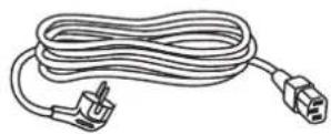

Daisy-chain cable


RS232 cable

natural_image
Line drawing of a cable with two connectors, no text or symbols present
VGA cable

Note:
◆ Remote control is shipped with the supplied AAA batteries.
For all other regions, apply a power cord that conforms to the AC voltage of the power socket and has been approved by and complies with the safety regulations of the particular country.
You might like to save the package box and packing material for shipping the display.
Note:
The pictures are for reference only. Actual items may vary upon shipment.
PRODUCT DESCRIPTION
1.2 Preparing for the Installation
- Due to the high power consumption, always use the plug exclusively designed for this product. If an extended line is required, please consult your service agent.
- The product should be installed on a flat surface to avoid tipping. The distance between the back of the product and the wall should be maintained for proper ventilation. Avoid installing the product in the kitchen, bathroom or any other places with high humidity so as not to shorten the service life of the electronic components.
- The product can normally operate only under 5000m in altitude. In installations at altitudes above 3000m, some abnormalities may be experienced.
1.3 Installing and Removing Table Stands (optional)
To install table stands:
1 Ensure your display is powered off.
2 Spread a protective sheet on a flat surface.
3 Grab the carrying handles and place the display face-down on the protective sheet.
4 After inserting the stand in the guide block, tighten the screws on both sides of the display.
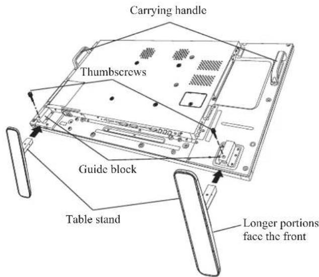
To remove table stands:
1 Power off the display.
2 Spread a protective sheet on a flat surface.
3 Grab the carrying handles and place the display face-down on the protective sheet.
4 Remove screws using a screwdriver and place them in a safe place for reuse.

Warning:
Do not press too hard on the LCD panel or edge of the frame, as this may cause the device to malfunction.
During unpacking, make sure to hold the carrying handles to remove the device from its packaging.
Note:
- The longer side of the stand should face the front of the display.
PRODUCT DESCRIPTION
1.4 Wall Mounting Installation
To mount this display to a wall, you will have to obtain a standard wall-mounting kit (commercially available). We recommend using a mounting interface that complies with TUV-GS and/or UL1678 standard in North America.
To wall-mount the LCD display, screw the mounting bracket to the VESA holes at the rear of the LCD display.

PD-42

PD-49

PD-55
Note:
Avoid the wall-mounting kit to block the ventilation holes on the back of the display.
- Secure the LCD display on a solid wall strong enough to bear its weight.
- Lay a protective sheet on a table, which was wrapped around the display when it was packaged, beneath the screen surface so as not to scratch the screen face.
◆ Ensure you have all accessories for mounting this display (wall mount, ceiling mount, table stand, etc).
Follow the instructions that come with the base mounting kit. Failure to follow correct mounting procedures could result in damage to the equipment or injury to the user or installer. Product warranty does not cover damage caused by improper installation.
PRODUCT DESCRIPTION
1.4.1 VESA Grid
Model Name VESA Grid
| PD-42 200(H) x 200(V) mm | |
| PD-49 400(H) x 400(V) mm | |
| PD-55 400(H) x 400(V) mm |

Caution:
To prevent the display from falling:
For wall or ceiling installation, we recommend installing the display with metal brackets which are commercially available. For detailed installation instructions, refer to the guide received with the respective bracket.
To lessen the probability of injury and damage resulting from fall of the display in case of earthquake or other natural disaster, be sure to consult the bracket manufacturer for installation location.
1.4.2 Ventilation Requirements for Enclosure Locating
To allow heat to disperse, leave space between surrounding objects as shown in the diagram below.

Note:
For the wall-mounting kit, use M6 mounting screws (having a length 10 mm longer than the thickness of the mounting bracket) and tighten them securely.
Unit weight= 15.3 kg (PD-42), 19.0 kg (PD-49) or 24.7 kg (PD-55). The equipment and its associated mounting means still remain secure during the test. For use only with UL Listed Wall Mount Bracket with minimum weight/load: 19.5 kg (PD-42), 24.9 kg (PD-49) or 31.1 kg (PD-55).
1.5 Mounting in Portrait Position
This display can be installed in portrait position.
1 Remove the table stand, if attached.
2 Rotate 90 degrees counter-clockwise.


1.6 Using the Remote Sensor and Power Status Indicator
- If you want to obtain a better reception of remote control function, please adjust the indicator location to easily check the power status indicator.
- If the display is mounting on the wall, please pull the indicator switch upwards before installation.
- When adjusting the indicator location, make sure to push/pull the indicator switch firmly until it clicks into place.

natural_image
Simple diagram showing a monitor with an eye and a battery, no text or symbols presentPull upwards to hide the indicator

natural_image
Simple diagram with a download arrow and circular symbol, enclosed in a dashed border (no text or labels)Push downwards to reveal the indicator
PRODUCT DESCRIPTION
1.7 LCD Display Overview
1.7.1 Control Panel

PD-42

PD-49
PRODUCT DESCRIPTION

PD-55
1 [+] Power
Turn the display on or put the display to standby.
2 MUTE
Switch the audio mute ON/OFF.
3 INPUT
- Choose the input source.
• Used as the OK button while OSD menu is on.
4 [+] Increase
- Increase the adjustment while OSD menu is on.
- Increase the audio output level while OSD menu is off.
5 [—] Decrease
- Decrease the adjustment while OSD menu is on.
• Decrease the audio output level while OSD menu is off.
6 [▲] Up
Move the highlight bar up to adjust the selected item while OSD menu is on.
7 [▼] Down
Move the highlight bar down to adjust the selected item while OSD menu is on.
8 MENU
- Return to the previous menu while OSD menu is on.
- Activate the OSD menu when OSD menu is off.
9 Remote control sensor and power status indicator
- Receive command signals from the remote control.
-
Indicate the operating status of the display without OPS:
-
Lights green when the display is turned on
- Lights amber when the display is in standby mode
- Lights off when the main power of the display is turned off
1.7.2 Input/Output Terminals

PD-42
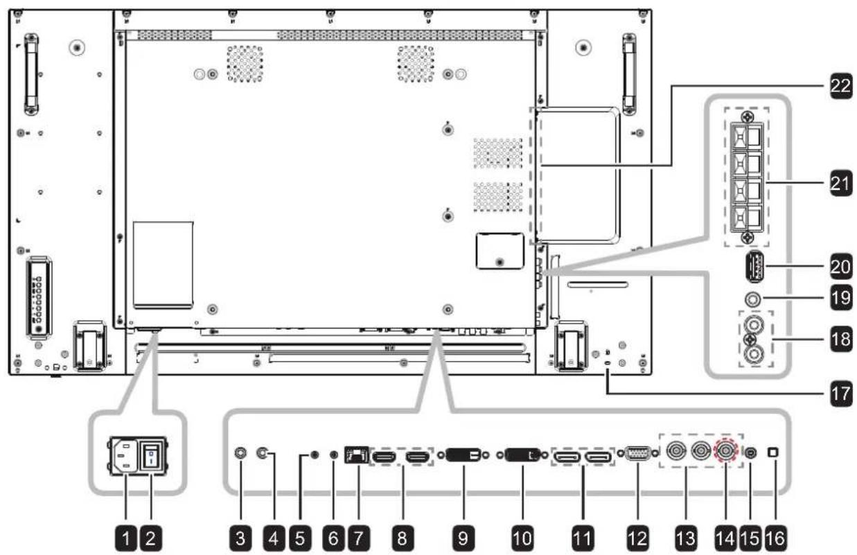
PD-49
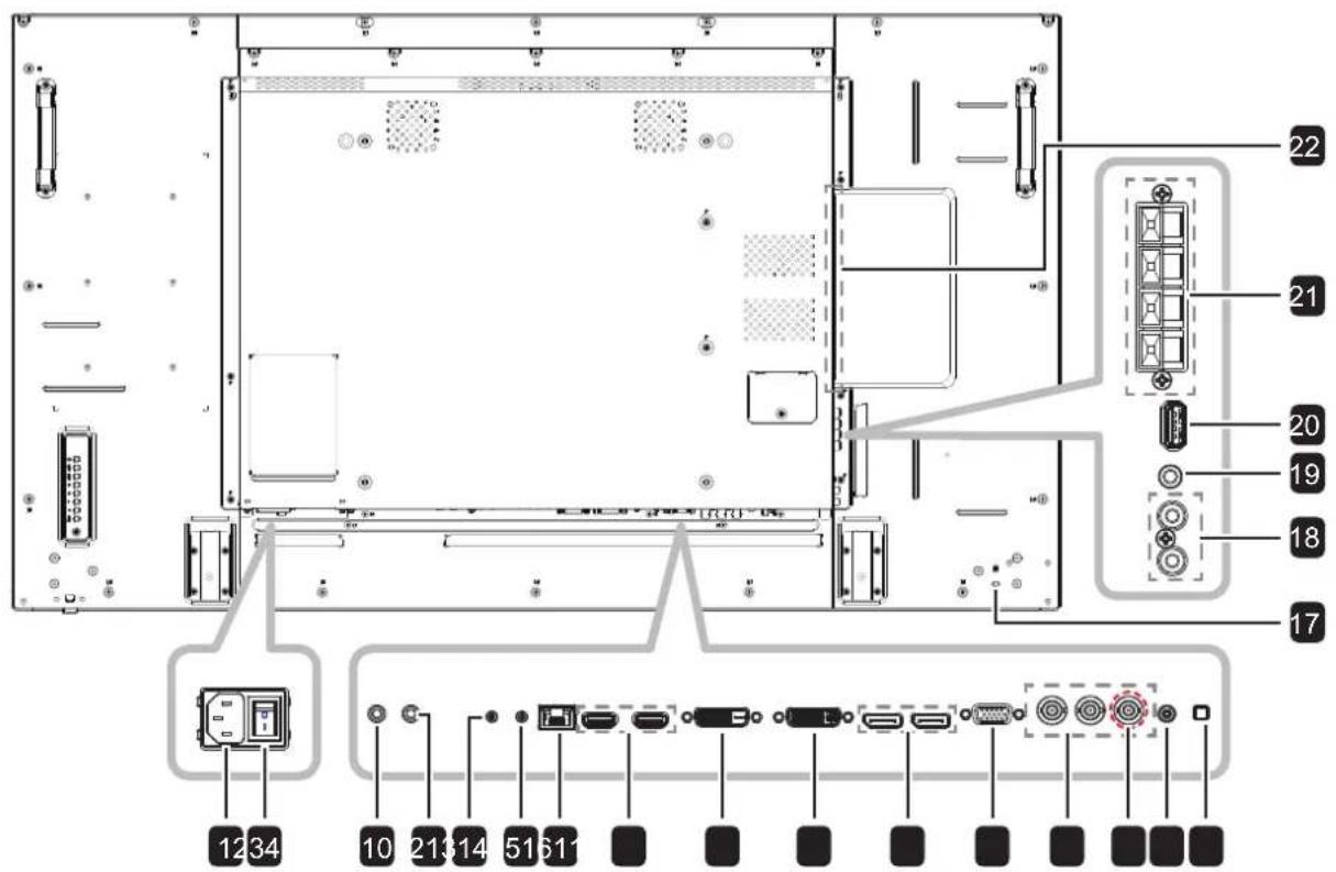
PD-55
1 AC IN
AC power input from the wall outlet.
2 Main power switch
Switch the main power on/off.
3 IR IN/IR OUT
& IR signal input / output for the loop-
4 through function.
Note:
This display's remote control sensor will stop working if the [IR IN] jack is connected.
To remotely control your A/V device via this display, refer to page 33 for IR Pass-Through connection.
5 RS232C IN/ RS232C OUT
& RS232C network output / input for the
6 loop-through function.
7 RJ-45
LAN control function for the use of remote control signal from the control center.
8 HDMI1 IN/ HDMI2 IN
HDMI video/audio input.
9 DVI IN
DVI-D video input.
10 DVI OUT
DVI, VGA, HDMI, or OPS video output.
11 DisplayPort IN/ DisplayPort OUT
DisplayPort video input / output.
12 VGA IN (D-Sub)
VGA video input.
13 COMPONENT IN (BNC)
Component YPbPr video source input.
14 Y/CVBS
Video source input.
15 PC Audio In
Audio input for PC source (3.5mm stereo phone).
16 SPEAKER SWITCH
Select the internal or external speaker.
17 SECURITY LOCK
Used for security and theft prevention.
18 AUDIO IN
Audio input from external AV device (RCA).
19 AUDIO OUT
Audio output to external AV device.
20 USB(F/W)
Connect your USB storage device (for FW update / media playback).
21 SPEAKERS
Audio output to external speakers.
22 OPS SLOT
Slot for installing the optional OPS module.
PRODUCT DESCRIPTION
1.8 Remote Control
1.8.1 General Functions


POWER
Turn the display on or to put the display into standby mode.

PLAY
Control playback in multimedia mode.

[SOURCE]
Choose input source. Press the ☐ or Button to choose from USB, Network, HDMI 1, HDMI 2, DisplayPort, Card OPS, DVI-D, YPbPr, AV, or VGA. Press the OK button to confirm and exit.
![AG Neovo PD-55 - [SOURCE] - 1](/content/2026/05/1084861/images/f24b13844a29569dbf088d85ce09555377466e5e6b7d4d674af3c96f49cdef40.jpg)
[↑HOME]
Access the OSD menu.
![AG Neovo PD-55 - [↑HOME] - 1](/content/2026/05/1084861/images/3f375db134b2ff181ebb340d3167d8cab53b9967f16931a94c98baa9b5a9358c.jpg)
[LIST
No function.

[1] [7] [+] [ ]-NAVIGATION buttons
Navigate through menus and choose items.
![AG Neovo PD-55 - [1] [7] [+] [ ]-NAVIGATION buttons - 1](/content/2026/05/1084861/images/9650602d8d89fa52bbcd54953bd99861bd0f65fae4efa08d8e2124697a8c2546.jpg)
[∅QK
Confirm an entry or selection.

[↑]ADJUST
Access currently available picture and sound menus.
![AG Neovo PD-55 - [↑]ADJUST - 1](/content/2026/05/1084861/images/906826ced711f42ba0ea4d7ea7d9270c4b4c9a238eefbaee9e9bc206eeeede49.jpg)
[1]MUTE
Turn the mute function on/off.
![AG Neovo PD-55 - [1]MUTE - 1](/content/2026/05/1084861/images/9d8d64438e2c3d773863c053fcc495f6d49eb3e45788a6529080f404700b7b86.jpg)
[][][][] COLOR
Used for USB Device or Options.
• Red: Press to play all songs in the playlist.
- Green: Press to sort the playlist.
- Yellow: Press to view the USB device.
- Blue: No function
Note:
- While OSD menu is on, press the button to return to the previous menu.

[Number/ ID SET/ ENTER]
- Enter text for network setting.
- Set the display ID. Refer to 1.8.2 ID Remote Control for more detail.
![AG Neovo PD-55 - [Number/ ID SET/ ENTER] - 1](/content/2026/05/1084861/images/e700909d672f581d590325db66117369f288f3a90a1df3a751455fa825b0c4fb.jpg)
FORMAT
Change the aspect ratio.

[←] BACK
Return to the previous menu or exit from the previous function.

![AG Neovo PD-55 - [←] BACK - 2](/content/2026/05/1084861/images/efaf78b4fb64819fb083476f837a7247c2da2a4b200d682b3920149ae067ea90.jpg)
[ ]iNFO
View the information about the display.
![AG Neovo PD-55 - [ ]iNFO - 1](/content/2026/05/1084861/images/3cea807e8df19c90bcfe4d68dbae05deaebfca748bcb47841d9f0b9f7f1ddbb9.jpg)
OPTIONS
Access currently available options, picture, and sound menus.
Note:
In multimedia mode, user can adjust the picture, sound, ECO, and clock settings.

[一][+]VOLUME
Adjust the volume level.
PRODUCT DESCRIPTION
1.8.2 ID Remote Control
You can set the remote control ID when you want to use this remote control on one of several different displays.

To set the remote control ID:
1 Press the ID button. The red LED blinks twice.
2 Press the ID SET button for 3 seconds to enter the ID mode. The red LED lights up.
Press the ID SET button again will exit the ID mode. The red LED lights off.
3 Press the digit numbers [0] \~ [9] to select the display you want to control. For example:
- Display ID #1: press [0], [0], [1]
- Display ID #11: press [0], [1], [1]
The numbers available are from [001] \~ [255].
- Not pressing any button within 10 seconds will exit the ID mode.
- If an error pressing of buttons other than the digits occurred, wait 1 second after the red LED lights off and then lights up again, then press the correct digits again.
4 Press the ENTER button to confirm. The red LED blinks twice and then lights off.
Note:
- Press the NORMAL button. The green LED blinks twice, indicating the remote control returns to normal operation.
It is necessary to set up the ID number for each display before selecting its ID number.
PRODUCT DESCRIPTION
1.8.3 Inserting the Batteries in the Remote Control
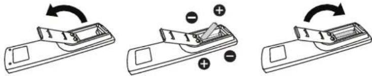
The remote control is powered by two 1.5V AAA batteries.
To install or replace batteries:
1 Press and then slide the cover to open it.
2 Align the batteries according to the (+) and (-) indications inside the battery compartment.
3 Replace the cover.
natural_image
Three-step diagram showing a device with a handle, a triangular component, and a curved arrow indicating rotation (no text or symbols)1.8.4 Handling the Remote Control
- Do not subject to strong shock.
- Do not allow water or other liquid to splash the remote control. If the remote control gets wet, wipe it dry immediately.
- Avoid exposure to heat and steam.
- Other than to install the batteries, do not open the remote control.
1.8.5 Operating Range of the Remote Control
Point the top of the remote control toward the display's remote control sensor(back side) when pressing a button.
Use the remote control within the range which is shown in the following table.
| Operation Angle RC operational distance |
| θ = 0irc (for H & V) ≥ 8m |
| θ = 20irc (for H & V) ≥ 5m |
| θ = 45irc (for H only) ≥ 2m |


Caution:
The incorrect use of batteries can result in leaks or bursting. Be sure to follow these instructions:
Place "AAA" batteries matching the (+) and (−) signs on each battery to the (+) and (−) signs of the battery compartment.
♦ Do not mix battery types.
Do not combine new batteries with used ones. It causes shorter life or leakage of batteries.
Remove the dead batteries immediately to prevent them from liquid leaking in the battery compartment. Don't touch exposed battery acid, as it can damage your skin.
Note:
If you do not intend to use the remote control for a long period, remove the batteries.
The remote control may not function properly when the remote control sensor on this display is under direct sunlight or strong illumination, or when there is an obstacle in the path of signal transmission.
CHAPTER 2: MAKING CONNECTIONS
2.1 Connecting the Power
1 Connect one end of the power cord to the AC IN connector at the rear of the LCD display.
2 Connect the other end of the power cord to a power outlet or a power supply.
3 Set the Main Power switch to ON.
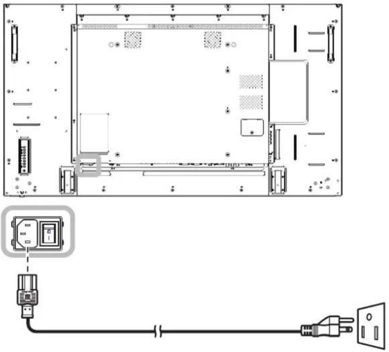
natural_image
Technical line drawing of an electronic device rear panel with a close-up of its internal components connected to a power outlet (no text or symbols present)
Caution:
Make sure that the LCD display is not connected to the power outlet before making any connections. Connecting cables while the power is ON may cause electric shock or personal injury.
When unplugging the power cord, hold the power cord by the plug head. Never pull by the cord.
MAKING CONNECTIONS
2.2 Connecting a Computer
2.2.1 Using VGA Input
Connect one end of a D-sub cable to the VGA IN connector of the LCD display and the other end of a D-sub cable to the VGA OUT (D-Sub) connector of the computer.
For audio input, connect one end of an audio cable to the AUDIO IN connector of the LCD display and the other end of an audio cable to the AUDIO OUT connector of the computer.

2.2.2 Using DVI Input
Connect one end of a DVI cable to the DVI IN connector of the LCD display and the other end of a DVI cable to the DVI connector of the computer.

MAKING CONNECTIONS
2.2.3 Using HDMI Input
Connect one end of an HDMI cable to the HDMI1 IN/ HDMI2 IN connector of the LCD display and the other end of an HDMI cable to the HDMI OUT connector of the computer.

2.2.4 Using DisplayPort Input
Connect one end of a DisplayPort cable to the DisplayPort IN connector of the LCD display and the other end of a DisplayPort cable to the DisplayPort OUT connector of the computer.
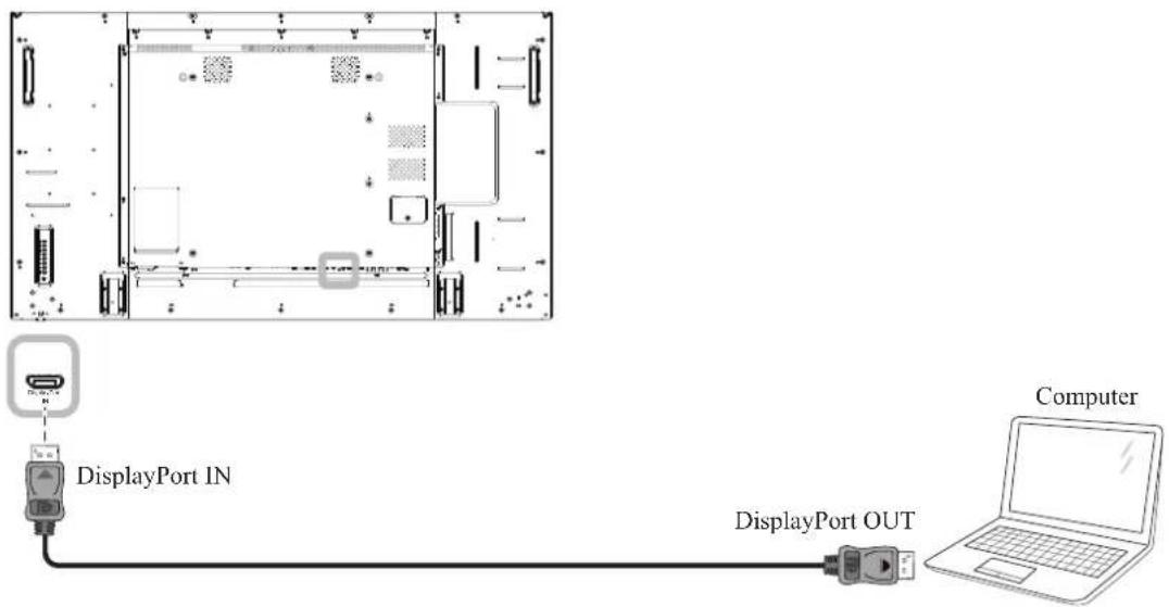
flowchart
graph TD
    A["DisplayPort IN"] --> B["Computer"]
    C["DisplayPort OUT"] --> B
MAKING CONNECTIONS
2.3 Connecting External Equipment (DVD / DVD-B)
2.3.1 Using COMPONENT Video Input
Connect one end of a component cable to the COMPONENT IN connector of the LCD display and the other end of a component cable to the COMPONENT OUT connectors of the video player (DVD / DVD-B).
For audio input, connect one end of an audio cable to the AUDIO IN connectors of the LCD display and the other end of an audio cable to the AUDIO OUT connectors of the video player (DVD / DVD-B).

flowchart
graph TD
    A["Component IN (YPbPr)"] --> B["Audio IN"]
    B --> C["R"]
    B --> D["L"]
    B --> E["AUDIO OUT"]
    E --> F["DVD / DVD-B"]
    B --> G["COMPONENT OUT (YPbPr)"]
    G --> H["Component IN (YPbPr)"]
2.3.2 Using Video Source Input
Connect one end of a video cable to the Y/CVBS in port of the LCD display and the other end of a video cable to the Y/CVBS out port of the the video player (DVD / DVD-B).
For audio input, connect one end of an audio cable to the AUDIO IN connectors of the LCD display and the other end of an audio cable to the AUDIO OUT connectors of the video player (DVD / DVD-B).

MAKING CONNECTIONS
2.3.3 Using HDMI Video Input
Connect one end of an HDMI cable to the HDMI1 IN/ HDMI2 IN connector of the LCD display and the other end of an HDMI cable to the HDMI out connector of the video player (DVD / DVD-B).

2.4 Connecting Audio Equipment
2.4.1 Connecting External Speakers
Press the Speaker Switch and connect the speakers cables to the SPEAKERS connector of the LCD display.

MAKING CONNECTIONS
2.4.2 Connecting an External Audio Device
Connect one end of an audio cable to the AUDIO OUT connector of the LCD display and the other end of an audio cable to the AUDIO IN connector of the audio device.

MAKING CONNECTIONS
2.5 Connecting Multiple Displays in a Daisy-chain Configuration
You can interconnect multiple displays to create a daisy-chain configuration for applications such as a video wall.

Caution:
To avoid unnecessary strain on the bezel, it is highly recommended to keep a minimum space of 0.5mm in which a business card is able to slip between all displays on all sides.

2.5.1 Display Control Connection
Connect the RS232C OUT connector of DISPLAY 1 to the RS232C IN connector of DISPLAY 2.

flowchart
graph LR
    PC["PC"] -->|[RS-232C]| USB1["USB"]
    USB1 -->|[RS-232C IN]| DISPLAY1["DISPLAY 1"]
    DISPLAY1 -->|[RS-232C OUT] | DISPLAY2["DISPLAY 2"]
    DISPLAY2 -->|[RS-232C IN]| USB2["USB"]
2.5.2 Digital Video Connection
Connect the DVI OUT connector of DISPLAY 1 to the DVI IN connector of DISPLAY 2.
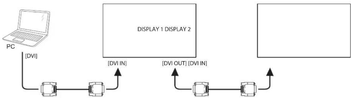
flowchart
graph TD
    PC["PC"] -->|DVI| A["Device 1"]
    A -->|DVI IN| B["Display 1 DISPLAY 2"]
    B -->|DVI OUT| C["Device 2"]
    C -->|DVI IN| A
    C -->|DVI OUT| B
MAKING CONNECTIONS
Connect the DisplayPort OUT connector of DISPLAY 1 to the DisplayPort IN connector of DISPLAY 2.

flowchart
graph TD
    PC["PC"] -->|[DP]| A["Device 1"]
    A -->|[DP IN]| B["Device 2"]
    B -->|[DP OUT] | C["Device 3"]
    C -->|[DP IN]| A
Note:
Before selecting the DisplayPort 1.1a (DP 1.1a) version, make sure the Tiling > Enable setting is set to Off.
When using DP 1.1a, each display will clone the same content as the source.
◆ DP 1.2 supports MST up to 4 displays.
Connect the DVI OUT connector of DISPLAY 1 to the DVI IN connector of DISPLAY 2.
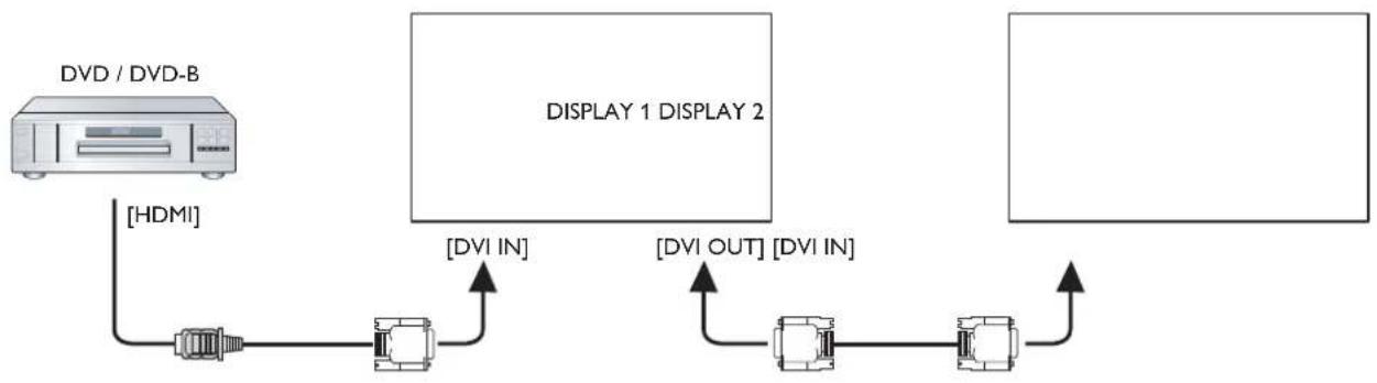
flowchart
graph LR
    A["DVD / DVD-B"] -->|HDMI| B["Link"]
    B --> C["DVI IN"]
    C --> D["Display 1 DISPLAY 2"]
    D --> E["DVI OUT"]
    E --> F["Display 2"]
    F --> G["Output"]
Connect the DVI OUT connector of DISPLAY 1 to the DVI IN connector of DISPLAY 2.

flowchart
graph TD
    A["OPS"] --> B["DISPLAY 1"]
    C["DISPLAY 2"] --> D["DISPLAY 2"]
    B --> E["[DVI OUT"] [DVI IN]]
    D --> E
    E --> F["Output"]
MAKING CONNECTIONS
2.5.3 Analog Video Connection
Connect the DVI OUT connector of DISPLAY 1 to the VGA IN connector of DISPLAY 2.
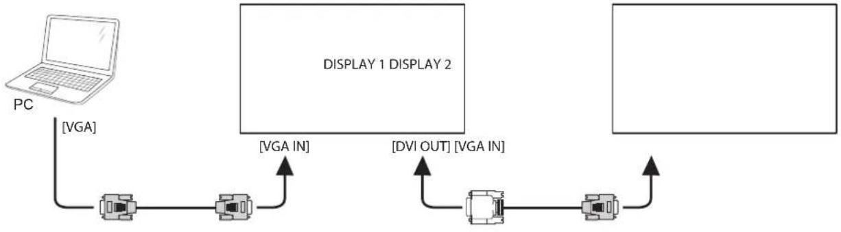
flowchart
graph LR
    PC["PC"] -->|VGA| A["Device 1"]
    A -->|VGA IN| B["Display 1"]
    B -->|DVI OUT| C["Device 2"]
    C -->|VGA IN| A
    A -->|VGA IN| B
    B -->|DVI OUT| C
2.6 IR Connection
Connect the IR sensor cable to the IR IN connector of the LCD display.
![External IR Receiver DISPLAY [IR IN]](/content/2026/05/1084861/images/e4c1193cc47bf38734f96f7d4e7f56d2a6978f17ecb7ad580e478c22983bbbfb.jpg)
Note:
This display's remote control sensor will stop working if the [IR IN] is connected.
MAKING CONNECTIONS
2.7 IR Pass-Through Connection
Connect one end of an IR extender cable to the IR OUT connector of the LCD display and the other end of an IR extender cable to the IR IN connector of the video player (DVD / DVD-B).
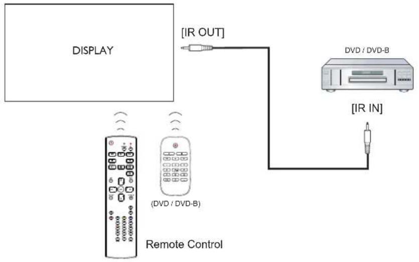
flowchart
graph TD
    A["DISPLAY"] -->|IR OUT| B["DVD / DVD-B"]
    B -->|IR IN| C["Remote Control"]
    D["(DVD / DVD-B)"] --> A
    E["(IR IN)"] --> C
2.8 Connecting to Wired Network
If you connect this LCD display to a home network, you can play photos, music, and videos from your computer.

flowchart
graph TD
    PC["PC"] -->|[RJ-45]| Router["Router"]
    Router -->|INTERNET| Internet["Internet"]
    Router -->|INTERNET| Display["DISPLAY"]
To setup the network:
1 Switch on the router and switch on its DHCP setting.
2 Connect the router to the LCD display with an Ethernet cable.
3 Press the ↑ button to display the OSD menu.
4 Press the ▲ or ▶ button to select Network settings. Press the OK button to enter its submenu.
5 Press the ▲ or ▼ button to select Network configuration. Press the OK to enter its submenu.
6 Press the ↓ or ↑ button to select DHCP & Auto IP. Press the OK button to confirm.
Note:
- Connecting with a shielded CAT-5 Ethernet cable to comply with the EMC directive.
To manually configure the network parameters, set the Network configuration setting to Static IP.
CHAPTER 3: USING THE LCD DISPLAY
3.1 Turning on the Power
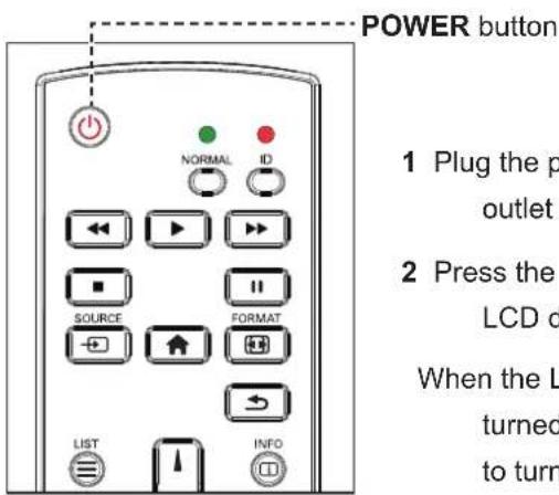
1 Plug the power cord to a power outlet or power supply.
2 Press the ⏻ button to turn the LCD display on.
When the LCD display is turned on, press the ⏻ button to turn off the LCD display.
3.2 Selecting the Input Source Signal
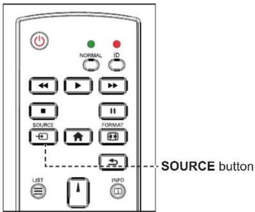
1 Press the button.
2 Press the ▲ or ▼ button to choose a device, then press the OK button.
Note:
The LCD display still consumes power as long as the power cord is connected to the power outlet. Disconnect the power cord to completely cut off power.
Note:
After pressing the button, a menu with available input sources will be displayed on the screen.

If the selected input source signal is not connected to the LCD display or is turned off, the no signal message is displayed on the screen.

No signal
USING THE LCD DISPLAY
3.3 Adjusting the Volume
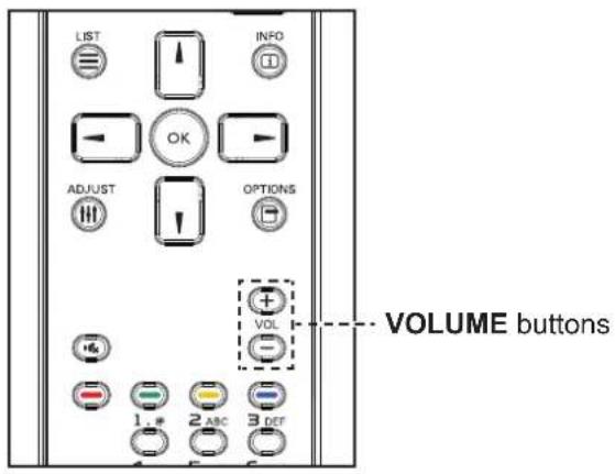
Press the -or button to adjust the volume.
3.4 Changing the Picture Format
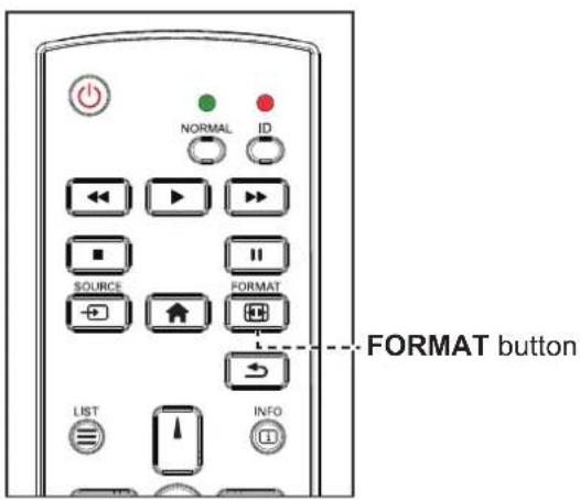
1 Press the button.

2 Press the or button to choose a picture format, then press the OK button.
Note:
After pressing the—or + button, the volume icon is displayed on the screen automatically.

- Press the button to mute the audio.
Note:
The available picture formats include:
Auto zoom: Enlarge the picture to fill the screen. Recommended for minimal screen distortion but not for HD or PC.
♦ Movie expand 16:9: Scale 4:3 format to 16:9. Not recommended for HD or PC.
- Wide screen: Shows wide screen format content unstretched. Not recommended for HD or PC.
Unscaled: Provide maximum detail for PC. Only available when PC mode is selected in the Picture menu.
◆ 4:3: Display the classic 4:3 format.
USING THE LCD DISPLAY
3.5 Choosing Your Preferred Picture Settings
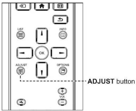
1 While this display is playing video source, press the button.
2 Press the or button to choose Picture style, then press the OK button.
3 Press the ▲ or ▼ button to choose an option, then press the OK button.

3.6 Choosing Your Preferred Sound Settings

1 While this display is playing video source, press the button.
2 Press the or button to choose Sound style, then press the OK button.
3 Press the ▲ or ▼ button to choose an option, then press the OK button.

Note:
The available picture styles include:
◆ Personal: Apply your personalised picture settings.
♦ Vivid: Rich and dynamic settings, ideal for daytime viewing.
♦ Natural: Natural picture settings.
Standard: Default settings that suit most environments and types of video.
◆ Movie: Ideal settings for movies.
◆ Photo: Ideal settings for photos.
◆ Energy saving: Settings that conserve the most energy.
Note:
The available sound settings include:
◆ Personal: Apply your personalised sound settings.
♦ Original: Settings that suit most environments and types of audio.
◆ Movie: Ideal settings for movies.
◆ Music: Ideal settings for listening to music.
◆ Game: Ideal settings for games.
◆ News: Ideal settings for spoken audio, such as the news.
3.7 Playing Multimedia Files via Local Area Network
To play files via Local Area Network, you will need:
- A wired home network, connected with a Universal Plug and Play (uPnP) router.
- Optional: A LAN cable that connects your display to your home network.
- A media server running on your computer.
- Appropriate settings on your computer firewall to allow you to run the media server.
3.7.1 Set Up the Network
1 Connect your display and the computer to the same home network. See illustration below to connect your display to a network.
2 Switch on your computer and the router.
- Single display setup:
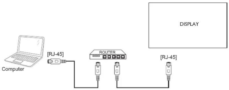
flowchart
graph LR
    A["Computer"] --> B["RJ-45"]
    B --> C["ROUTER"]
    C --> D["RJ-45"]
    D --> E["DISPLAY"]
- Multiple display setup:

flowchart
graph LR
    A["Computer"] --> B["RJ-45"]
    B --> C["ROUTER"]
    C --> D["DISPLAY 1"]
    C --> E["DISPLAY 2"]
    C --> F["RJ-45"][RJ-45]
Note:
If the apparatus does not return to DLNA mode due to external electrical disturbances (e.g. electrostatic discharge), user intervention is required.
Set Up Media Sharing
1 Install a media server on your computer to share media files. These are some media servers:
- For PC: Windows Media Player 11 (or higher) or TVersity
- For Mac: Twonky
2 Switch on media sharing on your computer using the media server. For more information on how to set up the media server, refer to the website of the media server.
3.7.2 How to Use DLNA-DMP
1 Please connect display and your PC to the same router via RJ-45.
2 Run windows media player. Set stream handling as public sharing.
Play Files from Display
1 Press the button, choose network and press the OK button.

2 Now, you can see all the PC's connected to the same router on the screen. Choose the right one.
3 Press the ▼ or ▶ button to choose the directory and files to play.
4 You can connect up to 4 displays to the same PC and play same media stream.
We suggest to use DLNA-DMP function via wired network for the sake of higher security and sufficient network bandwidth.
3.7.3 How to Use DLNA-DMR from PC
1 Press the ⬆ button. Then choose Network settings and press the OK button.
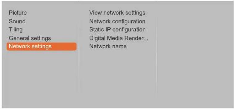
2 Set the Digital Media Renderer -DMR setting to On.
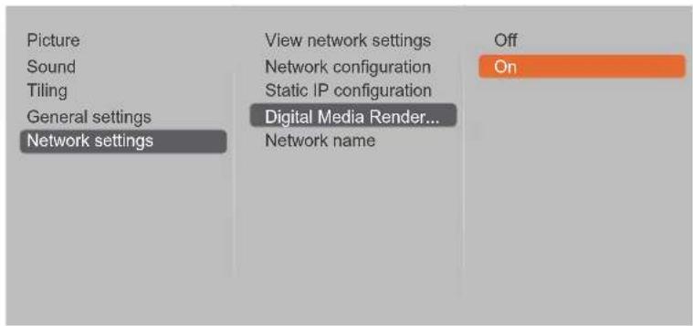
3 Set the name of your display.


4 Press the button, choose Network and press the button OK
5 On your PC, go to Network and Sharing Center, and click Choose homegroup and sharing options.
6 Check the media formats. Then, click Choose media streaming options.....
7 Go to Advanced sharing settings, and check Turn on network discovery.
USING THE LCD DISPLAY
8 Now, go to the directory of your media files. Choose the media file by right click. On the submenu from Play To, You can find all displays connected to your network. Choose the display, and click the media file to play.
Play Files
1 Press the button. Then choose Network and press the OKton.
2 Choose a file from the content browser, and press the OK button to start playing.
3 Press the PLAY buttons (◀◀, ▶, ▶) on the remote control to control the media playback.
Tips:
- Choose the top bar to filter your files by type.
- Choose Sort to arrange the files by album name, artist, or other fields.
- To clear the list of offline media servers, press the ☐ button. Then, choose Clear offline servers and press the OK button.
3.8 Playing Multimedia Files from USB Device
1 Connect your USB device to the USB(F/W) connector on the LCD display.
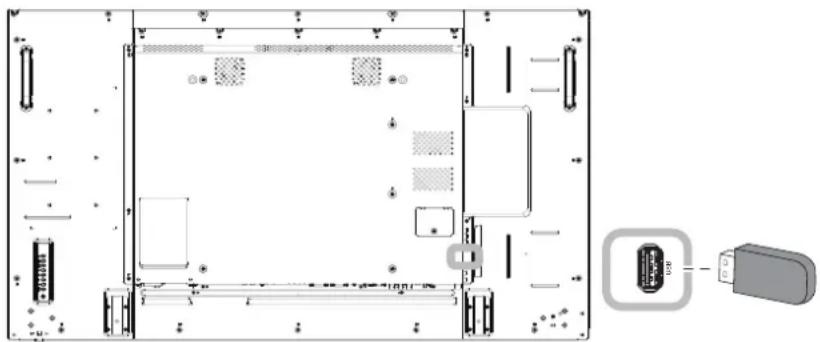
natural_image
Technical diagram of a server rack layout with connectors and a close-up of the internal component (no text or labels visible)2 Press the → button. Then choose USB, and press the OK button.

USING THE LCD DISPLAY
3 Press the button to enter the USB mode.

4 By default, it displays the files in Folder view.
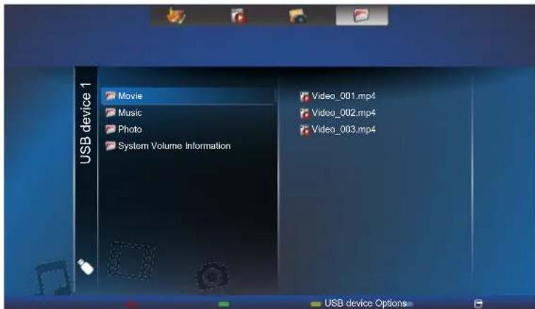
Press the ▲ button to go up the top layer in the screen. Then press the — or — button to select the desired file type: Music, Movie, and Photos
5 Press the OK button to enter its play list.
5 Choose the file you want. Press the button to start playing.
6 Follow the on-screen instructions to control the play option.
7 Press the PLAY buttons (◀◀, ,▶, ,▶) on the remote control to control the media playback.
3.9 Play Options
3.9.1 Playing Music Files
1 Choose Music in the top bar.

2 Choose one music track, and press the button.
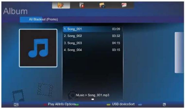
• To play all the tracks in a folder, choose one music file. Then, press the — button to Play All.
• To view USB device, press the button.
- To skip to the next or previous track, press the ▲or ▲button.
- To pause the track, press the OK or button. Press the OK button again to resume playback.
- To skip backward or forward 10 seconds, press the → or → button.
- To search backward or forward, press the ◀◀ or ▶button, press repeatedly to toggle between different speeds.
• To stop the music, press the ■ button.
Music options
While you play music, press the ☐ button, then use the ↓, ↑, ←, or → to choose an option. Then press the OK button to select an option:
- Shuffle: Enable or disable random play of tracks.
- Repeat: Choose Repeat to play a track or an album repeatedly, or choose Play Once to play a track once.
Note:
To view information about a song (for example, title, artist or duration), choose the song, then press the button. To hide the information, press the button again.
3.9.2 Playing Movie Files
1 Choose Movie in the top bar.

2 Choose a video, and press the butok
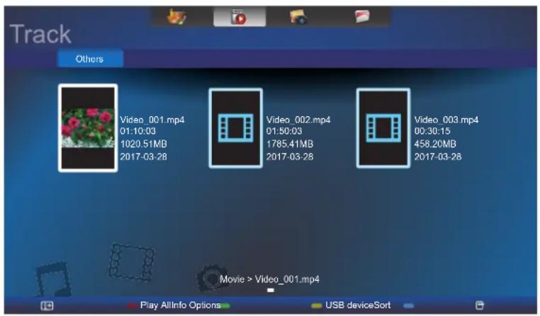
- To play all the videos in a folder, choose one video file. Then, press the — button to Play All.
- To view USB device, the button.
- To pause the video, press the OK button. Press the or button again to resume playback.
- To skip backward or forward 10 seconds, press the ← or → button.
- To search backward or forward, press the ◀◀ or ▶button, press repeatedly to toggle between different speeds.
- To stop the video, press the ■ button.
Movie options
While playing video, press the ☐ button, then use ↓, ↑, ←, or → to choose an option. Then press the OK button to select an option:
- Subtitles: Choose the available subtitle settings.
- Shuffle: Enable or disable random play of video files.
- Repeat: Choose Repeat to play the video file repeatedly or Play Once to play the video file once.
3.9.3 Playing Photo Files
1 Choose Photo in the top bar.

2 Choose a photo thumbnail, then press the butok

Start a Slideshow
If there are multiple photos in a folder, choose a photo. Then, press the — button to Play All.
- To skip to the previous or next photo, press the - or -button, and then press the button.
• To stop the slideshow, press the ■ button.
Slideshow options
While you play a slideshow, press the button, then press the button to choose an option:
- Shuffle: Enable or disable random display of pictures in the slideshow.
- Repeat: Choose Repeat to watch a slideshow repeatedly or Play Once to watch once.
- Slideshow Time: Choose the displaying time for each photo in the slideshow.
- Slideshow Transitions: Choose the transition from one photo to the next.
CHAPTER 4: ON SCREEN DISPLAY MENU
4.1 Using the OSD Menu
| # Menu Navigation | Operation | ||
| Control Panel Remote Control | |||
| 1 | Display the main menu screen. | Press the MENU button. | Press the ↑ button. |
| 2 | Enter the submenu. | 1 Press the ▲ or ▼ button to select the menu item.2 Press the INPUT button to enter the submenu. | 1 Press the ↓ or ↓ button to select the menu item.2 Press the OK or ▶ button to enter the submenu. |
| 3 | Adjust the settings.The highlighted item indicates the active submenu.For example: | 1 Press the ▲ or ▼ button to adjust the value of the menu item.2 Press the INPUT button to confirm. | 1 Press the ↓ or ↓ button to adjust the value of the menu item.2 Press the OK button to confirm. |
ON SCREEN DISPLAY MENU
| # | Menu Navigation | Operation | |
| Control Panel Remote Control | |||
| 4 | Exit the submenu. Press the button | — to return to the previous menu. | Press the ↗ or — button to return to the previous menu. |
| 5 | Close the OSD window. Press the MENU | button again. | Press the ↗ button again. |
When settings are modified, all changes are saved when the user does the following:
• Proceeds to the another menu.
- Exits the OSD menu.
- Waits for the OSD menu to disappear.
Note:
◆ Availability of some menu items depend on the input source signal.
ON SCREEN DISPLAY MENU
4.2 OSD Menu Tree
1
Picture
2
Sound
3
Tiling
4
General settings
5
Network settings
Picture style
Restore style
Backlight
Colour
Sharpness
Noise reduction
MPEG artifact reducti...
Digital Crystal Clear
Advanced
Game or computer
HDMI input range
| Main Menu Submenu Remarks | ||
| 1. Picture • Picture style | Restore styleBacklightColourSharpnessNoise reductionMPEG artifact reductionDigital Crystal ClearAdvancedGame or computerHDMI input rangeFormat and edgesInput resolution (for VGA input only) | See page 49. |
| 2. Sound • Sound style | Restore styleBassTrebleBalanceSurround modeAudio outAdvanced | See page 53. |
| 3. Tiling • Enable | H monitorsV monitorsPositionFrame comp. | See page 54. |
ON SCREEN DISPLAY MENU
| Main Menu Submenu Remarks | ||
| 4. General settings • Menu language | Monitor IDAuto searchClockSchedulingSleep timerEasyLinkAuto adjust (for VGA input only)Local KB lockRC lockANTI-BURN-INSmart powerWake on lanSwitch on stateLEDSwitch on delayLogoAPMInformation OSDDisplayPort Ver.Cooling fanNetwork control portFactory settings | See page 56. |
| 5. Network settings • View network settings | Network configurationStatic IP configurationDigital Media Renderer - DMRNetwork name | See page 64. |
Note:
◆ Availability of some menu items depend on the input source signal.
CHAPTER 5: ADJUSTING THE LCD DISPLAY
5.1 Picture Settings
Picture
Sound
Tiling
General settings
Network settings
Picture style
Restore style
Backlight
Colour
Sharpness
Noise reduction
MPEG artifact reducti...
Digital Crystal Clear
Advanced
Game or computer
HDMI input range
1 Press the MENU button on the control panel or the 🔗 button on the remote control to call out the OSD window.
2 Select Picture, then press the INPUT button on the control panel or the OK button on the remote control.
3 Press the ▲▼ button on the control panel or the √ button on the remote control to select an option.
| Item Function Operation Range | |||
| Picture style Choose a predefined picture setting. | Press the ▲▼button on the control panel or the √ button on the remote control to select the setting. | Personal Vivid Natural Standard Movie Photo Energy saving | |
| Restore style | Restore the last-selected predefined picture setting. | Press the +/−button on the control panel or the − button on the remote control to select the setting. | Yes No |
| Backlight | Adjust the brightness of this display's backlight. | Press the ▲▼button on the control panel or the √ button on the remote control to adjust the value. | 0 to 100 |
| Colour | Adjust the colour saturation of the picture. | Press the ▲▼button on the control panel or the √ button on the remote control to adjust the value. | 0 to 100 |
| Sharpness | Adjust the clarity and focus of the screen image. | Press the ▲▼button on the control panel or the √ button on the remote control to adjust the value. | 0 to 20 |
ADJUSTING THE LCD DISPLAY
| Item Function Operation Range | ||||
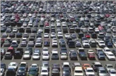
| Noise reduction | Adjust the noise reduction to help remove noise from images. This helps produce clearer and crisper images. | Press the ▲▼button on the control panel or the √l button on the remote control to select the setting. | OffMinimumMediumMaximum | |
| Noise Reduction Off Noise Reduction On | ||||
 |  | |||
| MPEG artifact reduction | Smoothen transitions and haziness in the digital picture. | Press the ▲▼button on the control panel or the √l button on the remote control to select the setting. | OffOn | |
| Digital Crystal Clear | Fine-tune each pixel to match surrounding pixels and produce a brilliant, high-definition image. | |||
| • Advanced sharpness: Enable superior sharpness, especially on lines and contours in the picture. | Press the ▲▼button on the control panel or the √l button on the remote control to select the setting. | OffOn | ||
| • Dynamic contrast: Enable superior sharpness, especially on lines and contours in the picture. | Press the ▲▼button on the control panel or the √l button on the remote control to select the setting. | OffMinimumMediumMaximum | ||
| • Color enhancement: Dynamically enhance the vividness and details of colours. | Press the ▲▼button on the control panel or the √l button on the remote control to select the setting. | OffMinimumMediumMaximum | ||
| Advanced | Access advanced settings such as gamma, color temp., video contrast, brightness, and hue. | |||
| • Gamma: Adjust the non-linear setting for picture luminance and contrast. | Press the ▲▼button on the control panel or the √l button on the remote control to adjust the value. | 0 to 4 | ||
ADJUSTING THE LCD DISPLAY
| Item Function Operation Range | ||||
| Advanced(continued) | ·Color temp.: Change the colour balance.- Cool: Applies a bluish tint for cooler colours.- Normal: commonly used for normal lighting conditions.- Warm: Applies a reddish tint for warmer colours.- Custom: When selected, the user can adjust manually the values of Cool, Normal, and Warm in Custom tint menu. | Press the ▲/▼button on the control panel or the √ button on the remote control to select the setting. | CoolNormalWarmCustom | |
| ·Custom tint: Customise colour balance setting. Only available if Color temp. setting is set to Custom. | Press the ▲/▼button on the control panel or the √ button on the remote control to adjust the value. | 0 to 255 | ||
| ·Video contrast: Adjust video black level and white level. | Press the ▲/▼button on the control panel or the √ button on the remote control to adjust the value. | 0 to 100 | ||
Original Setting High Setting Low Setting  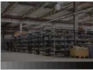 | ||||
| ·Brightness: Adjust the luminance of the screen image. | Press the ▲/▼button on the control panel or the √ button on the remote control to adjust the value. | 0 to 100 | ||
Original Setting High Setting Low Setting   | ||||
| ·Hue: Adjust the color balance of red and green. | Press the ▲/▼button on the control panel or the √ button on the remote control to adjust the value. | -50 to 50 | ||
ADJUSTING THE LCD DISPLAY
| Item Function Operation Range | |||
| Game or computer | • Game: Choose when viewing content from a connected game console.• Computer: Choose when a computer is connected through HDMI.Make sure that Format and edges > Picture format >Unscaled is selected so as to view maximum detail. | Press the ▲/▼button on the control panel or the √/button on the remote control to select the setting. | OffGameComputer |
| HDMI input range | Choose the output setting for the video input signal.Note: Select Limit when displaying the signal that uses 16-235 RGB levels. Otherwise select Full when displaying the signal that uses 0-235 RGB levels. | Press the ▲/▼button on the control panel or the √/button on the remote control to select the setting. | AutoLimitFull |
| Format and edges | • Picture format: Choose the picture format depending on the displayed content. | Press the ▲/▼button on the control panel or the √/button on the remote control to select the setting. | Auto zoomMovie expand 16:9Wide screenUnscaled4:3 |
| • Picture shift: Adjust the picture position. | Press the ▲/▼button on the control panel or the √/button on the remote control to adjust the setting. | N/A | |
| Input resolution | Choose the display resolution.Note: This option is available only if the input source is VGA. | Press the ▲/▼button on the control panel or the √/button on the remote control to select the setting. | 1366X768@601360X768@601280X768@601024X768@60 |
ADJUSTING THE LCD DISPLAY
5.2 Sound Settings
Picture
Sound
Tiling
General settings
Network settings
Sound style
Restore style
Bass
Treble
Balance
Surround mode
Audio out
Advanced
1 Press the MENU button on the control panel or the button on the remote control to call out the OSD window.
2 Select Sound, then press the INPUT button on the control panel or the OK button on the remote control.
3 Press the ▲/▼ button on the control panel or the ∥/ button on the remote control to select an option.
| Item Function Operation Range | |||
| Sound style | Choose the sound style for the audio content. | Press the ▲/▼button on the control panel or the 1/1 button on the remote control to select the setting. | Personal Original Movie Music Game News |
| Restore style | Restore the last-selected predefined sound setting. | Press the +/-button on the control panel or the -button on the remote control to select the setting. | Yes No |
| Bass | Adjust to increase or decrease lower-pitched sounds. | Press the ▲/▼button on the control panel or the 1/1 button on the remote control to adjust the value. | -8 to +8 |
| Treble | Adjust to increase or decrease higher-pitched sounds. | Press the ▲/▼button on the control panel or the 1/1 button on the remote control to adjust the value. | -8 to +8 |
| Balance | Adjust to emphasize left or right audio output balance. | Press the ▲/▼button on the control panel or the 1/1 button on the remote control to adjust the value. | -8 to +8 |
| Surround mode Enhance your audio experience. | Press the ▲/▼button on the control panel or the 1/1 button on the remote control to select the setting. | Off On | |
| Audio out Adjust audio output volume. | Press the ▲/▼button on the control panel or the 1/1 button on the remote control to adjust the value. | 0 to 60 | |
ADJUSTING THE LCD DISPLAY
| Item Function Operation Range | |||
| Advanced | • Auto volume leveling: Enable the reduction of sudden volume changes. | Press the ▲/▼button on the control panel or the 1/1button on the remote control to select the setting. | On Off |
| • Speaker settings: Turn on or off the internal speakers. | Press the ▲/▼button on the control panel or the 1/1button on the remote control to select the setting. | On Off | |
| • Clear sound: Enhance sound quality. | Press the ▲/▼button on the control panel or the 1/1button on the remote control to select the setting. | On Off | |
5.3 Tiling Settings

1 Press the MENU button on the control panel or the Button on the remote control to call out the OSD window.
2 Select Tiling, then press the INPUT button on the control panel or the OK button on the remote control.
3 Press the ▲▼button on the control panel or the √ button on the remote control to select an option.
| Item Function Operation Range | |||
| Enable | With this function, you can create a single large-screen matrix (video wall) that consists of up to 100 sets of this display (up to 10-sets on the vertical and 10-sets on the horizontal sides).If tiling is enabled, you can configure the following display settings:H monitorsV monitorsPositionFrame comp. | Press the ▲▼button on the control panel or the √ button on the remote control to select the setting. | OffOn |
| H monitors | Adjust displays on the horizontal side. | Press the ▲▼button on the control panel or the √ button on the remote control to adjust the value. | 0 to 10 |
| V monitors Adjust | displays on the vertical side. | Press the ▲▼button on the control panel or the √ button on the remote control to adjust the value. | 0 to 10 |
ADJUSTING THE LCD DISPLAY
| Item Function Operation Range | |||
| Position | Adjust the position of this display in the screen matrix. Please see the Example1 and Example2 for reference. | Press the ▲▼button on the control panel or the √∥button on the remote control to adjust the value. | 0 to 10 |
Example1: 2 x 2 screen matrix (4 displays)H monitors = 2 displaysV monitors = 2 displays Example2: 5 x 5 screen matrix (25 displays)H monitors = 5 displaysV monitors = 5 displays Example2: 5 x 5 screen matrix (25 displays)H monitors = 5 displaysV monitors = 5 displays | |||
| Frame comp. | If frame compensation is enabled, then the display will adjust the image to compensate for the width of the display bezels in order to accurately display the image. | Press the ▲▼button on the control panel or the √∥button on the remote control to select the setting. | OffOn |
ADJUSTING THE LCD DISPLAY
5.4 General Settings
| Picture | Menu language |
| Sound | Monitor ID |
| Tiling | Auto search |
| General settings | Clock |
| Network settings | Scheduling |
| Sleep timer | |
| EasyLink | |
| Local KB lock | |
| RC lock | |
| ANTI-BURN-IN | |
| Smart power |
1 Press the MENU button on the control panel or the button on the remote control to call out the OSD window.
2 Select General settings, then press the INPUT button on the control panel or the OK button on the remote control.
3 Press the /▲button on the control panel or the √ button on the remote control to select an option.
| Item Function Operation Range | |||
| Menu language | Choose the language used for OSD menus. | Press the ▲/▼button on the control panel or the √/button on the remote control to select the setting. | EnglishGermanTraditionalChineseFrenchItalianSpanishRussianPolishTurkishSimplifiedChinesePortugueseArabicJapanese |
| Monitor ID | Adjust the ID number for controlling the display via the RS232C connection. Each display must have a unique ID number when multiple sets of this display are connected. | Press the ▲/▼button on the control panel or the √/button on the remote control to adjust the value. | 1 to 255 |
| Auto search | Choose to let this display detect and display available signal sources automatically. | Press the ▲/▼button on the control panel or the √/button on the remote control to select the setting. | OffOnFailover |
ADJUSTING THE LCD DISPLAY
| Item Function Operation Range | |||
| Clock | Set the current date and time for the display's internal clock. | ||
| Daylight saving: Choose the daylight saving time. | Press the ▲/▼button on the control panel or the √/button on the remote control to select the setting. | Daylight saving time Standard time | |
| Date: Set current date. | Press the ▲/▼button on the control panel or the √/button on the remote control to set month, day, and year.Press the +/-button on the control panel or the ← button on the remote control to navigate between month, day, and year fields. | Cancel Done | |
| Time: Set current time. | Press the ▲/▼button on the control panel or the √/button on the remote control to set hours and minutes.Press the +/-button on the control panel or the ← button button on the remote control to navigate between hours and minutes fields. | Cancel Done | |
| Scheduling | This function allows you to program up to 7 different scheduled time intervals for this display to activate.You can set:Which input source the display will use for each scheduled activation period.The time for the display to turn on and turn off.The days in a week for the display to activate.Note:◆ We recommend you to set up current date and time in the Clock menu before using this function.◆ After changing the Clock option in the General settings menu, you need to set this Scheduling again. | ||
| Status: Enable or disable the schedule. | Press the ▲/▼button on the control panel or the √/button on the remote control to select the setting. | Off On | |
ADJUSTING THE LCD DISPLAY
| Item Function Operation Range | |||
| Scheduling (continued) | Source: Choose the source for the schedule. | Press the ▲/▼button on the control panel or the 1/1button on the remote control to select the setting. | USBHDMI 1HDMI 2Display portCard OPSDVI-DYPbPrAVVGA |
| On time: Set time when the schedule is turned on. | Press the ▲/▼button on the control panel or the 1/1button on the remote control to set hours and minutes.Press the +/-button on the control panel or the -/ button button on the remote control to navigate between hours and minutes fields. | CancelDone | |
| Off time: Set time when the schedule is turned off. | Press the ▲button on the control panel or the 1/1button on the remote control to set hours and minutes.Press the +/-button on the control panel or the -/ button button on the remote control to navigate between hours and minutes fields. | CancelDone | |
| Repeat modes: Choose the days in a week when the schedule is activated. | Press the ▲button on the control panel or the 1/1button on the remote control to select the item.Press the INPUT button on the control panel or the OK button on the remote control to confirm the selection. | No repeatEvery SundayEvery MondayEvery TuesdayEvery WednesdayEvery ThursdayEvery FridayEvery Saturday | |
ADJUSTING THE LCD DISPLAY
| Item Function Operation Range | |||
| Scheduling (continued) | Play setting: Choose the file to be included in the playlist.Note:♦ Each playlist supports up to 30 files.♦ Playlist will not be cleared afterFactory settings. You have to manually remove the files or deleteusb_schedulinglist.txton the USB disk drive. | ||
Press the ▲▼button on the control panel or the √ button on the remote control to choose the file.Press theINPUTbutton on the control panel or theOKbutton on the remote control to set or clear the playlist.Playlist View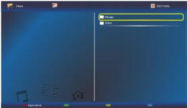 Press the — button on the remote control, then selectSave listto save the playlist.Press thebutton on the remote control to exit Playlist and return to the OSD menu.Save List Press the — button on the remote control, then selectSave listto save the playlist.Press thebutton on the remote control to exit Playlist and return to the OSD menu.Save List | |||
| Sleep timer | Switch off the display after a specified time. | Press the ▲▼button on the control panel or the √ button on the remote control to select the setting. | Off5 mins10 mins15 mins...240 mins |
| EasyLink | Connect and control your HDMI-CEC compliant devices through HDMI port to this display with the same remote control. | Press the ▲▼button on the control panel or the √ button on the remote control to select the setting. | OffOn |
ADJUSTING THE LCD DISPLAY
| Item Function Operation Range | |||
| Auto adjust | Use this function to automatically optimize the display of VGA input image.Note: This option is available only if the input source is VGA. | Press the +/- button on the control panel or the + button on the remote control to select the setting. | Cancel Start |
| Local KB lock | Choose to enable or disable the keyboard (control panel buttons) function of the LCD display.Unlock: Enable the keyboard function.Lock all: Lock all keyboard function.Lock but volume: Disable all the keyboard function except the + or -button.Lock but power: Disable all the keyboard function except the ⏻ button.Lock all expect volume and power: Disable all the keyboard function except the +, -,or ⏻ button.Note: To disable the Local KB lock function, press the ⚠ button and buttons 1 9 9 8 on the remote control. | Press the ▲▼ button on the control panel or the ∥ button on the remote control to select the setting. | UnlockLock allLock but volumeLock but powerLock all except volume and power |
ADJUSTING THE LCD DISPLAY
| Item Function Operation Range | |||
| RC lock | Choose to enable or disable the button function of the remote control. Unlock: Enable the button function of the remote control. Lock all: Lock all button functions of the remote control. Lock but volume: Disable all the button functions except the — or +button. Lock but power: Disable all the button functions except the ⏻ button. Lock all expect volume and power: Disable all the button functions of the remote control except the —, +or +button. Note: To disable the RC lock function, press the ⏱ button and buttons 1 9 9 8 on the remote control. | Press the ▲/▼button on the control panel or the √/button on the remote control to select the setting. | UnlockLock allLock but volumeLock but powerLock all except volume and power |
| ANTI-BURN-IN | For video input sources, enable ANTI-BURN-IN function to protect the display from “burn-in” or “after-image” symptoms when the display is not being in use for 30 seconds. | Press the ▲/▼button on the control panel or the √/button on the remote control to select the setting. | OffOn |
| Smart power | Choose a backlight level to optimise dynamic power consumption and picture contrast. | Press the ▲/▼button on the control panel or the √/button on the remote control to select the setting. | OffStandardBest PowerBest Picture |
| Wake on lan | Enable this feature to allow the display to be switched on over the network. | Press the ▲/▼button on the control panel or the √/button on the remote control to select the setting. | OffOn |
| Switch on state | Choose the display status used for the next time you connect the power cord. | Press the ▲/▼button on the control panel or the √/button on the remote control to select the setting. | OnStandbyLast status |
| LED | Set the display LED indicator on or off. | Press the ▲/▼button on the control panel or the √/button on the remote control to select the setting. | OffOn |
ADJUSTING THE LCD DISPLAY
| Item Function Operation Range | |||
| Switch on delay | Adjust the power-on delaying time (in seconds) allows a sequential powering-on for each display by their ID number when multiple displays are connected. | Press the ▲/▼button on the control panel or the √/button on the remote control to adjust the value. | 0 to 60 |
| Logo | When enabled, the AG Neovo logo will be shown on the startup screen. | Press the ▲/▼button on the control panel or the √/button on the remote control to select the setting. | Off On |
| APM | If APM function is enabled and no signal is detected, the LCD display will automatically turn off. | Press the ▲/▼button on the control panel or the √/button on the remote control to select the setting. | Off On |
| Information OSD | When this function is enabled and the display is turned on while in standby mode, an information OSD is displayed on the upper left corner of the screen. | Press the ▲/▼button on the control panel or the √/button on the remote control to select the setting. | Off On |
| DisplayPort Ver. | Set the DisplayPort version to 1.1a or 1.2. This setting is only valid on DisplayPort input and output as follows.1.1a: Switch DisplayPort Ver. to 1.1a(default), then the DisplayPort output is the clone of the DisplayPort input.1.2: Switch DisplayPort Ver. to 1.2 to support MST(Multi-Stream Transport).Note: If the display is black screen or abnormal under DisplayPort source, please switch to 1.1a and turn AC off and on. | Press the ▲/▼button on the control panel or the √/button on the remote control to select the setting. | 1.1a1.2 |
ADJUSTING THE LCD DISPLAY
| Item Function Operation Range | |||
| Cooling fan | Set the cooling fan operation.Off: Cooling fan is turned off.On: Cooling fan is turned on all the time during the LCD display is in operation.Auto: Cooling fan turns on when the LCD display temperature reaches 60°C (140°F).Note:A temperature warning message will appear on the screen when the temperature reaches 70°C (158°F).Regardless the cooling fan status off or on, the cooling fan is turned on automatically if the temperature reaches 70°C (158°F), for three successive minutes and a temperature-waning message is shown on the screen for 10 seconds. In this situation, the LCD display is shut down and the Power LED indicator will be blinking red and green. | Press the ▲▼button on the control panel or the √∥button on the remote control to select the setting. | OffOnAuto |
| Network control port | Choose the RS232 control from the Card OPS or embedded RS232 in the display. | Press the ▲▼button on the control panel or the √∥button on the remote control to select the setting. | RS232Card OPSRS232 |
| Factory settings | Reset all your customized settings to the factory defaults. | Press the + button on the control panel or the + button on the remote control to select the setting. | OKCancel |
ADJUSTING THE LCD DISPLAY
5.5 Network Settings
Picture
Sound
Tiling
General settings
Network settings
View network settings
Network configuration
Static IP configuration
Digital Media Render...
Network name
1 Press the MENU button on the control panel or the button on the remote control to call out the OSD window.
2 Select Network settings, then press the INPUT button on the control panel or the OK button on the remote control.
3 Press the ▲▼ button on the control panel or the √ button on the remote control to select an option.
| Item Function Operation Range | |||
| View network settings | View connected network status. | Press the INPUT button on the control panel or the OKiton on the remote control. | Close |
| Network configuration | Choose how the LCD display should assign addresses to the network resources. | Press the ▲/▼button on the control panel or the √/button on the remote control to select the setting. | DHCP & Auto IP Static IP |
| Static IP configuration | Configure the network parameters, such as IP address, netmask, gateway, DNS 1, and DNS 2.Note: This function can be only configured when the Network configuration setting is set to Static IP. | Press the ▲/▼button on the control panel or the √/button on the remote control to select the item. Then press the INPUT button on the control panel or the OKiton on the remote control to confirm the selection.Use the digit numbers [0] ~ [9] on the remote control to configure the network parameters.When the setting is complete, press the INPUT button on the control panel or the OK button. Press the + button on the control panel or the ← button on the remote control to select Done. Then press the INPUT button on the control panel or the OKiton on the remote control to save the setting. | IP address Netmask Gateway DNS 1 DNS 2 |
ADJUSTING THE LCD DISPLAY
| Item Function Operation Range | |||
| Digital Media Renderer - DMR | Enable this function to allow the display to receive multimedia files from the connected device from the network. | Press the ▲/▼button on the control panel or the √/button on the remote control to select the setting. | Off On |
| Network name | In the multiple-display connection, you can rename each display for easy identification. | Press the INPUT button on the control panel or the OK button on the remote control on the network name field to open the on-screen keyboard.Use the on-screen keyboard to enter the name. When done, select Done and press the INPUT button on the control panel or the OK button on the remote control.When the setting is complete, press the +/button on the control panel or the −button on the remote control to select Done. Then press the INPUT button on the control panel or the OKton on the remote control to save the setting. | N/A |
CHAPTER 6: APPENDIX
6.1 Warning Messages
| Warning Messages Cause Solution | ||
| [7Y6H] Cannot display this video mode | The resolution or the refresh rate of the graphics card of the computer is set too high. | · Change the resolution or the refresh rate of the graphics card. |
| [750K] No signal | The LCD display cannot detect the input source signal. | · Check if the input source is turned ON.· Check if the signal cable is properly connected.· Check if any pin inside the cable connector is twisted or broken. |
| [8C6Y] Local KB lock | The operation using the control panel buttons has been locked by the user. | · Disable the Local KB lock function. Refer to page 56. |
| [57AK] RC lock | The operation using the remote control buttons has been locked by the user. | · Disable the RC lock function. Refer to page 57. |
6.2 USB Device Compatibility
USB Video Subtitle Formats (for language subtitles, etc.).
| File Extensions | Container | Video codec | Maximum resolution | Max. Frame Rate (fps) | Max. Bit Rate (Mbps) | Audio codec |
| .mpgmpeg.vob | PS | MPEG-1 | 1920x1080 25p,30p,50i | ,60i 30 MPEG- | 1(L1&L2),MPEG-1,2,2.5 L3,AAC/HE-AAC(v1&v2),DVD-PCM,AC3 | |
| MPEG-2 | 1920x1080 25p,30p,50i | ,60i 30 | ||||
| MPEG-4ASP | 1920x1080 25p,30p,50i,60i 30 | |||||
| H.264 19 | 20x1080 25p,30p,50p | ,60p,60i 30 | ||||
| .ts TS | MPEG-2 | 1920x1080 25p,30p,50i | ,60i 30 | MPEG-1(L1&L2),MPEG-1,2,2.5 L3,AAC/HE-AAC(v1&v2),AC3,E-AC3,Dolby Pulse | ||
| MPEG-4ASP | 1920x1080 25p,30p,50i,60i 30 | |||||
| H.264 19 | 20x1080 25p,30p,50p | ,60p,60i 30 | ||||
| MVC | 1920x1080i@field rate=50, 60Hz1920x1080p@frame rate=24, 25,30Hz1280x720p@frame rate=50, 60Hz | -30 | ||||
| .ts.m2ts.mts.mt2 | MaTSTTS | MPEG-2 | 1920x1080 25p,30p,50i | ,60i 30 | MPEG-1(L1&L2),MPEG-1,2,2.5 L3,AAC/HE-AAC(v1&v2),AC3,E-AC3,Dolby Pulse | |
| MPEG-4ASP | 1920x10B0 25p,30p,50i,60i 30 | |||||
| H.264 19 | 20x1080 25p,30p,50p | ,60p,60i 30 | ||||
| MVC | 1920x1080i @ field rate=50, 60Hz1920x1080p @ frame rate=24, 25,30Hz1280x720p @ frame rate=50, 60Hz | -30 | ||||
| .ts.m2ts.mts | AVCHD | MPEG-2 | 1920x1080 25p,30p,50i | ,60i 30 MPEG- | 1(L1&L2),MPEG-1,2,2.5 L3,AAC/HE-AAC(v1&v2),AC3,E-AC3,Dolby Pulse | |
| MPEG-4ASP | 1920x1080 25p,30p,50i,60i 30 | |||||
| H.264 19 | 20X1080 25p,30p,50p | ,60p,60i 30 | ||||
APPENDIX
| File Extensions | Container | Video codec | Maximum resolution | Max. Frame Rate (fps) | Max. Bit Rate (Mbps) | Audio codec |
| .ts.m2ts.mts | AVCHD MVC | 1920x1080i@field rate=50, 60Hz1920x1080p@frame rate=24, 25,30Hz1280x720p @ frame rate=50, 60Hz | -30 | MPEG-1(L1&L2),MPEG-1,2,2.5 L3,AAC/HE-AAC (v1&v2),AC3,E-AC3,Dolby Pulse | ||
| .m4v M4V H.264 1920x1080 25p,30p,50p,60p,60i 30 AAC | ||||||
| .ism/Manifest.mpd | frag MP4 | H.264 1920x1080 25p,30p,50p,60p,60i 30 | AAC/HE-AAC(v1&v2),AC3,E-AC3,WMA,WMA-PRO | |||
| MVC | 1920x1080i@field rate=50, 60Hz1920x1080p@frame rate=24, 25,30Hz1280x720p @ frame rate=50, 60Hz | -30 | ||||
| .mp4 MP4 | MPEG-4 ASP | 1920x1080 25p,30p,50i,60i 30 | AAC/HE-AAC(v1&v2),AC3,E-AC3,WMA,WMA-PRO | |||
| H.264 1920x1080 30 | ||||||
| MVC | 1920x1080i@field rate=50, 60Hz1920x1080p@frame rate=24, 25,30Hz1280x720p @ frame rate=50, 60Hz | -30 | ||||
| WMV9/VC1 | 1920x1080 30p,60i 30 | |||||
| .mkv.mk3d | MKV | MPEG-4 ASP | 1920x1080 25p,30p,50i,60i 30 | MPEG-1(L1&L2),MPEG-1,2,2.5 L3,AAC/HE-AAC (v1&v2),AC3,E-AC3,WMA,WMA-PRO | ||
| H.264 1920x1080 30 | ||||||
APPENDIX
USB Multimedia Formats
| File Extensions | Container Video codec | Maximum resolution | Frequency (kHz) | Max. Bit Rate (Mbps) | Audio codec |
| .mp3 MP3 | - - 48 384 | MPEG-1,2,2.5 L3 | |||
| .wma.asf | WMA(V2 up to V9.2) | - - 48 192 WMA | |||
| .wma WMA Pro | - - 96 768 | WMA,WMA Pro | |||
| .wav(PC) LPCM | - - 192 768 LPCM | ||||
| .aif(mac).aiff(mac) | LPCM | - - 192 768 LPCM | |||
| .aac.mp4.m4a | AAC | - - 48 1024 | AAC,HE-AAC(v1&v2) | ||
| .pls.m3u | Playlists | - | - | - | |
| .m4a | M4A | - - 48 1024 | AAC,HE-AAC(v1&v2) |
Note:
Sound or video may not work if the contents have a standard bit rate/frame rate above the compatible Frame/sec listed in the table above.
- Video content with a Bit rate or Frame rate larger than the rate specified in the table above can cause choppy video during playback.
6.3 Supported Resolution
VGA Resolution:
| Standard Resolution | Active Resolution | Refresh Rate | Pixel Rate Aspect | Ratio Stand for Mode | ||
| H Pixels V | Lines | |||||
| VGA 640 | 480 | 60 Hz | 25.175 MHz | 4:3 Video | Graphic Array72 Hz 31.5 MHz | |
| 75 Hz | 31.5 MHz | |||||
| WVGA 720 | 400 70 Hz | 33.75 MHz | 16:9 | Wide Video Graphic Array | ||
| SVGA 800 | 600 | 60 Hz | 40 MHz | 4:3 Super VGA | ||
| 75 Hz | 49.5 MHz | |||||
| XGA | 1024 768 | 60 Hz | 65 MHz | 4:3 | Extended Graphic Array | |
| 75 Hz | 78.75 MHz | |||||
| WXGA | 1280 | 768 | 60 Hz | 79.5 MHz | 5:3 | Wide XGA |
| WXGA | 1280 | 800 | 60 Hz | 79.5 MHz | 16:10 | Wide XGA |
| SXGA | 1280 | 960 | 60 Hz | 108 MHz | 4:3 | Super XGA |
| SXGA | 1280 | 1024 | 60 Hz | 108 MHz | 5:4 | Super XGA |
| WXGA | 1360 | 768 | 60 Hz | 85.5 MHz | 16:9 | Wide XGA |
| WXGA | 1366 | 768 | 60 Hz | 85.5 MHz | 16:9 | Wide XGA |
| UXGA | 1600 | 1200 | 60 Hz | 162 MHz | 4:3 | Ultra XGA |
| HD1080 | 1920 | 1080 | 60 Hz | 148.5 MHz | 16:9 | HD1080 |
SDTV Resolution:
| Standard Resolution | Active Resolution | Refresh Rate | Pixel Rate Aspect | Ratio Stand for Mode | ||
| H Pixels V | Lines | |||||
| 480i | 720 480 | 29.97 Hz | 13.5 MHz | 4:3 | Modified NTSC Standard | |
| 480p | 59.94 Hz | 27 MHz | ||||
| 576i | 720 576 | 25 Hz | 13.5 MHz | 4:3 Modified PAL Standard | ||
| 576p | 50 Hz | 27 MHz | ||||
HDTV Resolution:
| Standard Resolution | Active Resolution | Refresh Rate | Pixel Rate Aspect | Ratio Stand for Mode | ||
| H Pixels V | Lines | |||||
| 720p 1280 | 720 | 50 Hz | 74.25 MHz | 16:9 | Normally DVB Mode | |
| 60 Hz | ||||||
| 1080i | 1920 | 1080 | 25 Hz | 74.25 MHz | 16:9 | Normally ATSC Mode |
| 30 Hz | ||||||
| 1080p | 1920 | 1080 | 50 Hz | 148.5 MHz | 16:9 | Normally ATSC Mode |
| 60 Hz | ||||||
APPENDIX
UHDTV Resolution:
| UHDTV Resolution | Active Resolution | Refresh Rate | Pixel Rate Aspect | Ratio Stand for Mode | |
| H Pixels V | Lines | ||||
| 3840 216 | 0 30 Hz 297 | MHz 16:9 Video wall application. | |||
Note:
UHD resolution is supported only on video wall arrays. Each individual LCD display supports a max resolution of 1080p.
General guidelines:
- The PC text quality is optimum in HD 1080 mode (1920 x 1080, 60Hz).
- Your PC display screen might appear different depending on the manufacturer (and your particular version of Windows).
- Check your PC instruction book for information about connecting your PC to a display.
- If a vertical and horizontal frequency-select mode exists, select 60Hz (vertical) and 31.5KHz (horizontal). In some cases, abnormal signals (such as stripes) might appear on the screen when the PC power is turned off (or if the PC is disconnected). If so, press the [INPUT] button to enter the video mode. Also, make sure that the PC is connected.
- When horizontal synchronous signals seem irregular in RGB mode, check PC power saving mode or cable connections.
- The display settings table complies to the IBM/VESA standards, and based on the analog input.
- The DVI support mode is regarded as same to the PC support mode.
- The best timing for the vertical frequency to each mode is 60Hz.
6.4 Cleaning
Caution When Using the Display
- Do not bring your hands, face or objects close to the ventilation holes of the display. The top of the display is usually very hot due to the high temperature of exhaust air being released through the ventilation holes. Burns or personal injuries may occur if any body parts are brought too close. Placing any object near the top of the display could also result in heat related damage to the object as well as the display itself.
- Be sure to disconnect all cables before moving the display. Moving the display with its cables attached may damage the cables and thus cause fire or electric shock.
- Disconnect the power plug from the wall outlet as a safety precaution before carrying out any type of cleaning or maintenance procedure.
Front Panel Cleaning Instructions
- The front of the display has been specially treated. Wipe the surface gently using only a cleaning cloth or a soft, lint-free cloth.
- If the surface becomes dirty, soak a soft, lint-free cloth in a mild detergent solution. Wring the cloth to remove excess liquid. Wipe the surface of the display to remove dirt. Then use a dry cloth of the same type to dry.
- Do not scratch or hit the surface of the panel with fingers or hard objects of any kind.
- Do not use volatile substances such as insert sprays, solvents and thinners.
APPENDIX
Cabinet Cleaning Instructions
- If the cabinet becomes dirty, wipe the cabinet with a soft, dry cloth.
- If the cabinet is extremely dirty, soak a lint-free cloth in a mild detergent solution. Wring the cloth to remove as much moisture as possible. Wipe the cabinet. Use another dry cloth to wipe over until the surface is dry.
- Do not allow any water or detergent to come into contact with the surface of the display. If water or moisture gets inside the unit, operating problems, electrical and shock hazards may result.
- Do not scratch or hit the cabinet with fingers or hard objects of any kind.
- Do not use volatile substances such as insert sprays, solvents and thinners on the cabinet.
- Do not place anything made from rubber or PVC near the cabinet for any extended periods of time.
6.5 Troubleshooting
| Symptom Possible Cause Remedy | ||
| No picture is displayed • The main power switch on the back of the display is not switched on.• The selected input has no connection.• The display is in standby mode. | 1 Plug in the power cord.2 Make sure the power switch is switched on.3 Connect a signal connection to the display. | |
| Interference displayed on the display or audible noise is heard | Caused by surrounding electrical appliances or fluorescent lights. | Move the display to another location to see is the interference is reduced. |
| Color is abnormal The signal cable is not connected properly. | Make sure that the signal cable is attached firmly to the back of the display. | |
| Picture is distorted with abnormal patterns | • The signal cable is not connected properly.• The input signal is beyond the capabilities of the display. | • Make sure that the signal cable is attached firmly.• Check the video signal source to see if it is beyond the range of the display. Please verify its specifications with this display's specification section. |
| Display image doesn't fill up the full size of the screen | The picture format is not set correctly. | Press the button and select Auto zoom. |
| Can hear sound, but no picture Improperly connected source signal cable. | Make sure that both video inputs and sound inputs are correctly connected. | |
| Can see picture but no sound is heard | • Improperly connected source signal cable.• Volume is turned all the way down.• MUTE function is turned on.• No external speaker connected. | • Make sure that both video and sound inputs are correctly connected.• Press the +or -button to hear the sound.• Switch the MUTE function off by using the × button.• Connect the external speakers and adjust the volume to a suitable level. |
| Some picture elements do not light up | Some pixels of the display may not turn on. | This display is manufactured using an extremely high level of precision technology: however, sometimes some pixels of the display may not display. This is not a malfunction. |
| After-Images can still be seen on the display after the display is powered off. (Examples of still pictures include logos, video games, computer images, and images displayed in 4:3 normal mode) | A still picture is displayed for an over extended period of time. | Do not allow a still image to be displayed for an extended period of time as this can cause a permanent after-image to remain on the display. |
APPENDIX
6.6 Transporting the LCD Display
To transport the LCD display for repair or shipment, place the display in its original packaging carton.
1 Put all the accessories in the box (if necessary).
2 Place the lower foam cushion inside the lower box (a).
3 Place the LCD display down in the lower box.
4 Place the upper foam cushion on top of the LCD display.
5 Place the accessories box on the designated area (if necessary).
6 Place the upper box (b) on LCD display.
7 Secure the upper box to the lower box with the supplied locks (c).

CHAPTER 7: SPECIFICATIONS
7.1 Display Specifications
| Display PD-42 PD-49 PD-55 | |||
| Screen Size (Active Area) | 41.92" (106.47 cm) LCD | 48.50" (123.2 cm) LCD | 54.64" (138.78 cm) LCD |
| Aspect Ratio 16:9 | |||
| Number of Pixels 1920 (H) x | 1080 (V) | ||
| Pixel Pitch 0.4833 (H) x 0.48 | 33 (V)[mm] | 0.55926 (H) x 0.55926(V) [mm] | 0.630 (H) x 0.630 (V)[mm] |
| Displayable Colors 10bits(D), 1.07 Billion colors | |||
| Brightness (Typical) 700 cd/m2 | m2 (DS424PMB)500 cd/m2 (DS424PMC) | 700 cd/m2 (DS494PMB)500 cd/m2 (DS494PMC) | 700 cd/m2 (DS554PMB)500 cd/m2 (DS554PMC) |
| Contrast Ratio (Typical) 1300:1 | |||
| Viewing Angle 178 degrees | |||
| In/Out Terminals PD-42 PD-49 PD-55 | ||||
| Speaker Output Internal SpeakersExternal Speakers | 10W (L) + 10W (R) [RMS]/8Ω1 Way 1 Speaker System82 dB/W/M/160 Hz ~ 13 KHz | |||
| Audio Output | 3.5mm phone jack x 1 | 0.5V [rms] (Normal) / 2 Channel (L+R) | ||
| Audio Input | RCA Jack x 23.5mm phone jack x 1 | 0.5V [rms] (Normal) / 2 Channel (L+R) | ||
| RS232C | 2.5mm Phone jack x 2 | RS232C in/RS232C out | ||
| RJ-45 | RJ-45 Jack x 1 (8 pin) | 10/100 LAN Port | ||
| HDMI Input | HDMI Jack x 2(Type A) (19 pin) | Digital RGB: TMDS (Video + Audio)MAX: Video - 720p, 1080p, 1920 x 1080/60 Hz (WUXGA)Audio - 48 KHz/ 2 Channel (L+R)Supports LPCM only | ||
| DVI-D Input | DVI-D jack | Digital RGB: TMDS (Video) | ||
| VGA Input | D-Sub Jack x 1 (15 pin) | Analog RGB: 0.7V [p-p] (75Ω), H/CS/V: TTL (2.2kΩ), SOG: 1V [p-p] (75Ω)MAX: 720p, 1080p, 1920 x 1080/60 Hz (WUXGA) | ||
| DVI-I (DVI-D & VGA) Output | DVI-I Jack x 1 (29 pin) | Digital RGB: TMDS (Video)Analog RGB: 0.7V [p-p] (75Ω), H/CS/V: TTL (2.2kΩ), SOG: 1V [p-p] (75Ω)MAX: 720p, 1080p, 1920 x 1080/60 Hz (WUXGA) | ||
| Component Input | BNC Jack x 3 | Y: 1V [p-p] (75Ω), Pb: 0.7V [p-p] (75Ω), Pr: 0.7V [p-p] (75Ω)MAX: 480i, 576i, 480p, 576p, 720p, 1080i, 1080p | ||
| Video Input | BNC x 1 (Share with Component_Y) | Composite 1V [p-p] (75Ω) | ||
| Displayport in/out | Displayport Jack x 2(20 pin) | Digital RGB: TMDS (Video + Audio)MAX: Video - 720p, 1080p, 1920 x 1080/60 Hz (WUXGA)Audio - 48 KHz/ 2 Channel (L+R)Supports LPCM only | ||
| IR Input | 3.5mm stereo x 1 | External IR input | ||
| IR Output | 3.5mm stereo x 1 | External IR output | ||
SPECIFICATIONS
| General PD-42 PD-49 PD-55 | |||
| Power Supply AC 100 - 240V, 50 - 60Hz | |||
| Power Consumption (Max.) 240 W 240 W 265 W | |||
| Power Consumption (Typ.) 120 W 120 W 145 W | |||
| Power Consumption (Standby & Off) <0.5 W (RS232 in active) | |||
| Dimensions [W x H x D] 946.94 x 540 | 96 x71.1(@Handle) /56.8(@Wall Mount)mm | 1092.78 x 623.0 x71.1(@Handle) /56.8(@Wall Mount)mm | 1228.6 x 699.4 x71.1(@Handle) /56.8(@Wall Mount)mm |
| Weight 15.3 Kg 19.0 Kg 24.7 Kg | |||
| Gross Weight 19.5 Kg 24.9 Kg 31.1 Kg | |||
| Environmental Condition PD-42 PD-49 PD-55 | ||||
| Temperature | Operational | 0 ~ 40°C | ||
| Storage | -20 ~ 60°C | |||
| Humidity | Operational | 20 ~ 80% RH (No condensation) | ||
| Storage | 5 ~ 95% RH (No condensation) | |||
| Altitude | Operational | 0 ~ 3,000 m | ||
| Storage / Shipment | 0 ~ 9,000 m | |||
| Internal Speaker | PD-42 PD-49 PD-55 | |
| Type | 1 Way 1 Speaker | |
| Input | 10 W (RMS) | |
| Impedance | 8Ω | |
| Output Sound Pressure | 82 dB/W/M | |
| Frequency Response | 160 Hz ~ 13 KHz | |
Note:
All specifications are subject to change without prior notice.
SPECIFICATIONS
7.2 Display Dimensions
7.2.1 PD-42 Dimensions
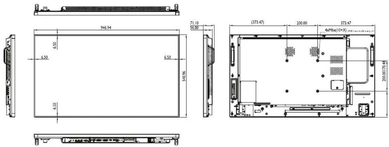
7.2.2 PD-49 Dimensions

7.2.3 PD-55 Dimensions
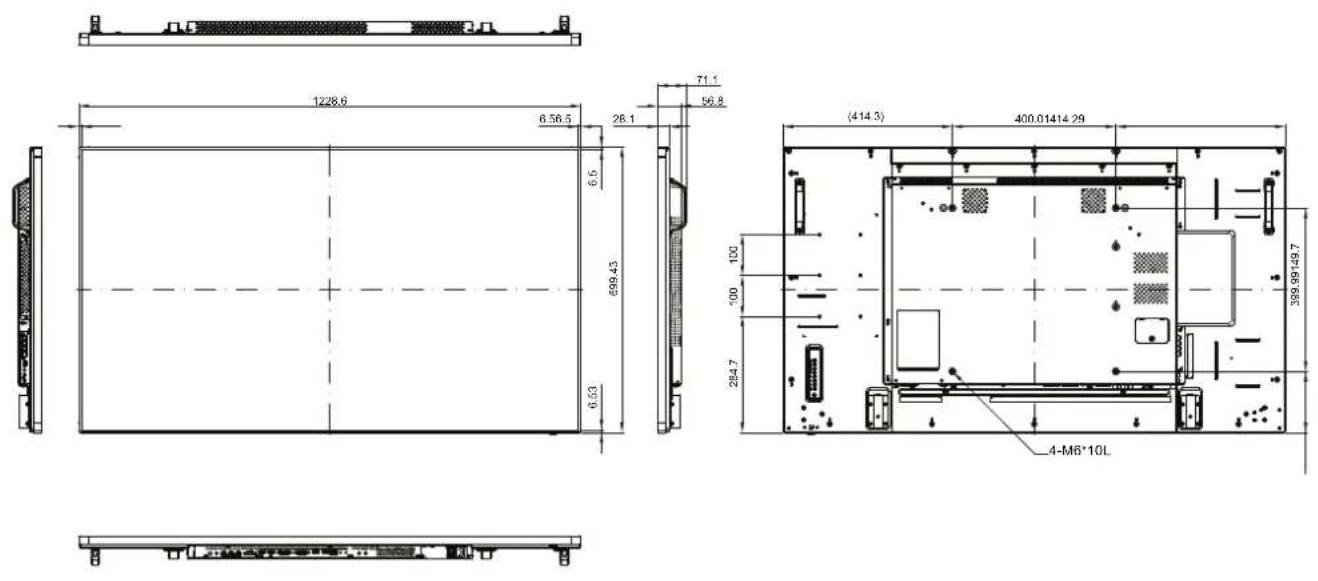

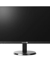
- SAFETY INFORMATION .... 1
- PRECAUTIONS 8
- CHAPTER 1: PRODUCT DESCRIPTION.... 11
- CHAPTER 2: MAKING CONNECTIONS....24
- TABLE OF CONTENTS
- CHAPTER 3: USING THE LCD DISPLAY....34
- CHAPTER 4: ON SCREEN DISPLAY MENU....45
- CHAPTER 5: ADJUSTING THE LCD DISPLAY 49
- CHAPTER 6: APPENDIX....66
- CHAPTER 7: SPECIFICATIONS....75
- Federal Communications Commission (FCC) Notice (U.S. Only)
- SAFETY INFORMATION
- CE Declaration of Conformity
- Polish Center for Testing and Certification Notice
- Electric, Magnetic and Electromagnetic Fields ("EMF")
- Information for U.K. only
- How to connect a plug
- North Europe (Nordic Countries) Information
- End-of-Life Disposal
- (For customers in Canada and U.S.A.)
- Waste Electrical and Electronie Equipment-WEEE
- Attention users in European Union private households
- Attention users in United States:
- End of Life Directives-Recycling
- Restriction on Hazardous Substances statement (India)
- E-Waste Declaration for India
- Batteries
- Turkey RoHS
- Notice
- Cautions When Setting Up
- Cautions When Using
- Cleaning and Maintenance
- Warning:
- Notice for the LCD Display
- CHAPTER 1: PRODUCT DESCRIPTION
- Package Contents
- Note:
- PRODUCT DESCRIPTION
- Preparing for the Installation
- Installing and Removing Table Stands (optional)
- Wall Mounting Installation
- VESA Grid
- Caution:
- Ventilation Requirements for Enclosure Locating
- Mounting in Portrait Position
- Using the Remote Sensor and Power Status Indicator
- LCD Display Overview
- [+] Power
- MUTE
- INPUT
- [+] Increase
- [—] Decrease
- [▲] Up
- [▼] Down
- MENU
- Remote control sensor and power status indicator
- Input/Output Terminals
- AC IN
- Main power switch
- IR IN/IR OUT
- RS232C IN/ RS232C OUT
- RJ-45
- HDMI1 IN/ HDMI2 IN
- DVI IN
- DVI OUT
- DisplayPort IN/ DisplayPort OUT
- VGA IN (D-Sub)
- COMPONENT IN (BNC)
- Y/CVBS
- PC Audio In
- SPEAKER SWITCH
- SECURITY LOCK
- AUDIO IN
- AUDIO OUT
- USB(F/W)
- SPEAKERS
- OPS SLOT
- Remote Control
- General Functions
- POWER
- PLAY
- [SOURCE]
- [↑HOME]
- [LIST
- [1] [7] [+] [ ]-NAVIGATION buttons
- [∅QK
- [↑]ADJUST
- [1]MUTE
- [][][][] COLOR
- [Number/ ID SET/ ENTER]
- FORMAT
- [←] BACK
- [ ]iNFO
- OPTIONS
- [一][+]VOLUME
- ID Remote Control
- Inserting the Batteries in the Remote Control
- Handling the Remote Control
- Operating Range of the Remote Control
- CHAPTER 2: MAKING CONNECTIONS
- Connecting the Power
- MAKING CONNECTIONS
- Connecting a Computer
- Using VGA Input
- Using DVI Input
- Using HDMI Input
- Using DisplayPort Input
- Connecting External Equipment (DVD / DVD-B)
- Using COMPONENT Video Input
- Using Video Source Input
- Using HDMI Video Input
- Connecting Audio Equipment
- Connecting External Speakers
- Connecting an External Audio Device
- Connecting Multiple Displays in a Daisy-chain Configuration
- Display Control Connection
- Digital Video Connection
- Analog Video Connection
- IR Connection
- IR Pass-Through Connection
- Connecting to Wired Network
- To setup the network:
- CHAPTER 3: USING THE LCD DISPLAY
- Turning on the Power
- Selecting the Input Source Signal
- USING THE LCD DISPLAY
- Adjusting the Volume
- Changing the Picture Format
- Choosing Your Preferred Picture Settings
- Choosing Your Preferred Sound Settings
- Playing Multimedia Files via Local Area Network
- Set Up the Network
- Set Up Media Sharing
- How to Use DLNA-DMP
- Play Files from Display
- How to Use DLNA-DMR from PC
- Play Files
- Tips:
- Playing Multimedia Files from USB Device
- Play Options
- Playing Music Files
- Music options
- Playing Movie Files
- Movie options
- Playing Photo Files
- Start a Slideshow
- Slideshow options
- CHAPTER 4: ON SCREEN DISPLAY MENU
- Using the OSD Menu
- ON SCREEN DISPLAY MENU
- OSD Menu Tree
- Picture
- CHAPTER 5: ADJUSTING THE LCD DISPLAY
- Picture Settings
- ADJUSTING THE LCD DISPLAY
- Sound Settings
- Sound
- Tiling Settings
- General Settings
- Network Settings
- CHAPTER 6: APPENDIX
- Warning Messages
- USB Device Compatibility
- APPENDIX
- Supported Resolution
- General guidelines:
- Cleaning
- Caution When Using the Display
- Front Panel Cleaning Instructions
- Cabinet Cleaning Instructions
- Troubleshooting
- Transporting the LCD Display
- CHAPTER 7: SPECIFICATIONS
- Display Specifications
- SPECIFICATIONS
- Display Dimensions
- PD-42 Dimensions
- PD-49 Dimensions
Brand : AG Neovo
Model : PD-55
Category : Screen