
CA-HM-GM.003 - Electronics PIONEER - Free user manual and instructions
Find the device manual for free CA-HM-GM.003 PIONEER in PDF.


| Product Type | Stereo Receiver / Amplifier |
| Brand | Pioneer |
| Model | CA-HM-GM.003 |
| Dimensions (W x H x D) | 435 x 148 x 385 mm (approx.) |
| Weight | 8.5 kg (approx.) |
| Power Supply | AC 120V / 60Hz |
| Power Output | 100W per channel (8 ohms, 20Hz-20kHz, 0.05% THD) |
| Frequency Response | 5 Hz - 100 kHz (+0/-3 dB) |
| Inputs | 4x RCA audio, 2x optical, 1x coaxial, USB, Phono (MM) |
| Outputs | Speaker terminals (A/B), Pre-out, Subwoofer out, Headphone jack |
| Main Functions | AM/FM tuner, Bluetooth, Wi-Fi, multi-room audio, tone controls, loudness |
| Remote Control | Included (IR) |
| Display | Fluorescent dot matrix display with adjustable brightness |
| Cleaning | Wipe with dry soft cloth; avoid solvents or abrasive cleaners |
| Safety | Do not expose to moisture; ensure proper ventilation; disconnect during storms |
| Spare Parts / Repairability | Available through authorized service centers; refer to manual for part numbers |
| General Information | Designed for home audio systems; compatible with 4-16 ohm speakers; includes automatic standby |
Frequently Asked Questions - CA-HM-GM.003 PIONEER
User questions about CA-HM-GM.003 PIONEER
0 question about this device. Answer the ones you know or ask your own.
Ask a new question about this device
Download the instructions for your Electronics in PDF format for free! Find your manual CA-HM-GM.003 - PIONEER and take your electronic device back in hand. On this page are published all the documents necessary for the use of your device. CA-HM-GM.003 by PIONEER.
USER MANUAL CA-HM-GM.003 PIONEER
INSTALLATION INSTRUCTIONS FOR PART 99-3309B
APPLICATIONS
Chevrolet Spark 2013-up 99-3309B
KIT FEATURES
• ISO DIN head unit provision with pocket
• DDIN head unit provisions
- Interface included retains factory OnStar, Bluetooth, and all warning chimes
- Provides a 12-volt accessory power and VSS, parking brake, and reverse signals
- Painted Matte Black

natural_image
Interior view of a car dashboard and steering wheel (no visible text or symbols)KIT COMPONENTS
• A) Radio Trim Panel • B) Radio Brackets • C) Pocket • D) (4) #8 x 3/8" Phillips screws • E) (10) White Plastic Panel Clips
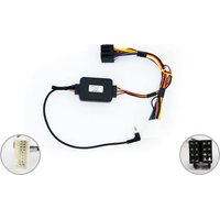
• F) Interface • G) 16-pin harness • H) 4-pin to 4-pin resistor pad • I) 22-pin to 44-pin harness

WIRING & ANTENNA CONNECTIONS (sold separately)
Wiring Harness: • Interface included Antenna Adapter: • 40-EU55 antenna adapter
Table of Contents
Dash Disassembly
- Chevy Spark 2013-up .... 2
Kit Assembly
- ISO radio provision with pocket 3
- DDIN radio provision 4
Axxess Interface Installation
- Installing Interface....5-6
- Vehicle Customization with Optional LCD....7
TOOLS REQUIRED
- Panel removal tool • Phillips screwdriver
- Small flat-blade screwdriver
CAUTION: Metra recommends disconnecting the negative battery terminal before beginning any installation. All accessories, switches, and especially air bag indicator lights must be plugged in before reconnecting the battery or cycling the ignition.
NOTE: Refer to the instructions included with the aftermarket radio.

99-33098
Dash Disassembly
- Unclip and remove the radio trim panel. (Figure A)
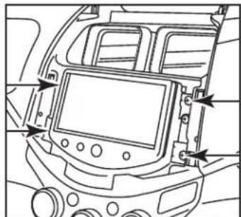
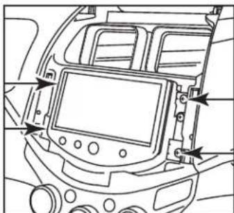
- Remove (4) Phillips screws securing the factory radio and remove from dash. (Figure B)
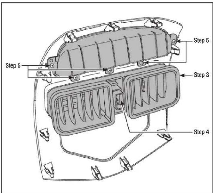
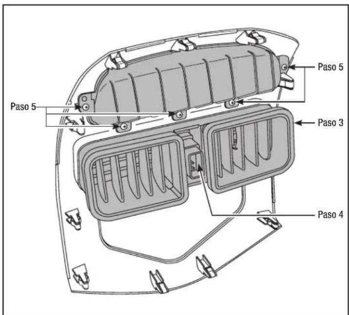
- Unclip and remove the vents from the factory panel. (Figure C)
- Unclip and remove the hazard button from the trim panel. (Figure C)
- Remove (5) Phillips screws securing the upper display shroud from the factory panel. (Figure C) Continue to kit assembly

natural_image
Line drawing of a car dashboard with control panels and buttons (no text or symbols)(Figure A)
natural_image
Line drawing of a car dashboard with no visible text or symbols(Figure B)
(Figure C)

99-33098
Kit Assembly
ISO DIN radio provisions
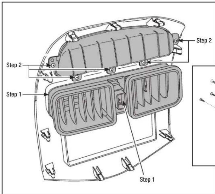
- Attach the factory vents and hazard button to the Metra trim panel. (Figure A)
- Attach the upper display shroud the Metra trim panel with the factory screws. (Figure A)
- Attach the provided (10) panel clips to the legs of the Metra trim panel.
- Locate the factory wiring harness in the dash. Metra recommends using the proper mating adapter from Metra or AXXESS. Re-connect the negative battery terminal and test the unit for proper operation.
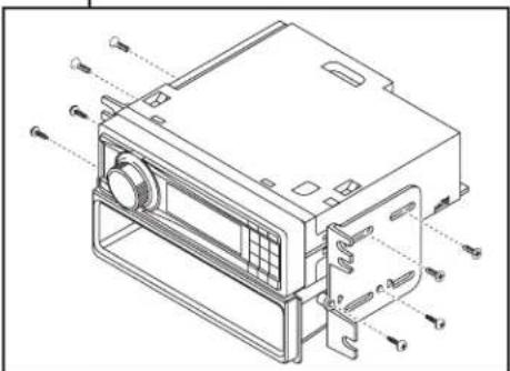
- Attach the radio brackets to the aftermarket radio using the screws supplied with the radio, then secure the assembly to the pocket using the (4) #8 x 3/8" Phillips screws. (Figure B)
- Mount the assembly into the sub-dash.
- Reassemble dash in reverse order of disassembly using the Metra trim panel instead of the factory trim panel.
(Figure B)
(Figure A)

99-33098
Kit Assembly
DDIN radio provisions
- Attach the factory vents and hazard button to the Metra trim panel. (Figure A)
- Attach the upper display shroud the Metra trim panel with the factory screws. (Figure A)
- Attach the provided (10) panel clips to the legs of the Metra trim panel.
- Locate the factory wiring harness in the dash. Metra recommends using the proper mating adapter from Metra or AXXESS. Re-connect the negative battery terminal and test the unit for proper operation.
- Attach the radio brackets to the aftermarket radio using the screws supplied with the radio, then mount the assembly into the sub dash. (Figure B)
- Reassemble dash in reverse order of disassembly using the Metra trim panel instead of the factory trim panel.


natural_image
Technical line drawing of an electronic device with ports and connectors (no text or symbols)(Figure B)
(Figure A)

99-3309B
Axxess Interface Installation
FEATURES
- Provides accessory (12-volt 10-amp)
• Retains R.A.P. (Retained Accessory Power)
• Used in amplified or non-amplified systems
• Retains all warning chimes - Provides NAV outputs (parking brake, reverse, mute, and V.S.S.)
• Retains OnStar/OE Bluetooth - Adjustable volume for chimes and OnStar
• High level speaker input - Micro "B" USB updatable
• Retains balance and fade
INTERFACE COMPONENTS
- 4-pin to 4-pin resistor pad harness • 16-pin with stripped leads • 22-pin to 44-pin Camaro Harness
• 18-pin to 10-pin HVAC Harness
TOOLS REQUIRED
- Cutting tool • Crimping tool • Tape • Connectors (butt-connectors, bell caps, etc.)
Installing the Interface
From the 16-pin harness:
- Connect the Red wires to the ignition/accessory wire of the aftermarket radio
- Connect the Orange/White wire to the illumination wire of the aftermarket radio. If the aftermarket radio has no illumination wire, tape off the Orange/White wire.
- Connect the Blue/White wire to the amp turn on wire of the aftermarket radio.
- Connect the Brown wire to the mute wire of the aftermarket radio. If the aftermarket radio does not have a Mute wire, tape up the Brown wire.
- Connect the White wire to the left front positive speaker output of the aftermarket radio
- Connect the White/Black wire to the left front negative speaker output of the aftermarket radio
- Connect the Gray wire to the right front positive speaker output of the aftermarket radio
- Connect the Gray/Black wire to the right front negative speaker output of the aftermarket radio
• The Violet wire is not used in the application - The Violet/Black wire is not used in the application
-
The Green wire is not used in the application
-
The Green/Black wire is not used in this application.
The following wires are for the aftermarket radios that have navigation built in: - Connect the Light Green wire to the parking brake wire of the aftermarket navigation radio.
- Connect the Blue/Pink wire to the VSS or speed sense wire of the aftermarket navigation radio.
- Connect the Green/Purple wire to the reverse wire of the aftermarket navigation radio.
From the 44-way harness:
- Connect the Black wire to the ground wire of the aftermarket radio.
- Connect the RCA's to the AUX in on the aftermarket radio (if equipped).
Note: This will allow you to retain the 3.5 AUX JACK in the console. - Connect the Yellow wire to the 12-volt constant wire of the aftermarket radio.
- If the vehicle is amplified disconnect the 4-pin harness located between the 44-way and 22-way connector and connect the supplied 4-pin to 4-pin resistor pad.

99-3309B
Installing the Interface
Amplified vehicles:
- Connect the Violet wire to the right rear positive wire of the aftermarket radio
- Connect the Violet/Black wire to the right rear negative wire of the aftermarket radio
- Connect the Green wire to the left rear positive wire of the aftermarket radio
- Connect the Green/Black wire to the left rear negative wire of the aftermarket radio
Non-amplified vehicles:
- Cut the resistors from the Green, Green/black, Purple, Purple/Black right below the heat shrink
- Connect the Violet wire to the right rear positive wire of the aftermarket radio
- Connect the Violet/Black wire to the right rear negative wire of the aftermarket radio
- Connect the Green wire to the left rear positive wire of the aftermarket radio
- Connect the Green/Black wire to the left rear negative wire of the aftermarket radio
The Pink wire is not used in this application.
Installing the Interface:
- With all the connections completed, plug the 16 and 22 pin harnesses into the interface.
- Plug the 44 pin GM harness into the vehicle side harness, and plug the aftermarket radio harness into the aftermarket radio.
- Reconnect the negative battery terminal.
Chime Volume Adjustment
1) With car on, shut off car and leave keys in ignition. Open the car door and leave it open. Chimes will be heard.
2) Wait 10 seconds, then with a small screwdriver adjust the potentiometer fully counterclockwise (all the way left), then clockwise to raise chime level and counterclockwise to lower the chime level.
3) When the volume is at the desired level, remove the keys from the ignition. This will lock the chime volume at its current level.
Audio Level Adjustment
1) Start your vehicle and turn on the radio having audio playing.
2) Turn your aftermarket radio's volume up 34 of the way.
3) With a small screwdriver adjust the potentiometer clockwise to raise the audio level and counterclockwise to lower the audio level.
4) Once at desired level your audio adjustment is complete.
OnStar Level Adjustment
To adjust the OnStar volume level find the Black/Yellow wire on the 16-pin harness. Push the blue OnStar button, while the voice is speaking tap the Black/Yellow wire to ground. Once the volume is set it will stay at that volume until the Black/Yellow wire is tapped to ground again. This can be set during installation and then left alone. If user adjustment is desired, the customer may also tap "Volume Up" or down on the steering wheel (if equipped) to adjust the OnStar level.
Additional 12-pin harness (ASWC-1)
- This 12-pin harness is to be used in conjunction with the ASWC-1 (not included). Please refer to the ASWC-1 instructions for programming.

99-3309B
Vehicle customization with optional LCD
(AXXESS part # XIA-LCD sold separately)
Notes
The OEM radio is used to customize certain features of the vehicle.
Use the optional LCD to adjust these features accordingly:
- Press the "ESC" button and "Press Enter to Set Language" will appear on the screen.
- To change the "Language" press the "Enter" button then press then press the UP and "Down" buttons to change the "Language".
- Once you have chosen your "Language" then press "ESC" to go back to be able to scroll through the other settings.
- If you do not wish to change the "Language" you can scroll up and down through the different settings with the "Up" and "Down" buttons.
- Remember to press "Enter" to change the desired setting.

INSTALLATION INSTRUCTIONS FOR PART 99-3309B

KNOWLEDGE IS POWER
Enhance your installation and fabrication skills by enrolling in the most recognized and respected.
enrolling in the most recognized and resp. mobile electronics school in our industry.
Log onto www.installerinstitute.com or call
800-354-6782 for more information and take steps toward a better tomorrow.

Metra recommends MECP
certified technicians

natural_image
Interior view of a car dashboard and steering wheel (no visible text or symbols)COMPONENTES DEL KIT
natural_image
Technical line drawings of various electronic components and connectors, including a BCDE package, connector box, screw screws, and connector terminals (no text or symbols present)natural_image
Interior view of a car dashboard and air intake manifold (no text or symbols visible)(Figura A)
natural_image
Technical line drawing of a car dashboard with no visible text or symbols(Figura B)
(Figura C)

99-3309B
Ensamble del kit
natural_image
Technical line drawing of a device chassis with mounting holes and internal components (no text or symbols)(Figura B)
(Figura A)

99-3309B
- INSTALLATION INSTRUCTIONS FOR PART 99-3309B
- Chevrolet Spark 2013-up 99-3309B
- KIT FEATURES
- KIT COMPONENTS
- Table of Contents
- Dash Disassembly
- Kit Assembly
- Axxess Interface Installation
- TOOLS REQUIRED
- ISO DIN radio provisions
- DDIN radio provisions
- FEATURES
- INTERFACE COMPONENTS
- Installing the Interface
- From the 16-pin harness:
- From the 44-way harness:
- Amplified vehicles:
- Non-amplified vehicles:
- Installing the Interface:
- Chime Volume Adjustment
- Audio Level Adjustment
- OnStar Level Adjustment
- Additional 12-pin harness (ASWC-1)
- Vehicle customization with optional LCD
- Notes
- The OEM radio is used to customize certain features of the vehicle.
- COMPONENTES DEL KIT
- Ensamble del kit
Brand : PIONEER
Model : CA-HM-GM.003
Category : Electronics