
EPF09V1K8 - Air conditioner ELECTROLUX - Free user manual and instructions
Find the device manual for free EPF09V1K8 ELECTROLUX in PDF.


| Product Type | Split Air Conditioner |
| Model | EPF09V1K8 |
| Brand | Electrolux |
| Cooling Capacity | 9000 BTU/h |
| Heating Capacity | 9000 BTU/h (Heat Pump) |
| Power Input (Cooling) | 900 W |
| Power Input (Heating) | 900 W |
| Energy Efficiency (SEER) | 15.0 |
| Refrigerant | R32 |
| Indoor Unit Dimensions (WxHxD) | 800 x 300 x 200 mm |
| Outdoor Unit Dimensions (WxHxD) | 700 x 500 x 250 mm |
| Indoor Unit Weight | 10 kg |
| Outdoor Unit Weight | 30 kg |
| Indoor Noise Level (Low/High) | 30 / 40 dB(A) |
| Outdoor Noise Level | 55 dB(A) |
| Power Supply | 220-240 V, 50 Hz |
| Operating Temperature (Cooling) | 16°C - 32°C |
| Operating Temperature (Heating) | -5°C - 24°C |
| Filter Type | Washable Mesh Filter |
| Functions | Remote Control, Timer, Sleep Mode, 4 Fan Speeds, Swing, Auto Restart, Self Cleaning |
| Installation Type | Wall Mounted |
| Warranty | 5 Years (Compressor), 2 Years (Parts) |
Frequently Asked Questions - EPF09V1K8 ELECTROLUX
User questions about EPF09V1K8 ELECTROLUX
0 question about this device. Answer the ones you know or ask your own.
Ask a new question about this device
Download the instructions for your Air conditioner in PDF format for free! Find your manual EPF09V1K8 - ELECTROLUX and take your electronic device back in hand. On this page are published all the documents necessary for the use of your device. EPF09V1K8 by ELECTROLUX.
USER MANUAL EPF09V1K8 ELECTROLUX
- SAFETY INSTRUCTIONS....3
- INDOOR UNIT PARTS AND MAJOR FUNCTIONS......5
- MANUAL OPERATIONS....16
- CARE AND MAINTENANCE....17
- TROUBLESHOOTING 19
- EUROPEAN DISPOSAL GUIDELINES 23
WE'RE THINKING OF YOU
Thank you for purchasing an Electrolux appliance. You've chosen a product that brings with it decades of professional experience and innovation. Ingenious and stylish, it has been designed with you in mind. So whenever you use it, you can be safe in the knowledge that you'll get great results every time. Welcome to Electrolux.
Visit our website to:

Get usage advice, brochures, trouble shooter, service information:
www.electrolux.com

Register your product for better service:
www.electrolux.com/productregistration

Buy Accessories, Consumables and Original spare parts for your appliance:
www.electrolux.com/shop
CUSTOMER CARE AND SERVICE
We recommend the use of original spare parts.
When contacting Service, ensure that you have the following data available.
The information can be found on the rating plate. Model, PNC, Serial Number

Warning / Caution-Safety information.

General information and tips.

Environmental information.
Subject to change without notice.
1. ⚠ SAFETY INSTRUCTIONS
Before the installation and use of the appliance, carefully read the supplied instructions. The manufacturer is not responsible if an incorrect installation and use causes injuries and damages. Always keep the instructions with the appliance for future reference.
1.1 Children and vulnerable people safety

WARNING!
Risk of suffocation, injury or permanent disability.
- This appliance can be used by children aged from 8 years and above and persons with reduced physical, sensory or mental capabilities or lack of experience and knowledge if they have been given supervision or instruction concerning use of the appliance in a safe way and understand the hazards involved.
• Children shall not play with the appliance. - Cleaning and user maintenance shall not be made by children without supervision.
1.2 Installation and Use

WARNING!
Risk of suffocation, injury or permanent disability.
- Contact an authorised installer for installation of this unit.
- Contact an authorised service technician for repair or maintenance of this unit.
- The socket outlet required to supply power must be connected and commissioned by a licenced contractor.
- If the supply cord is damaged, it must be replaced by the manufacturer, its service agent or similarly qualified persons in order to avoid a hazard.
• Installation work must be performed in accordance with the national wiring
standards and the electricity suppliers service rules by authorised personnel only.
- If the unit is to be moved to another location or disposed of, only a suitably qualified person is permitted to undertake such work.
- If you notice an unusual situation, such as a burning smell, please switch off the power to the air conditioner and contact an Electrolux service agent. If this abnormal status continues the air conditioner may be damaged or even cause electric shock or fire.
- Do not operate the air conditioner with wet hands. This may cause electric shock.
- Do not damage or cut off the power cord or other wires. If this occurs, please have it repaired or replaced by an accredited technician.
- Do not connect this air conditioner to a multi outlet power board.
- Please switch off the power supply to the air conditioner if it is not to be used for an extended period. Otherwise, it will accumulate dust and may cause a fire.
- Before cleaning the air conditioner, please disconnect the power supply in order to eliminate the possibility of electric shock.
- The power supply should be matched with the air conditioner. Air conditioners provided with a supply cord should be connected directly to a power outlet with a suitable safety switch. Air conditioners that are hard wired must be connected to a suitable safety circuit breaker.
- Please ensure that the power supply to the air conditioner is stable and meets the requirements set out in the installation manual.
• Always ensure the product is installed with appropriate earthing.
- For safety, be sure to turn off the circuit breaker before performing any maintenance or cleaning or when the product is not used for an extended
period of time. Accumulated dust may cause fire or electric shock.
- Select the most appropriate temperature. It can save electricity.
- Do not keep windows and doors open for a long time during operation. It will result in insufficient performance.
- Do not block the air inlet or outlet. It will result in insufficient performance and cause malfunctions.
- Keep combustible materials away from the units at least 1 meter. It may cause fire.
-
Do not step on the top of the outdoor unit or place heavy things on it. It may cause damage or injury.
-
Do not attempt to repair the air conditioner by yourself. Incorrect repairs may cause electric shock or fire. Please contact your local authorised service centre.
- Do not insert your hands or objects into the air inlet or outlet. It may cause injury.
- Do not expose animals or plants directly to the airflow.
- Do not use the unit for any other purpose, such as preserving food or drying clothes.
- Do not splash water on the air conditioner. It may cause electric shock or malfunction.
You can also get this manual through your local distributor or by visiting our website. Please find the Electrolux web addresses to your local country from below table.
| Country Website address Country Website address | |||
| Albania www.electrolux.al Netherlands www.electrolux.nl | |||
| Austria www.electrolux.at Norway www.electrolux.no | |||
| Belgium www.electrolux.be Poland www.electrolux.pl | |||
| Bulgaria www.electrolux.bg Portugal www.electrolux.pt | |||
| Croatia www.electrolux.hr Romania www.electrolux.ro | |||
| Czech Republik | www.electrolux.cz | Serbia | www.electrolux.rs |
| Denmark | www.electrolux.dk | Slovakia | www.electrolux.sk |
| Finland | www.electrolux.fi | Slovenia www.electrolux.sl | |
| France | www.electrolux.fr | Spain | www.electrolux.es |
| Germany | www.electrolux.de Sweden www.electrolux.se | ||
| Greece | www.electrolux.gr | Switzerland | www.electrolux.ch |
| Hungary | www.electrolux.hu | Turkey | www.electrolux.com.tr |
| Italy | www.electrolux.it | UK & Ireland | www.electrolux.co.uk |
| Luxembourg | www.electrolux.lu | ||
Please visit www.electrolux.com for more information
2. INDOOR UNIT PARTS AND MAJOR FUNCTIONS
2.1 Unit Parts
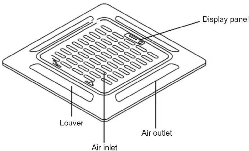
Fig 2.1
2.2 Operating Conditions
Use the system under the following temperatures for safe and effective operation. If the air conditioner is used under different conditions, it may malfunction or become less efficient.
| COOL Mode HEAT mode DRY mode | |||
| Indoor Temperature | 17-32°C(62-90°F) | 0-30°C(32-86°F) | 17-32°C(62-90°F) |
| Outdoor Temperature | 0-50°C(32-122°F) | ||
| -15-50°C(5-122°F) | -15-24°C(5-76°F) | 0-50°C(32-122°F) | |
| (low temperature cooling models) | |||
2.3 Features
Default Setting
When the air conditioner restarts after a power failure, it will default to the factory settings (AUTO mode, AUTO fan, 24°C (76°F)). This may cause inconsistencies on the remote control and unit panel. Use your remote control to update the status.
Auto-Restart (some models)
In case of power failure, the system will immediately stop. When power returns, the Operation light on the indoor unit will flash. To restart the unit, press the ON/OFF button on the remote control. If the system has an auto restart function, the unit will restart using the same settings.
Louver Angle Memory Function (Optional)
Some models are designed with a louver angle memory function. When the unit restarts after a power failure, the angle of the horizontal louvers will automatically return to the previous position. The angle of the horizontal louver should not be set too small as condensation may form and drip into the machine. To reset the louver, press the manual button, which will reset the horizontal louver settings.
Refrigerant Leak Detection System (some models)
In the event of a refrigerant leak, the LCD screen will display "EC" and the LED indicator light will flash.
2.4 Energy Saving Tips
- DO NOT set the unit to excessive temperature levels.
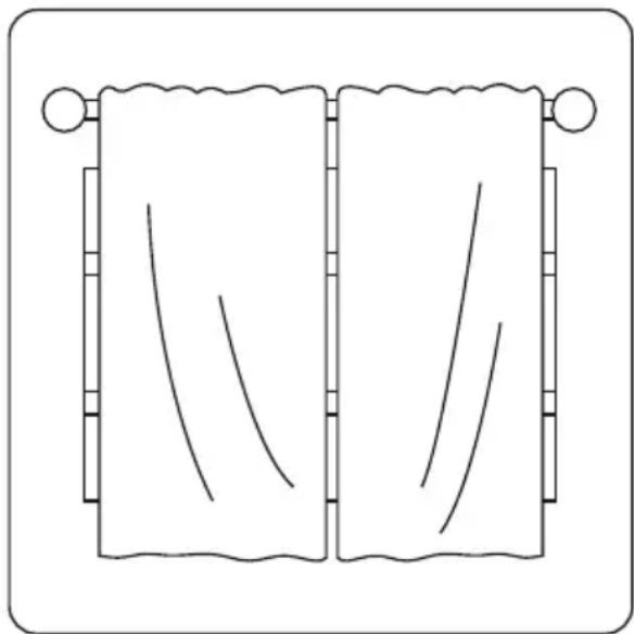
- While cooling, close the curtains to avoid direct sunlight.
- Doors and windows should be kept closed to keep cool or warm air in the room.
- DO NOT place objects near the air inlet and outlet of the unit. This will reduce the efficiency of the unit.
-
Set a timer and use the built-in SLEEP/ECONOMY mode if applicable.
-
If you don't plan to use the unit for a long time, remove the batteries from the remote control.
- Clean the air filter every two weeks. A dirty filter can reduce cooling or heating efficiency.
- Adjust louvers properly and avoid direct airflow.
natural_image
Simple line drawing of two vertical scroll panels with curved lines, no text or symbols presentClosing curtains during heating also helps keep the heat in

natural_image
Simple line drawing of a door and window (no text or symbols)Doors and windows should be kept closed
2.5 Handling the remote controller

natural_image
Simple line drawing of a rectangular device with a small circular mark on the top (no text or symbols)
Location of the remote controller.
- Keep the remote controller where its signals can reach the receiver of the indoor unit. (a distance of 8m is allowed).

CAUTIONS
- The air conditioner will not operate if curtains, doors or other materials block the signals from the remote controller to the indoor unit.
- Prevent any liquid from falling into the remote controller. Do not expose the remote controller to direct sunlight or heat.
- If the infrared signal receiver on the indoor unit is exposed to direct sunlight, the air conditioner may not function properly. Use curtains to prevent the sunlight from falling on the receiver.
- If other electrical appliances react to the remote controller, either move these appliances or consult your local dealer.
2.6 Replacing batteries

The remote controller uses two alkaline dry batteries (R03/LR03X2)
- Slide the cover of the battery compartment off according to the arrow direction, then replace the old batteries with new ones.
- Insert the new batteries making sure that the(+) and (-) of battery are installed correctly.
- Reattach the cover by sliding it back into position.
NOTE: Do not use old batteries or different type batteries or rechargeable batteries, otherwise it may cause the remote controller malfunction.
2.7 Remote Controller Specification
| Model | R51I4/BGE, R51I4/BGCE, R51I19/BGE, R51I19/BGCE RG51I47/BG(C)E |
| Rated Voltage | 3.0V(Dry batteries R03/LR03×2) |
| Signal Receiving Range | 8m |
| Environment | -5°C~60°C |
2.8 Performance Features
- Operating Mode: COOL, HEAT(Cooling only model without), DRY, FAN and AUTO.
- Timer Setting Function in 24 hours.
- Indoor Setting Temperature Range: 17°C\~30°C.
- Full function of LCD (Liquid Crystal Display)
2.9 Features of Remote controller buttons

1 TEMP Button▲Push this button to increase the indoor temperature setting in 1°C increments to 30°C.
2 ON/OFF Button: Press this button to start the indoor unit. Press again to stop the unit.
3 FAN SPEED Button: Press the button to select the Fan speed in the sequence: AUTO, LOW, MED and HIGH. Each time the button is pressed, the fan speed selection is shifted.
4 TIMER ON Button: Press this button to activate the Auto-on time setting. Each press will increase the time setting in 30 minutes increments if the setting time is lower than 10 hours. When the setting time reaches 10h, each press will increase the time setting 1 hour in increments. To cancel the Auto-on time setting, just press the button until the time setting is 0.0.
5 SLEEP Button: Active/Disable sleep function. It can maintain the most comfortable temperature and save energy. For the detail, see “sleep operation” in “USER S MANUAL”.
NOTE: While the unit is running under SLEEP mode, it would be cancelled if ON/OFF, FAN SPEED, SLEEP or MODE button is pressed.
6 TIMER OFF Button: Press this button to activate the Auto-off time setting. Each press will increase the time setting in 30 minutes increments if the setting time is lower than 10 hours. When the setting time reaches 10h, each press will increase the time setting 1 hour in increments. To cancel the Auto-off time setting, just press the button until the time setting is 0.0.
7 LOCK Button: Press this recessed button to lock all current settings, and the remote controller will not accept any operation except that of the LOCK. Use the LOCK mode when you want to prevent settings from being changed accidentally. Press the LOCK button again to cancel the LOCK function. A lock symbol will appear on the remote controller display when the lock function is activated.
8 TURBO Button: Push this button to activate the Turbo function. Turbo function enables the unit to reach the preset temperature at cooling or heating operation in the shortest time (if the indoor unit does not support this function, there is no corresponding operation happened when pressing this button.)
9 LED DISPLAY Button: Press this button to clear the display on the indoor unit, press it again to light the display.
10 RESET Button: Once the recessed RESET button is pressed, all of the current settings will be cancelled and the controller will return to the initial settings.
11 FOLLOW ME Button(on some models): Push this button to initiate the Follow Me feature, the remote display is actual temperature at its location. The remote control will send this signal to the air conditioner every 3 minutes interval until press the Follow Me button again. The air conditioner will beep to indicate the Follow Me feature has ended if it does not receive the signal during any 7 minute interval.
12 SELF CLEAN(AUTO CLEAN)
Button: Press this button under COOL or DRY mode, the self clean function is activated. Under SELF CLEAN mode, the air conditioner will automatically clean and dry the Evaporator and keep it as fresh for the next operation.
13 CLEAN AIR Button(on some models): When push this button, the Ionizer/Plasma Dust Collector(depending on models) is energized and will help to remove pollen and impurities from the air.
14 DIRECTION/SWING Button: Used to stop or start horizontal louver movement or set the desired up/down air flow direction. The louver changes 6 degree in angle for each press. If keep pushing more than 2 seconds, the louver will swing up and down automatically.
15 MODE Button: Each time the button is pressed, the operation mode is selected in the sequence of the following:

NOTE: Please do not select HEAT mode if the machine you purchased is cooling only type. Heat mode is not supported by the cooling only appliance.
16 TEMP Button▼Push this button to increase the indoor temperature setting in 1°C increments to 17°C.
Note:
- Buttons design might be slightly different from the actual one you purchased depending on individual models.
- All the functions described are accomplished by the indoor unit. If the indoor unit has no this feature, there is no corresponding operation happened when press the relative button on the remote controller.
2.10 Indicators on display panel

Mode display
Displays the current selected mode. Including AUTO, COOL, DRY, HEAT (cooling & heating models only) and FAN.
Transmission Indicator
This transmission indicator will light when remote controller transmits signals to the indoor unit.
Temp./Timer display
The temperature setting (from 17°C to 30°C) or timer setting (0\~24h) will be displayed. If FAN mode is selected, there will be no display.
ON/OFF display
This indicator will be displayed when the unit is operating.
Mode display (FAN mode)
Fan speed display
Displays the selected fan speed:
AUTO, HIGH, MED and LOW.
Nothing displays when the fan speed is selected in AUTO speed. When AUTO or DRY Mode is selected, there will be no signals displayed.
FOLLOW ME display
When pressing FOLLOW ME button in COOL or HEAT mode, the remote sensing function is activated and this indicator displays.
TIMER display
This display area shows the settings of the TIMER. That is, if only the Auto-on time function is set, it will display TIMER ON. If only the Auto-off time function is set, it will display TIMER OFF. If both functions are set, it will display TIMER ON OFF which indicates you have chosen both the Auto-on time and Auto-off time.
LOCK Indicator
LOCK display is displayed when pushing the LOCK button. Push the LOCK button to clear display.
2.11 Auto operation

When you set the air conditioner in AUTO mode, it will automatically select cooling, heating (Cooling & Heating models only), or fan only operation depending on what temperature you have selected and the room temperature.
Once you select the operating mode, the operating conditions are saved in the unit's microcomputer memory. Thereafter, the air conditioner will start operating under the same conditions when you simply push the ON/OFF button of the remote controller.
Start
Ensure the unit is plugged in and power is available. The OPERATION indicator on the display window of the indoor unit illuminates.
1 Temperature button (TEMP)
Set the desired temperature.
Normally, set it between 21°C and
28°C.
2 Mode select button (MODE) Press to select AUTO.
3 ON/OFF button
Press the ON/OFF button to start the air conditioner.
Stop
ON/OFF button
Push this button again to stop the air conditioner.
If the AUTO mode is uncomfortable, you can select the desired conditions manually.
When you select the AUTO mode, you do not have to set the fan speed. The fan speed will be automatically controlled.
2.12 COOL/HEAT/FAN operation

Start
Ensure unit is plugged and power is available.
1 Temperature button (TEMP) Set the desired temperature, the most comfortable temperature is between 21°C and 28°C.
2 Fan speed button (FAN SPEED) Press to select "AUTO", "LOW", "MED" and "HIGH".
3 Mode select button (MODE) Press to select COOL, HEAT (Cooling & Heating models only), or FAN mode.
4 ON/OFF button
Press the ON/OFF button to start the air conditioner. The OPERATION
indicator on the display panel of the indoor unit illuminates. The operating mode is selected in accordance with the room temperature and operation starts after approximately 3 minutes (If you select FAN mode, the unit will start immediately).
Stop
ON/OFF button
Push this button again to stop the air conditioner.
NOTE: The temperature cannot be controlled under FAN only mode. While in this mode, only steps 1, 3 and 4 may be performed
2.13 DRY operation

Start
Ensure unit is plugged and power is available. The OPERATION indicator on the display panel of the indoor unit starts flashing.
1 Temperature button (TEMP) Push the "TEMP" button to set the desired temperature.
2 Mode select button (MODE) Press to select DRY.
3 ON/OFF button
Press the ON/OFF button to start the air conditioner. No fan speed indicator displays. The Indoor fan speed will be automatically selected LOW.
Stop
ON/OFF button
Push this button again to stop the air conditioner
NOTE: The fan speed cannot be adjusted when the unit is in AUTO and DRY mode.

In DRY mode, due to the temperature difference between the setting temperature and the actual indoor temperature, the unit will automatically operate in COOL or FAN mode.
2.14 TIMER operation
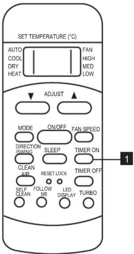
To press the TIMER ON button can set the auto-on time of the unit. To press the TIMER OFF button can set the auto-off time of the unit.
To set the Auto-on time.
- Press the TIMER ON button. The remote controller shows TIMER ON, the last Auto-on setting time and the signal "h" will be shown on the LCD display area. Now it is ready to reset the Auto-on time to START the operation.
- Push the TIMER ON button again to set desired Auto-on time. Each time you press the button, the time increases by half an hour between 0 and 10 hours and by one hour between 10 and 24 hours.
- After setting the TIMER ON, there will be a onehalf second delay before the remote controller transmits the signal to the air conditioner. Then, after approximately another 2 seconds, the signal "h" will disappear and the set temperature will re-appear on the LCD display window.

To set the Auto-off time.
-
Press the TIMER OFF button. The remote controller shows TIMER OFF, the last Auto-off setting time and the signal "h" will be shown on the LCD display area. Now it is ready to reset the Auto-off time to START the operation.
-
Push the TIMER OFF button again to set desired Auto-off time. Each time you press the button, the time increases by half an hour between 0 and 10 hours and by one hour between 10 and 24 hours.
- After setting the TIMER OFF, there will be a onehalf second delay before the remote controller transmits the signal to the air conditioner. Then, after approximately another 2 seconds, the signal "h" will disappear and the set temperature will reappear on the LCD display window.

CAUTION
- The effective operation time set by the remote controller for the timer function is limited to the following settings: 0.5, 1.0, 1.5, 2.0, 2.5, 3.0, 3.5, 4.0, 4.5, 5.0, 5.5, 6.0, 6.5, 7.0, 7.5, 8.0, 8.5, 9.0, 9.5, 10, 11, 12, 13, 14, 15, 16, 17, 18, 19, 20, 21, 22, 23 and 24.
2.15 Example of timer setting
TIMER ON
(Auto-on Operation)

The TIMER ON feature is useful when you want the unit to turn on automatically before you return home.
The air conditioner will automatically start operating at the set time.

Example:
To start the air conditioner in 6 hours.
-
Press the TIMER ON button, the last setting of starting operation time and the signal "h" will show on the display area.
-
Press the TIMER ON button to display "6.0h" on the TIMER ON display of the remote controller.
- Wait for about 3 seconds and the digital display area will show the temperature again. Now this function is activated.
TIMER OFF
(Auto-off Operation)

The TIMER OFF feature is useful when you want the unit to turn off automatically after you go to bed. The air conditioner will stop automatically at the set time. The air conditioner will automatically start operating at the set time.

Example:
To stop the air conditioner in 10 hours.
- Press the TIMER OFF button, the last setting of stopping operation time and the signal "h" will show on the display area.
- Press the TIMER OFF button to display "10h" on the TIMER OFF display of the remote controller.
- Wait for about 3 seconds and the digital display area will show the temperature again. Now this function is activated.
COMBINED TIMER

(Setting both ON and OFF timers simultaneously)
(On → Stop → Start operation)
This feature is useful when you want to stop the air conditioner after you go to bed, and start it again in the morning when you wake up or when you return home.
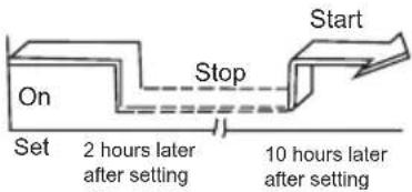
Example:
To stop the air conditioner 2 hours after setting and start it again 10 hours after setting.
- Press the TIMER OFF button.
- Press the TIMER OFF button again to display 2.0h on the TIMER OFF display.
- Press the TIMER ON button.
- Press the TIMER ON button again to display 10h on the TIMER ON display.
- Wait for the remote control to display the setting temperature.
TIMER ON → TIMER OFF
(Off → Start → Stop operation)

This feature is useful when you want to start the air conditioner before you wake up and stop it after you leave the house.
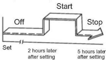
Example:
To start the air conditioner 2 hours after setting, and stop it 5 hours after setting.
- Press the TIMER ON button.
- Press the TIMER ON button again to display 2.0h on the TIMER ON display.
- Press the TIMER OFF button.
- Press the TIMER OFF button again to display 5.0h on the TIMER OFF display.
- Wait for the remote control to display the setting temperature.
2.16 RESET and LOCK buttons function

1 When you press the recessed LOCK button, all current settings are locked in and remote controller does not accept any operation except that of the LOCK.
Use the LOCK mode when you want to prevent settings from being changed accidentally. Press the LOCK button again when you want to cancel the LOCK mode.
A lock symbol will appear on the bottom right hand side of the remote controller display when the LOCK function is activated.
2 When you press the recessed RESET button, all current settings are cancelled and return to original factory settings.
2.17 DIRECTION/SWING button function
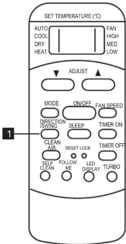
Use the DIRECTION/SWING button to activate AUTO swing function and lock louver in desired position.
1 When press this button once and quickly, the air flow direction setting feature of the louver is activated. The moving angle of the louver is 6° for each press. Keep pressing the DIRECTION/SWING button to move the louver to the desired position.
2 When press the button without releasing for 2 more seconds, the auto swing feature of the louver is activated. The horizontal louver would swing automatically. Press it again to stop.
NOTE: When the louver swing or move to a position which would affect the cooling and heating effect of the air conditioner, it would automatically change the swing/ moving direction(upward or downward).

CAUTION
-
When replacing batteries, do not use old batteries or different type batteries. Otherwise it may cause the remote controller to malfunction.
-
If you do not use the remote controller for a few weeks or more, remove the batteries. Otherwise, battery leakage may damage the remote controller.
-
The average battery life during normal use is approximately half a year. Replace the batteries when there is no receiving beep from the indoor unit or if the transmission
indicator on the remote controller fails to light.
-
Be sure there are no barriers between the remote controller and the receiver of indoor unit otherwise the air conditioner will not work.
-
Keep the Remote Controller away from all liquids.
-
Protect the Remote Controller from high temperatures and exposure to radiation.
-
Keep the indoor receiver out of direct sunlight or the Air Conditioner may malfunction.
-
Keep controller away from EMI (Electro-Magnetic Interference) supplied by other household appliances.
3. MANUAL OPERATIONS
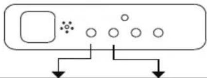
This display panel on the indoor unit can be used to operate the unit in case the remote control has been misplaced or is out of batteries.

Fig 3.1
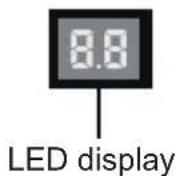
Fig 3.2
- MANUAL button: This button selects the mode in the following order: AUTO, FORCED COOL, OFF.
- FORCED COOL mode: In FORCED COOL mode, the Operation light flashes. The system will then turn to AUTO after it has cooled with a high wind speed for 30 minutes. The remote control will be disabled during this operation.
- OFF mode: When the panel is turned OFF, the unit turns o and the remote control is re-enabled.
4. CARE AND MAINTENANCE
4.1 Safety Precautions
- Contact an authorized service technician for repair or maintenance. Improper repair and maintenance may cause water leakage, electrical shock, or fire, and may void your warranty.
- DO NOT substitute a blown fuse with a higher or lower amperage rating fuse, as this may cause circuit damage or an electrical fire.
- Make sure the drain hose is set up according to the instructions. Failure to do so could cause leakage and result in personal property damage, fire and electric shock.
- Make sure that all wires are connected properly. Failure to connect wires according to instructions can result in electrical shock or fire.
4.2 Unit Maintenance
BEFORE CLEANING OR MAINTENANCE
• Always turn o your air conditioning system and disconnect the power supply before cleaning or maintenance.
- DO NOT use chemicals or chemically treated cloths to clean the unit.
- DO NOT use benzene, paint thinner, polishing powder or other solvents to clean the unit. They can cause the plastic surface to crack or deform.
- DO NOT wash the unit under running water. Doing so creates an electrical hazard.
- DO NOT use water hotter than 40°C (104°F) to clean the front panel. This can cause the panel to become deformed or discolored.
- Clean the unit using a damp, lint-free cloth and neutral detergent. Dry the unit with a dry, lint-free cloth.
4.3 How To Clean The Air Filter
The filter prevents dust and other particles from entering the indoor unit. Dust buildup can reduce the efficiency of the air conditioner. For optimum efficiency, clean the air filter every two weeks or more frequently if you live in a dusty area. Replace the filter with a new one if it's heavily clogged and cannot be cleaned.
WARNING: DO NOT REMOVE OR CLEAN THE FILTER BY YOURSELF
Removing and cleaning the filter can be dangerous. Removal and maintenance must be performed by a certified technician.
NOTE: In households with animals, you will have to periodically wipe down the grille to prevent animal hair blocking airrow.
- Unlock the grille by pushing the two tabs towards the middle simultaneously.
- Unplug the display panel cable from the control box on the main body.

Fig. 4.1
- Detach the grille from the main unit by holding the grille at a 45^ angle, lifting it up slightly and then pulling the grille forward.

natural_image
Technical diagram of a device's internal structure showing internal components and a magnified inset (no text or symbols)Fig. 4.2
- Remove the air Iter.
- Clean the air liter by vacuuming the surface or washing it in warm water with mild detergent.
A. If using a vacuum cleaner, the inlet side should face the vacuum.

natural_image
Line drawing of a vacuum cleaner connected to a grid-patterned surface on a cutting board (no text or symbols)Fig. 4.3
B. If using water, the inlet side should face down and away from the water stream.
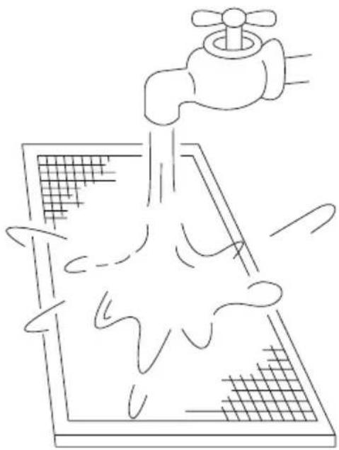
natural_image
Simple line drawing of a faucet spraying water onto a grid-patterned surface (no text or symbols)Fig. 4.4
- Rinse the Iter with clean water and allow it to air-dry. DO NOT let the Iter dry in direct sunlight.
- Reinstall the Iter.
- Reinstall the front grille and reconnect the display panel cable to the control box on the main body.
4.4 Repairing Refrigerant Leaks

WARNING
- If the refrigerant leaks, turn o the air conditioner and any combustible heating devices, ventilate the room and call your dealer immediately. Refrigerant is both toxic and flammable. DO NOT use the air conditioner until the leak is repaired.
- When the air conditioner is installed in a small room, measures must be taken to prevent the refrigerant concentration from exceeding the safety limit in the event of refrigerant leakage. Concentrated refrigerant causes a severe health and safety threat.
Refrigerant Leak Detection System (some models)
- In the event of a refrigerant leak, the LCD screen will display "EC" and the LED indicator light will flash.
4.5 Preparation For Periods Of Non-Use
Maintenance after Extended Non-Use
- Remove any obstacles blocking the vents of both the indoor and outdoor units.
- Clean the air liter and the front grille of the indoor unit. Reinstall the clean, dry air liter in its original position.
- Turn on the main power switch at least 12 hours prior to operating the unit.
Storing the Unit While Not In Use
- Run the appliance on FAN mode for 12 hours in a warm room to dry it and prevent mold.
- Turn o the appliance and unplug it.
- Clean the air liter according to the instructions in the previous section. Reinstall the clean, dry liter before storing.
- Remove the batteries from the remote control.
5. TROUBLESHOOTING

CAUTIONS
If one of the following conditions occurs, switch o the power supply immediately and contact your dealer for further assistance.
- The operation light continues to flash rapidly after the unit has been restarted.
- The remote control buttons do not work.
-
The unit continually trips fuses or circuit breakers.
-
A foreign object or water enters the air conditioner.
- Other abnormal situations.
5.1 Common Problems
The following symptoms are not a malfunction and in most situations will not require repairs.
| Problem Possible Causes | |
| Unit does not turn on when pressing ON/OFF button | The unit has a 3-minute protection feature that prevents the unit from overloading. The unit cannot be restarted within three minutes of being turned off. |
| Cooling and Heating Models: If the Operation light and PRE-DEF (Pre-heating/Defrost) indicators are lit up, the outdoor temperature is too cold and the unit's anti-cold wind is activated in order to defrost the unit. | |
| In Cooling-only Models: If the “Fan Only” indicator is lit up, the outdoor temperature is too cold and the unit's anti-freeze protection is activated in order to defrost the unit. | |
| The unit changes from COOL mode to FAN mode | The unit changes its setting to prevent frost from forming on the unit. Once the temperature increases, the unit will start operating again. |
| The set temperature has been reached, at which point the unit turns o the compressor. The unit will resume operating when the temperature fluctuates again. | |
| The indoor unit emits white mist | In humid regions, a large temperature dience between the room's air and the conditioned air can cause white mist. |
| Both the indoor and outdoor units emit white mist | When the unit restarts in HEAT mode after defrosting, white mist may be emitted due to moisture generated from the defrosting process. |
| The indoor unit makes noises | A squeaking sound is heard when the system is OFF or in COOL mode. The noise is also heard when the drain pump (optional) is in operation. |
| A squeaking sound may occur after running the unit in HEAT mode due to expansion and contraction of the unit's plastic parts. | |
| Both the indoor unit and outdoor unit make noises | A low hissing sound may occur during operation. This is normal and is caused by refrigerant gas flowing through both the indoor and outdoor units. |
| A low hissing sound may be heard when the system starts, has just stopped running or is defrosting. This noise is normal and is caused by the refrigerant gas stopping or changing direction. | |
| The outdoor unit makes noises | The unit will make dierent sounds based on its current operating mode. |
| Dust is emitted from either the indoor or outdoor unit | The unit may accumulate dust during extended periods of non-use, which will be emitted when the unit is turned on. This can be mitigated by covering the unit during long periods of inactivity. |
| The unit emits a bad odor | The unit may absorb odors from the environment (such as furniture, cooking, cigarettes, etc.) which will be emitted during operations. |
| The unit's filters have become moldy and should be cleaned. | |
| The fan of the outdoor unit does not operate | During operation, the fan speed is controlled to optimize product operation. |
5.2 Troubleshooting Tips
When troubles occur, please check the following points before contacting a repair company.
| Problem Possible Causes Solution | ||
| The unit is not working | Power failure Wait for the power to be restored | |
| The power switch is o Turn on the power | ||
| The fuse is burned out Replace the fuse | ||
| Remote control batteries are dead | Replace the remote control batteries | |
| The unit's 3-minute protection has been activated | Wait three minutes after restarting the unit | |
| Poor cooling performance | Temperature setting may be higher than the ambient room temperature | Lower the temperature setting |
| The heat exchanger on the indoor or outdoor unit is dirty | Clean the aected heat exchanger | |
| The air filter is dirty Remove the filter and clean it according to instructions. | ||
| The air inlet or outlet of either unit is blocked | Turn the unit off, remove three obstruction and turn it back on | |
| Doors and windows are open Make sure that all doors and windows are closed while operating the unit | ||
| Excessive heat is generated by sunlight | Close windows and curtains during periods of high heat or bright sunshine | |
| Low refrigerant due to leak or long-term use | Check for leaks, re-seal if necessary and top o refrigerant | |
| The unit starts and stops frequently | There's too much or too little refrigerant in the system | Check for leaks and recharge the system with refrigerant |
| There is air, incompressible gas or foreign material in the refrigeration system. | Evacuate and recharge the system with refrigerant | |
| System circuit is blocked Determine which circuit is blocked and replace the malfunctioning piece of equipment | ||
| The compressor is broken Replace the compressor | ||
| The voltage is too high or too low Install a manostat to regulate the voltage | ||
| Poor heating performance | The outdoor temperature is lower than 7°C (44.5°F) | Check for leaks and recharge the system with refrigerant |
| Cold air is entering through doors and windows | Make sure that all doors and windows are closed during use | |
| Low refrigerant due to leak or long-term use | Check for leaks, re-seal if necessary and top o refrigerant | |
5.3 Error Codes
flowchart
graph TD
    A[" "] --> B[" "]
    B --> C[" "]
    C --> D[" "]
    D --> E[" "]
    E --> F[" "]
    F --> G[" "]
    G --> H[" "]
    H --> I[" "]
    I --> J[" "]
    J --> K[" "]
    K --> L[" "]
    L --> M[" "]
    M --> N[" "]
    N --> O[" "]
    O --> P[" "]
    P --> Q[" "]
    Q --> R[" "]
    R --> S[" "]
    S --> T[" "]
    T --> U[" "]
    U --> V[" "]
    V --> W[" "]
    W --> X[" "]
    X --> Y[" "]
    Y --> Z[" "]
| Number Cause The number | of flashes per second | Timer indicator | Error code | |
| 1 Indoor EEPROM (Electrically Erasable Programmable Read-Only Memory) error | 1 Off | EO | ||
| 2 Indoor and outdoor unit communication malfunction | 2 Off | E1 | ||
| 3 Indoor fan speed malfunction 4 Off | E3 | |||
| 4 Indoor room temperature sensor error 5 Off | E4 | |||
| 5 Evaporator coil temperature sensor error | 6 Off | ES | ||
| 6 Refrigerant leak detection system malfunction | 7 Off | EC | ||
| 7 Water level alarm malfunction 8 Off | EE | |||
| 8 Dual indoor unit (twin model only) communication malfunction | 9 Off | EB | ||
| 9 Other twin model malfunction 10 Off | E9 | |||
| 10 Overload protection 1 On | FO | |||
| 11 Outdoor temperature sensor error 2 On | FI | |||
| 12 Outdoor condenser pipe sensor error 3 On | F2 | |||
| 13 Discharge air temperature sensor error 4 On | F3 | |||
| 14 Outdoor EEPROM (Electrically Erasable Programmable Read-Only Memory) error | 5 On | F4 | ||
| 15 Outdoor fan speed (DC fan motor only) malfunction | 6 | On | FS | |
| 16 Inverter module IPM protection 1 | Flash | PO | ||
| 17 High/Low voltage protection | 2 | Flash | PI | |
| 18 | Compressor top overheating protection | 3 | Flash | P2 |
| 19 | Outdoor low temperature protection | 4 | Flash | P3 |
| 20 Compressor drive error | 5 | Flash | P4 | |
| Number Cause The number | of flashes per second | Timer indicator | Error code |
| 21 Mode conflict 6 Flash | PS | ||
| 22 Compressor low-pressure protection 7 Flash | P6 | ||
| 23 Outdoor IGBT sensor error 8 Flash | P7 |
6. EUROPEAN DISPOSAL GUIDELINES
Users in European Countries may be required to properly dispose of this unit. This appliance contains refrigerant and other potentially hazardous materials. When disposing of this appliance, the law requires special collection and treatment. DO NOT dispose of this product as household waste or unsorted municipal waste.
When disposing of this appliance, you have the following options:
- Dispose of the appliance at designated municipal electronic waste collection facility.
- When buying a new appliance, the retailer will take back the old appliance free of charge.
- The manufacturer will also take back the old appliance free of charge.
- Sell the appliance to certified scrap metal dealers.

NOTE: Disposing of this appliance in the forest or other natural surroundings endangers your health and is bad for the environment. Hazardous substances may leak into the ground water and enter the food chain.
INDICE
natural_image
Simple line drawing of two vertical scroll panels with curved lines, no text or symbols presentnatural_image
Simple line drawing of a door and a window (no text or symbols)natural_image
Simple line drawing of a rectangular air conditioner unit (no text or symbols)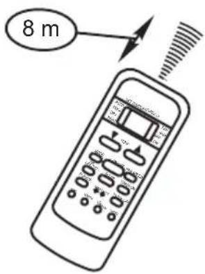
natural_image
Technical line drawing of a device's internal structure showing internal components and a magnified inset (no text or symbols)Fig. 4.2
natural_image
Line drawing of a vacuum cleaner connected to a grid-patterned surface on a cutting board (no text or symbols)Fig. 4.3
natural_image
Simple line drawing of a faucet spraying water onto a grid-patterned surface (no text or symbols)Fig. 4.4
natural_image
Simple line drawing of two vertical scroll panels with curved lines, no text or symbols presentnatural_image
Simple line drawing of a door and a window (no text or symbols)natural_image
Simple line drawing of a rectangular device with a small circular mark on the top (no text or symbols)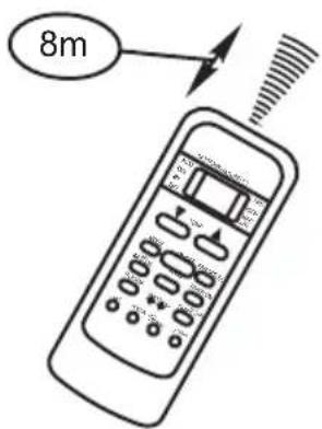
natural_image
Technical line drawing of a device's internal structure, showing internal components and an inset view (no text or symbols)Zdj. 4.2
natural_image
Line drawing of a spray gun and a cleaning board with a handle, no text or symbols presentZdj. 4.3
natural_image
Line drawing of a faucet spraying water onto a grid-patterned surface (no text or symbols)Zdj. 4.4
natural_image
Repeating pattern of white geometric shapes on a light background, no text or symbols present- WE'RE THINKING OF YOU
- Visit our website to:
- CUSTOMER CARE AND SERVICE
- ⚠ SAFETY INSTRUCTIONS
- Children and vulnerable people safety
- WARNING!
- Installation and Use
- INDOOR UNIT PARTS AND MAJOR FUNCTIONS
- Unit Parts
- Operating Conditions
- Features
- Default Setting
- Auto-Restart (some models)
- Louver Angle Memory Function (Optional)
- Refrigerant Leak Detection System (some models)
- Energy Saving Tips
- Handling the remote controller
- Location of the remote controller.
- CAUTIONS
- Replacing batteries
- Remote Controller Specification
- Performance Features
- Features of Remote controller buttons
- Note:
- Indicators on display panel
- Mode display
- Transmission Indicator
- Temp./Timer display
- ON/OFF display
- Mode display (FAN mode)
- Fan speed display
- FOLLOW ME display
- TIMER display
- LOCK Indicator
- Auto operation
- Start
- Stop
- COOL/HEAT/FAN operation
- ON/OFF button
- To set the Auto-on time.
- To set the Auto-off time.
- CAUTION
- Example of timer setting
- TIMER ON
- (Auto-on Operation)
- Example:
- RESET and LOCK buttons function
- DIRECTION/SWING button function
- MANUAL OPERATIONS
- CARE AND MAINTENANCE
- Safety Precautions
- Unit Maintenance
- BEFORE CLEANING OR MAINTENANCE
- How To Clean The Air Filter
- WARNING: DO NOT REMOVE OR CLEAN THE FILTER BY YOURSELF
- Repairing Refrigerant Leaks
- WARNING
- Preparation For Periods Of Non-Use
- Maintenance after Extended Non-Use
- Storing the Unit While Not In Use
- TROUBLESHOOTING
- Common Problems
- Troubleshooting Tips
- Error Codes
- EUROPEAN DISPOSAL GUIDELINES
- INDICE
Brand : ELECTROLUX
Model : EPF09V1K8
Category : Air conditioner