
AV100 - AV Extender Adder - Free user manual and instructions
Find the device manual for free AV100 Adder in PDF.


| Product Type | AV Extender (Transmitter & Receiver set) |
| Brand | Adder |
| Model | AV100 |
| Category | Digital Signage Extender |
| Video Resolution | Up to 1600x1200 @60Hz (at 200m); 1280x1024 @60Hz (at 300m) |
| Maximum Transmission Distance | 300m (1000 ft) via CAT5/6 twisted pair cable |
| Audio Support | Stereo audio via 3.5mm jack |
| Number of Remote Displays | 2 per receiver (plus 1 local monitor via transmitter) |
| DDC Support | Yes, automatic cloning from local monitor or default EDID |
| Cascading | Yes, up to 3 cascade connections (transmitter or receiver side) |
| Adjustments | Brightness and sharpness (on receiver) |
| Mounting Options | Desktop (adhesive feet), wall (rear slot), rack (optional chassis) |
| Power Supply | External auto-voltage (100-240V AC) with IEC connector |
| Power Consumption | Supplied via external power adapter (approx. 5V DC) |
| Indicators | Red (power), Green (video input) |
| Warranty | 2 years |
| Operating Environment | Dry, oil-free indoor only; not for outdoor or hazardous areas |
| Included Accessories | Transmitter, Receiver, power supplies (2), CD-ROM, rubber feet |
Frequently Asked Questions - AV100 Adder
User questions about AV100 Adder
0 question about this device. Answer the ones you know or ask your own.
Ask a new question about this device
Download the instructions for your AV Extender in PDF format for free! Find your manual AV100 - Adder and take your electronic device back in hand. On this page are published all the documents necessary for the use of your device. AV100 by Adder.
USER MANUAL AV100 Adder
AdderLink AV100 series
Digital Signage Extenders

CONTENTS
Contents
Welcome
Introduction....2
Standard AdderLink AV models 2
Support for DDC (Display Data Channel) 3
Further expansion....4
Transmitter cascading 4
Receiver cascading 4
What's in the box 5
What you may additionally need....5
Module features....6
Installation
Locations....7
Mounting 8
Using the self adhesive feet....8
Using the rear mounting slot....8
Using the optional rack mount chassis....9
Making standard connections....10
Connections at the transmitter....10
Connections at the receiver ....13
Making cascade connections ....15
Important limitations when cascading....15
Cascade connection examples....15
Cascading transmitters 16
Cascading receivers (AdderLink AV101 only)....17
Operation
Indicators....18
Adjustments....18
Brightness and sharpness adjustments....18
Skew compensation adjustments (AV101 only)....19
Further information
Troubleshooting 21
Getting assistance....21
Safety information 22
Warranty 22
Products in the AdderLink AV range....23
Cables 23
Emissions and Immunity....24

Welcome
Introduction
The AdderLink AV range of digital signage extenders are designed and built specifically for use wherever high quality video and sound must be faithfully reproduced at distant locations. Mindful of the need for variety and flexibility to suit disparate installations, Adder have created a family of products that can fulfil your current requirements and be easily expanded at any future stage.
Standard AdderLink AV100 models
There are three different AdderLink AV100 series transmitter and receiver module types available, the choice of each depends upon the quantity and types of devices that need to be driven:
AdderLink AV100 pair
The AdderLink AV100 package provides a single transmitter and single receiver capable of directly supporting two remote display and speaker sets. The transmitter can additionally support a local monitor and speaker set located adjacent to the source system. Expansion is made possible by connecting further AV100 transmitters to the original module, each supporting their own AV100 receiver modules. The AV100 transmitter and receiver modules are also available separately and are known as the AV100T and AV100R respectively.

flowchart
graph LR
    PC["PC"] -->|VIDEO| TRANSMITTER["100 TRANSMITTER"]
    PC -->|AUDIO| TRANSMITTER
    TRANSMITTER -->|CATx LINK UP TO 300m| RECEIVER["100 RECEIVER"]
    RECEIVER -->|Power| PC
    RECEIVER -->|Video| PC
    subgraph PC
        direction LR
        direction TB
    end
    subgraph Receiver
        direction TB
        direction TB
        direction TB
        direction TB
        direction TB
        direction TB
        direction TB
        direction TB
        direction TB
    end
AdderLink AV100 transmitter and receiver pair driving two remote displays and speakers in addition to a local monitor and speaker set
AdderLink AV104 and AV101 (or AV100)
The AdderLink AV104 transmitter and multiple AV101 modules are designed to provide potentially enormous expansion possibilities from the outset. Each AV104 transmitter is capable of directly feeding up to four AV101 receivers. Each receiver supports two remote display and speakers sets, but additionally can also drive a further three receivers and their respective displays/speakers. Additional expansion is also possible by connecting further AV104 transmitters to the original module, each supporting their own multiple AV101 receiver modules.

flowchart
graph TD
    PC["PC"] -->|VIDEO| A["104"]
    PC -->|AUDIO| B["TRANSMITTERRECEIVER"]
    A --> C["101"]
    B --> D["101"]
    C --> E["Receiver"]
    D --> F["Receiver"]
    E --> G["Receiver"]
    F --> H["Receiver"]
    G --> I["Receiver"]
    H --> J["Computer"]
    I --> K["Video"]
    J --> L["Video"]
    K --> M["Video"]
    L --> N["Video"]
    M --> O["Video"]
    N --> P["Video"]
    O --> Q["Video"]
    P --> R["Video"]
    Q --> S["Power"]
    R --> T["Power"]
    S --> U["Power"]
    T --> V["Power"]
    U --> W["Power"]
    V --> X["Power"]
    W --> Y["Power"]
    X --> Z["Power"]
    Y --> AA["Power"]
    Z --> AB["Power"]

Support for DDC (Display Data Channel)
The Display Data Channel standard allows video monitors to define their characteristics so that the source computers to which they are connected can optimise their video outputs accordingly. By their nature, the AdderLink AV extenders enable multiple video displays to be attached to a single source computer. This causes a complication for handling the DDC standard, however, in characteristic style we have devised an elegant solution, as detailed below.
Whenever an AdderLink AV transmitter is powered on, it checks its local video port for a working display monitor with DDC information. The following strictly ordered actions occur to automatically locate the most suitable DDC data:
- If a display monitor is discovered on the local video port of the transmitter, the DDC data are cloned from it and stored within the transmitter.
- If no display monitor is discovered on the local video port of the transmitter, the DDC data held within the transmitter will remain unchanged.
- If the DDC data or clock lines of the transmitter's local video port are discovered to be connected to ground, then a default set of DDC data will be reloaded and used.
After the initial search period, the stored DDC data are then presented to the video port of the source computer. When transmitters are cascaded, only the primary transmitter (the one connected to the source computer) will perform the search for DDC data.
AdderLink AV transmitters hold two pages of DDC data in order to support the most advanced display monitors. The DDC data are held within non-volatile memory so that they are retained when power is removed.
The manner in which the transmitters search for suitable 'DDC donors' could have an impact if your installation contains display units with differing capabilities. Generally, you should arrange for the display monitor with the most representative capabilities of your whole installation to be the one that the transmitter locates on its local port, either initially (and temporarily) while commissioning or permanently.
Further expansion
Transmitter cascading
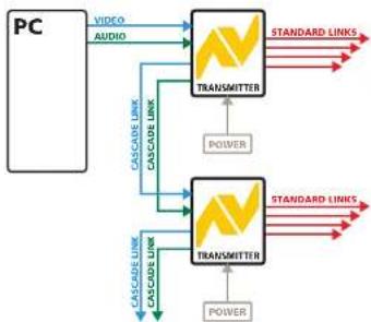
As mentioned earlier, the AV100 and AV104 transmitters are all capable of supporting additional transmitter modules (and their subsequent receivers). This is achieved using the video and audio out ports
to provide the inputs into the next transmitter module, and so on. A limit of three cascade connections (comprising both transmitter and/or receiver cascades) is possible within any branch of the system.
flowchart
graph TD
    A["PC"] --> B["VIDEO AUDIO"]
    B --> C["TRANSMITTER"]
    C --> D["STANDARD LINKS"]
    C --> E["POWER"]
    F["PC"] --> G["TRANSMITTER"]
    G --> H["STANDARD LINKS"]
    G --> I["POWER"]
    J["CASCADE LINK"] --> G
    K["CASCADE LINK"] --> G
    L["CASCADE LINK"] --> G
    M["CASCADE LINK"] --> G
    N["CASCADE LINK"] --> G
    O["CASCADE LINK"] --> G
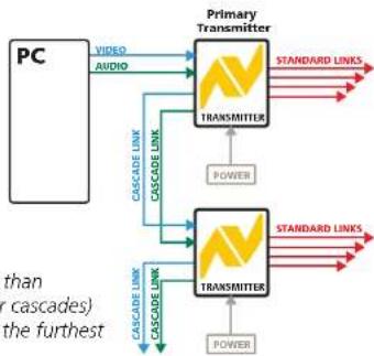
Any of the AV transmitters can be connected in cascade to provide further audio and video expansion opportunities
Receiver cascading
This method of expansion is limited to the AV101 receivers as only they are equipped with the necessary
LINK OUT cascade port. Using the LINK OUT port, the video and audio signals are transferred via CATx cabling to the next receiver.
This receiver can then drive its own dual display/speaker sets as well as provide a further LINK
OUT to a third and final AV101 receiver. A limit of three cascade connections (comprising both transmitter and/or receiver cascades) is possible within any branch of the system.

flowchart
graph TD
    A["101"] --> B["RECEIVER"]
    B --> C["101"]
    C --> D["RECEIVER"]
    D --> E["101"]
    E --> F["RECEIVER"]
    F --> G["101"]
    G --> H["RECEIVER"]
    H --> I["101"]
    I --> J["RECEIVER"]
    J --> K["101"]
    K --> L["RECEIVER"]
    L --> M["101"]
    M --> N["RECEIVER"]
    N --> O["101"]
    O --> P["RECEIVER"]
    P --> Q["101"]
    Q --> R["RECEIVER"]
    R --> S["101"]
    S --> T["RECEIVER"]
    T --> U["101"]
    U --> V["RECEIVER"]
    V --> W["101"]
    W --> X["RECEIVER"]
    X --> Y["101"]
    Y --> Z["RECEIVER"]
    Z --> AA["101"]
    AA --> AB["RECEIVER"]
    AB --> AC["101"]
    AC --> AD["RECEIVER"]
    AD --> AE["101"]
    AE --> AF["RECEIVER"]
    AF --> AG["101"]
    AG --> AH["RECEIVER"]
    AH --> AI["101"]
    AI --> AJ["RECEIVER"]
    AJ --> AK["101"]
    AK --> AL["RECEIVER"]
    AL --> AM["101"]
    AM --> AN["RECEIVER"]
    AN --> AO["101"]
    AO --> AP["RECEIVER"]
    AP --> AQ["101"]
    AQ --> AR["RECEIVER"]
    AR --> AS["101"]
    AS --> AT["RECEIVER"]
    AT --> AU["101"]
    AU --> AV["RECEIVER"]
    AV --> AW["101"]
    AW --> AX["RECEIVER"]
    AX --> AY["101"]
    AY --> AZ["RECEIVER"]
    AZ --> BA["101"]
    BA --> BB["RECEIVER"]
    BB --> BC["101"]
    BC --> BD["RECEIVER"]
    BD --> BE["101"]
    BE --> BF["RECEIVER"]
    BF --> BG["101"]
    BG --> BH["RECEIVER"]
    BH --> BI["101"]
    BI --> BJ["RECEIVER"]
    BJ --> BK["101"]
    BK --> BL["RECEIVER"]
    BL --> BM["101"]
    BM --> BN["RECEIVER"]
    BN --> BO["101"]
    BO --> BP["RECEIVER"]
    BP --> BQ["101"]
    BQ --> BR["RECEIVER"]
    BR --> BS["101"]
    BS --> BT["RECEIVER"]
    BT --> BU["101"]
    BU --> BV["RECEIVER"]
    BV --> BW["101"]
    BW --> BX["RECEIVER"]
    BX --> BY["101"]
    BY --> BZ["RECEIVER"]
    BZ --> CA["101"]
    CA --> CB["RECEIVER"]
    CB --> CC["101"]
    CC --> CD["RECEIVER"]
    CD --> CE["101"]
    CE --> CF["RECEIVER"]
    CF --> CG["101"]
    CG --> CH["RECEIVER"]
    CH --> CI["101"]
    CI --> CJ["RECEIVER"]
    CJ --> CK["101"]
    CK --> CR["RECEIVER"]
    CR --> CS["101"]
    CS --> CT["RECEIVER"]
    CT --> CU["101"]
    CU --> CV["RECEIVER"]
    CV --> CW["101"]
    CW --> CX["RECEIVER"]
    CX --> CY["101"]
    CY --> CZ["RECEIVER"]
    CZ --> DA["101"]
    DA --> DB["RECEIVER"]
    DB --> DC["101"]
    DC --> DD["RECEIVER"]
    DD --> DE["101"]
    DE --> DF["RECEIVER"]
    DF --> DG["101"]
    DG --> DH["RECEIVER"]
    DH --> DI["101"]
    DI --> DJ["RECEIVER"]
    DJ --> DK["101"]
    DK --> DL["RECEIVER"]
    DL --> DJ
The AdderLink AV101 receivers offer the further benefit of receiver cascading to provide multiple audio and video outputs on every branch

What's in the box

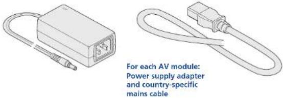

CD-ROM containing skew test pattern and documentation

Self adhesive rubber feet
What you may additionally need

natural_image
Line drawing of two connected VGA connectors (no text or symbols)Video cable to connect a transmitter to the source PC and optionally to connect additional transmitter modules in cascade. Adder P/N: VSC18

natural_image
Line drawing of a coiled cable with two connectors (no text or symbols)Stereo audio cable to connect a transmitter to the source PC and optionally to connect additional transmitter modules in cascade. Adder P/N: VSC22


natural_image
Technical line drawing of a mechanical bracket or mounting bracket with mounting holes and a curved handle (no text or symbols)For part numbers of other items, please also refer to the section Products in the AdderLink AV range.

Module features

Variation for
AV100 transmitter

Single link out connector
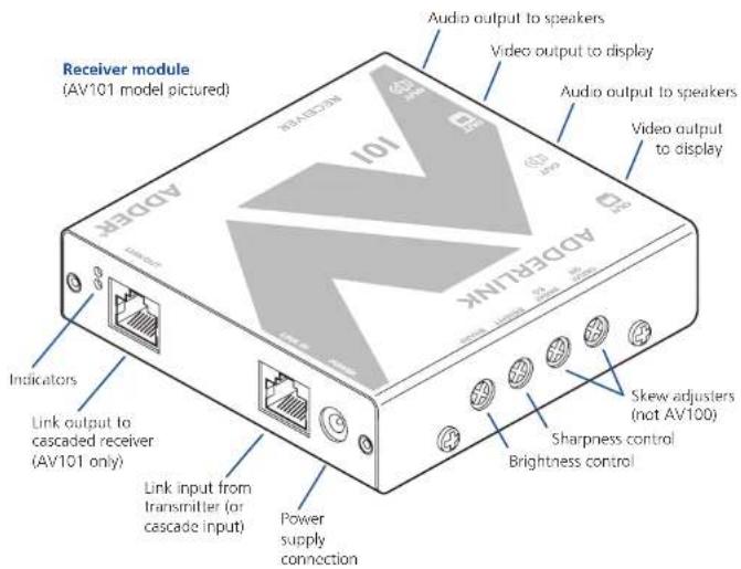
Variation for
AV100 receiver

natural_image
Diagram of a device with a grid interface and ports, no visible text or symbolsSingle link in connector
(also no skew compensation adjusters)

Installation
Locations
Please consider the following important points when planning the positions of your AdderLink AV modules:
- Take care not to exceed the maximum link cable lengths (please refer to the section Making cascade connections).
- Ensure that the transmitters are as close as possible to the source PC system and the receivers are similarly close to the display modules. Use video connection cables that are correctly shielded and are no longer than 6m in length.
- Wherever possible, choose routes for the CATx twisted pair link cables that avoid mains power cables.
- Remember a mains power socket is required for each transmitter and receiver.
- Consult the precautions listed within the Safety information section.

Mounting
Before you begin connecting to the source PC system and display devices, it is advisable to mount the AdderLink AV modules in place. There are a number of mounting possibilities for the transmitter and receiver modules:
• On a horizontal surface using the supplied self adhesive feet,
• Mounted on a screw using the rear slot,
• Within the optional rack mount chassis,
- On inclined surfaces using self adhesive Velcrostrips (not supplied).
Using the self adhesive feet
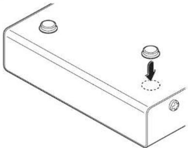
Apply the supplied self-adhesive rubber feet to the underside corners of the AdderLink AV modules.
natural_image
Technical line drawing of a mechanical bracket with two circular components and a downward arrow indicator (no text or symbols)Using the rear mounting slot
The slot at the rear of each module allows it to be hung upon a fixed screw that protrudes from the mounting surface.
IMPORTANT: The internal circuit board is accessible through the mounting slot. Ensure that any mounting screws protrudes no further than 12 " (12.5mm) into the module casing - serious electrical damage will be caused if the screw makes contact with the internal circuitry.


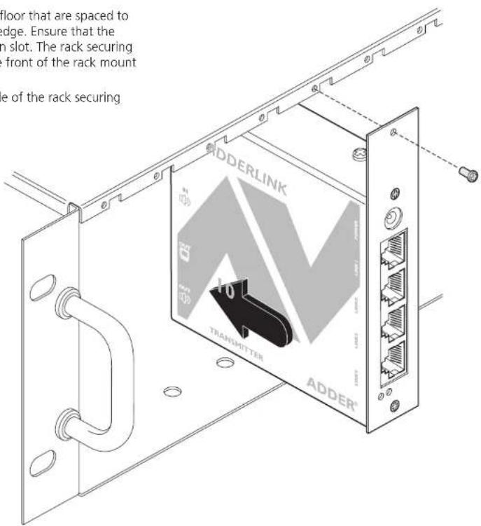
Using the optional rack mount chassis
1 Place the optional rack plate onto the front of the transmitter or receiver module and secure it with the countersunk screws.
2 Orient the module on its side so that its labelled face is the correct way up and the securing plate is facing away from the rack.
3 Slide the module into the required rack position.
4 The rack mount chassis has a series of holes in its floor that are spaced to accommodate the screws on the module's lower edge. Ensure that the screws correctly locate into the holes of the chosen slot. The rack securing plate on the module should now be flush with the front of the rack mount chassis.
5 Use the supplied (pan-head) screws, in the top hole of the rack securing plate to fasten the module to the rack.

Making standard connections
Connections to the AdderLink AV modules do not need to follow the precise order given in this user guide although it is recommended that you do not apply power to the modules until all other connections have been made.
Note: Unless stated otherwise, all connection information given here applies to all modules in the AdderLink AV family.
Connections at the transmitter
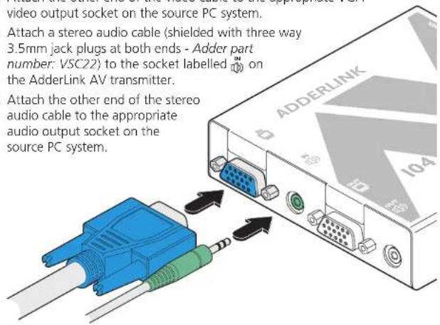
To connect video and audio from the source PC system
1 Attach a video cable of suitable type and length (fully shielded with 15 way male D-type connectors at both ends, 2m or less - Adder part number: VSC18) to the socket labelled ☐ on the AdderLink AV transmitter.
2 Attach the other end of the video cable to the appropriate VGA video output socket on the source PC system.
3 Attach a stereo audio cable (shielded with three way 3.5mm jack plugs at both ends - Adder part number: VSC22) to the socket labelled on the AdderLink AV transmitter.
4 Attach the other end of the stereo audio cable to the appropriate audio output socket on the source PC system.
To connect a monitor and speakers
The video and audio out ports of the AdderLink AV transmitter can optionally be used either to:
- Attach a monitor and/or speakers in the vicinity of the source PC system – See below, or
- Make a cascade link to another transmitter module – Please refer to the section Making cascade connections – Cascading transmitters.
1 Attach the video cable from the monitor to the socket labelled on the AdderLink AV transmitter.
2 Attach the stereo audio cable from the speakers to the socket labelled on the AdderLink AV transmitter.


To connect the link cable(s)
The links between the transmitter and receiver modules are made using between one and four twisted pair cables, specified to Category 5 or higher. Each cable carries video and audio signals to each receiver module.
When a single receiver is attached to a link cable, the maximum length of that link cable is 300m (1000 feet).

flowchart
graph LR
    A["TRANSMITTER"] -->|STANDARD LINK| B["RECEIVER"]
    B -->|Overall maximum link length: 300m| A
However, if further receivers are connected in cascade to the initial receiver using its LINK OUT port (AdderLink AV101 models only), then the overall length of the link cables used must be reduced. For further information, please refer to the section Making cascade connections.
NOTE: Where possible, avoid laying the twisted pair link cable(s) alongside power cables.
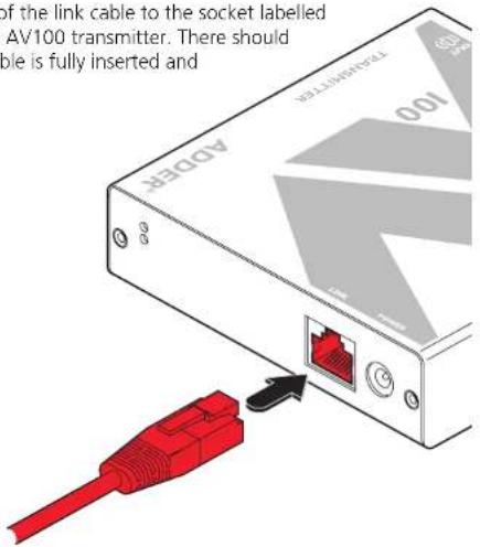
AdderLink AV100 models
1 Attach the connector of the link cable to the socket labelled LINK on the AdderLink AV100 transmitter. There should be a click when the cable is fully inserted and locked in place.
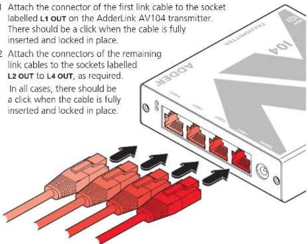
AdderLink AV104 models
1 Attach the connector of the first link cable to the socket labelled L1 OUT on the AdderLink AV104 transmitter. There should be a click when the cable is fully inserted and locked in place.
2 Attach the connectors of the remaining link cables to the sockets labelled L2 OUT to L4 OUT, as required. In all cases, there should be a click when the cable is fully inserted and locked in place.

To connect the power supply
NOTE: Please read and adhere to the electrical safety information given within the Safety information section of this guide. In particular, do not use an unearthed power socket or extension cable.
1 Attach the output connector of the power supply to the socket labelled POWER on the AdderLink AV transmitter.
2 Insert the IEC connector of the power cable into the corresponding socket of the power supply.
3 When all other connections have been made at the transmitter and receiver modules, connect the other end of the power cable to a nearby earthed mains socket.


Connections at the receiver
To connect displays and speakers
Dual video and audio outputs are provided on the AdderLink AV receiver. Both sets of ports provide identical signals and their connection procedures are the same:

Link in
The link from the transmitter to each receiver module is made using a twisted pair cable, specified to Category 5 or higher.
When a single receiver is attached to a link cable, the maximum length of that link cable is 300 metres (1000 feet).

However, if further receivers are connected in cascade to the initial receiver (using the LINK OUT port – AdderLink AV101 modules only), then the overall length of the link cables used must be reduced. For further information, please refer to the section Making cascade connections.
NOTE: Where possible, avoid laying the twisted pair link cable(s) alongside power cables.
1 Attach the connector of the link cable to the socket labelled LINK IN on the AdderLink AV receiver. There should be a click when the cable is fully inserted and locked in place.


To connect the power supply
NOTE: Please read and adhere to the electrical safety information given within the Safety information section of this guide. In particular, do not use an unearthed power socket or extension cable.
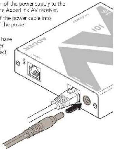
1 Attach the output connector of the power supply to the socket labelled POWER on the AdderLink AV receiver.
2 Insert the IEC connector of the power cable into the corresponding socket of the power supply.
3 When all other connections have been made at the transmitter and receiver modules, connect the other end of the power cable to a nearby earthed mains socket.

Making cascade connections
The AdderLink AV series of products have been specifically designed to be flexible in order to support both your immediate and future needs for media streaming. In addition to the standard connections made from transmitters to receivers, you can also link extra transmitters to transmitters and/or receivers to receivers in order to provide more display/speaker outputs. These non-standard links are called cascade connections.
Important limitations when cascading
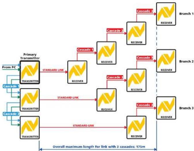
- There should never be more than three cascade connections between the primary transmitter (the one connected to the source PC) and any receiver. The cascade connections can all occur at the transmitter end or all at the receiver end (AV101 modules only) or at a mixture of both.
- Each cascade connection reduces the overall link length permissible from a transmitter to the final receiver in a branch. To calculate the recommended overall maximum link length for a branch, count the number of cascade connections between the primary transmitter and the final receiver in that branch. The effects of cascade connections on overall branch link lengths are as follows:
Number of cascade connections Overall length of links for a branch (in a branch) (from transmitter to furthest receiver)
| 0 | 300m (1000 feet) |
| 1 | 250m (800 feet) |
| 2 | 200m (650 feet) |
| 3 | 175m (600 feet) |
Notes
The lengths of transmitter cascade (video) connections should never be longer than 2m (6 feet) and can be considered to have a negligible effect upon overall link lengths.
The maximum resolutions achievable are: 1600 x 1200 x 60Hz at 200m and 1280 x 1024 x 60Hz at 300m. If you are using lower resolutions then it may be possible to achieve longer transmission distances than shown in the above table although we do not recommend runs longer than 300m in any installation. If you are running shorter cables then it may be possible to use more cascades than shown in the above table.
Cascade connection examples
These examples demonstrate valid configurations and the effect of cascade connections upon overall link lengths:

flowchart
graph TD
    A["TRANSMITTER"] -->|STANDARD LINK| B["RECEIVER"]
    B -->|Cascade 1| C["RECEIVER"]
    C -->|Branch 1| D["RECEIVER"]
    D -->|Branch 2| E["RECEIVER"]
    E -->|Overall maximum length for link with 1 cascade: 250m| A
    E -->|Overall maximum length for link with no cascades: 300m| E
flowchart
graph TD
    A["Primary Transmitter"] -->|STANDARD LINK| B["RECEIVER"]
    A -->|STANDARD LINK| C["RECEIVER"]
    B -->|Cascade 1| D["RECEIVER"]
    B -->|Cascade 2| E["RECEIVER"]
    C -->|Cascade 3| F["RECEIVER"]
    C -->|Cascade 4| G["RECEIVER"]
    D --> H["RECEIVER"]
    E --> I["RECEIVER"]
    F --> J["RECEIVER"]
    G --> K["RECEIVER"]
    H --> L["Branch 1"]
    I --> M["Branch 2"]
    J --> N["Branch 3"]
    K --> O["Branch 3"]
    P["From PC"] --> Q["Transmitter"]
    R["Cascade 1"] --> S["Transmitter"]
    T["Cascade 2"] --> U["Transmitter"]
    V["Overall maximum length for link with 3 cascades: 175m"] --> W["RECEIVER"]

Cascading transmitters
Expansion at the transmitter end is achieved using the video and audio output ports. The signals from these ports are connected to the video and audio inputs of the next transmitter and so on. AdderLink AV100 and AV104 transmitters can be mixed in a cascade in any order using the method discussed here.
NOTE: Ensure that there are no more than three cascades (transmitter or receiver cascades) between the primary transmitter and the furthest receiver in any branch.
flowchart
graph TD
    PC["PC"] -->|VIDEO AUDIO| PrimaryTransmitter1["Primary Transmitter"]
    PrimaryTransmitter1 -->|STANDARD LINKS| SecondaryTransmitter2["Secondary Transmitter"]
    PrimaryTransmitter1 -->|STANDARD LINKS| Power1["POWER"]
    PrimaryTransmitter2 -->|STANDARD LINKS| Power2["POWER"]
    subgraph PrimaryTransmitter1
        A["TRANSMITTER"]
        B["TRANSMITTER"]
    end
    subgraph SecondaryTransmitter2
        C["TRANSMITTER"]
        D["TRANSMITTER"]
    end
    note["than (c cascades) the furthest"]
To connect cascaded transmitters
1 Attach a video cable of suitable type and length (fully shielded with 15 way male D-type connectors at both ends, 2m or less - Adder part number: VSC18) to the socket labelled ☐ on the primary AdderLink AV transmitter.
2 Attach the other end of the video cable to the socket labelled ☐ on the secondary AdderLink AV transmitter.
3 Attach a stereo audio cable (shielded with three way 3.5mm jack plugs at both ends - Adder part number: VSC22) to the socket labelled on the primary AdderLink AV transmitter.
4 Attach the other end of the stereo audio cable to the socket labelled 📋 on the secondary AdderLink AV transmitter.
5 Repeat such cascade links until the required number of transmitters (up to a maximum of four) are present. Connect the remaining signal and power cables to the added transmitters (and their respective receivers) as discussed earlier within this chapter.


Cascading receivers (AdderLink AV101 only)
Expansion at the receiver end is made possible using the LINK OUT ports present on AdderLink AV101 receivers. Receiver cascade links are made using twisted pair cables, specified to Category 5 or higher. NOTE: Ensure that there are no more than three cascades (transmitter or receiver cascades) between the primary transmitter and the furthest receiver in any branch.
Video image adjustments
As link cable lengths increase and more receivers are cascaded, colour separation effects may become noticeable within displayed video images, particularly at higher resolutions. These effects are called 'skew' and result from differing delays on the red, green and blue colour signals as they travel to the receivers. Each AdderLink AV101 receiver provides two extra adjustment dials to counter skew effects. For further information, please refer to the section Skew compensation adjustments.
To connect cascaded receivers
NOTE: Please observe the recommended overall link cable lengths (including receiver cascade connections) in order to avoid signal degradation.
1 Attach the connector of the cascade link cable to the socket labelled LINK OUT on the primary AdderLink AV101 receiver.
2 At the other end of the cascade link cable, attach the connector to the socket labelled LINK IN on the secondary AdderLink AV101 receiver.
In all cases, there should be a click when the cable is fully inserted and locked in place.
3 If necessary, repeat the above procedure for a tertiary AdderLink AV101 receiver.
4 Connect the remaining signal and power cables to the added receivers, as discussed earlier within this chapter.

flowchart
graph TD
    A["101"] -->|CASCADE LINK| B["101"]
    B --> C["RECEIVER"]
    C --> D["Computer"]
    D --> E["Power"]
    F["101"] -->|STANDARD LINK| G["RECEIVER"]
    G --> H["Computer"]
    H --> I["Power"]
    J["101"] --> K["CASCADE LINK"]
    K --> L["RECEIVER"]
    L --> M["Computer"]
    M --> N["Power"]
    O["101"] --> P["CASCADE LINK"]
    P --> Q["RECEIVER"]
    Q --> R["Computer"]
    R --> S["Power"]
    T["101"] --> U["CASCADE LINK"]
    U --> V["RECEIVER"]
    V --> W["Computer"]
    W --> X["Power"]


Operation
In operation, the AdderLink AV modules are designed to be completely transparent - high quality video and audio from the source PC system are played as normal, the only difference is that they are now being seen and heard up to 300 metres away.
Indicators
All AdderLink AV modules are equipped with two indicators to confirm operation and, if necessary, assist with quick troubleshooting of potential problems.
The indicators are located on one of the end panels, near to the LINK port and operate as follows:
- RED When lit, indicates the presence of power into the module,
- GREEN When lit, indicates the presence of a video input into the module.

natural_image
Diagram of an Ethernet device showing ports, cables, and connectors (no text or symbols)Adjustments
Video signals are susceptible to the effects of long distance cables and for this reason, every AdderLink AV receiver includes brightness and sharpness adjustment dials. Additionally, the AdderLink AV101 receivers are also equipped with two extra dials to eliminate the effects of colour skew within the video image.
Brightness and sharpness adjustments
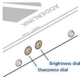
The brightness and sharpness adjustments provided on every AdderLink AV receiver allow you to compensate for any losses incurred within long cable links. These two adjustments can be made in any order and independently of each other.
When making adjustments it is necessary to have access to the AdderLink AV receiver and to be able to view one or both connected display screens. Both adjustments, sharpness in particular, are made easier when viewing high contrast images with vertical edges, such as black lines on a white background.
NOTE: Both video outputs are equally affected by your brightness and/or sharpness adjustments.
To display a suitable high contrast image
- Open a word processor, type the capital letter 'H', or 'M' and increase the point size to 72 or higher. For best results, the background should be white and the character should be black.
- A BLACK shadow on the right of the character indicates UNDER compensation.
- A WHITE shadow on the right of the character indicates OVER compensation.

To adjust brightness and/or sharpness
1 Carefully insert a small screwdriver into the dial labelled BRIGHT or SHARP, as appropriate.
2 Slowly turn the dial clockwise or anticlockwise and observe the effect shown on the screen. Withdraw the screwdriver when the displayed image is shown at its optimum clarity.
3 If necessary, repeat step 2 for the other dial.

Skew compensation adjustments (AV101 only)
The twisted pair cabling used to link the AdderLink AV modules consists of four pairs of wires per cable. Three of these pairs are used to convey the red, green and blue video signals. Due to slight differences in twist rate between the wire pairs, the red, green and blue video signals may not arrive at precisely the same time. This effect is visible as separate colour shadows on high contrast images and is particularly apparent when using higher screen resolutions over long distances and also when using certain types of category 5e cables.


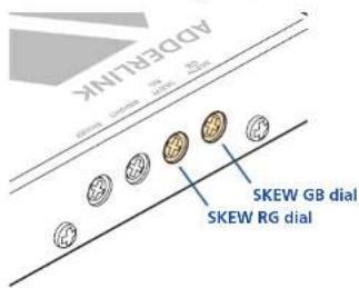
Skew compensation adjustments are made using two rotary dials, the first affects the relationship between the green and blue colour signals (SKEW
GB) while the second (SKEW RG) operates similarly on the red and green signals. Each dial delays one of its stated colours in relation to the other. By using both dials it is possible to correctly align all three colours. The effects of skew are easiest to view and adjust when distinct red, green and blue elements, in close proximity, are present within the screen image. An appropriate test pattern is supplied on the AdderLink AV CD-
ROM or alternatively you can create your own test pattern as discussed opposite.
NOTE: Both video outputs are equally affected by your skew adjustments.
To create a skew test pattern
1 Run any image creation/editing application, such as the Paint program supplied with Windows.
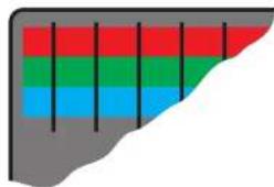
2 Using the image application create three stacked horizontal rectangles (one red, one green and one blue) that fill the width of the screen.
3 Draw a vertical black line down across the coloured bars and then repeat this vertical line at intervals along the width of the coloured bars. These lines create breaks across the colours and give you more opportunities to view the horizontal position of each colour relative to the others.
To display the supplied skew test pattern
1 Insert the supplied Adder CD-ROM into the CD player of the computer.
2 Within Windows, use the My Computer option (usually available as a desktop icon or within the Start menu) to view the contents of the CD-ROM. Double-click the SkewTest entry to display the standard test pattern. If necessary, select the Full screen option from the File menu to maximise the application window so that the image fills the screen.
The screen will show a series of fine red, green and blue crosses which should all be in line, vertically and horizontally-skew affects the horizontal placement of the colours.
natural_image
Abstract geometric pattern with vertical colored bars (red, green, blue) on gray background, no text or symbols present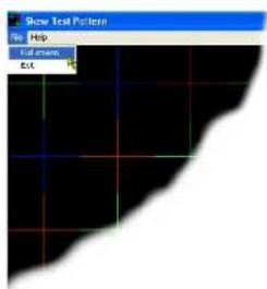

To zero the skew adjustment dials
When supplied, the two skew dials are set in their neutral positions. i.e. no delay to either of its colours. However, if the module has been previously used and adjusted then you may need to relocate the zero point. There are no setting markers around the two skew dials and the dial itself does not have a pointer.
1 Insert a small screwdriver into the skew dial and twist it all the way anticlockwise. Note the position of the dial when it reaches its end point.
2 Rotate the screwdriver fully clockwise and again note the endpoint position of the dial.
3 Now rotate the screw driver anticlockwise until the dial reaches the position that lies midway between the two end points. This is the neutral position.
4 Repeat this procedure for the other skew dial, if necessary.

To adjust the skew compensation
Your chances of achieving a successful skew compensation adjustment will be improved if you do the following:
• Ensure that you have a clear view of one or both display screens,
- Display a suitable RGB test pattern, either the supplied pattern or a self-created version,
• Use a screwdriver of an appropriate size to adjust the dials,
- Begin with both skew dials in their neutral positions - if the module has been previously used and skew adjusted for an alternative installation, zero the dials as described in the section 'To zero the skew adjustment dials' left.
Skew RG Skew GB


1 Turn the SKEW RG dial clockwise or anticlockwise until you observe that the red and green colours are aligned.
2 Turn the SKEW GB dial clockwise or anticlockwise until you observe that the green and blue colours are aligned.
3 Your actions in step 2 may alter the Red/Green alignment. If so, go back to the SKEW RG dial and turn it clockwise or anticlockwise until you observe that the Red and Green colours are aligned, at which point all of the colours will be aligned.

Further information
Troubleshooting
If you experience problems when installing or using the AdderLink AV modules, please check through this section for a possible solution. If your problem is not listed here and you cannot resolve the issue, then please refer to the 'Getting assistance' section.
No video image is received at the receiver module.
- Check that the both the red power indicators are lit on both the transmitter and receiver modules - if they are not, then there is a power problem. Both modules require power from their supplied power adapters.
- Check that the green video input indicators are lit on both the transmitter and receiver modules - if one or both are not lit, then a valid video input signal is not present at the input to that module.
- Check the link cable(s) that connect the transmitter and receiver module(s) for soundness and correct wiring as per the diagram in the 'Skew compensation adjustments' section in the 'Operation' chapter.
- If possible, try using an alternative twisted pair link connection between the modules.
- If the sharpness control is set too high, the monitor may not be able to display a picture. Try reducing the sharpness setting. Please refer to the 'Adjustments' section in the 'Special Configuration' chapter.
- If not already fitted, connect a monitor to the port of the transmitter module and check for a correct video image output.
Video image at the receiver module is distorted or shadows appear to the right of displayed objects.
Adjustments are required to compensate for the length of the twisted pair cable being used. If video problems persist:
- Please refer to the 'Brightness and sharpness adjustments' section in the 'Operation' chapter.
- If the overall video image is 'fuzzy' and/or has coloured shadows you may need to make skew adjustments (AdderLink AV101 receivers only). This procedure allows you to finely tune the red, green and blue video signal timings to overcome most colour separation problems. Please refer to the 'Skew compensation adjustment' section in the 'Operation' chapter.
Power is applied via the power supply but the module operation has stopped.
- Each module has an internal automatic cut-out fuse to protect against power surges. To reset, remove power from the module for one second and then reconnect.
No sound can be heard on the speakers connected to the receiver module
- If not already fitted, connect speakers to the port of the transmitter module and check for a correct audio output.
- Check that the both the red power indicators are lit on both the transmitter and receiver modules - if they are not, then there is a power problem. Both modules require power from their supplied power adapters.
Getting assistance
If you are still experiencing problems after checking the information contained within this guide, then we provide a number of other solutions:
• Online solutions and updates – www.adder.com/support
Check the Support section of the adder.com website for the latest solutions and firmware updates.
- Adder Forum – forum.adder.com
Use our forum to access FAQs and discussions.
- Technical support – www.adder.com/contact-support-form
For technical support, use the contact form in the Support section of the adder.com website - your regional office will then get in contact with you.

Safety information
• For use in dry, oil free indoor environments only.
• Do not use to link between buildings.
- Not suitable for use in hazardous or explosive environments or next to highly flammable materials.
- Ensure that all twisted pair interconnect cables are installed in compliance with all applicable wiring regulations.
- Do not connect the CATx link interface (RJ45 style connector) to any other equipment, particularly network or telecommunications equipment.
- Where possible, avoid laying the twisted pair link cable(s) alongside power cables.
- Warning – the power adapter contains live parts.
- No user serviceable parts are contained within the power adapter - do not dismantle.
- The primary means to cease operation of the modules is to remove the power adapter lead. Ensure that the power adapter is positioned near to the equipment and is easily accessible.
- Do not use the power adapter if the power adapter case becomes damaged, cracked or broken or if you suspect that it is not operating properly.
- Replace the power adapter with a manufacturer approved type only.
- If you use a power extension cable with the modules, make sure the total ampere rating of the devices plugged into the extension cable do not exceed the cable's ampere rating. Also, make sure that the total ampere rating of all the devices plugged into the wall outlet does not exceed the wall outlet's ampere rating.
- Do not attempt to service the modules yourself.
- The modules and power supplies can get warm in operation – do not situate them in an enclosed space without any ventilation.
- The modules do not provide ground isolation and should not be used for any applications that require ground isolation or galvanic isolation.
- Use only with grounded outlets at both the computer and monitor. When using a backup power supply (UPS), power the computer, the monitor and the module from the same supply.
- For correct operation, the transmitter and receiver modules must have ground connections. At the computer end, this is achieved by ensuring that the computer that the module is connected to has a ground connection. At the audio/visual device end, this can be achieved by ensuring that the power supply is connected to a grounded power outlet. Alternatively, a ground connection will be made via the monitor, if the monitor is itself grounded.
Warranty
Adder Technology Ltd warrants that this product shall be free from defects in workmanship and materials for a period of two years from the date of original purchase. If the product should fail to operate correctly in normal use during the warranty period, Adder will replace or repair it free of charge. No liability can be accepted for damage due to misuse or circumstances outside Adder's control. Also Adder will not be responsible for any loss, damage or injury arising directly or indirectly from the use of this product. Adder's total liability under the terms of this warranty shall in all circumstances be limited to the replacement value of this product. If any difficulty is experienced in the installation or use of this product that you are unable to resolve, please contact your supplier.

Products in the AdderLink AV range
The following items are available within the AdderLink AV product range:
- AdderLink AV100 pair (part number: ALAV100P) One AdderLink AV100 transmitter and one AdderLink AV100 receiver.
- AdderLink AV100 transmitter (part number: ALAV100T) Single AdderLink AV100 transmitter.
- AdderLink AV100 receiver (part number: ALAV100R) Single AdderLink AV100 receiver.
- AdderLink AV104 transmitter (part number: ALAV104T) Single AdderLink AV104 transmitter.
- AdderLink AV101 receiver (part number: ALAV101R) Single AdderLink AV101 receiver.
- Replacement power supply (part number: PSU-ALAV-IEC) One auto-voltage sensing power supply with country specific IEC cable
- Rack mount chassis (part number: ALAV-RMK-CHASSIS)
One 19" chassis is 3U high and capable of accommodating up to sixteen AdderLink AV transmitter or receiver modules.
• Universal rack mount securing plate (part number: ALAV-RMK-FASCIA)
Cables
These cables are available for use when connecting the modules to systems and peripherals:
• Video cable - 2 metres (part number: VSC18)
• Audio cable - 3.5 metres (part number: VSC22)
- Serial cable - 9 way male to 9 way female D-type, 2 metres (part number: CAB-9M/9F-2M)

Emissions and Immunity
A Category 5 (or better) twisted pair cable must be used to connect the modules in order to maintain compliance with radio frequency energy emission regulations and ensure a suitably high level of immunity to electromagnetic disturbances.
All other interface cables used with this equipment must be shielded in order to maintain compliance with radio frequency energy emission regulations and ensure a suitably high level of immunity to electromagnetic disturbances.
European EMC directive 89/336/EEC
This equipment has been tested and found to comply with the limits for a class A computing device in accordance with the specifications in the European standard EN55022. These limits are designed to provide reasonable protection against harmful interference. This equipment generates, uses and

can radiate radio frequency energy and if not installed and used in accordance with the instructions may cause harmful interference to radio or television reception. However, there is no guarantee that harmful interference will not occur in a particular installation. If this equipment does cause
interference to radio or television reception, which can be determined by turning the equipment on and off, the user is encouraged to correct the interference with one or more of the following measures: (a) Reorient or relocate the receiving antenna. (b) Increase the separation between the equipment and the receiver. (c) Connect the equipment to an outlet on a circuit different from that to which the receiver is connected. (d) Consult the supplier or an experienced radio/TV technician for help.
FCC Compliance Statement (United States)
This equipment generates, uses and can radiate radio frequency energy and if not installed and used properly, that is, in strict accordance with the manufacturer's instructions, may cause interference to radio communication. It has been tested and found to comply with the limits for a class A computing device in accordance with the specifications in Subpart J of part 15 of FCC rules, which are designed to provide reasonable protection against such interference when the equipment is operated in a commercial environment. Operation of this equipment in a residential area may cause interference, in which case the user at his own expense will be required to take whatever measures may be necessary to correct the interference. Changes or modifications not expressly approved by the manufacturer could void the user's authority to operate the equipment.
Canadian Department of Communications RFI statement
This equipment does not exceed the class A limits for radio noise emissions from digital apparatus set out in the radio interference regulations of the Canadian Department of Communications.
Contact: www.adder.com/contact-details
Support: forum.adder.com
Documentation by: www.ctxd.com

© 2012 Adder Technology Limited
All trademarks are acknowledged.
Part No. MAN-ALAV • Release 1.3b

- AdderLink AV100 series
- Digital Signage Extenders
- Contents
- Welcome
- Installation
- Operation
- Further information
- Introduction
- Standard AdderLink AV100 models
- AdderLink AV100 pair
- AdderLink AV104 and AV101 (or AV100)
- Support for DDC (Display Data Channel)
- Further expansion
- Transmitter cascading
- Receiver cascading
- Locations
- Mounting
- Using the self adhesive feet
- Using the rear mounting slot
- Using the optional rack mount chassis
- Making standard connections
- Connections at the transmitter
- To connect video and audio from the source PC system
- To connect a monitor and speakers
- To connect the link cable(s)
- AdderLink AV100 models
- AdderLink AV104 models
- To connect the power supply
- Connections at the receiver
- To connect displays and speakers
- Link in
- Making cascade connections
- Important limitations when cascading
- Notes
- Cascade connection examples
- Cascading transmitters
- To connect cascaded transmitters
- Cascading receivers (AdderLink AV101 only)
- Video image adjustments
- To connect cascaded receivers
- Indicators
- Adjustments
- Brightness and sharpness adjustments
- To display a suitable high contrast image
- To adjust brightness and/or sharpness
- Skew compensation adjustments (AV101 only)
- To create a skew test pattern
- To display the supplied skew test pattern
- To zero the skew adjustment dials
- To adjust the skew compensation
- Troubleshooting
- No video image is received at the receiver module.
- Video image at the receiver module is distorted or shadows appear to the right of displayed objects.
- Power is applied via the power supply but the module operation has stopped.
- No sound can be heard on the speakers connected to the receiver module
- Getting assistance
- Safety information
- Warranty
- Products in the AdderLink AV range
- Cables
- Emissions and Immunity
- European EMC directive 89/336/EEC
- FCC Compliance Statement (United States)
- Canadian Department of Communications RFI statement
Brand : Adder
Model : AV100
Category : AV Extender