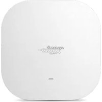
WL-ICDBG24-073 - Access Point Mach Power - Free user manual and instructions
Find the device manual for free WL-ICDBG24-073 Mach Power in PDF.


| Product Type | Wireless Access Point |
| Brand | Mach Power |
| Model | WL-ICDBG24-073 |
| Frequency Bands | 2.4 GHz & 5 GHz (Dual Band) |
| Maximum Data Rate | 750 Mbps |
| Interfaces | 1x Gigabit WAN, 1x Gigabit LAN |
| Power Supply | PoE (48V IEEE 802.3af) |
| LED Indicators | Power (Green), WiFi (Blue) |
| Operation Modes | Access Point, Gateway, WiFi Repeater, WISP |
| Management | Web GUI (HTTP) |
| Reset Button | Yes (press 15 seconds for factory reset) |
| Dimensions (Estimated) | 180 mm diameter x 40 mm height |
| Weight (Estimated) | 300 g |
| Certifications | CE, RoHS |
| Firmware Upgrade | Via Web GUI (Advanced Settings) |
Frequently Asked Questions - WL-ICDBG24-073 Mach Power
User questions about WL-ICDBG24-073 Mach Power
0 question about this device. Answer the ones you know or ask your own.
Ask a new question about this device
Download the instructions for your Access Point in PDF format for free! Find your manual WL-ICDBG24-073 - Mach Power and take your electronic device back in hand. On this page are published all the documents necessary for the use of your device. WL-ICDBG24-073 by Mach Power.
USER MANUAL WL-ICDBG24-073 Mach Power
WIRELESS ACCESS POINT DUAL BAND 750MBPS WL-ICDBG24-073
USER MANUAL
Thanks
for chosen our product
INDEX
Chapter 1 Hardware and Operation mode Instruction
1.1 LED indicator
1.2 AP Interface
1.3 Power Supply
1.3.1 PoE Adapter Power Supply
1.3.2 Powered by PoE Switch
1.3.3 Connect Wireless AP with PC
Chapter 2 Login
Chapter 3 WEB GUI interface Setting
3.1 Status
3.2 Wizard Configuration
3.2.1 Gateway Mode
3.2.2 WiFi Repeater mode
3.2.3 WISP Operation mode
3.2.4 AP operation mode
3.3 Advanced Setting
Chapter 4 Share Internet and Obtain IP address automatically
Chapter 5 Trouble Shooting
Chapter 6 Declaration of conformity
CHAPTER1
HARDWARE AND OPERATION MODE INSTRUCTION
1.1 LED indicator
Green: Power Indicator
Blue: WiFi Indicator
1.2 AP Interface
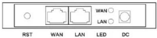
RST: Reset Button, it make AP revert to default data after press it 15 sec.
WAN: Gigabit WAN Port, connect with ADSL modem or Internet mainly. It will be LAN port under Wireless AP and WiFi Repeater operation mode
LAN: Gigabit LAN Port to end users
LED: LED Indicator of WAN port and LAN port
DC: DC power connector
1.3 Power Supply
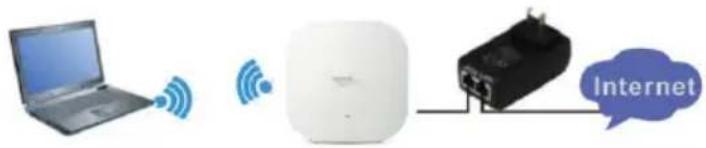
1.3.1 PoE Adapter Power Supply
The connection diagram showed as next image, internet cable connect to PoE adapter's LAN Port, Ceiling AP's WAN port connect to PoE adapter's PoE Port, then PC will access into ceiling AP through cable or wireless. Please note, if the PD Wireless AP support 48V PoE, then the PoE adapter should be 48V PoE. If the PD wireless AP support 48V IEEE 802.3af standard PoE, the PoE adapter should be 48V PoE standard.
1.3.2 Powered by PoE Switch
The connection diagram shows as next image, Internet cable from PoE Switch to Ceiling AP's WAN Port, then PC access into ceiling AP wired/wireless. PIs note, if the PD Wireless AP support 48V PoE, then the PoE switch should be 48V PoE.
If the PD wireless AP support 48V IEEE 802.3af standard PoE, m the PoE switch should comply with 802.3af 48V PoE standard.
![graph LR A["Internet"] --> B["POE Switch"] B --> C["Laptop"] style A fill:#f9f,stroke:#333 style B fill:#ccf,stroke:#333 style C fill:#cfc,stroke:#333](/content/2026/05/1074522/images/931ce2bc431c21f1a4cb7fb78843ae57f709175b2ed4f6ee81e396f9d8ec03bd.jpg)
1.3.3 Connect Wireless AP with PC
Use can connect the PC with wireless AP by Wireless SSID and LAN cable: The diagram of wireless connection showed as follow:
Note:
- Connect the Ceiling AP with computer
- Configure the PC's local connection IP address as 192.168.0.X (X is number from 2 to 253), subnet mask is 255.255.255.0, follow the image.

- Input 192.168.0.254 into IE browser, then pop up the login page, the d fault login user name: Admin, Passwords: admin, pls do following image.

CHAPTER3
WEB GUI INTERFACE SETTING
3.1 Status
After login, then Device Status will be showed:

In this ceiling wireless AP, the default operation mode is AP mode.
Then in 2.4G Wireless Setting, GUI configuration page showed as below: User can configure the SSID, password, band width, channel here, then Apply to finish.
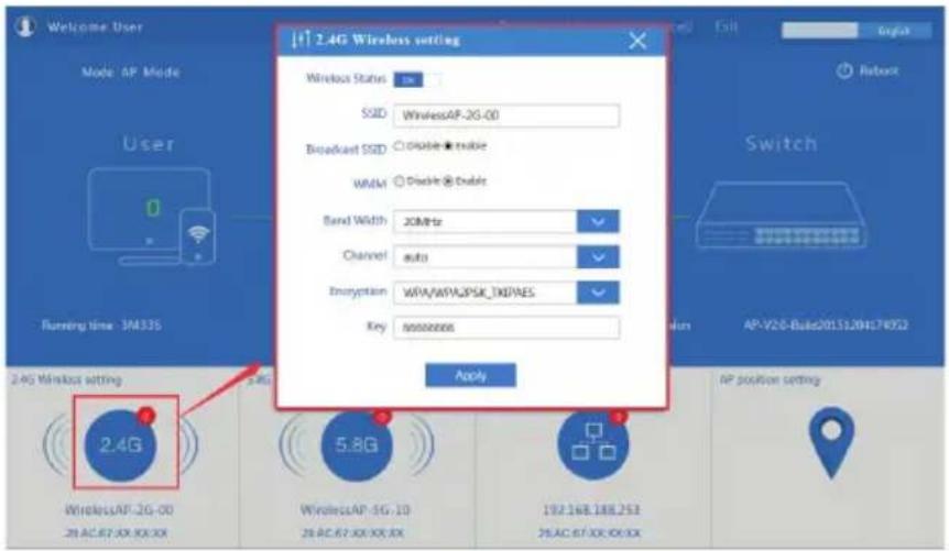
5.8G Wireless Setting GUI configuration setting showed as previus image.

LAN Setting to configure the DHCP or Fix IP
![[+] LAN setting Access Type Static IP Apply Mode AP Mode User Running time 6M345 2.4G Wireless setting WirelessAP-2G-00 28:AC 67:XX:XX:XX 5.8G Wireless setting WirelessAP-3G-10 28:AC 67:XX:XX:XX LAN setting 102.168.388.253 28:AC 67:XX:XX:XX AP position setting English Reboot Switch Software Version…](/content/2026/05/1074522/images/651932c385f5ef302f288fbe042520349633d513faa0ab519d2260ad9c6a450d.jpg)
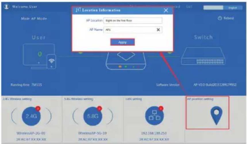
AP location setting: can mark where the AP set up, and AP name as netx image:
3.2 Wizard Configuration
Click Wizard in Status page, will pop up following page to configure the operation mode:
There are four operation mode of this ceiling wireless AP, and there are explanation for each operation mode for better application.

3.2.1 Gateway Mode
Click Gateway mode, will pop up following pictures:
Pls choose the right WAN setting mode, then click next to continue


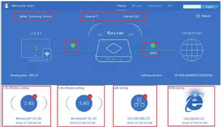
When click Next, then will complete the Gateway mode setting and show following picture:

When return to Status, the page showed as follow:
3.2.2 WiFi Repeater mode
Click WiFi Repeater operation mode in Wizard, then following page will pop up, and choose the right SSID to bridge, then next

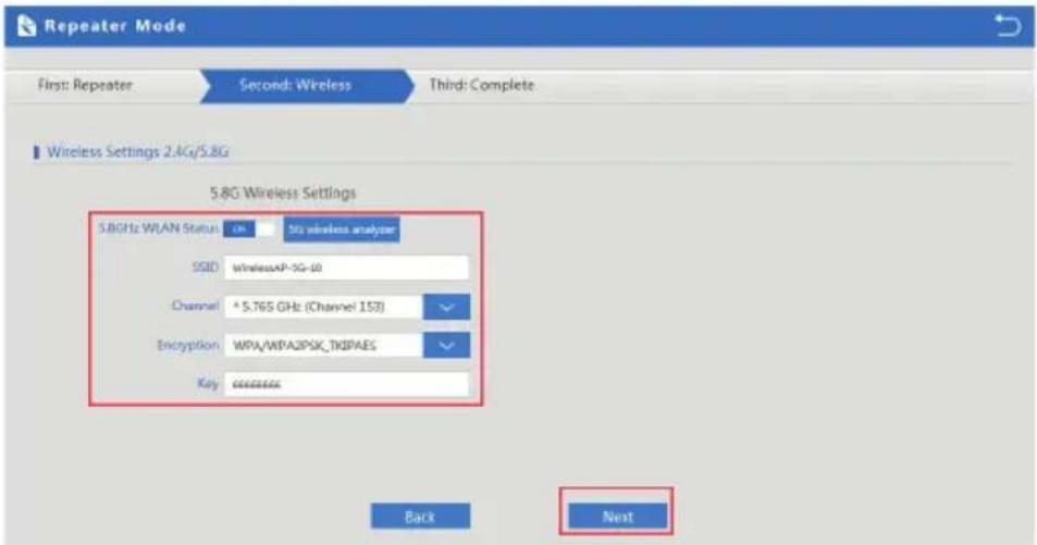
After click Next button, then should configure the wireless settig as follow, then click Next to finish:
Click Return button, will back to Status, show Repeater mode data, show fail or success, and user can configure this data in this page if required.
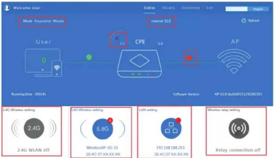
Note: When click wireless relay setting, following page will pop up, you can make change from here easy:

3.2.3 WISP Operation mode
Click WISP operation mode in Wizard, then will pop up the configure page, pls set the WISP operation mode based on the stepes showed in picture:

Configure the right WAN setting in WISP operation mode, then next.

Configure wireless data showed as follow:

Then complete and back to status, will show the connection fail or success, then can configure the data based on request:
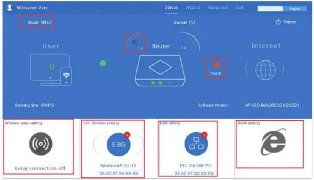
Remark: When click WAN Setting, will pop up following picture

3.2.4 AP operation mode
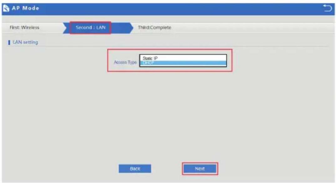
Set the wireless data, AP Location info as required, then click next to continue and enter into LAN setting.
After LAN setting, complete the AP mode configuration and back to Status:


3.3 Advanced Setting
In advanced setting, user can check the ceiling AP's firmware version, working status, 2.4G wireless, 5.8G Wireless, LAN Status, upgrade firmware, Reset Let's Click Advanced Setting in status page, will show return home, Setup Wizard which we showed before. Let's shown mode in Device Status, 2.4G Wireless, 5.8G Wireless, Network and Management.
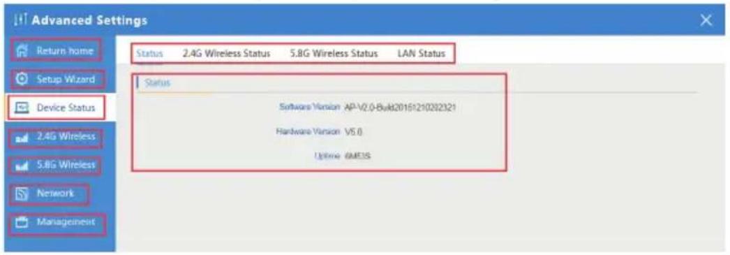
Device Status: : In this page, mainly to check the ceiling AP's status in firmware version, 2.4G Wireless, 5.8G Wireless and LAN status
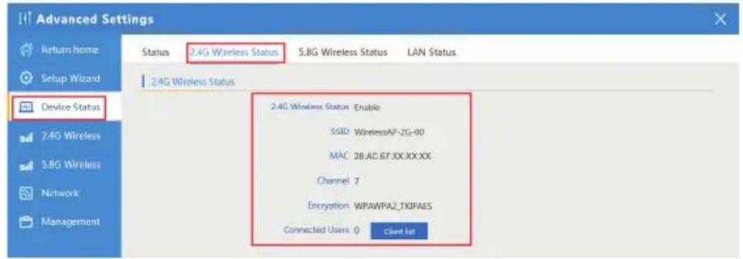


2.4G Wireless Setting: In this part, will show the 2.4G Basic Setting, Virtual AP, Access control and Advanced Setting
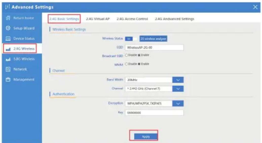
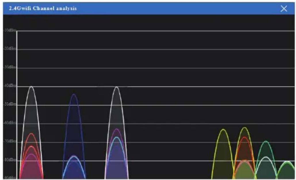
2G Wireless Analyzer: Mainly to analyze the AP's singal strength in some channel, to make user more easy to choose the right channel and avoid the wifi interface.
Virtual AP: There are 3 virtual AP in 2.4G wireless, if need virtual SSID, then users can configure it showed in following picture

2.4G Access Control: Mainly show MAC allow or deny

2.4G Advanced Settings: In this page, will show the regional, RF Power, Max user access.

5.8G Wireless Setting: Almost same as 2.4G Wireless

Network setting: In this page, mainly to show the LAN setting and VLAN as follow
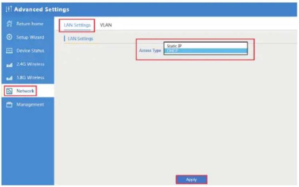

Management: In this part, show the system time, Logs, upgrade firmware, system, user info. And we show System time, how to upgrade firmware and system page to users


CHAPTER4
SHARE INTERNET AND OBTAIN IP ADDRESS AUTOMATICALLY
Set computer's TPC/IP as Obtain an IP address automatically, Obtain DNS server address automatically as following picture showed. the computer will obtain the IP address from router or base station to get Internet.

CHAPTER5
TROUBLE SHOOTING
| Failure phenomenon Solution | |
| SYS Indicator off | Pls make sure the PoE module connection is right. POE Port connect with AP, LAN port connect with computer |
| Can't land to Wireless AP through Web page | Pls check the IP address of computer and Wireless AP to see whether they are in same networking segment. The method is click "start" - "Run" input "cmd", ping 192.168.188.253 to test the Wireless AP con- nectivity;Reset Wireless AP and load it again;Pls make sure the IP address 192.168.188.253 is not occupied by other device in Wireless AP's networking;Check computer and cable problem, recom- mend to use 10/100M UTP unshielded cable; Clean up Arp binding from "Start" - "Run" input "cmd" arp -d Clean the IE Brower's tem-porary files and Cache file |
| Wireless AP can't connect with AP(the status display unconnected) | Try to scan the avaliable wireless networking again;Make sure the Wireless AP's wireless standard [11b/g/n, 2.4G] is correct;The Security and passwords are matched between Wireless AP and AP;The signal strength of AP is too weak to con- necl, should be more than -75dBm |
| Can't scan the wireless AP | Scan it several times more;Make sure there are 5G signal existed. Reset the Wireless AP, scan it again after Wireless AP restart; |
| The connection of Wireless AP and AP is success, but the computer can't share interne | Pls Check the computer's IP address and DNS setting. If it is dynamin, set the network card as automatically obtain. If it is static IP, pls contact with ISP for correct IP address and DNS address. |
| How to Reset Wireless AP | Press the "Reset" button more than 15 seconds after power on. The Wireless AP will restore factory default after the Wireless AP restart. |
CHAPTER 6
DECLARATION OF CONFORMITY

RoHS
It is stated that the construction materials used in our products comply with the requirements of Directive 2011/65 / EU (RoHS).

CE
Declaration of Conformity
Compliance with European Directives
The product complies with the requirements of the Low Voltage Directive (Safety) 2014/35 / EU and subsequent amendments.

Disposal of the Product
The product can not be disposed of as urban waste, but it must be collected separately; Any violation shall be punishable by monetary sanctions in accordance with current regulations.
Improper disposal of the product, or misuse of the product itself or parts thereof, is harmful to the environment and to human health.
Correct disposal of the products bearing the symbol of the bin marked by a cross helps to avoid possible negative consequences for the environment and huma
- WIRELESS ACCESS POINT DUAL BAND 750MBPS WL-ICDBG24-073
- THANKS
- FOR CHOSEN OUR PRODUCT
- INDEX
- CHAPTER 1 HARDWARE AND OPERATION MODE INSTRUCTION
- CHAPTER 2 LOGIN
- CHAPTER 3 WEB GUI INTERFACE SETTING
- CHAPTER 4 SHARE INTERNET AND OBTAIN IP ADDRESS AUTOMATICALLY
- CHAPTER 5 TROUBLE SHOOTING
- CHAPTER 6 DECLARATION OF CONFORMITY
- CHAPTER1
- HARDWARE AND OPERATION MODE INSTRUCTION
- 1.1 LED INDICATOR
- 1.2 AP INTERFACE
- 1.3 POWER SUPPLY
- 1.3.1 POE ADAPTER POWER SUPPLY
- 1.3.2 POWERED BY POE SWITCH
- 1.3.3 CONNECT WIRELESS AP WITH PC
- NOTE
- CHAPTER3
- WEB GUI INTERFACE SETTING
- 3.1 STATUS
- 3.2 WIZARD CONFIGURATION
- 3.2.1 GATEWAY MODE
- 3.2.2 WIFI REPEATER MODE
- 3.2.3 WISP OPERATION MODE
- RDS 40 DBM EXCHANGE: WPA/WPA/SPS/NSRMS
- 3.2.4 AP OPERATION MODE
- 3.3 ADVANCED SETTING
- CHAPTER4
- SHARE INTERNET AND OBTAIN IP ADDRESS AUTOMATICALLY
- CHAPTER5
- TROUBLE SHOOTING
- CHAPTER 6
- DECLARATION OF CONFORMITY
- ROHS
- CE
- DISPOSAL OF THE PRODUCT
Brand : Mach Power
Model : WL-ICDBG24-073
Category : Access Point