
Rdv2020 - Radio ZEBRA - Free user manual and instructions
Find the device manual for free Rdv2020 ZEBRA in PDF.


| Product Type | Two-Way Business Radio |
| Brand | Zebra |
| Model | Rdv2020 |
| Frequency Band | VHF (150.8 - 160 MHz) |
| Transmit Power | 2 Watts (selectable 1W or 2W) |
| Number of Channels | 2 |
| Antenna | Non-removable |
| Battery Type | Rechargeable Lithium-Ion (Standard, High, or Ultra High capacity) |
| Battery Life (Standard Li-Ion, Battery Save ON) | Up to 12 hours (2W transmit/receive/standby 5/5/90 duty cycle) |
| Charging Time (Standard Charger) | 7 hours for Standard battery, 12 hours for High capacity, 13 hours for Ultra High |
| Charging Time (Rapid Charger) | 1.5 hours for Standard, 3 hours for High, 3.5 hours for Ultra High |
| Operating Temperature | Below 50°F to above 95°F (10°C to 35°C) for charging |
| Talk Range (Indoor/Outdoor) | Up to 300,000 sq. ft. (VHF 2W) inside steel/concrete buildings; up to 18 floors in multi-level buildings |
| Key Features | VOX (hands-free with compatible accessories), Scan, Monitor, CTCSS/DPL codes, Scramble, Programmable buttons, Cloning, Battery Save, Time-Out Timer, Power Select, Roger Beep |
| Programming | Front panel programming for frequencies, codes, and auto-scan; or via CPS software (downloadable free) with optional programming cable |
| LED Indicators | Power-up red, transmit red heartbeat, receive red heartbeat, low battery orange, scan red heartbeat, etc. |
| Audio Accessories | Compatible with headsets, remote speaker microphones, earpieces (see Accessories list) |
| Safety & RF Exposure | Occupational use only; comply with FCC RF exposure requirements; read Product Safety booklet |
| Care & Cleaning | Wipe with soft damp cloth; do not immerse in water; do not use alcohol or cleaning solutions |
| Warranty | 1 year from date of purchase for products and accessories (batteries covered for capacity below 80%) |
Frequently Asked Questions - Rdv2020 ZEBRA
User questions about Rdv2020 ZEBRA
0 question about this device. Answer the ones you know or ask your own.
Ask a new question about this device
Download the instructions for your Radio in PDF format for free! Find your manual Rdv2020 - ZEBRA and take your electronic device back in hand. On this page are published all the documents necessary for the use of your device. Rdv2020 by ZEBRA.
USER MANUAL Rdv2020 ZEBRA
models RDU2020, RDV2020, RDU4100 and RDV5100
Radio models shown are RDU2020 and RDV2020
CONTENTS
Contents.... 1
Safety 4
Introduction ....5
Package Contents ....5
Batteries and Chargers
Safety Information ....7
Operational Safety Guidelines.....8
FCC Licensing Information .....9
Interference Information .....9
Radio Overview .....11
Parts of the Radio .....11
On/Off/Volume Knob.....12
Channel Selector Knob .....12
Accessory Connector .....12
Model Label 12
Microphone .....12
Antenna....12
LED Indicator 12
Side Buttons 12
The Lithium-Ion (Li-Ion) Battery ..... 12
Battery Features....14
About the Li-Ion Battery 14
Battery Recycling and Disposal ..... 15
Installing the Lithium-Ion
(Li-Ion) Battery 16
Removing the Lithium-Ion
(Li-Ion) Battery 16
Alkaline Battery Pack (Optional Accessory)....17
Installing Alkaline Batteries ..... 17
Removing Alkaline Batteries ..... 17
Attaching and Removing Antenna ..... 18
Attaching the Antenna 18
Removing the Antenna 18
Installing Spring Action Belt Clip ..... 19
Power Supply, Adaptor and Drop-in Tray Charger. 19
Battery Life Information ..... 20
Alkaline Battery Life 21
Charging the Battery 22
Getting Started .....29
Turning radio ON/OFF....29
Adjusting Volume .....29
Selecting a Channel .....29
Talking and Monitoring .....29
Receiving a Call ....30
Talk Range 30
Radio LED Indicators .....32
Hands-Free Use/VOX ....33
With Compatible VOX Accessories. . . . .33
Setting VOX Sensitivity .....34
Microphone Gain. 34
Battery Save ....34
Reset to Factory Defaults .....34
End of Transmission Tone (Roger Beep Tone)....35
Programming Features ....36
Programming Mode.....36
Learning to Read the Values the Radio Signals You ....36
Entering Programming Mode .....39
Reading Frequencies Values .....39
Reading CTCSS/DPL Values ..... 40
Reading Auto-Scan Values ..... 41
Programming Frequencies, Codes and Auto-Scan .... 41
Programming Mode FAQ....42
Programming Values Example. 43
Example of Programming a Frequency....43
Example of Programming a Code 44
Example of Programming Auto-Scan 45
Other Programming Features ..... 46
Scan. 46
Editing Scan List 47
Nuisance Channel Delete 47
CPS (Computer Programming Software) . . . 48
Time-Out Timer 49
Power Select 49
Battery Type Setting 49
Call Tones 49
Scramble 50
Reverse Burst 50
Cloning Radios .....51
Cloning with a Multi
Unit Charger (MUC) .....51
Cloning Radio using
the Radio to Radio (R2R) Cloning
Cable (Optional Accessory) .....53
Cloning using the CPS (Computer
Programming Software) .....55
Troubleshooting ....56
Use and Care 60
Frequency and Code Charts .....61
RDX VHF Frequencies Chart .....61
RDV2020 - VHF
Default Frequencies Chart ....63
RDV5100 - VHF
Default Frequencies Chart .....64
RDX UHF Frequencies Chart .....65
RDU2020 - UHF
Default Frequencies Chart .....69
RDU4100 - UHF
Default Frequencies Chart ....70
CTCSS and PL/DPL Codes ..... 71
Programming Customized Frequencies on 4W/5W RDX models ..... 75
Motorola Limited Warranty for the United States and Canada 76
Accessories 80
Antennas 80
Audio Accessories 80
Battery 80
Carry Accessories 81
Power Supplies AC Pin Adaptors....81
Software Applications....81
Cables 81
Chargers 81
Power Supplies 82
RDX Series™ Features Summary ..... 83
Programmable Buttons Chart .....93
Icons Chart 94
SAFETY
PRODUCT SAFETY AND RF EXPOSURE COMPLIANCE

Before using this product, read the operating instructions and RF energy awareness information contained in the Product Safety and RF Exposure booklet enclosed with your radio.
ATTENTION!
This radio is restricted to occupational use only to satisfy FCC RF energy exposure requirements.
For a list of Motorola-approved antennas, batteries, and other accessories, visit the following website which lists approved accessories:
www.motorolasolutions.com/RDX
English
INTRODUCTION
Thank you for purchasing the Motorola® RDX Series™ Radio. This radio is a product of Motorola's 75 plus years of experience as a world leader in the designing and manufacturing of communications equipment. The RDX Series™ radios provide cost-effective communications for businesses such as retail stores, restaurants, schools, construction sites, manufacturing, property and hotel management and more. Motorola Business two-way radios are the perfect communications solution for all of today's fast-paced industries.
Note: Read this user guide carefully to ensure you know how to properly operate the radio before use
Business Radios,
RPSD 1C15, Motorola
8000 West Sunrise Boulevard
Plantation, Florida 33322
PACKAGE CONTENTS
- Radio
• Antenna (only for RDU4100 and RDV5100) - Spring Action Belt-Clip
- Lithium-Ion Battery
- Power Supply
- User Guide
- Warranty Card
- Drop-in Tray Charger
• Product Safety & RF Exposure Booklet
For a copy of a large-print version of this user guide or for product-related questions, contact:
1-800-448-6686 in the USA
1-800-461-4575 in Canada
1-866-522-5210 on your TTY (Text Telephone)
For product information visit us at:
www.motorolasolutions.com/RDX
BATTERIES AND CHARGERS SAFETY INFORMATION
This document contains important safety and operating instructions. Read these instructions carefully and save them for future reference.
Before using the battery charger, read all the instructions and cautionary markings on
- the charger,
-
the battery, and
• the radio using the battery -
To reduce risk of injury, charge only the rechargeable Motorola-authorized batteries. Other batteries may explode, causing personal injury and damage.
-
Use of accessories not recommended by Motorola may result in risk of fire, electric shock, or injury.
-
To reduce risk of damage to the electric plug and cord, pull by the plug rather than the cord when disconnecting the charger.
- An extension cord should not be used unless absolutely necessary. Use of an improper extension cord could result in risk of fire and electric shock. If an extension cord must be used, make sure that the cord size is 18AWG for lengths up to 6.5 feet (2.0 m), and 16AWG for lengths up to 9.8 feet (3.0 m).
- To reduce risk of fire, electric shock, or injury, do not operate the charger if it has been broken or damaged in any way. Take it to a qualified Motorola service representative.
- Do not disassemble the charger; it is not repairable and replacement parts are not available. Disassembly of the charger may result in risk of electrical shock or fire.
- To reduce risk of electric shock, unplug the charger from the AC outlet before attempting any maintenance or cleaning
OPERATIONAL SAFETY GUIDELINES
- Turn the radio OFF when charging battery.
- The charger is not suitable for outdoor use. Use only in dry locations/conditions.
- Connect charger only to an appropriately fused and wired supply of the correct voltage (as specified on the product).
-
Disconnect charger from line voltage by removing main plug.
-
The outlet to which this equipment is connected should be nearby and easily accessible.
- Maximum ambient temperature around the power supply equipment must not exceed 40°C (104°F).
- Make sure that the cord is located where it will not be stepped on, tripped over, or subjected to water, damage, or stress.
FCC LICENSING INFORMATION
INTERFERENCE INFORMATION
This device complies with Part 15 of the FCC Rules. Operation is subject to the condition that this device does not cause harmful interference.
RDX Series™ Business two-way radios operate on radio frequencies that are regulated by the Federal Communications Commission
(FCC). To transmit on these frequencies, you are required to have a license issued by the FCC. Application is made available on FCC Form 601 and Schedules D, H, and Remittance Form 159.
To obtain these FCC forms, request document 000601 which includes all forms and instructions. If you wish to have the document faxed, mailed or have questions, use the following contact information.
| Faxed contact the Fax-On- Demand system at: | Mailed call the FCC forms hotline at: | Questions regarding FCC license contact the FCC at: |
| 1-202-418-0177 1-800-418-FORM1-800-418-3676 | 1-800-418-3676 | 1-888-CALL-FCC1-888-225-5322Or: http://www.fcc.gov |
Before filling out your application, you must decide which frequency(ies) you can operate on. See “Frequencies and Code Charts”. For questions on determining the radio frequency, call Motorola Product Services at:
1-800-448-6686
Changes or modifications not expressly approved by Motorola may void the user's authority granted by the FCC to operate this radio and should not be made. To comply with FCC requirements, transmitter adjustments should be made only by or under the supervision of a person certified as technically qualified to perform transmitter maintenance and repairs in the private land mobile and fixed services as certified by an organization representative of the user of those services.
Replacement of any transmitter component (crystal, semiconductor, etc.) not authorized by the FCC equipment authorization for this radio could violate FCC rules.
Use of this radio outside the country where it was intended to be distributed is subject to government regulations and may be prohibited
RADIO OVERVIEW
PARTS OF THE RADIO


On/Off/Volume Knob
Used to turn the radio ON or OFF and to adjust the radio's volume.
Channel Selector Knob
Used to switch the radio to different channels.
Accessory Connector
Used to connect compatible audio accessories.
Model Label
Indicates the model of the radio.
Microphone
Speaks clearly into the microphone when sending a message.
Antenna
For models RDU2020, and RDV2020 the antennas are non-removable. For RDV5100, RDU4100 antennas are removable.
LED Indicator
Used to give battery status, power-up status, radio call information and scan status.
English
Side Buttons
Push-to-Talk (PTT) Button
- Press and hold down this button to talk, release it to listen.
Side Button 1 (SB1)
- The Side Button 1 is a general button that can be configured by the Computer Programming Software - CPS. The default setting of SB1 is 'Monitor'.
Side Button 2 (SB2)
- The Side Button 2 is a general button that can be configured by the CPS. The SB2 default setting is 'Scan/Nuisance Channel Delete'.
The Lithium-Ion (Li-Ion) Battery
RDX Series™ provides different types of batteries. For more information, see “Battery Features” on page 14.
This User Guide covers multiple RDX Series™ models, and may detail some features your radio does not have. The radio's model is shown on the front of the radio, underneath the
speaker, and provides you the following information:
| Model | Frequency Band | Transmit Power (Watts) | Number of Channels | Antenna |
| RDV2020 VHF | 2 2 Non-removable | |||
| RDU2020 UHF | 2 2 Non-removable | |||
| RDU4100 UHF | 4 10 removable | |||
| RDV5100 | VHF | 5 | 10 | removable |
BATTERY FEATURES
RDX Series™ radios provide Lithium-Ion batteries that come in different capacities that will define the battery life. It also offers the option to use Alkaline batteries.
About the Li-Ion Battery
The RDX Series ™ radio comes equipped with a rechargeable Li-Ion battery. This battery should be charged before initial use to ensure optimum capacity and performance.
Battery life is determined by several factors. Among the more critical are the regular overcharge of batteries and the average depth of discharge with each cycle. Typically, the greater the overcharge and the deeper the average discharge, the fewer cycles a battery will last. For example, a battery which is overcharged and discharged 100% several times a day, lasts fewer cycles than a battery that receives less of an overcharge and is discharged to 50% per day. Further, a battery
which receives minimal overcharging and averages only 25% discharge, lasts even longer.
Motorola batteries are designed specifically to be used with a Motorola charger and vice versa. Charging in non-Motorola equipment may lead to battery damage and void the battery warranty. The battery should be at about 77° F ( 25° C) (room temperature), whenever possible. Charging a cold battery (below 50° F [ 10° C]) may result in leakage of electrolyte and ultimately in failure of the battery. Charging a hot battery (above 95° F [ 35° C]) results in reduced discharge capacity, affecting the performance of the radio. Motorola rapid-rate battery chargers contain a temperature-sensing circuit to ensure that batteries are charged within the temperature limits stated above.
Battery Recycling and Disposal
Li-Ion rechargeable batteries can be recycled. However, recycling facilities may not be available in all areas. Under various U.S. state laws and the laws of several other countries, batteries must be recycled and cannot be disposed of in landfills or incinerators. Contact your local waste management agency for specific requirements and information in your area. Motorola fully endorses and encourages the recycling of Li-Ion batteries. In the U.S. and Canada, Motorola participates in the nationwide Rechargeable Battery Recycling Corporation (RBRC) program for Li-Ion battery collection and recycling. Many retailers and dealers participate in this program. For the location of the drop-off facility closest to you, access RBRC's Internet web site at:
www.rbrc.com
or call:
1-800-8-BATTERY
This internet site and telephone number also provides other useful information concerning recycling options for consumers, businesses and governmental agencies.
Installing the Lithium-Ion (Li-Ion) Battery

- Turn OFF the radio.
- With the Motorola logo side up on the battery pack, fit the tabs at the bottom of the battery into the slots at the bottom of the radio's body.
- Press the top part of the battery towards the radio until a click is heard.
Note: To learn about the Li-Ion Battery Life features, refer to "About the Li-Ion Battery" on page 14
Removing the Lithium-Ion (Li-Ion) Battery
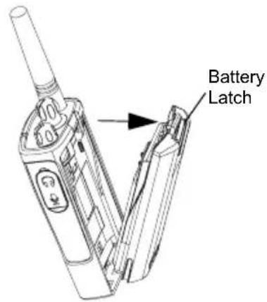
- Turn OFF the radio.
- Push down the battery latch and hold it depressed while removing the battery.
- Pull the battery away from the radio.
Alkaline Battery Pack (Optional Accessory) Installing Alkaline Batteries
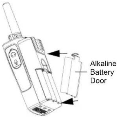
- Turn OFF the radio, if it is turned ON.
- Remove Li-Ion battery.
- Assemble alkaline battery pack in the same steps as installing the Li-Ion battery pack.
- Remove battery door from alkaline battery pack.
- Slide the 5 AA alkaline batteries into the frame, matching the markings inside the compartment
Removing Alkaline Batteries
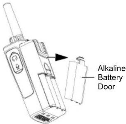
- Turn OFF the radio, if it is turned ON.
- Slide the battery latches, on both sides of the battery, downwards.
- Pull the top of the battery away from the radio's body, and lift the battery from the radio's body.
Attaching and Removing Antenna
These instructions apply ONLY to models RDU4100 and RDV5100. Do not attempt to remove the antenna if your radio is not one of these models.
Attaching the Antenna
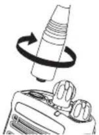
-
Align the threaded end of the antenna with the radio's antenna connector.
-
Turn the antenna clockwise to fasten it.
Removing the Antenna

- Turn the antenna counterclockwise until you can remove it.
Installing Spring Action Belt Clip

- Slide the spring action belt clip rails into the belt clip grooves on the back of the battery pack and slide it down until the belt clip tab snaps into place.
- To remove, pull back the metal release tab on the belt clip tab and push the spring action belt clip upward to remove.
Power Supply, Adaptor and Drop-in Tray Charger

The radio is equipped with one Drop-in Tray Charger and one Power Supply with Adaptor. For details, see "Chargers" on page 81.
Battery Life Information
When the Battery Save feature is ON (enabled by default) the battery life will be longer. The following chart summarizes battery life estimations:
| Li-Ion Battery Life with Battery Save feature ON | |||
| Battery Type 5 Watts | 4 Watts 2 Watts | ||
| Standard 8.5 hours 8.5 hours | 12 hours | ||
| High 17 hours 17 hours 24 hours | |||
| Ultra High 18.5 hours 18.5 hours | 26 hours | ||
Note: Battery life is estimated based on 5% transmit/ 5% receive/ 90% standby standard duty cycle
Alkaline Battery Life
The following chart estimates the Alkaline battery life:
| Alkaline Battery Life | |||
| Battery Save Feature | 5 Watts | 4 Watts | 2 Watts |
| ON 26 hours* 26 hours* 26 hours | |||
Notes:
- Battery life are being estimated based on 5% transmit/ 5% receive/ 90% standby standard duty cycle.
- * When using Alkaline battery, the radio is set to 2W by default
Charging the Battery
RDX Series™ offers two types of chargers :
- Standard Charger and,
- Rapid Charger.
Note: The radio comes equipped with a Standard Charger
To charge the battery (with the radio attached), place it in a Motorola-approved Drop-in Tray Single Unit Charger or Drop-in Tray Multi Unit Charger.
Note: When acquiring additional chargers or power supplies, make sure you have similar drop-in tray chargers and power supplies sets (all "rapid" or all "standard"). For part number details, refer to "Chargers" on page 81
Charging with the Drop-in Tray Single Unit Charger (SUC)
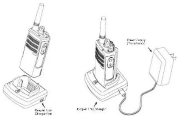
- Place the drop-in tray charger on a flat surface.
- Insert the connector of the power supply into the port on the side of the drop-in tray charger.
- Plug the AC adaptor into a power outlet.
- Insert the radio into the tray with the front of the radio facing the front of the charger, as shown.
Note: When charging a battery attached to a radio, turn the radio OFF to ensure a full charge. See "Operational Safety Guidelines" on page 8 for more information
Charging a Standalone Battery

To charge only the battery - at step 4, insert the battery into the tray, with the inside surface of the battery facing the front of the charger, as shown. Ensure the slots in the battery correctly engage in the charger
Note: Ensure that the bracket in the charger is adjusted to the correct position for either Standard or High capacity battery. See "Charging a Standard Battery" on page 23
Charging a Standard Battery
The drop-in tray charger has a removable bracket that is adjustable depending on the type of battery that needs to be charged. It is designed to charge either the battery (with the radio) or a standalone battery. The drop-in tray charger's default position will charge a standard battery. The following image shows the orientation for each battery:
Adjustable bracket
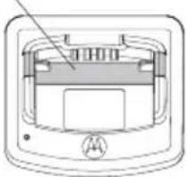
Standard
Adjustable bracket

High and Ultra High Capacity
Figure 1: Identifying the Drop-In Charger's Position Before Charging the Battery
Charging a High Capacity or Ultra High Capacity Battery

To convert the charger from the default setup to accommodate the High capacity or Ultra High capacity battery:
- Squeeze both tabs on each side of the removable bracket in the drop-in charger tray and lift the bracket from the charger tray.
-
Rotate the removable bracket 180 degrees and replace it by fitting it in the charger slot until it snaps. The label on the removable bracket should show 'High & Ultra Capacity Battery' facing front of the charger.
-
Repeat same procedure to return to the charging a Standard Battery position. Label on the removable bracket should show 'Standard Battery' facing front.
Note: Make sure the bracket is assembled correctly for both standalone battery and battery (with radio)
English
Drop-in Tray Charger LED Indicators
| Standard Charger LED Indicator | ||
| Status LED | Status Comments | |
| Power ON | Steady red indication for 3 seconds | The charger has powered up |
| Charging Blinking | red (slow) The charger is currently charging | |
| Charging Complete | Steady red indication Battery is fully charged | |
| Battery Fault(*) | Blinking red (fast) | Battery had a fault when battery was inserted |
Notes:
- (*) Normally re-seating the battery pack will correct this issue.
- (**) Battery temperature is too warm or too cold or wrong power supply is being used
Rapid Charger LED Indicator
| Status LED | Status Comments | |
| Power ON | Steady green indication for 3 seconds | The charger has powered up |
| Charging Blinking | green The charger is currently charging | |
| Top-off Charging | Blinking green (slow) | Battery is near fully charged |
| Charge Complete | Steady green indication Battery is fully charged | |
| Battery Fault (*) | Blinking red (fast) | Battery has a fault when battery was inserted |
| Waiting to Charge (**) | Double-blink yellow indications | Battery charging conditions not suitable |
Notes:
- (*) Normally re-seating the battery pack will correct this issue.
- (**) Battery temperature is too warm or too cold or wrong power supply is being used
Estimated Charging Time
The following table provides the estimated charging time of the battery. For further details, see "Battery" on page 80.
| Estimated Charging Time | |||
| Charging Solution | Battery Type | ||
| Standard High Capacity | Ultra High Capacity | ||
| Standard Charging Solution | 7 hours 12 hours 13 hours | ||
| Rapid Charging Solution | 1.5 hours 3 hours 3.5 hours | ||
Charging a Radio and Battery using a Multi Unit Charger- MUC (Optional Accessory)

The Multi Unit Charger (MUC) allows drop-in charging of up to 6 radios or batteries. Batteries can be charged with the radios or removed and placed in the MUC separately. Each of the 6 charging pockets can hold a radio or battery, but not both.
- Place the charger on a flat surface.
- Insert the power cord plug into the MUC's jack.
- Plug the cord into an AC outlet.
- Turn the radio OFF.
- Set removable bracket for battery type.
- Insert the radio or battery into the charging pocket.
Notes:
- This Multi Unit Charger also allows you to clone up to 3 radios (3 Source radios and 3 Target radios). Refer to page 51 for details.
- Further details on MUC's operation are explained in the Instructions Sheet provided with the MUC. For part number details, refer to the Accessories section.
MUC LED Indicator
| Status LED Status Comments | ||
| Charging | Steady Red Indication | The charger is currently charging |
| Charge Complete | Steady Green Indication | Battery is fully charged |
| Battery Fault (*) | Blinking red (fast) | Battery was faulty when inserted |
Note: (*) Normally re-seating the battery pack will correct this issue.
GETTING STARTED
For the following explanations, refer to “Parts of the Radio” on page 11.
To turn ON the radio, rotate the On/Off/Volume Knob clockwise. The radio will chirp and the LED Indicator will briefly blink red.
To turn the radio OFF, rotate the On/Off/Volume Knob counterclockwise until you hear a 'click' and the radio LED Indicator turns OFF.
ADJUSTING VOLUME
Turn the On/Off/Volume Knob clockwise to increase the volume, or counterclockwise to decrease the volume.
Note: Do not hold the radio too close to the ear when the volume is high or when adjusting the volume
SELECTING A CHANNEL
To select a channel, rotate the Channel Selector Knob and select the desired channel number.
Program each channel separately. Each channel has its own Frequency, Interference Eliminator Code and Scan Settings.
TALKING AND MONITORING
It is important to monitor for traffic before transmitting to avoid ‘talking over’ someone who is already transmitting
To monitor, long press and hold the SB1(*) button to access channel traffic. If no activity is present, you will hear 'static'. To release, press SB1 again. Once channel traffic has cleared, proceed with your call by pressing the PTT button. When transmitting, the LED Indicator will blink red every 3 seconds.
Notes:
- To listen to all activity on a current channel, short press the SB1 to set the CTCSS/DPL code to 0. This feature is called 'CTCSS/DPL Defeat (Squelch set to SILENT)'.
• (*) This assumes SB1 is not being programmed for a different mode.
RECEIVING A CALL
- Select a channel by rotating the Channel Selector Knob until you reach the desired channel.
- Make sure the PTT button is released and listen for voice activity.
- The LED Indicator blinks red while the radio is receiving a call.
- To respond, hold the radio vertically 1 to 2 inches (2.5 to 5cm) from mouth. Press the PTT button to talk; release it to listen.
TALK RANGE
| TALK RANGE | ||
| Model | Industrial Multi-Level | |
| Inside steel/concrete Industrial buildings | Inside multi-level buildings | |
| UHF 4W | Up to 350,000 Sq. Ft. Up | to 30 Floors |
| VHF 5W | Up to 300,000 Sq. Ft. Up | to 18 Floors |
| UHF 2W | Up to 250,000 Sq. Ft. Up | to 20 Floors |
| VHF 2W | Up to 220,000 Sq. Ft. Up | to 13 Floors |
To establish a proper two-way communication, the channel, frequency, and interference eliminator codes must be the same on both radios. This depends on the stored profile that has been preprogrammed on the radio:
- Channel: Current channel that the radio is using, depending on radio model.
- Frequency: The frequency the radio uses to transmit/receive.
-
Interference Eliminator Code: These codes help minimize interference by providing a choice of code combinations.
-
Scramble Code: Codes that make the transmissions sound garbled to anyone listening who is not set to that specific code.
For details on how to set up frequencies and CTCSS/DPL codes in the channels, refer to "Programming Selection Mode" in page 36.
RADIO LED INDICATORS
| RADIO STATUS LED INDICATION | |
| Channel Alias Edit Red heartbeat | |
| Channel Busy Solid orange | |
| Cloning Mode Two orange heartbeats | |
| Cloning In Progress Solid orange | |
| Fatal Error at Power up | One green blink, one orange blink, one green blink, then repeat for 4 seconds |
| Low Battery Orange blink | |
| Low Battery Shutdown Orange heartbeat | |
| Monitor LED is OFF | |
| Power-Up Solid red for 2 seconds | |
| ‘Idle’ Programming Mode / Channel Mode | Green heartbeat |
| Scan Mode Red heartbeat | |
| Transmit (Tx)/Receive (RX) Red heartbeat | |
| Transmit in Low Power Select | Orange heartbeat |
Note: Channel Alias Edit only applies to Display Models
English
HANDS-FREE USE/VOX

Motorola RDX Series™ radios can operate hands-free (VOX) when used with compatible VOX accessories.
With Compatible VOX Accessories
The default factory setting for VOX sensitivity level is OFF (level '0'). Before using VOX, set VOX level to a level different from '0' via the CPS. Then, perform the following steps:
- Turn the radio OFF.
- Open accessory cover.
- Insert the audio accessory's plug firmly into accessory port.
- Turn radio ON. The LED Indicator will blink double red
- Lower radio volume BEFORE placing accessory near ear.
- To transmit, speak into accessory microphone and to receive, stop talking.
- VOX can be temporarily disabled by pressing the PTT button or by removing the audio accessory.
Note: To order accessories, refer to: www.motorolasolutions.com, call 1 (800) 448-6686, or contact your Motorola point of purchase
Setting VOX Sensitivity
The sensitivity of the radio's accessory or microphone can be adjusted to suit different operating environments. VOX sensitivity can be programmed via the CPS.
Default value is OFF (level 0). If you want to use the VOX feature, VOX level should be set at a level different from 0.
- 1 = Low sensitivity
- 2 = Medium sensitivity
• 3 = High sensitivity
Microphone Gain
The sensitivity of the microphone can be adjusted to fit different users or operating environments.
This feature can be adjusted only through the CPS. Microphone default setting is set to level 2 (medium gain).
Battery Save
Battery Save feature extends battery life as your radio goes into 'Idle' state. To enable/disable press SB1 and SB2 buttons simultaneously for 2 or 3 seconds while powering up the radio until you hear a quick series of beeps. To have a slightly better attack time, set Battery Save feature to OFF so that the radio is always ready to transmit or receive without any delays.
Note: Battery Save feature is set to ON by default
Reset to Factory Defaults
Reset to Factory Defaults will set back all radio features to the original factory default settings. To do so, press PTT, SB2 and SB1 simultaneously while turning ON the radio until you hear a high tone chirp.
End of Transmission Tone (Roger Beep Tone)
To enable/disable End of Transmission Tone, short press the SB1 button while turning ON the radio.
Note: This setting is set to OFF by default
PROGRAMMING FEATURES
To easily program all the features in your radio, it is recommended to use the CPS
Programming Cable and CPS software.
CPS software download is available for free at www.motorolasolutions.com/RDX
PROGRAMMING MODE
Programming Mode is a special radio mode to program basic radio's features by using the radio's panel.
When the radio is set to Programming Mode, you are able to read and modify three features:
- Frequencies,
- Codes (CTCSS/DPL) and,
- Auto-Scan.
The Programming Frequencies feature allows you to select frequencies for each channel.
The Interference Eliminator Code (CTCSS/DPL) helps minimize interference by providing you with a choice of code combinations that filter out static, noise, and unwanted messages.
The Auto-Scan feature allows you to set a particular channel to automatically enable Scan each time you switch to that channel.
Learning to Read the Values the Radio Signals You
As the non-display model does not have a display to show the values that are being programmed, the radio will communicate this information using beeps and LED indications.
The radio's LEDs will blink two colors:
- Orange to signal '0' and,
- Red for other values from '1' to '9'.
Short and long red blinks differentiate the specific number the radio is signaling you.
Please refer to "Programming Mode: Reading the Values" table on page 38.
English
![graph TD A["1 Frequencies"] --> B["First Digit"] B --> C["Second Digit"] C --> D["PTT"] D --> E["2 CTCSS/DPL"] E --> F["First Digit"] F --> G["Second Digit"] G --> H["PTT"] H --> I["Third Digit"] I --> J["PTT"] J --> K["3 Auto - Scan"] K --> L["ON / OFF"] M["Idle Programming Mode"] --> N["PTT"] N --…](/content/2026/05/1072971/images/03355b34f2751cdfc252337591fedbedd6126da92043a1bbbf1c36d8910736a9.jpg)
Figure 1: Entering Programming Mode
Programming Mode: Reading the Values
| Number Confirmation Beep | LED Indication | |
| 0 | Zero beep One orange blink | |
| 1 | One beep One short red blink | |
| 2 | Two beeps Two short red blinks | |
| 3 | Three beeps Three short red blinks | |
| 4 | Four beeps Four short red blinks | |
| 5 | Long beep One long red blink | |
| 6 | Long beep and one beep One long and one short red blinks | |
| 7 | Long beep and two beeps One long and two short red blinks | |
| 8 | Long beep and three beeps One long and three short red blinks | |
| 9 | Long beep and four beeps | One long and four short red blinks |
Entering Programming Mode
Note: Before programming the features, make sure your radio is set to the channel you wish to program. You can do so before entering Programming Mode or at any time during the Programming Mode by turning the Channel Selector Knob to the desired channel
To read or modify Frequencies, Codes and Auto-Scan, set the radio to 'Programming Mode' by long pressing both the PTT and the SB1 button simultaneously while turning ON the radio for 3 to 5 seconds until a 'chirp' sounds to indicate that you have entered 'Idle' Programming Mode (*). The LED Indicator will start blinking a green heartbeat.
Note: (*)'Idle' Programming Mode is the stage of the Programming Mode in which the radio is waiting for the user to start the radio programming cycle (refer "Entering Programming Mode" on page 37)
Once you are in the 'Idle' Programming Mode, you will be able to read the Frequencies, Codes and Auto-Scan setting by short pressing the PTT button to move along the different programmable features.
Reading Frequencies Values
When reading frequencies values you need to read two digits as RDX Series™ radios have 27 frequencies for VHF and 89 frequencies for UHF.
Once in 'Idle' Programming Mode, the radio will signal the first value it was programmed when you short press the PTT button (see Figure 2: Reading Frequencies Values on page 40). This value corresponds to the frequency's first digit
value. If you short press the PTT button again, the radio will signal you the second digit value.
![graph TD A["First Digit"] -->|PTT| B["Second Digit"] B -->|PTT| C["Long PTT"] C --> D["PTT"] style A fill:#f9f,stroke:#333 style B fill:#f9f,stroke:#333 style C fill:#ccf,stroke:#333 style D fill:#cfc,stroke:#333](/content/2026/05/1072971/images/99f8abd4f1f4baaa61ce5b328c07458ba54115a2edef77e5641de3f32152f797.jpg)
Figure 2: Reading Frequencies Values
Reading CTCSS/DPL Values
If you continue short pressing the PTT button as shown in Figure 1: Entering Programming Mode on page 37 (stage 2), the radio will move forward to programming CTCSS/PL Codes.
When reading the values for CTCSS/PL Codes the radio signals you the digit codes each time you short press the PTT button.
You will have to read three digits as RDX Series™ have up to 213 codes available (refer to "Frequencies and Codes Charts" Section).
The following is an example of the order in which your radio will be signaling the '118' CTCSS/DPL code:
![graph TD A["First Digit"] --> B["1"] B --> C["Second Digit"] C --> D["1"] D --> E["8"] E --> F["Third Digit"]](/content/2026/05/1072971/images/a0e54c5bd75232c9ec85b24990d2dfd19150e9fdc9d1d42153c52e5a43189cc5.jpg)
Figure 3: Example of How to Program Values
- Short press the PTT button. The radio will signal you the first digit '1'.
- Short press PTT button again and the radio will show the second digit '1' and,
- Finally, short press PTT again and radio will show the third digit '8'.
Reading Auto-Scan Values
After reading the CTCSS/DPL codes, short press the PTT button and the radio will take you to Auto-Scan (refer to Stage 3 of Figure 3: Entering Programming Mode on page 40).
Auto-Scan only has two values:
| If the radio signals the value... | It means Auto-Scan is... |
| 0 | OFF |
| 1 | ON |
• Auto-Scan is set to OFF by default.
Note: While in Auto-Scan Mode, if you short press PTT button, the radio will return to the 'Idle' Programming Mode. It will then generate a 'roll-over' chirp and it will start blinking a green heartbeat
Programming Frequencies, Codes and Auto-Scan
Each time your radio signals and beeps the current setting you can change this setting by either increasing it by short pressing SB1 or decreasing it by short pressing SB2. The radio will then signal the new setting it has been programmed.
Saving Settings
If you are satisfied with the setting, you can either:
- short press PTT to continue programming,
- long press PTT to save and return to 'Idle' Programming Mode, or
- long press the PTT button twice to exit 'Idle' Programming Mode and return to the normal radio operation.
Note:
- If you do not wish to save the value you just programmed, turn radio OFF or change channel using the channel knob.
- If you ‘roll-over’ to the beginning at Idle Programming Mode you will hear a ‘chirp’ and the LED Indicator will start blinking green again. All values that were changed will be automatically saved.
Programming Mode FAQ
- I got distracted while programming and forgot which digit I was programming. What should I do?
Return to 'Idle' Programming Mode and start over, as you will not be able to return to the Programming Mode (the radio does not provide further way to let you know the specific stage you are at when programming). Therefore you can:
- Long press the PTT button. The radio will return to the 'Idle' Programming Mode or,
-
Turn OFF the radio and enter Programming Mode again (see instructions in the beginning of this section)
-
I am trying to program a frequency (or code) value but the radio would not do it. It rolled over and took me back to value '0'.
The radio will not allow you to program any values that are not available in the frequencies and codes pool. For example, if you try to program code 128, the radio would not accept it, as the maximum value allowed is 122. Same thing will happen with frequencies. Check the Frequencies and Codes Charts section to make sure you are programming a valid number.
- I am trying to enter the Programming Mode but the radio would not do it.
The radio might be locked using the CPS to not allow Front Panel Programming. To re-enable, use the CPS.
- When I was programming I made a mistake and programmed the wrong value. How can I erase it or re-program it?
If you make a mistake while programming a value you have two choices:
- The radio roll-over (and generates a 'wrap-around' sound) each time it reaches a maximum (9) or minimum (0) value. Keep increasing (short press SB1) or decreasing (short pressing SB2) until you get the desired value or,
- Turn OFF the radio and start-over.
- I just programmed the value I wanted. How do I exit Programming Mode?
- If you are in Programming Mode you can exit by long pressing the PTT button twice.
-
If you are already in the 'Idle' Programming Mode, long press the PTT button once.
-
I am done programming the features in this channel and want to program another channel.
Switch to the new channel you wish to program by using the Channel Selector Knob. The radio will enter 'Idle' Programming Mode. If you wish to save the changes, make sure you are in the 'Idle' Programming Mode before switching the channel as otherwise you will lose the changes made.
PROGRAMMING VALUES EXAMPLE
Example of Programming a Frequency
Assuming current frequency value is set to Channel 1, with the UHF default frequency '02' (equivalent to 464.5500 MHz), and you want to change it to Frequency Number = '13' (which is mapped to 461.1375 MHz), follow this sequence:
- Enter Programming Mode
- Short press the PTT button to enter Frequency Mode. Radio will signal current value '0' (orange blink)
- Press the SB1 button once to increase first digit to '1'.
- Short press the PTT button once to move ahead and program the frequency's second digit. Radio will signal current value which is '2' (two red blinks).
- Press the SB1 button to increase the digit value to '3'.
- Long press the PTT button. LED Indicator will show a green heartbeat to indicate 'Idle' state.
- Long press the PTT button to exit Programming Mode or turn radio OFF.
Example of Programming a Code
Assuming current code value is set to factory default '001', and you want to change it to CTCSS/DPL Code = 103 follow the sequence below:
- Enter Programming Mode
- Short press the PTT button three times (Enter CTCSS/DPL Programming Selection Mode). The LED Indicator will blink orange to indicate that current value is '0'
-
Press the SB1 button once (to change first digit to '1') LED Indicator will blink red. Short press the PTT button (to move forward and program second digit). The LED Indicator will blink orange to indicate current value is '0'.
-
Short press the PTT button and move ahead to program the third digit. LED Indicator will blink red to indicate current value is '1'.
- Press the SB1 button to change the 'third digit' to '2'. Press the SB1 button to change again this 'third digit' to '3'. Radio will signal the chosen value.
- Long press the PTT button to save changes and return to 'Idle' Programming Mode.
- Once in 'Idle' Programming Mode, LED Indicator will start blinking a green heartbeat.
- Long press the PTT button to exit Programming Mode.
Example of Programming Auto-Scan
Auto-Scan is the last Programming Mode and can be set to either ON or OFF on a particular channel.
To set Auto-Scan to ON:
- Enter Programming Mode and select the desired channel (see Figure 1: Entering Programming Mode on page 37).
- Short press the PTT button six times to enter Auto-Scan Programming Selection Mode. The radio will signal beeps and will show the current Auto-Scan setting (please refer to “Reading Auto-scan Settings” on page 41).
- Short press the SB1 button to toggle ON/OFF the Auto-Scan feature in the channel. When ON, the LED Indicator will blink RED once. When OFF, the LED Indicator will blink ORANGE once.
OTHER PROGRAMMING FEATURES
Scan
Scan allows you to monitor other channels to detect conversations. When the radio detects a transmission, it will stop scanning and will stop on the active channel. This will allow you to listen and talk to people on that channel without having to change the channel knob. If there is talking on Channel 2 during this time, the radio will stay on Channel 1 and you will not hear Channel 2. After talking has stopped in Channel 1, the radio waits for 5 seconds before resuming scan again.
- To start scanning, press the SB2 button (*). When the radio detects channel activity, it will stops on that channel until the activity ends. You can talk to the person(s) transmitting without having to switch channels by pressing PTT.
- To stop scanning, short press the SB2 button again.
- By pressing the PTT button while the radio is scanning, the radio will transmit on the channel
which was selected before Scan was activated. If no transmission occurs within five seconds, scanning will resume.
- If you want to scan a channel without Interference Eliminator Codes (CTCSS/DPL), set the code settings for the channels to '0' in the CTCSS/DPL Programming Selection Mode.
Whenever the radio is set up in Scan, the LED Indicator will signal a red blink.
Note: (*)Assumes the SB2 button is not programmed to other function different from the default. If Auto-Scan has been enabled for a particular channel, do not press SB2 to scan the channel, as the radio will do it automatically.
Editing Scan List
Scan Lists can be edited by using the CPS (refer to CPS section on page 48)
Nuisance Channel Delete
Nuisance Channel Delete allows you to temporarily remove channels from the Scan List. This feature is useful when irrelevant conversations on a ‘nuisance’ channel tie up the radio's scanning feature.
To delete a channel from the Scan List:
- Start Scan by short pressing the SB2 button (*)
- Wait until the radio stops on the channel you wish to eliminate, then long press the SB2 button to delete it.
- The channel will not be removed until you exit Scan by short pressing the SB2 button again or by turning the radio OFF.
Note: (*) Assumes the SB2 button is not programmed to another function different from the default.
CPS (COMPUTER PROGRAMMING SOFTWARE)
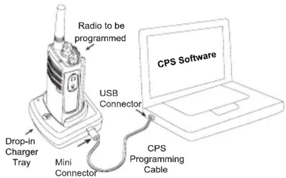
The easiest way to program or change features in your radio is by using the Computer Programming Software (CPS) and the CPS Programming Cable(*). CPS Software is available for free as web based downloadable software at:
www.motorolasolutions.com/RDX
To program, connect the RDX Series ™ radio via the Drop-in Charger Tray and CPS Programming Cable as shown in the picture above.
CPS allows the user to program frequencies, PL/DPL codes, as well as other features such as: Time-out Timer, Power Select, Battery Type Select, Scan List, Call Tones, Scramble, Reverse Burst, etc. CPS is a very useful tool as it can also lock the Front-Panel Radio Programming or restrict any specific radio feature to be changed (to avoid accidentally erasing the preset radio values). It also provides security by giving the option to set up a password for profile radio's management. Please refer to Features Summary Chart Section at the end of the user guide for more details.
Note: (*) CPS Programming Cable (P/N RKN4155) is an accessory sold separately. Please contact your Motorola point of purchase for more information.
Time-Out Timer
When pressing the PTT button, transmissions can be terminated by setting up a 'time-out' timer.
Power Select
Power Select allows you to select between high and low transmission power per frequency in each channel. The power levels for RDX Series™ 2W toggle between 1W and 2W or 2W and 4W/5W depends on the model.
Note: Some frequencies may have FCC transmit power restrictions that do not allow them to be set at a higher power level. For details see the Frequencies and Code Chart Section.
Battery Type Setting
The RDX Series ™ radio can be powered by either Alkaline or Lithium-Ion batteries.
Call Tones
Call Tones feature allows you to transmit to other radios in your group by alerting them that you are about to talk or alerting them without speaking.
Scramble

The Scramble feature makes transmissions sound garbled to anyone listening without the same code. Scramble default value is OFF.
Reverse Burst
Reverse Burst eliminates unwanted noise (squelch tail) during loss of carrier detection. You can select values of either 180/240.
Notes:
- The features described in previous pages are just some of the features CPS has. CPS offers more capabilities. For more information refer to the HELP file in the CPS.
- Some of the features available with the CPS software may vary depending on the radio model.
English
CLONING RADIOS
You can clone RDX Series ™ radio profiles from one Source radio to a Target radio by using any one of these 3 methods:
- a Multi Unit Charger (optional accessory),
- Two Single Unit Chargers (SUC) and a Radio-to-Radio cloning cable (optional accessory),
• the CPS (free software download)
Cloning with a Multi Unit Charger (MUC)

To clone radios using the MUC, there must be at least two radios:
- a Source radio (radio which profiles will be cloned
or copied from) and
- a Target radio (the radio which profile will be cloned from the source radio.)
The Source radio has to be in Pocket 1, 3 or 5 while the Target radio has to be in Pocket 2, 4 or 6, matching in the MUCs pockets by pairs as follows:
• 1 and 2 or,
• 3 and 4 or,
- 5 and 6 (*).
When cloning, the MUC does not need to be plugged into a power source, but ALL radios require charged batteries.
- Turn ON the Target radio and place it into one of the MUC Target Pockets
- Power the Source radio following the sequence below:
- Long press the PTT button and SB2 simultaneously while turning the radio ON.
- Wait for 3 seconds before releasing the buttons until a distinctive audible tone is heard.
- Place the Source radio in the source pocket that pairs with the target pocket you chose in step 1. Press and release SB1.
- After cloning is completed, the Source radio will sound either a 'pass' tone (cloning was successful) or a 'fail' tone (cloning process has failed). The 'pass' tone sounds like a good key 'chirp' whereas the 'fail' tone sounds similar to a 'bonk' tone. If the Source radio is a display model, it will either show 'Pass' or 'Fail' on the display (a tone will be heard within 5 seconds).
- Once you have completed the cloning process, turn the radios OFF and ON to exit the 'cloning' mode.
- If cloning fails please refer to "What To Do if Cloning Fails" on page 54.
Further details on how to clone radios are explained in the Instructions Sheet provided with the MUC.
When ordering the MUC, please refer to P/N RLN6309.
Notes:
- Paired Target radios and Source radios must be of the same band type in order for the cloning to run successfully.
- (*) MUC pockets numbers should be read from left to right with the Motorola logo facing front.
Cloning Radio using the Radio to Radio (R2R) Cloning Cable (Optional Accessory)

Operating Instructions
- Before beginning the cloning process, make sure you have:
• A fully charged battery on each one of the radios.
• Two Single Unit Chargers (SUC).
• Turned OFF the radios and,
- Both radios are of the same radio model.
- Unplug any cables (power supply or USB cables) from the SUCs.
- Plug one side of the cloning cable mini connector to one SUC. Plug the other end to the second SUC.
Note: During the cloning process no power is being applied to the SUC. The batteries will not be charged. A data communication is being established between the two radios.
- Turn ON the Target radio and place it into one of the SUCs.
- On the Source radio, power the radio following the sequence below:
- Long press the PTT button and SB2 simultaneously while turning the radio ON.
- Wait for 3 seconds before releasing the buttons until a distinctive audible tone is heard.
-
Place the Source radio in its SUC, press and release SB1.
-
After cloning is completed, the Source radio will sound either a 'pass' tone (cloning was successful) or a 'fail' tone (cloning process has failed). The 'pass' tone sounds like a good key 'chirp' whereas the 'fail' tone sounds similar to a 'bonk' tone. If the Source radio is a display model, it will either show 'Pass' or 'Fail' on the display (a tone will be heard within 5 seconds).
-
Once you have completed the cloning process, turn the radios OFF and ON to exit 'clone' mode.
What To Do if Cloning Fails
The radio will emit an audible ‘bonk’ indicating that the cloning process has failed. In the event that cloning fails, try performing each of the following before trying to start the cloning process again:
- Ensure that the batteries on both radios are fully charged.
-
Check the cloning cable connection on both SUCs.
-
Ensure that the battery is engaged properly on to the radio.
- Ensure that there is no debris in the charging tray or on the radio contacts.
- Ensure that the Source radio is in cloning mode.
- Ensure that the Target radio is turned ON.
- Ensure that radios are both from the same type (same frequency band, same front panel (display/non display), same region and same transmission power).
Note: This cloning cable is designed to operate only with compatible Motorola RLN6175 (Standard) and RLN6304 (Rapid) Single Unit Chargers.
When ordering Cloning Cable please refer to P/N RLN6303. For details about accessories refer to Accessories section.
Cloning using the CPS (Computer Programming Software)
When cloning using this method, you will need to have the CPS software, a Drop-in Tray Charger and the CPS Programming Cable.
To order the CPS Programming Cable, please refer to P/N RKN4155.
Information on how to clone using the CPS is available either in:
- the CPS Help File --> Content and Index --> Cloning Radios, or
- in the CPS Programming Cable Accessory Leaflet.
TROUBLESHOOTING
| Symptom Try This... | |
| No Power | Recharge or replace the Li-Ion battery.Reposition or replace AA batteries.Extreme operating temperatures may affect battery life.Refer to See “About the Li-Ion Battery” on page 14. |
| Hearing other noises or conversation on a channel | Confirm Interference Eliminator Code is set.Frequency or Interference Eliminator Code may be in use.Change settings: either change frequencies or codes on all radios.Make sure radio is at the right frequency and code when transmitting.Refer to “Talking and Monitoring” on page 29 |
| Message Scrambled | Scramble Code might be ON, and/or setting does not match the other radios' settings. |
| Audio quality not good enough | Radio settings might not be matching up correctly. Double check frequencies,codes and bandwidths to make sure they are identical in all radios |
English
| Symptom Try This... | |
| Limited talk range | Steel and/or concrete structures, heavy foliage, buildings or vehicles decrease range. Check for clear line of sight to improve transmission.Wearing radio close to body such as in a pocket or on a belt decreases range.Change location of radio. To increase range and coverage, you can either reduce obstructions, increase power, or use UHF radio instead of VHF radio.UHF radios provide greater coverage in industrial and commercial buildings.VHF is designed for outdoor or smaller or wood structures. Increasing power provides greater signal range and increased penetration through obstructions.Refer to See “Talking and Monitoring” on page 29. |
| Message not transmitted or received | Make sure the PTT button is completely pressed when transmitting.Confirm that the radios have the same Channel, Frequency, Interference Eliminator Code and Scramble Code settings. Refer to “Talking and Monitoring” section on page 29 for further information.Recharge, replace and/or reposition batteries. Refer to “About your Li-Ion Battery” section on page 14.Obstructions and operating indoors, or in vehicles, may interfere. Change location. Refer to “Talking and Monitoring” Section on page 29.Verify that the radio is not in Scan. Refer to “Scan” on page 46 and “Nuisance Channel Delete” on page 47. |
| Heavy static or interference | Radios are too close; they must be at least five feet apart.Radios are too far apart or obstacles are interfering with transmission.Refer to “Talking and Monitoring” on page 29. |
| Low batteries | Recharge or replace Li-lon battery. Replace AA batteries.Extreme operating temperatures affect battery life.Refer to “About the Li-lon Battery” on page 14. |
| Drop-in Charger LED light does not blink | Check that the radio/battery is properly inserted and check the battery/charger contacts to ensure that they are clean and charging pin is inserted correctly.Refer to “Charging the Battery” section on page 22, “Drop-in Tray Charger LED Indicators” section on page 25 and “Installing the Lithium-lon Battery” section on page 16. |
| Low battery indicator is blinking although new batteries are inserted | Verify that the radio is set to the correct battery type.Refer to “Installing the Li-lon Battery” section on page 16, “Installing Alkaline Batteries” section on page 17 and “About your Li-lon Battery” section on page 14. |
| Cannot activate VOX | VOX feature might be set to OFF.Use the CPS to ensure that the VOX Sensitivity level is not set to '0'.Accessory not working or not compatible.Refer to “Hands-Free Use/VOX” section on page 33. |
| Battery does not charge although it has been placed in the drop-in charger for a while | Check drop-in tray charger is properly connected and correspond to a compatible power supply.Ensure that you have the drop-in tray charger adjustable piece placed on the right position.Refer to “Charging with the Drop-In Tray Single Unit Charger” section on page 22 and “Charging a Standalone Battery” section on page 23.Check the charger's LEDs indicators to see if the battery has a problem. Refer to “Drop-in Tray Charger LED Indicators” section on page 25. |
Note: Whenever a feature in the radio seems to not correspond to the default or preprogrammed values, check to see if the radio has been programmed using the CPS with a customized profile.
USE AND CARE

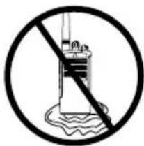
Use a soft damp cloth to clean the exterior
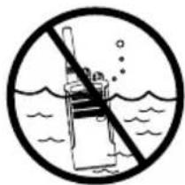
Do not immerse in water

Do not use alcohol or cleaning solutions
If the radio is submerged in water...

Turn radio OFF and remove batteries

Dry with soft cloth Do not use radio until
completely dry
English
FREQUENCY AND CODE CHARTS
RDX VHF FREQUENCIES CHART
The charts in this section provide Frequency and Code information. These charts are useful when using Motorola RDX Series™ two-way radios with other business radios. Most of the frequency's positions are the same as Spirit M, GT, S, and XTN Series Frequencies.
RDX VHF Frequencies
| Frequency # | Frequency (MHz) | Bandwidth F | Frequency # | Frequency (MHz) | Bandwidth |
| 1 | 151.6250 | 12.5 kHz | 12 | 151.6850 | 12.5 kHz |
| 2 | 151.9550 | 12.5 kHz | 13 | 151.7150 | 12.5 kHz |
| 3 | 152.8850 | 12.5 kHz | 14 | 151.7450 | 12.5 kHz |
| 4 | 152.9150 | 12.5 kHz | 15 | 151.7750 | 12.5 kHz |
| 5 | 151.7000 | 12.5 kHz | 16 | 151.8650 | 12.5 kHz |
| 6 | 151.7600 | 12.5 kHz | 17 | 151.8950 | 12.5 kHz |
| *7 | 152.9450 | 12.5 kHz | 18 | 151.9250 | 12.5 kHz |
| *8 | 151.8350 | 12.5 kHz | 19 | 152.9000 | 12.5 kHz |
| *9 | 151.8050 | 12.5 kHz | 20 | 154.4900 | 12.5 kHz |
| 10 151.51 | 25 12.5 kHz 21 | 154.5150 12.5 kHz | |||
| 11 | 151.6550 | 12.5 kHz | 22 | 154.5275 | 12.5 kHz |
RDX VHF Frequencies (cont.)
| Frequency # | Frequency (MHz) | Bandwidth F |
| 23 | 154.500 | 12.5 kHz |
| 24 153.00 | 50 12.5 kHz | |
| 25 154.54 | 75 12.5 kHz |
| ency # | Frequency (MHz) | Bandwidth |
| 26 | 158.4000 | 12.5 kHz |
| 27 158.40 | 75 12.5 kHz |
Notes:
(*) Due to FCC regulations these frequencies (six in total) are different from the previous Motorola Legacy Series radios. This means that if you select the RDX radio in one of these frequencies the radio will not inter-operate with an XTN radio. In order for a RDX radio to inter-operate with an XTN radio, make sure you choose any of the frequencies (21 in total) that are common for both radios.
PLEASE NOTICE THAT THE FACTORY DEFAULT CONFIGURATION OF THE RDX RADIOS HAVE BEEN MODIFIED TO BE IN COMPLIANCE WITH THE 2013 FCC NARROWBAND MANDATE. THIS MANDATE REQUIRES RADIO OPERATORS TO SWITCH THE CONFIGURATION OF THEIR EQUIPMENT TO 12.5 KHZ CHANNEL BANDWIDTH BY JANUARY 1ST, 2013. THE RDX RADIO CHANNEL BANDWIDTH DEFAULT HAS BEEN SET AT 12.5 KHZ.
IF THIS NEW RADIO IS AN ADDITION OR REPLACEMENT TO AN EXISTING GROUP OF RADIOS WITH 25 KHz SETTING (LEGACY FACTORY CONFIGURATION), ACTION MAY BE REQUIRED ON YOUR PART IN ORDER TO OPTIMIZE OPERATION OF YOUR FLEET AND BE IN COMPLIANCE WITH FCC RULES.
TO CHANGE THE CHANNEL BANDWITH OF YOUR OLDER RDX RADIO FROM 25 KHZ TO 12.5 KHZ YOU MAY USE THE CUSTOMER PROGRAMMING SOFTWARE AVAILABLE FOR FREE DOWNLOAD AT HYPERLINK "http://www.motorola.com/RDX" WWW.MOTOROLASOLUTIONS.COM/RDX (PROGRAMMING CABLE REQUIRED) OR YOU CAN FOLLOW DIRECTIONS IN THE USER GUIDE UNDER 'PROGRAMMING FEATURES'.
IF YOU HAVE QUESTIONS OR NEED FURTHER ASSISTANCE, PLEASE CONTACT OUR CUSTOMER CARE TEAM AT +800-448-6686.
FOR ADDITIONAL DETAILS ON THE NARROWBAND MANDATE PLEASE VISIT WWW.MOTOROLASOLUTIONS.COM/NARROWBANDING
English
RDV2020 - VHF DEFAULT FREQUENCIES CHART
BRUS RDX VHF 2CH Radios Default Frequencies - RDV2020
| Channel Frequency # | Frequency (MHz) | Code # Code Bandwidth | |||
| 1 20 154 | 4900 1 67.0 Hz 12 | .5 kHz | |||
| 2 21 154 | 5150 1 67.0 Hz 12 | .5 kHz | |||
RDV5100 - VHF DEFAULT FREQUENCIES CHART
RDX VHF 10CH Radios Default Frequencies - RDV5100
| Channel Frequency # | Frequency (MHz) | Code # Code Bandwidth | |||
| 1 | 1 151.6 | 250 1 67.0 Hz 12.5 kHz | |||
| 2 | 1 151.6 | 250 4 77.0 Hz 12.5 kHz | |||
| 3 | 1 151.6 | 250 8 88.5 Hz 12.5 kHz | |||
| 4 | 1 151.6 | 250 29 179.9 Hz 12.5 kHz | |||
| 5 | 1 151.6 | 250 0 - 12.5 kHz | |||
| 6 | 2 151.9 | 550 1 67.0 Hz 12.5 kHz | |||
| 7 | 2 151.9 | 550 6 82.5 Hz 12.5 kHz | |||
| 8 | 2 | 151.9550 | 10 | 94.8 Hz | |
| 9 | 2 151.9 | 550 29 179.9 Hz 12.5 kHz | |||
| 10 | 2 | 151.9550 | 0 | - | |
RDX UHF FREQUENCIES CHART
RDX UHF Frequencies
| Frequency # | Frequency (MHz) | Bandwidth F |
| 1 464.500 | 12.5 kHz 14 | 461.1625 12.5 kHz |
| 2 464.550 | 12.5 kHz 15 | 461.1875 12.5 kHz |
| *3 467.762 | 25 12.5 kHz | |
| *4 | 467.8125 | 12.5 kHz |
| *5 467.850 | 0 12.5 kHz | |
| *6 | 467.8750 | 12.5 kHz |
| *7 467.900 | 0 12.5 kHz | |
| *8 | 467.9250 | 12.5 kHz |
| 9 461.037 | 5 12.5 kHz | |
| 10 | 461.0625 | 12.5 kHz |
| 11 461.087 | 5 12.5 kHz | |
| 12 | 461.1125 | 12.5 kHz |
| 13 461.137 | 75 12.5 kHz |
| ency # | Frequency (MHz) | Bandwidth |
| 16 461.2125 | 12.5 kHz | |
| 17 | 461.2375 | 12.5 kHz |
| 18 461.2625 | 12.5 kHz | |
| 19 | 461.2875 | 12.5 kHz |
| 20 461.3125 | 12.5 kHz | |
| 21 | 461.3375 | 12.5 kHz |
| 22 461.3625 | 12.5 kHz | |
| *23 | 462.7625 | 12.5 kHz |
| *24 462.7875 | 12.5 kHz | |
| *25 | 462.8125 | 12.5 kHz |
| *26 462.8375 | 12.5 kHz | |
| Frequency # | Frequency (MHz) | Bandwidth F |
| *27 | 462.8625 | 12.5 kHz |
| *28 | 462.8875 | 12.5 kHz |
| *29 | 462.9125 | 12.5 kHz |
| 30 464.4875 | 12.5 kHz 41 | 466.2125 12.5 kHz |
| 31 464.5125 | 12.5 kHz 42 | 466.2375 12.5 kHz |
| 32 464.5375 | 12.5 kHz 43 | 466.2625 12.5 kHz |
| 33 464.5625 | 12.5 kHz 44 | 466.2875 12.5 kHz |
| 34 466.0375 | 12.5 kHz 45 | 466.3125 12.5 kHz |
| 35 466.0625 | 12.5 kHz 46 | 466.3375 12.5 kHz |
| 36 466.0875 | 12.5 kHz 47 | 466.3625 12.5 kHz |
| 37 | 466.1125 | 12.5 kHz |
| ency # | Frequency (MHz) | Bandwidth |
| 38 | 466.1375 | 12.5 kHz |
| 39 | 466.1625 | 12.5 kHz |
| 40 | 466.1875 | 12.5 kHz |
| *48 | 467.7875 | 12.5 kHz |
| Frequency # | Frequency (MHz) | Bandwidth R |
| *49 | 467.8375 | 12.5 kHz |
| *50 | 467.8625 | 12.5 kHz |
| *51 | 467.8875 | 12.5 kHz |
| *52 | 467.9125 | 12.5 kHz |
| 53 469.4875 | 12.5 kHz 65 | 451.1875 12.5 kHz |
| 54 469.5125 | 12.5 kHz 66 | 451.2375 12.5 kHz |
| 55 469.5375 | 12.5 kHz 67 | 451.2875 12.5 kHz |
| 56 469.5625 | 12.5 kHz 68 | 451.3375 12.5 kHz |
| 57 462.1875 | 12.5 kHz 69 | 451.4375 12.5 kHz |
| 58 462.4625 | 12.5 kHz 70 | 451.5375 12.5 kHz |
| 59 462.4875 | 12.5 kHz 71 | 451.6375 12.5 kHz |
| 60 462.5125 | 12.5 kHz 72 | 452.3125 12.5 kHz |
| ency # | Frequency (MHz) | Bandwidth |
| 61 | 467.1875 | 12.5 kHz |
| 62 | 467.4625 | 12.5 kHz |
| 63 | 467.4875 | 12.5 kHz |
| 64 | 467.5125 | 12.5 kHz |
| Frequency # | Frequency (MHz) | Bandwidth F |
| 73 452.5375 | 12.5 kHz 82 | 456.4375 12.5 kHz |
| 74 452.4125 | 12.5 kHz 83 | 456.5375 12.5 kHz |
| 75 452.5125 | 12.5 kHz 84 | 456.6375 12.5 kHz |
| 76 452.7625 | 12.5 kHz 85 | 457.3125 12.5 kHz |
| 77 452.8625 | 12.5 kHz 86 | 457.4125 12.5 kHz |
| 78 456.1875 | 12.5 kHz 87 | 457.5125 12.5 kHz |
| 79 456.2375 | 12.5 kHz 88 | 457.7625 12.5 kHz |
| 80 456.2875 | 12.5 kHz 89 | 457.8625 12.5 kHz |
| 81 456.3375 | 12.5 kHz |
| ency # | Frequency (MHz) | Bandwidth |
Notes:
• (*) Frequency limited to 2W maximum power output
- When referring to XTN radios, note that frequencies from # 57 to # 89 are 33 new additional frequencies
English
RDU2020 - UHF DEFAULT FREQUENCIES CHART
RDX UHF 2CH Radios Default Frequencies - RDU2020
| Channel Frequency # | Frequency (MHz) | Code # Code Bandwidth | ||
| 1 2 464.5500 1 67.0 Hz 12.5 kHz | ||||
| 2 8 467.9250 1 67.0 Hz 12.5 kHz | ||||
RDU4100 - UHF DEFAULT FREQUENCIES CHART
RDX UHF 10 CH Radios Default Frequencies - RDU4100
| Channel Frequency # | Frequency (MHz) | Code # Code Bandwidth | |||
| 1 | 1 464.5000 | 1 67.0 Hz 12.5 kHz | |||
| 2 | 1 464.5000 | 4 77.0 Hz 12.5 kHz | |||
| 3 | 1 464.5000 | 8 88.5 Hz 12.5 kHz | |||
| 4 | 1 | 464.5000 | 29 | 179.9 Hz | 12.5 kHz |
| 5 | 1 464.5000 | 0 - 12.5 kHz | |||
| 6 | 2 464.5500 | 1 67.0 Hz 12.5 kHz | |||
| 7 | 2 464.5500 | 6 82.5 Hz 12.5 kHz | |||
| 8 | 2 | 464.5500 | 10 | 94.8 Hz | 12.5 kHz |
| 9 | 2 464.5500 | 29 179.9 Hz 12.5 kHz | |||
| 10 | 2 | 464.5500 | 0 | - | 12.5 kHz |
CTCSS AND PL/DPL CODES
CTCSS Codes
| CTCSS Hz CTCSS Hz | SS Hz | |||||||
| 1 67.0 | 14 | 107.2 | 27 167.9 | |||||
| 2 71.9 | 15 | 110.9 | 28 173.8 | |||||
| 3 74.4 | 16 | 114.8 | 29 179.9 | |||||
| 4 77.0 | 17 | 118.8 | 30 186.2 | |||||
| 5 79.7 | 18 | 123 | 31 192.8 | |||||
| 6 82.5 | 19 | 127.3 | 32 203.5 | |||||
| 7 85.4 | 20 | 131.8 | 33 210.7 | |||||
| 8 88.5 | 21 | 136.5 | 34 218.1 | |||||
| 9 91.5 | 22 | 141.3 | 35 225.7 | |||||
| 10 94.8 | 23 | 146.2 | 36 233.6 | |||||
| 11 97.4 | 24 | 151.4 | 37 241.8 | |||||
| 12 100.0 | 25 | 156.7 | 38 250.3 | |||||
| 13 103.5 | 26 | 162.2 | 122 (*) | 69.3 | ||||
Note: (*) New CTCSS code.
PL/DPL Codes
| DPL Code DPL Code | ode | ||||||
| 39 23 | 55 116 71 243 | ||||||
| 40 25 | 56 125 72 244 | ||||||
| 41 26 | 57 131 73 245 | ||||||
| 42 31 | 58 132 74 251 | ||||||
| 43 32 | 59 134 75 261 | ||||||
| 44 43 | 60 143 76 263 | ||||||
| 45 47 | 61 152 77 265 | ||||||
| 46 51 | 62 155 78 271 | ||||||
| 47 54 | 63 156 79 306 | ||||||
| 48 65 | 64 162 80 311 | ||||||
| 49 71 | 65 165 81 315 | ||||||
| 50 72 | 66 172 82 331 | ||||||
| 51 73 | 67 174 83 343 | ||||||
| 52 74 | 68 205 84 346 | ||||||
| 53 114 | 69 223 85 351 | ||||||
| 54 115 | 70 226 | 86 364 | |||||
English
PL/DPL Codes (Continued)
| DPL | Code | DPL | Code | DPL | Code | ||
| 87 365 | 104 565 121 754 | ||||||
| 88 371 | 105 606 123 645 | ||||||
| 89 411 | 106 6 | 12 124 Customized PL | |||||
| 90 412 | 107 624 125 Customized PL | ||||||
| 91 413 | 108 627 126 Customized PL | ||||||
| 92 423 | 109 631 127 Customized PL | ||||||
| 93 431 | 110 632 128 Customized PL | ||||||
| 94 432 | 111 654 129 Customized PL | ||||||
| 95 445 | 112 662 130 Inverted DPL 39 | ||||||
| 96 464 | 113 664 131 Inverted DPL 40 | ||||||
| 97 465 | 114 703 132 Inverted DPL 41 | ||||||
| 98 466 | 115 712 133 Inverted DPL 42 | ||||||
| 99 503 | 116 723 134 Inverted DPL 43 | ||||||
| 100 506 | 117 731 135 Inverted DPL 44 | ||||||
| 101 516 | 118 732 136 Inverted DPL 45 | ||||||
| 102 532 | 119 734 137 Inverted DPL 46 | ||||||
| 103 546 | 120 743 138 Inverted DPL 47 |
PL/DPL Codes (Continued)
| DPL Code DPL Code | ode | |||||
| 139 | Inverted DPL 48 | 156 | Inverted DPL 65 | 173 | Inverted DPL 82 | |
| 140 | Inverted DPL 49 | 157 | Inverted DPL 66 | 174 | Inverted DPL 83 | |
| 141 | Inverted DPL 50 | 158 | Inverted DPL 67 | 175 | Inverted DPL 84 | |
| 142 | Inverted DPL 51 | 159 | Inverted DPL 68 | 176 | Inverted DPL 85 | |
| 143 | Inverted DPL 52 | 160 | Inverted DPL 69 | 177 | Inverted DPL 86 | |
| 144 | Inverted DPL 53 | 161 | Inverted DPL 70 | 178 | Inverted DPL 87 | |
| 145 | Inverted DPL 54 | 162 | Inverted DPL 71 | 179 | Inverted DPL 88 | |
| 146 | Inverted DPL 55 | 163 | Inverted DPL 72 | 180 | Inverted DPL 89 | |
| 147 | Inverted DPL 56 | 164 | Inverted DPL 73 | 181 | Inverted DPL 90 | |
| 148 | Inverted DPL 57 | 165 | Inverted DPL 74 | 182 | Inverted DPL 91 | |
| 149 | Inverted DPL 58 | 166 | Inverted DPL 75 | 183 | Inverted DPL 92 | |
| 150 | Inverted DPL 59 | 167 | Inverted DPL 76 | 184 | Inverted DPL 93 | |
| 151 | Inverted DPL 60 | 168 | Inverted DPL 77 | 185 | Inverted DPL 94 | |
| 152 | Inverted DPL 61 | 169 | Inverted DPL 78 | 186 | Inverted DPL 95 | |
| 153 | Inverted DPL 62 | 170 | Inverted DPL 79 | 187 | Inverted DPL 96 | |
| 154 | Inverted DPL 63 | 171 | Inverted DPL 80 | 188 | Inverted DPL 97 | |
| 155 | Inverted DPL 64 | 172 | Inverted DPL 81 | 189 | Inverted DPL 98 | |
English
PL/DPL Codes (Continued)
| DPL | Code | DPL | Code | DPL | Code | ||
| 190 | Inverted DPL 99 200 | Inverted | DPL 1 | 09 210 Inverted DPL 119 | |||
| 191 | Inverted DPL 100 | 201 | Inverted DPL 110 | 211 | Inverted DPL 120 | ||
| 192 | Inverted DPL 101 202 | Inverted | DPL | 111 212 Inverted DPL 121 | |||
| 193 | Inverted DPL 102 | 203 | Inverted DPL 112 | 213 | Inverted DPL 123 | ||
| 194 | Inverted DPL 103 204 | Inverted | DPL | 113 214 Customized DPL | |||
| 195 | Inverted DPL 104 | 205 | Inverted DPL 114 | 215 | Customized DPL | ||
| 196 | Inverted DPL 105 206 | Inverted | DPL | 115 216 Customized DPL | |||
| 197 | Inverted DPL 106 | 207 | Inverted DPL 116 | 217 | Customized DPL | ||
| 198 | Inverted DPL 107 208 | Inverted | DPL | 117 218 Customized DPL | |||
| 199 | Inverted DPL 108 | 209 | Inverted DPL 118 | 219 | Customized DPL |
PROGRAMMING CUSTOMIZED FREQUENCIES ON 4W/5W RDX MODELS
4W/5W Models can be programmed to have customized frequencies (different from the ones shown in the VHF and UHF charts in previous pages). VHF range is 146 -174 MHz and UHF 438 - 470 MHz.
4W/5W models can also be programmed to work with repeaters.
Please contact your Motorola point of purchase for details.
MOTOROLA LIMITED WARRANTY FOR THE UNITED STATES AND CANADA
What Does this Warranty Cover?
Subject to the exclusions contained below, Motorola, Inc. warrants its telephones, pagers, and consumer and business two-way radios (excluding commercial, government or industrial radios) that operate via Family Radio Service or General Mobile Radio Service, Motorola-branded or certified accessories sold for use with these Products (“Accessories”) and Motorola software contained on CD-ROMs or other tangible media and sold for use with these Products (“Software”) to be free from defects in materials and workmanship under normal consumer usage for the period(s) outlined below.
This limited warranty is a consumer's exclusive remedy, and applies as follows to new Motorola Products, Accessories and Software purchased by consumers in the United States, which are accompanied by this written warranty.
Products and Accessories
| Products Covered Length of Coverage | |
| Products and Accessories as defined above, unless otherwise provided for below. | One (1) year from the date of purchase by the first consumer purchaser of the product unless otherwise provided for below. |
| Decorative Accessories and Cases. Decorative covers, bezels, PhoneWrapTM covers and cases. | Limited lifetime warranty for the lifetime of ownership by the first consumer purchaser of the product. |
| Business Two-way Radio Accessories | One (1) year from the date of purchase by the first consumer purchaser of the product. |
| Products and Accessories that are Repaired or Replaced. | The balance of the original warranty or for ninety (90) days from the date returned to the consumer, whichever is longer. |
English
Exclusions
Normal Wear and Tear. Periodic maintenance, repair and replacement of parts due to normal wear and tear are excluded from coverage.
Batteries. Only batteries whose fully charged capacity falls below 80% of their rated capacity and batteries that leak are covered by this limited warranty.
Abuse & Misuse. Defects or damage that result from: (a) improper operation, storage, misuse or abuse, accident or neglect, such as physical damage (cracks, scratches, etc.) to the surface of the product resulting from misuse; (b) contact with liquid, water, rain, extreme humidity or heavy perspiration, sand, dirt or the like, extreme heat, or food; (c) use of the Products or Accessories for commercial purposes or subjecting the Product or Accessory to abnormal usage or conditions; or (d) other acts which are not the fault of Motorola, are excluded from coverage.
Use of Non-Motorola Products and
Accessories. Defects or damage that result from the use of Non-Motorola branded or certified Products, Accessories, Software or other peripheral equipment are excluded from coverage.
Unauthorized Service or Modification. Defects or damages resulting from service, testing, adjustment, installation, maintenance, alteration, or modification in any way by someone other than Motorola, or its authorized service centers, are excluded from coverage.
Altered Products. Products or Accessories with (a) serial numbers or date tags that have been removed, altered or obliterated; (b) broken seals or that show evidence of tampering; (c) mismatched board serial numbers; or (d) nonconforming or non-Motorola housings, or parts, are excluded from coverage.
Communication Services. Defects, damages, or the failure of Products, Accessories or Software due to any communication service or signal you may subscribe to or use with the Products Accessories or Software is excluded from coverage.
Software
| Products Covered Length of Coverage | |
| Software. Applies only to physical defects in the media that embodies the copy of the software (e.g. CD-ROM, or floppy disk). | Ninety (90) days from the date of purchase. |
Exclusions
Software Embodied in Physical Media. No warranty is made that the software will meet your requirements or will work in combination with any hardware or software applications provided by third parties, that the operation of the software products will be uninterrupted or error free, or that all defects in the software products will be corrected.
Software NOT Embodied in Physical Media. Software that is not embodied in physical media (e.g. software that is downloaded from the internet), is provided “as is” and without warranty.
WHO IS COVERED?
This warranty extends only to the first consumer purchaser, and is not transferable.
HOW TO OBTAIN WARRANTY SERVICE OR OTHER INFORMATION?
Contact your Motorola point of purchase.
SOFTWARE COPYRIGHT NOTICE
The Motorola products described in this manual may include copyrighted Motorola and third party software stored in semiconductor memories or other media. Laws in the United States and other countries preserve for Motorola and third party software providers certain exclusive rights for copyrighted software, such as the exclusive rights to distribute or reproduce the copyrighted software. Accordingly, any copyrighted software contained in the Motorola products may not be modified, reverse-engineered, distributed, or reproduced in any manner to the extent allowed by law.
Furthermore, the purchase of the Motorola products shall not be deemed to grant either directly or by implication, estoppel, or otherwise, any license under the copyrights, patents, or patent applications of Motorola or any third party software provider, except for the normal, non-exclusive, royalty-free license to use that arises by operation of law in the sale of a product.
PATENT NOTICE
This product is covered by one or more of the following United States patents. 5896277 5894292 5864752 5699006 5742484 D408396 D399821 D387758 D389158 5894592 5893027 5789098 5734975 5861850 D395882 D383745 D389827 D389139 5929825 5926514 5953640 6071640 D413022 D416252 D416893 D433001
EXPORT LAW ASSURANCES
This product is controlled under the export regulations of the United States of America. The Governments of the United States of America may restrict the exportation or re-exportation of this product to certain destinations. For further information contact the U.S. Department of Commerce.
ACCESSORIES
ANTENNAS
| Part No. Description | |
| RAN4033 | UHF Stubby Antenna 450-470 MHz |
| RAN4041 | VHF Helical Antenna 146-174 MHz |
| RAN4031 | UHF Whip Antenna 438 - 470 MHz |
AUDIO ACCESSORIES
| Part No. Description | |
| 53815 Headset w/Boom Mic BR | |
| HMN9026 Remote Speaker Mic BR | |
| HKLN4477 Surveillance Earpiece BR |
Part No. Description
| 53865 Headset w/Swivel Boom Mic |
| 53866 Earbud w/Clip PTT Mic BR |
| 56517 Earpiece w/Inline Mic |
| RLN6423 Swivel Earpiece BR |
BATTERY
| Part No. Description | |
| RLN6306 Alkaline Battery Frame | |
| RLN6351 Standard Li-Ion Battery | |
| RLN6308 | Ultra High Capacity Li-Ion Battery |
CARRY ACCESSORIES
| Part No. Description | |
| RLN6302 Hard | Leather Carry Case |
| RLN6307 Spring | Action Belt Clip |
POWER SUPPLIES AC PIN ADAPTORS
| Part No. Description | |
| RLN6349 North | America AC Pin Adaptor |
SOFTWARE APPLICATIONS
| Part No. Description | |
| RVN5147 | Computer Programming Software (CPS) |
CABLES
| Part No. Description | |
| RLN6303 Radio | to Radio Cloning Cable |
| RKN4155 CPS | Programming Cable |
CHARGERS
| Part No. Description | |
| RLN6304 | Rapid ACCY Charging Kit - Americas (*) |
| RLN6309 | Multi Unit Charger (MUC) Kit - North America |
| RLN6175 Standard Drop-in Tray Charger | |
POWER SUPPLIES
| Part No. Description | |
| RPN4054 | Standard US Fixed Power Supply |
| RPN4058 | Standard Exchg AC pin Pwr Supply |
| RLN6170 Rapid | Exchg AC pin Pwr Supply |
Attention: Certain accessories may be or may not be available at the time of purchase. For latest information on accessories, contact your Motorola point of purchase or visit:
www.motorolasolutions.com/RDX
(*) Americas Rapid Charging Kit includes Power Supply, Drop-in Tray Charger, and AC Pin adaptors.
RDX Series™ Features Summary

MOTOROLA
| Features | Programmable Via RADIO PANEL | Programmable via CPS | Default Value Programming Tips | |||
| Display | Non-Display | Display | Non-Display | |||
| Backlight | No | N/A | Yes | N/A | 5 Seconds | Choose the backlight's time out by using the CPS. |
| Bandwidth Select | Yes No Yes Yes | Frequency Dependable | Front panel programming available only on display models by entering Programming Mode (1). Bandwidth is programmable according to FCC frequency regulations. Refer to the Frequencies and Code Charts Section for details. | |||
| Battery Save (2) | Yes Yes Yes ON | To enable/disable Battery Save, press SB1 and SB2 simultaneously while turning ON the radio. | ||||
| Battery Type | Yes | No | Yes | Yes | Li-Ion | Front panel radio programming is available in display models by pressing the MENU button and scrolling down/up with and buttons to set value. Long press PTT to save and exit. |
| Buttons Reset | No | No | Yes | Yes | ON | Available only via CPS. Allows to reset the radio buttons to factory default values. Refer to Radio Buttons Summary Table. |
| Call Tones (4) Yes No Yes Yes | OFF/ BUTTON A | Front panel radio programming available only for Display Models by going into Programming Mode(1). Values available are 0 (OFF), 1, 2 and 3. To enable/disable Call Tones press Button A (default button). | ||||
| Channel Allasing | Yes N/A | Yes N/A OFF | Only Display Models. To enter or exit Channel Aliasing mode press PTT and buttons simultaneously while turning radio ON for 3 sec. After editing, to exit and save, long press PTT.Note:To edit, refer to Programming Features/ Editing Channels. | |||
| Channels Yes Yes Yes Model Dependant | You can select channels using the Channel Selector Knob (non-display models) or the MENU button (display models). You can also add or delete channels by using the CPS.Note:Enabling/disabling channels via CPS will automatically affect the Max Channels you are able to program via front panel. | |||||
| Cloning Mode | Yes Yes Yes | OFF | Enables radio to enter cloning mode in order to clone its profile settings into other radios (using Radio to Radio Cloning Cable or Multi-Unit Charger). Press PTT, SB2 while turning radio ON. Note: You can clone radios using the CPS. | |||
| CPS Manager Lock | No No | Yes Yes N/A | This feature is referred in the CPS software as “Codeplug Password”. It prevents unauthorized access to the CPS to the radio's programmed configuration. Make sure you set up a 4 digits password that is easy to remember. | |||
| End of Tx Tone (or Roger Beep) (2) | Yes Yes | Yes Yes OFF | To enable/disable press SB1 while powering up the radio | |||
| Frequencies Yes | Yes Yes Yes | Channel and Model Dependant | There are 27 VHF frequencies and 89 UHF frequencies available. Use Programming Mode (1) for front panel radio programming. Refer to Frequencies and Codes Charts Section for details. | |||
| Frequencies, Direct Input (3) | No No | Yes Yes | Any value within radio frequency band | Allows you to customize frequencies in your radio. Available only for certain 4W/5W radio models. | ||
| Bandwidth Range | N/A N/A | N/A N/A Model Dependant | Radios Bandwidth is fixed and non-programmable. Bandwidth Range for 2W radios: VHF 150.8 - 160 Mhz / UHF 450-470 Mhz Bandwidth Range for 4W/5W radios: VHF: 146-174 Mhz / UHF 438-470 Mhz. | |||
| Codes, Interference Eliminator Codes (CTCSS/DPL) | Yes Yes | Yes Yes | Channel and Model Dependant | Use Programming Mode for front panel radio programming. There are 122 codes available. For details refer to Frequencies and Codes Charts Section. | ||
| IVOX, enable/disable | Yes N/A | N/A N/A OFF | Hands free without accessories, available for display models only. To enable IVOX long press the PTT button while turning radio ON and until the IVOX icon blinks. | |||
| IVOX, sensitivity Level | Yes N/A | Yes N/A | HIGH (Level 3) | Available for Display models only. Allows user to specify IVOX sensitivity level. For front panel radio programming use the MENU button. | ||
| Keypad Beep ( or Keypad Tone) (2) | Yes Yes | Yes Yes ON | Press SB2 while turning ON radio to enable/disable keypad beep. | |||
| Keypad Lock (2) | Yes N/A | Yes N/A UNLOCKED | Press and hold MENU for 4 seconds to lock the radio keypad.To unlock, press MENU for 4 seconds. | |||
| LEDs Enabled/ Disabled | No No | Yes Yes Enabled | Using CPS you can disable radio LEDs | |||
| Low Battery Alert - Shutdown | N/A N/A | N/A N/A ON | Gives a sequence of loud and high beep tones to alert battery level is low. LED will blink orange several times. This a non-programmable feature. | |||
| Maximum Channels (2) | Yes No | Yes Yes | Model and CPS programmable dependant | Front panel radio programming (only Display models): Set radio to Programming Mode(1) to get the Maximum Channels Menu option.Note: Default value is set to the maximum number of channels that the radio supports. | ||
| Microphone Gain Level, ACCESSORY | Yes No | Yes Yes | Medium (Level 2) | For front panel programming enter Programming Mode (1). | ||
| Microphone Gain Level, RADIO | Yes No | Yes Yes | Medium (Level 2) | For front panel programming enter Programming Mode (1). | ||
| Monitor (4) Yes | Yes Yes | Yes SB1 | Button | Long Press SB1 to monitor and press SB1 again to release.Note: PL/DPL defeat feature should be disabled in order to monitor. | ||
| Nuisance Ch Delete (4) | Yes Yes | Yes Yes SB2 Button | Press SB2 to start scanning and wait until the radio lands on the channel you want to delete. Long press SB2 to delete the channel.Note: The nuisance deleted channel will be restored into the scan list when the radio is turned OFF or you exit SCAN. | |||
| PL Defeat | Yes | Yes | Yes | Yes | SB1 Button | Also known as ‘Squelch defeat’. Short Press SB1 to enable PL/DPL defeat so you can listen or monitor any activity in the channel without noise. Press SB1 again to disable PL/DPL defeat. |
| Power Select (4) | No No Yes Yes | High Power (Model dependant) | Use CPS for selecting the transmission power level you want for each channel. Power level default depends on maximum power the radio supports.Note: There may be power restrictions depending on the frequency chosen in each channel. | |||
| Power up Text No N/A Yes N/A MOTOROLA | Text that shows up in the radio display when turned ON. Default text is MOTOROLA. Programmable via CPS. | |||||
| Repeater/Talkaround (3) | No No | Yes Yes OFF | Available only for RDU4160d model. | |||
| Reset to Factory Defaults (2) | Yes Yes | Yes Yes Enabled | Allows to restore radio's factory defaults. Press PTT, SB1, SB2 simultaneously for 3 seconds while turning ON radio. | |||
| Reverse Burst No No Yes Yes | Yes Yes | Yes Yes | 180 | Reverse Burst eliminates unwanted noise (squelch tail) during loss of carrier detection. Use CPS to select values 180 or 240. | ||
| Scan | Yes | Yes | N/A | N/A | SB2 Button | Short press SB2 to enable/disable scan. |
| Scan List | Yes | No | Yes | Yes | ON - All Channels | Use CPS for editing Scan List (adding/removing channels to be scanned). For display models only: you can add/delete channels in the scan list using front panel by going into Programming Mode(1). |
| Scan, Auto Scan | No Yes | No Yes OFF | Feature available only for Non Display Models. For front programming using front panel radio enter Programming Mode(1) | |||
| Scramble (4) | Yes | No | Yes | Yes | OFF (level 0) | Display models only: you can program scramble using front panel by going into Programming Mode(1). |
| Time-Out Timer | No | No | Yes | Yes | 60 seconds | Use CPS to program to program how long the PTT can be pressed before the transmission is automatically terminated. Values are 60, 120 and 180 seconds. (Pressing again PTT will start the transmission again). |
| VOX Sensitivity Level | Yes No | Yes Yes | OFF (level 0) | Front panel radio programming available in display models by pressing PTT or MENU buttons and scrolling down/up with and buttons to set value. Long press PTT to save. | ||
| VOX, enable/ disable | Yes Yes | Yes Yes OFF | Allows to use 'hands-free' mode connecting microphone accessories. To enable connect external accessory and power up radio.Note: The VOX sensitivity level default value is set to OFF in the CPS settings. Before using this feature, check VOX sensitivity level. | |||
(1) To enter Programming Mode, press and hold both PTT and SB1 simultaneously for 3-5 seconds while turning radio ON (LED will start to blink green). Short press PTT to get to the different programming options. For setting values, press 🔒 and 🕒 buttons.
(2) Using CPS you can prevent this feature to be programmed via front panel radio.
(3) Contact your Motorola Point of purchase for enabling this feature and/or for radio models details.
(4) For Non-Display Models, feature can be enabled for front panel programming by assigning feature to SB1 or SB2. For Display models: Feature can be enabled to any of the programmable buttons rather than the default ones. For more details refer to Programming Buttons Chart or CPS Menus.
Programmable Buttons Chart
| Button Monitor | Scan / Nuisance Delete | Call Tone Power Select Scramble Backlight | Channel Preset 1 | Channel Preset 2 | No Operation | ||||
| SB1 | Default N/A | N/A N/A | √ | √ | √ | √ | |||
| SB2 | √ | Default N/A | N/A N/A | √ | √ | √ | |||
| BUTTON A (*) | √ | √ | Default | √ | √ | √ | √ | √ | √ |
| BUTTON B (*) | √ | √ | √ | √ | √ | √ | Default | √ | √ |
| BUTTON C (*) | √ | √ | √ | √ | √ | √ | √ | Default | √ |
Notes:
- Buttons come programmed to default functions. Using CPS you can assign one of the features shown in the chart, so the button can toggle values using radio front panel
• (*) Display models only.
Icons Chart
| Icon Symbol Comments | ||
| Battery Level |  | Displayed during normal radio mode operation, displays battery life remaining |
| Channel Displayed during normal radio operation and when programming channel features | ||
| Code Displayed during normal radio operation and when programming codes features | ||
| Frequency |  | Displayed during normal radio operation and when programming frequency features |
| Keypad lock Displayed whenever the Keypad lock feature is enabled (keypad is locked) | ||
| Program Displayed whenever the radio is set up to Programming Mode. | ||
| Scan Displayed whenever the radio is set to SCAN mode. | ||
| Scramble Displayed whenever scramble is enabled. | ||
Icon Symbol Comments
| Power Select | (X125) | Displayed whenever the channel is transmitting or set to a high-power selection |
| Signal Strength | (078C) | RSSI Display Icon numbers of bars will indicate the strength of the received signal. |
| Vox/IVox Displayed | when IVOX/VOX enabled or when programming MIC / MIC gain features. | |
Notes

MOTOROLA
© 2007, 2011 Motorola Solutions, Inc. All rights reserved.
MOTOROLA, MOTO, MOTOROLA SOLUTIONS and the Stylized M logo are trademarks or registered trademarks of Motorola Trademark Holdings, LLC and are used under license. All other trademarks are the property of their respective owners.
NNTN8301A


6871663M01-B

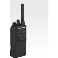
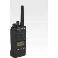
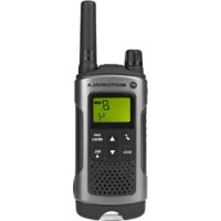
- CONTENTS
- GETTING STARTED .....29
- PROGRAMMING FEATURES ....36
- SAFETY
- PRODUCT SAFETY AND RF EXPOSURE COMPLIANCE
- ATTENTION
- INTRODUCTION
- PACKAGE CONTENTS
- BATTERIES AND CHARGERS SAFETY INFORMATION
- OPERATIONAL SAFETY GUIDELINES
- FCC LICENSING INFORMATION
- INTERFERENCE INFORMATION
- 1-800-448-6686
- RADIO OVERVIEW
- PARTS OF THE RADIO
- ON/OFF/VOLUME KNOB
- CHANNEL SELECTOR KNOB
- ACCESSORY CONNECTOR
- MODEL LABEL
- MICROPHONE
- ANTENNA
- LED INDICATOR
- SIDE BUTTONS
- PUSH-TO-TALK (PTT) BUTTON
- SIDE BUTTON 1 (SB1)
- SIDE BUTTON 2 (SB2)
- THE LITHIUM-ION (LI-ION) BATTERY
- BATTERY FEATURES
- ABOUT THE LI-ION BATTERY
- BATTERY RECYCLING AND DISPOSAL
- WWW.RBRC.COM
- 1-800-8-BATTERY
- ALKALINE BATTERY PACK (OPTIONAL ACCESSORY) INSTALLING ALKALINE BATTERIES
- REMOVING ALKALINE BATTERIES
- ATTACHING AND REMOVING ANTENNA
- ATTACHING THE ANTENNA
- REMOVING THE ANTENNA
- INSTALLING SPRING ACTION BELT CLIP
- POWER SUPPLY, ADAPTOR AND DROP-IN TRAY CHARGER
- BATTERY LIFE INFORMATION
- ALKALINE BATTERY LIFE
- NOTES
- CHARGING THE BATTERY
- CHARGING WITH THE DROP-IN TRAY SINGLE UNIT CHARGER (SUC)
- CHARGING A STANDALONE BATTERY
- CHARGING A STANDARD BATTERY
- CHARGING A HIGH CAPACITY OR ULTRA HIGH CAPACITY BATTERY
- DROP-IN TRAY CHARGER LED INDICATORS
- ESTIMATED CHARGING TIME
- CHARGING A RADIO AND BATTERY USING A MULTI UNIT CHARGER- MUC (OPTIONAL ACCESSORY)
- GETTING STARTED
- ADJUSTING VOLUME
- SELECTING A CHANNEL
- TALKING AND MONITORING
- RECEIVING A CALL
- TALK RANGE
- RADIO LED INDICATORS
- HANDS-FREE USE/VOX
- WITH COMPATIBLE VOX ACCESSORIES
- SETTING VOX SENSITIVITY
- MICROPHONE GAIN
- BATTERY SAVE
- RESET TO FACTORY DEFAULTS
- END OF TRANSMISSION TONE (ROGER BEEP TONE)
- PROGRAMMING FEATURES
- PROGRAMMING MODE
- LEARNING TO READ THE VALUES THE RADIO SIGNALS YOU
- ENTERING PROGRAMMING MODE
- READING FREQUENCIES VALUES
- READING CTCSS/DPL VALUES
- READING AUTO-SCAN VALUES
- PROGRAMMING FREQUENCIES, CODES AND AUTO-SCAN
- SAVING SETTINGS
- NOTE
- PROGRAMMING MODE FAQ
- PROGRAMMING VALUES EXAMPLE
- EXAMPLE OF PROGRAMMING A FREQUENCY
- EXAMPLE OF PROGRAMMING A CODE
- EXAMPLE OF PROGRAMMING AUTO-SCAN
- OTHER PROGRAMMING FEATURES
- SCAN
- EDITING SCAN LIST
- NUISANCE CHANNEL DELETE
- CPS (COMPUTER PROGRAMMING SOFTWARE)
- TIME-OUT TIMER
- POWER SELECT
- BATTERY TYPE SETTING
- CALL TONES
- SCRAMBLE
- REVERSE BURST
- CLONING RADIOS
- CLONING RADIO USING THE RADIO TO RADIO (R2R) CLONING CABLE (OPTIONAL ACCESSORY)
- OPERATING INSTRUCTIONS
- WHAT TO DO IF CLONING FAILS
- CLONING USING THE CPS (COMPUTER PROGRAMMING SOFTWARE)
- TROUBLESHOOTING
- USE AND CARE
- IF THE RADIO IS SUBMERGED IN WATER
- FREQUENCY AND CODE CHARTS
- RDX VHF FREQUENCIES CHART
- RDV2020 - VHF DEFAULT FREQUENCIES CHART
- RDV5100 - VHF DEFAULT FREQUENCIES CHART
- RDX UHF FREQUENCIES CHART
- RDU2020 - UHF DEFAULT FREQUENCIES CHART
- RDU4100 - UHF DEFAULT FREQUENCIES CHART
- CTCSS AND PL/DPL CODES
- PROGRAMMING CUSTOMIZED FREQUENCIES ON 4W/5W RDX MODELS
- MOTOROLA LIMITED WARRANTY FOR THE UNITED STATES AND CANADA
- WHAT DOES THIS WARRANTY COVER
- EXCLUSIONS
- USE OF NON-MOTOROLA PRODUCTS AND
- WHO IS COVERED
- HOW TO OBTAIN WARRANTY SERVICE OR OTHER INFORMATION
- SOFTWARE COPYRIGHT NOTICE
- PATENT NOTICE
- EXPORT LAW ASSURANCES
- ACCESSORIES
- ICONS CHART
- MOTOROLA
Brand : ZEBRA
Model : Rdv2020
Category : Radio