
B126-1A0-WP-1 - AV Extender Tripp Lite - Free user manual and instructions
Find the device manual for free B126-1A0-WP-1 Tripp Lite in PDF.


| Product Type | HDMI Extender (Transmitter) |
| Input Interface | 1 x HDMI (Type A Female) |
| Output Interface | 1 x RJ45 (Female, for Cat5e/6 cable) |
| Maximum Resolution | 4K@30Hz (3840x2160) |
| Transmission Distance | Up to 100 m (328 ft) over Cat6 |
| HDMI Compliance | HDMI 1.4 |
| HDCP Support | HDCP 1.4 |
| Form Factor | Wall plate (US 1-gang compatible) |
| Dimensions (H x W x D) | 4.2 x 1.7 x 1.1 in (10.7 x 4.3 x 2.8 cm) |
| Weight | 0.3 lb (0.14 kg) |
| Power Supply | External AC adapter (5V DC, 1A) |
| Power Consumption | 2.5W (max) |
| Operating Temperature | 32°F to 104°F (0°C to 40°C) |
| Storage Temperature | -4°F to 140°F (-20°C to 60°C) |
| Humidity | 10% to 85% RH (non-condensing) |
| Safety Compliance | UL, CE, RoHS |
| Installation | Insert into standard wall box; secure with screws |
| Maintenance | Wipe with dry cloth; avoid liquids |
| Spare Parts / Repairability | Not user-serviceable; contact Tripp Lite support |
Frequently Asked Questions - B126-1A0-WP-1 Tripp Lite
User questions about B126-1A0-WP-1 Tripp Lite
0 question about this device. Answer the ones you know or ask your own.
Ask a new question about this device
Download the instructions for your AV Extender in PDF format for free! Find your manual B126-1A0-WP-1 - Tripp Lite and take your electronic device back in hand. On this page are published all the documents necessary for the use of your device. B126-1A0-WP-1 by Tripp Lite.
USER MANUAL B126-1A0-WP-1 Tripp Lite
HDMI over Cat5 Extenders and Extender/Splitters
Extender Kit Models: B126-1A1 and B126-1A1-WP
Local Unit Models: B126-002 and B126-004
Remote Unit Models: B126-1P0, B126-1P0-MINI,
B126-1P0-WP-1, B126-1A0, B126-1A0-WP-1 and B126-110
Register your product for quicker service and ultimate peace of mind.
You could also win an ISOBAR6ULTRA surge protector—a \$100 value!
www.tripplite.com/warranty


Manufacturing Excellence.
1111 W. 35th Street, Chicago, IL 60609 USA • www.tripplite.com/support
Copyright © 2017 Tripp Lite. All rights reserved.
Package Contents
| B126-1A1 | B126-1A1-WP | B126-002 | B126-004 | B126-1A0 | B126-1A0-WP-1 | B126-1P0 | B126-1P0-MINI | B126-1P0-WP-1 | B126-110 | |
| Local Unit (L), Remote Unit (R) or Both (B) | B | B | L | R | R | R | R | |||
| External Power Supplies (0, 1 or 2) | 2 | 2 | 1 | 1 | 1 | 0 | 0 | 0 | 1 | |
| Mounting Hardware X X X X X | ||||||||||
| Wall Plate Screws X X X | ||||||||||
| Screwdriver for Equalization Adjustment | X X | X X | X | |||||||
| HDMI Daisy-Chain Cable X | ||||||||||
| USB Micro-B Cable X |
Product Features
All
• Support a maximum video resolution of 1080p (60 Hz)
- Plug and play—no software or drivers required
• Support up to 7.1-channel surround sound audio
• HDCP and 3D compatible
Product Features
B126-1A1
• HDMI over Cat5 Active Extender Kit
- Extends a 1080i (60 Hz) signal up to 200 ft. from the source, or a 1080p (60 Hz) signal up to 150 ft. from the source
- Additional HDMI port on the local transmitter unit allows connection of local monitor
- Remote receiver unit features a built-in equalization control for video image adjustment
- Includes mounting hardware that allows both the local transmitter and remote receiver units to be wall-mounted, rack-mounted or pole-mounted
B126-1A1-WP
• HDMI over Cat5 Active Extender Wall Plate Kit
- Extends a 1080i (60 Hz) signal up to 200 ft. from the source, or a 1080p (60 Hz) signal up to 150 ft. from the source
- Remote receiver unit features a built-in equalization control for video image adjustment
- RJ45-style wall plates allow for the use of standard Cat5e/6 patch cables; 110 punchdown connection not required
B126-002
• 2-Port HDMI over Cat5 Extender/Splitter Local Transmitter Unit
- Splits an HDMI signal into two
- Works with remote/repeater and receiver units to extend an HDMI signal past the 16 ft. (5 m) distance limitation
- Includes mounting hardware that allows unit to be wall-mounted, rack-mounted or pole-mounted
Product Features
B126-004
• 4-Port HDMI over Cat5 Extender/Splitter Local Transmitter Unit
- Splits an HDMI signal into four
- Includes an additional HDMI port, which can be used to connect a local monitor or to daisy-chain additional B126-004 units (up to three units can be daisy-chained together)
- Includes HDMI cable with latching connectors for a more secure connection
- Works with remote/repeater and receiver units to extend an HDMI signal past the 16 ft. (5 m) distance limitation
- Includes mounting hardware that allows unit to be wall-mounted, rack-mounted or pole-mounted
- Up to three B126-004 units can be mounted in a B132-004-RB 1U rack-mount bracket
B126-1A0
• HDMI over Cat5 Active Extender Remote Receiver Unit
- Works with B126-002 and B126-004 extender/splitters to extend a 1080i (60 Hz) signal up to 200 ft. from the source, or a 1080p (60 Hz) signal up to 150 ft. from the source
• Built-in equalization control for video image adjustment
- Includes mounting hardware that allows the unit to be wall-mounted, rack-mounted or pole-mounted
B126-1A0-WP-1
• HDMI over Cat5 Active Extender Wall Plate
- Works with B126-002 and B126-004 extender/splitters to extend a 1080i (60 Hz) signal up to 200 ft. from the source, or a 1080p (60 Hz) signal up to 150 ft. from the source
• Built-in equalization control for video image adjustment
- RJ45-style wall plate allows for the use of standard Cat5e/6 patch cables; 110 punchdown connection not required
Product Features
B126-1P0
• HDMI over Cat5 Passive Extender Remote Receiver Unit
- Works with B126-002 and B126-004 extender/splitters to extend a 1080i (60 Hz) signal up to 100 ft. from the source, or a 1080p (60 Hz) signal up to 50 ft. from the source
• Built-in HDMI cable has latching connector for a more secure connection
• No external power required
B126-1P0-MINI
• HDMI over Cat5 Passive Extender Remote Receiver Unit (Compact)
- Works with B126-002 and B126-004 extender/splitters to extend a 1080i (60 Hz) signal up to 100 ft. from the source, or a 1080p (60 Hz) signal up to 50 ft. from the source
- Low profile and compact design allows for discreet placement
- No external power required; USB Micro-B port provides power if needed
- Includes USB Micro-B cable
B126-1P0-WP-1
• HDMI over Cat5 Passive Extender Wall Plate
- Works with B126-002 and B126-004 extender/splitters to extend a 1080i (60 Hz) signal up to 100 ft. from the source, or a 1080p (60 Hz) signal up to 50 ft. from the source
- RJ45-style wall plate allows for the use of standard Cat5e/6 patch cables; 110 punchdown connection not required
• No external power required
Product Features
B126-110
• HDMI over Cat5 Active Extender Remote/Repeater Unit
- Extends and expands an HDMI over Cat5 installation, allowing multiple monitors to be located at different points in a chain of up to 700 ft.
- Extends a 1080i (60 Hz) signal up to 175 ft., or a 1080p (60 Hz) signal up to 125 ft. from the local transmitter unit to the first remote/repeater unit in the installation
- Extends a 1080i (60 Hz) signal up to an additional 175 ft. or a 1080p (60 Hz) signal up to an additional 125 ft. from each remote/repeater unit to the next unit in the chain (in a full four-level daisychain installation, a 1080i (60 Hz) signal can be extended up to 700 ft. or a 1080p (60 Hz) signal up to 500 ft. from the source to the last remote unit in the chain)
- Connect up to four remote units (three remote/repeaters and one receiver) with a monitor located at each point in the chain
• Built-in equalization control for video image adjustment
- Includes mounting hardware that allows the unit to be wall-mounted, rack-mounted or pole-mounted
Optional Accessories:
• B132-004-RB 1U Rack-Mount Bracket
• N202-Series Cat6 24 AWG Solid Wire Patch Cables
• P568-Series High-Speed HDMI Cables
Mounting Instructions (select models only)
The B126-002, B126-004, B126-1A1, B126-1A0 and B126-110 include mounting hardware that allows for a variety of mounting methods. The following images illustrate how the included mounting brackets can be attached for different installations.
Note: The B126-004 can also be mounted to a Tripp Lite B132-004-RB 1U Rack-Mount Bracket. Up to three B126-004 local units can be connected to a B132-004-RB.
Wall Mount

natural_image
Three black TRIPP-LITE HDMI OVER Cat5 EXTENDER devices with visible ports and labels, shown from different angles (no readable text beyond branding)19" Rack Mount Pole Mount

natural_image
Three black electronic devices: a trippa-lite device, a USB cable connector, and a mounted camera stand (no visible text or symbols)Standard Extender Kit Installation
Notes:
1) Test to ensure the entire installation works properly before pulling cables through ceilings/walls.
2) To achieve maximum distance and performance, use 24 AWG solid wire Cat5e/6 cable. Using stranded wire Cat5e/6 cable, or cable with a gauge (AWG) size higher than 24 AWG, will result in shorter extension distance. Higher gauge cabling, such as 26 AWG, has a more limited transmission capability than lower gauge cabling. All Tripp Lite N202-Series Cat6 cables are made with 24 AWG solid wire cabling.
3) The B126-1A1 and B126-1A1-WP are set to transmit a stereo audio signal by default. Press the Audio button on the local unit to switch to 7.1-channel surround-sound audio.
4) The installation diagram shows a B126-1A1 unit. The B126-1A1-WP installation is the same, except there is no local monitor port.

flowchart
graph TD
    A["OPTIONAL LOCAL MONITOR"] --> B["BLU-RAY"]
    B --> C["LOCAL TRANSMITTER"]
    C --> D["REMOTE RECEIVER"]
    D --> E["OUTPUT"]
    C --> F["UP to 200 ft. at 1080i (60Hz)"]
    C --> G["UP to 150 ft. at 1080p (60Hz)"]
Standard Extender Kit Installation
1 Make sure the HDMI source is powered OFF.
2 Connect the HDMI source to the INPUT port on the B126-1A1 or B126-1A1-WP local unit using a Tripp Lite P568-Series HDMI Cable.
3 Optional for B126-1A1: Connect a local monitor to the LOCAL port on the B126-1A1 local unit using a Tripp Lite P568-Series HDMI Cable.
4 Connect the external power supply to the local unit and plug it into a Tripp Lite Surge Protector, Power Distribution Unit (PDU) or Uninterruptible Power Supply (UPS). The green LED illuminates to indicate the unit is receiving power from the external power supply.
5 Using Cat5e/6 cable, connect the RJ45 port on the local unit to the RJ45 port on the remote unit.
6 Connect the external power supply to the remote unit and plug it into a Tripp Lite Surge Protector, PDU or UPS. The green LED illuminates to indicate the unit is receiving power from the external power supply. The orange LED illuminates to indicate the unit is connected to a powered ON local unit.
7 Connect the remote unit's HDMI port to a monitor using a Tripp Lite P568-Series HDMI Cable.
8 Turn on the power to the HDMI source. The orange LED on the local unit illuminates to indicate a signal is being received from the source.
9 If necessary, use the Equalization control on the remote unit to adjust the video image.
Note: An improper Equalization setting can cause the monitor not to display a picture at all. Try each Equalization setting until an acceptable picture is displayed.
Extender Kit with Remote/Repeater Installation
Notes:
1) Test to ensure the entire installation works properly before pulling cables through ceilings/walls.
2) To achieve maximum distance and performance, use 24 AWG solid wire Cat5e/6 cable. Using stranded wire Cat5e/6 cable, or cable with a gauge (AWG) size higher than 24 AWG, will result in shorter extension distance. Higher gauge cabling, such as 26 AWG, has a more limited transmission capability than lower gauge cabling. All Tripp Lite N202-Series Cat6 cables are made with 24 AWG solid wire cabling.
3) The B126-1A1 and B126-1A1-WP are set to transmit a stereo audio signal by default. Press the Audio button on the local unit to switch to 7.1-channel surround-sound audio.
4) The installation diagram shows a B126-1A1 unit. The B126-1A1-WP installation is the same, except there is no local monitor port.

flowchart
graph TD
    A["OPTIONAL LOCAL MONITOR"] --> B["BLU-RAY"]
    B --> C["B126-1A1 LOCAL TRANSMITTER"]
    C --> D["B126-110 REMOTE REPEATER"]
    D --> E["B126-110 REMOTE REPEATER"]
    E --> F["B126-110 REMOTE REPEATER"]
    F --> G["B126-1A1 REMOTE RECEIVER"]
    G --> H["Computer"]
    C --> I["Up to 175 ft. at 1080i (60Hz)"]
    C --> J["Up to 125 ft. at 1080p (60Hz)"]
    D --> K["Up to 175 ft. at 1080i (60Hz)"]
    D --> L["Up to 125 ft. at 1080p (60Hz)"]
    E --> M["Up to 175 ft. at 1080i (60Hz)"]
    E --> N["Up to 125 ft. at 1080p (60Hz)"]
1 Make sure the HDMI source is powered OFF.
2 Connect the HDMI source to the INPUT port on the B126-1A1 or B126-1A1-WP using a Tripp Lite P568-Series HDMI Cable.
3 Optional for B126-1A1: Connect a local monitor to the LOCAL HDMI port using a Tripp Lite P568-Series HDMI Cable.
Extender Kit with Remote/Repeater Installation
4 Connect the external power supply to the local unit and plug it into a Tripp Lite Surge Protector, PDU or UPS. The green LED illuminates to indicate the unit is receiving power from the external power supply.
5 Using Cat5e/6 cable, connect the RJ45 port on the local unit to the RJ45 INPUT port on the B126-110 remote/repeater unit.
6 Connect a monitor to the HDMI OUTPUT port on the remote/repeater unit using a Tripp Lite P568-Series HDMI Cable.
7 Connect the external power supply to the remote/repeater unit and plug it into a Tripp Lite Surge Protector, PDU or UPS. The green power LED and the green RJ45 LEDs illuminate to indicate the unit is receiving power.
Up to four units can be daisy-chained (three remote/repeaters and one receiver). To connect additional remote/repeater units, proceed to step 8. To finish your installation with the B126-1A1 or B126-1A1-WP remote receiver unit, proceed to step 12.
8 Using Cat5e/6 cable, connect the RJ45 OUTPUT port on the first remote/repeater unit to the RJ45 INPUT port on a second remote/repeater unit.
9 Connect a monitor to the HDMI OUTPUT port on the remote/repeater unit you just added using a Tripp Lite P568-Series HDMI Cable.
10 Connect the external power supply to the remote/repeater unit and plug it into a Tripp Lite Surge Protector, PDU or UPS. The green power LED and the green RJ45 LEDs illuminate to indicate the unit is receiving power.
11 To add a third remote/repeater unit, repeat steps 8 through 10. To finish your installation with the B126-1A1 or B126-1A1-WP remote receiver unit, proceed to step 12.
Extender Kit with Remote/Repeater Installation
12 Using Cat5e/6 cable, connect the RJ45 OUTPUT port on the last remote/repeater unit to the RJ45 INPUT port of the B126-1A1 or B126-1A1-WP remote receiver unit.
13 Connect a monitor to the HDMI OUTPUT port on the remote receiver unit using a Tripp Lite P568-Series HDMI Cable.
14 Connect the external power supply to the remote receiver unit and plug it into a Tripp Lite Surge Protector, PDU or UPS. The green LED illuminates to indicate the unit is receiving power from the external power supply. The orange LED illuminates to indicate the unit is connected to a powered ON remote/repeater unit.
15 Turn on the power to the HDMI source. The orange LED on the local unit illuminates to indicate a signal is being received from the source.
16 If necessary, use the Equalization control on the remote/repeater unit(s) and remote receiver unit to adjust the video image.
Note: An improper Equalization setting can cause the monitor not to display a picture at all. Try each Equalization setting until an acceptable picture is displayed.
Standard Extender/Splitter Installation
Notes:
1) Test to ensure the entire installation works properly before pulling cables through ceilings/walls.
2) To achieve maximum distance and performance, use 24 AWG solid wire Cat5e/6 cable. Using stranded wire Cat5e/6 cable, or cable with a gauge (AWG) size higher than 24 AWG, will result in shorter extension distance. Higher gauge cabling, such as 26 AWG, has a more limited transmission capability than lower gauge cabling. All Tripp Lite N202-Series cables are made with 24 AWG solid wire cabling.
3) The B126-002 and B126-004 are set to transmit a stereo audio signal by default. Press the Audio button on the B126-002 or B126-004 to switch to 7.1-channel surround-sound audio.
4) The installation diagram shows the B126-004 local transmitter unit. The B126-002 installation is the same except there are only two remote ports and no local monitor port.
5) External power is not usually required for the B126-1P0-MINI, but it includes a USB Micro-B port and cable to provide external power when needed. If you are not getting an image on the monitor when using the B126-1P0-MINI, connect the included USB cable between the USB Micro-B port and a power source (such as a USB charger).

1 Make sure the HDMI source is powered OFF.
2 Connect the HDMI source to the INPUT port on the B126-002 or B126-004 using a Tripp Lite P568-Series HDMI Cable.
3 Optional for B126-004: Connect an HDMI monitor to the LOCAL port on the B126-004 using a Tripp Lite P568-Series HDMI Cable.
4 Connect the external power supply to the B126-002 or B126-004 local unit and plug it into a Tripp Lite Surge Protector, PDU or UPS. The green RJ45 LEDs and the red Power LED on the B126-004, and the green RJ45 LEDs on the B126-002 will illuminate to indicate power is being received from the external power supply.
5 Using Cat5e/6 cable, connect one of the RJ45 output ports on the local unit to the RJ45 input port on a B126-1P0, B126-1P0-MINI, B126-1A0, B126-1P0-WP-1 or B126-1A0-WP-1 remote unit.
6 Repeat step 5 for each additional remote unit being connected.
7 B126-1A0 and B126-1A0-WP-1 only: Connect the external power supply to the B126-1A0 or B126-1A0-WP-1, and plug it into a Tripp Lite Surge Protector, PDU or UPS. The green and orange LEDs illuminate, with the green LED indicating the unit is receiving power from the external power supply, and the orange LED indicating the unit is connected to a powered ON local unit via Cat5e/6 cable.
8 Repeat step 7 for each additional B126-1A0 or B126-1A0-WP-1 in the installation.
9 Connect the B126-1P0 or B126-1P0-MINI HDMI connector to a monitor. Or, connect the B126-1P0-WP-1, B126-1A0 or B126-1A0-WP-1 to a monitor using a Tripp Lite P568-Series HDMI Cable. Both the green and orange RJ45 LEDs on the B126-1P0 and B126-1P0-MINI, and the green LED on the B126-1P0-WP-1, illuminate to indicate the unit is receiving power from the connected monitor.
Standard Extender/Splitter Installation
10 Repeat step 9 for each additional monitor being connected.
11 Turn on the power to the HDMI source. The orange RJ45 LEDs illuminate on the B126-002 and B126-004 to indicate the unit is receiving a signal from the source. The screen should now be displayed on the connected monitors.
12 If necessary, use the Equalization control on the B126-1A0 or B126-1A0-WP-1 to adjust the video image.
Note: An improper Equalization setting can cause the monitor not to display a picture at all. Try each Equalization setting until an acceptable picture is displayed.
Extender/Splitter with Remote/Repeater Installation
Notes:
1) Test to ensure the entire installation works properly before pulling cables through ceilings/walls.
2) To achieve maximum distance and performance, use 24 AWG solid wire Cat5e/6 cable. Using stranded wire Cat5e/6 cable, or cable with a gauge (AWG) size higher than 24 AWG, will result in shorter extension distance. Higher gauge cabling, such as 26 AWG, has a more limited transmission capability than lower gauge cabling. All Tripp Lite N202-Series Cat6 cables are made with 24 AWG solid wire cabling.
3) The B126-002 and B126-004 are set to transmit a stereo audio signal by default. Press the Audio button on the local unit to switch to 7.1-channel surround-sound audio.
4) The installation diagram shows the B126-004. The B126-002 installation will be the same, except there are only two remote ports and there is no local monitor port.

flowchart
graph TD
    A["Optional Local Monitor"] --> B["B126-004 LOCAL TRANSMITTER"]
    B --> C["BLU-RAY"]
    C --> D["B126-110 REMOTE/REPEATER"]
    D --> E["B126-110 REMOTE/REPEATER"]
    E --> F["B126-110 REMOTE/REPEATER"]
    F --> G["B126-110 REMOTE/REPEATER"]
    G --> H["B126-1A0-WP-1 REMOTE RECEIVER"]
    H --> I["B126-1A0-WP-1 REMOTE RECEIVER"]
    I --> J["B126-1A0-WP-1 REMOTE RECEIVER"]
    J --> K["B126-1A0-WP-1 REMOTE RECEIVER"]
    K --> L["B126-1A0-WP-1 REMOTE RECEIVER"]
    L --> M["B126-1A0-WP-1 REMOTE RECEIVER"]
    M --> N["B126-1A0-WP-1 REMOTE RECEIVER"]
    N --> O["B126-1A0-WP-1 REMOTE RECEIVER"]
    O --> P["B126-1A0-WP-1 REMOTE RECEIVER"]
    P --> Q["B126-1A0-WP-1 REMOTE RECEIVER"]
    Q --> R["B126-1A0-WP-1 REMOTE RECEIVER"]
    R --> S["B126-1A0-WP-1 REMOTE RECEIVER"]
    S --> T["B126-1A0-WP-1 REMOTE RECEIVER"]
    T --> U["B126-1A0-WP-1 REMOTE RECEIVER"]
    U --> V["B126-1A0-WP-1 REMOTE RECEIVER"]
    V --> W["B126-1A0-WP-1 REMOTE RECEIVER"]
    W --> X["B126-1A0-WP-1 REMOTE RECEIVER"]
    X --> Y["B126-1A0-WP-1 REMOTE RECEIVER"]
    Y --> Z["B126-1A0-WP-1 REMOTE RECEIVER"]
    Z --> AA["B126-1A0-WP-1 REMOTE RECEIVER"]
    AA --> AB["B126-1A0-WP-1 REMOTE RECEIVER"]
    AB --> AC["B126-1A0-WP-1 REMOTE RECEIVER"]
    AC --> AD["B126-1A0-WP-1 REMOTE RECEIVER"]
    AD --> AE["B126-1A0-WP-1 REMOTE RECEIVER"]
    AE --> AF["B126-1A0-WP-1 REMOTE RECEIVER"]
    AF --> AG["B126-1A0-WP-1 REMOTE RECEIVER"]
    AG --> AH["B126-1A0-WP-1 REMOTE RECEIVER"]
    AH --> AI["B126-1A0-WP-1 REMOTE RECEIVER"]
    AI --> AJ["B126-1A0-WP-1 REMOTE RECEIVER"]
    AJ --> AK["B126-1A0-WP-1 REMOTE RECEIVER"]
    AK --> AL["B126-1A0-WP-1 REMOTE RECEIVER"]
    AL --> AM["B126-1A0-WP-1 REMOTE RECEIVER"]
    AM --> AN["B126-1A0-WP-1 REMOTE RECEIVER"]
    AN --> AO["B126-1A0-WP-1 REMOTE RECEIVER"]
    AO --> AP["B126-1A0-WP-1 REMOTE RECEIVER"]
    AP --> AQ["B126-1A0-WP-1 REMOTE RECEIVER"]
    AQ --> AR["B126-1A0-WP-1 REMOTE RECEIVER"]
    AR --> AS["B126-1A0-WP-1 REMOTE RECEIVER"]
    AS --> AT["B126-1A0-WP-1 REMOTE RECEIVER"]
    AT --> AU["B126-1A0-WP-1 REMOTE RECEIVER"]
    AU --> AV["B126-1A0-WP-1 REMOTE RECEIVER"]
    AV --> AW["B126-1A0-WP-1 REMOTE RECEIVER"]
    AW --> AX["B126-1A0-WP-1 REMOTE RECEIVER"]
    AX --> AY["B126-1A0-WP-1 REMOTE RECEIVER"]
    AY --> AZ["B126-1A0-WP-1 REMOTE RECEIVER"]
    AZ --> BA["B126-1A0-WP-1 REMOTE RECEIVER"]
    BA --> BB["B126-1A0-WP-1 REMOTE RECEIVER"]
    BB --> BC["B126-1A0-WP-1 REMOTE RECEIVER"]
    AC["Up to 75 ft. at 1080i (60Hz)"]
    AD["Up to 75 ft. at 980i (60Hz)"]
    AE["Up to 75 ft. at 980i (60Hz)"]
Extender/Splitter with Remote/Repeater Installation
1 Make sure the HDMI source is powered OFF.
2 Connect the HDMI source to the INPUT port on the B126-002 or B126-004 using a Tripp Lite P568-Series HDMI Cable.
3 Optional for B126-004: Connect a local monitor to the LOCAL HDMI port using a Tripp Lite P568-Series HDMI Cable.
4 Connect the external power supply to the local unit and plug it into a Tripp Lite Surge Protector, PDU or UPS. The green RJ45 LEDs illuminate to indicate power is being received from the external power supply. An additional Red LED on the B126-004 also illuminates to indicate power is being received.
5 Using Cat5e/6 cable, connect one of the RJ45 output ports on the local unit to the RJ45 input port on the B126-110 remote/repeater unit.
6 Connect a monitor to the HDMI OUTPUT port on the remote/repeater unit using a Tripp Lite P568-Series HDMI Cable.
7 Connect the external power supply to the remote/repeater unit and plug it into a Tripp Lite Surge Protector, PDU or UPS. The green power LED and the Green RJ45 LEDs illuminate to indicate the unit is receiving power.
Up to four units can be daisy-chained (three remote/repeaters and one receiver). To connect additional remote/repeater units, proceed to step 8. To finish your installation with a B126-1A0 or B126-1A0-WP-1 remote receiver unit, proceed to step 12.
8 Using Cat5e/6 cable, connect the RJ45 OUTPUT port on the first remote/repeater unit to the RJ45 INPUT port on a second remote/repeater unit.
9 Connect a monitor to the HDMI OUTPUT port on the remote/repeater unit that you just added using a Tripp Lite P568-Series HDMI Cable.
Extender/Splitter with Remote/Repeater Installation
10 Connect the external power supply to the remote/repeater unit and plug it into a Tripp Lite Surge Protector, PDU or UPS. The green power LED and the green RJ45 LEDs illuminate to indicate the unit is receiving power.
11 To add a third remote/repeater unit, repeat steps 8 through 10. To finish your installation with a B126-1A0 or B126-1A0-WP-1 remote receiver unit, proceed to step 12.
12 Using Cat5e/6 cable, connect the RJ45 OUTPUT port on the last remote/repeater unit to the RJ45 INPUT port on a B126-1A0 or B126-1A0-WP-1 remote receiver unit.
13 Connect a monitor to the HDMI OUTPUT port on the remote receiver unit using a Tripp Lite P568-Series HDMI Cable.
14 Connect the external power supply to the remote receiver unit and plug it into a Tripp Lite Surge Protector, PDU or UPS. The green LED illuminates to indicate the unit is receiving power from the external power supply. The orange LED illuminates to indicate the unit is connected to a powered ON remote/repeater unit.
15 Repeat steps 5 through 14 for each additional RJ45 output port on the local transmitter unit.
16 Turn on the power to the HDMI source. The orange RJ45 LEDs on the local unit illuminate to indicate a signal is being received from the source.
17 If necessary, use the Equalization control on the remote/repeater unit(s) and remote receiver unit to adjust the video image.
Note: An improper Equalization setting can cause the monitor not to display a picture at all. Try each Equalization setting until an acceptable picture is displayed.
Extender/Splitter Daisy-Chain Installation (B126-004 only)
Notes:
1) Test to ensure the entire installation works properly before pulling cables through ceilings/walls.
2) To achieve maximum distance and performance, use 24 AWG solid wire Cat5e/6 cable. Using stranded wire Cat5e/6 cable, or cable with a gauge (AWG) size higher than 24 AWG, will result in shorter extension distance. Higher gauge cabling, such as 26 AWG, has a more limited transmission capability than lower gauge cabling. All Tripp Lite N202-Series cables are made with 24 AWG solid wire cabling.
3) The B126-004 is set to transmit a stereo audio signal by default. Press the Audio button on the B126-004 to switch to 7.1-channel surround-sound audio.
4) Using the B126-1A0 and B126-1A0-WP-1, a 1080i (60 Hz) signal can be extended up to 200 ft. from the source, or a 1080p (60 Hz) signal up to 150 ft. from the source. Using a B126-1P0, B126-1P0-MINI or B126-1P0-WP-1, a 1080i (60Hz) signal can be extended up to 100 ft. from the source, or a 1080p (60Hz) signal up to 50 ft.
Extender/Splitter Daisy-Chain Installation (B126-004 only)

Extender/Splitter Daisy-Chain Installation (B126-004 only)
1 Make sure the HDMI source is powered OFF.
2 Connect the HDMI source to the INPUT port on the B126-004 using a Tripp Lite P568-Series HDMI Cable.
3 Connect the LOCAL port on the B126-004 to the INPUT port on a second B126-004 using the included 1 ft. HDMI daisy-chain cable.
4 Repeat step 3 if connecting a third B126-004.
5 Optional: Connect a local monitor to the LOCAL HDMI port of the last B126-004 using a Tripp Lite P568-series HDMI cable.
6 Connect the external power supply to the first B126-004 in the daisy-chain and plug it into a Tripp Lite Surge Protector, PDU or UPS. The green RJ45 LEDs and the red Power LED on the B126-004 will illuminate to indicate power is being received from the external power supply.
7 Repeat step 6 for each additional B126-004 in the daisy chain.
8 Using Cat5e/6 cable, connect one of the RJ45 output ports on the local unit to the RJ45 input port on a B126-1P0, B126-1P0-MINI, B126-1A0, B126-1P0-WP-1 or B126-1A0-WP-1 remote unit.
9 Repeat step 8 for each additional remote unit being connected.
10 B126-1A0 and B126-1A0-WP-1 only: Connect the external power supply to the B126-1A0 or B126-1A0-WP-1, and plug it into a Tripp Lite Surge Protector, PDU or UPS. The green and orange LEDs illuminate, with the green LED indicating the unit is receiving power from the external power supply and the orange LED indicating the unit is connected to a powered ON local unit via Cat5e/6 cable.
11 Repeat step 10 for each additional B126-1A0 or B126-1A0-WP-1 in the installation.
Extender/Splitter Daisy-Chain Installation (B126-004 only)
12 Connect the B126-1P0 or B126-1P0-MINI HDMI connector to a monitor. Or, connect the B126-1P0-WP-1, B126-1A0 or B126-1A0-WP-1 to a monitor using a Tripp Lite P568-Series HDMI Cable. Both the green and orange RJ45 LEDs on the B126-1P0 and B126-1P0-MINI, and the green LED on the B126-1P0-WP-1, illuminate to indicate the unit is receiving power from the connected monitor.
13 Repeat step 12 for each additional monitor you are connecting.
14 Turn on the power to the HDMI source. The orange RJ45 LEDs illuminate on the B126-004 to indicate the unit is receiving a signal from the source. The screen should now be displayed on the connected monitors.
15 If necessary, use the Equalization control on the B126-1A0 or B126-1A0-WP-1 to adjust the video image.
Note: An improper Equalization setting can cause the monitor not to display a picture at all. Try each Equalization setting until an acceptable picture is displayed.
Extender/Splitter Daisy-Chain with Remote/Repeater Installation (B126-004 only)
Notes:
1) Test to ensure the entire installation works properly before pulling cables through ceilings/walls.
2) To achieve maximum distance and performance, use 24 AWG solid wire Cat5e/6 cable. Using stranded wire Cat5e/6 cable, or cable with a gauge (AWG) size higher than 24 AWG, will result in shorter extension distance. Higher gauge cabling, such as 26 AWG, has a more limited transmission capability than lower gauge cabling. All Tripp Lite N202-Series Cat6 cables are made with 24 AWG solid wire cabling.
3) The B126-004 is set to transmit a stereo audio signal by default. Press the Audio button on the local unit to switch to 7.1-channel surround-sound audio.
Extender/Splitter Daisy-Chain with Remote/Repeater Installation (B126-004 only)
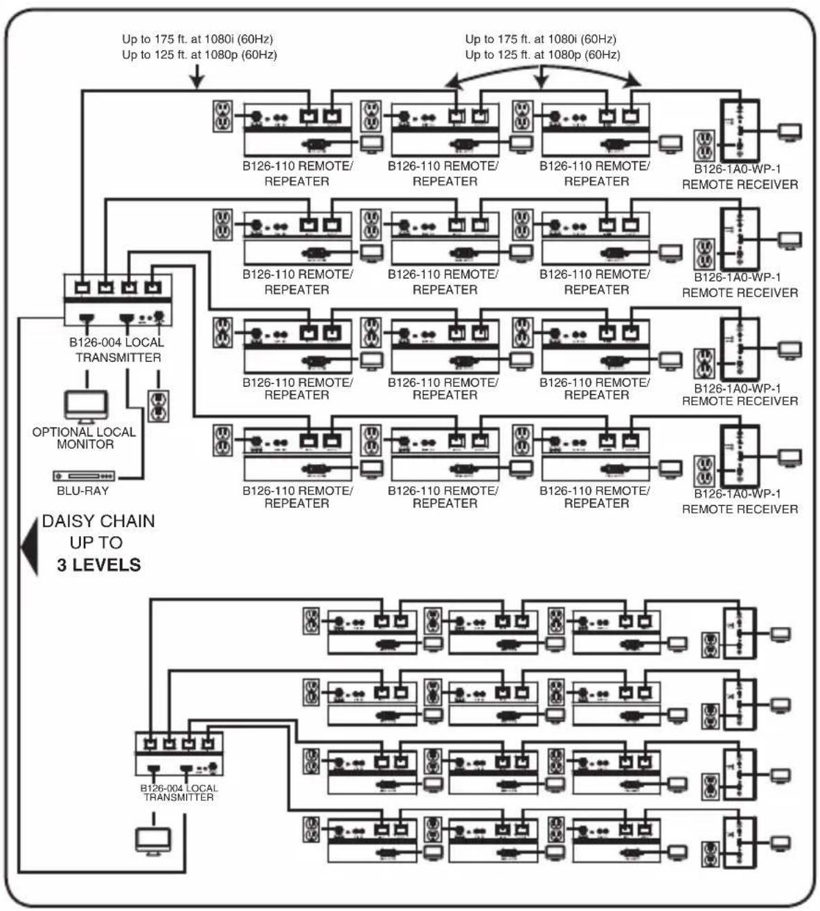
flowchart
graph TD
    subgraph DAISY_CHAIN_UP_TO_3_LEVELS
        direction TB
        A["Optional LOCAL MONITOR BLU-RAY"] --> B["B126-004 LOCAL TRANSMITTER"]
        B --> C["B126-110 REMOTE/REPEATER"]
        C --> D["B126-110 REMOTE/REPEATER"]
        D --> E["B126-110 REMOTE/REPEATER"]
        E --> F["B126-110 REMOTE/REPEATER"]
        F --> G["B126-110 REMOTE/REPEATER"]
        G --> H["B126-110 REMOTE/REPEATER"]
        H --> I["B126-110 REMOTE/REPEATER"]
        I --> J["B126-110 REMOTE/REPEATER"]
        J --> K["B126-110 REMOTE/REPEATER"]
        K --> L["B126-110 REMOTE/REPEATER"]
        L --> M["B126-110 REMOTE/REPEATER"]
        M --> N["B126-110 REMOTE/REPEATER"]
        N --> O["B126-110 REMOTE/REPEATER"]
        O --> P["B126-110 REMOTE/REPEATER"]
        P --> Q["B126-110 REMOTE/REPEATER"]
        Q --> R["B126-110 REMOTE/REPEATER"]
        R --> S["B126-110 REMOTE/REPEATER"]
        S --> T["B126-110 REMOTE/REPEATER"]
        T --> U["B126-110 REMOTE/REPEATER"]
        U --> V["B126-110 REMOTE/REPEATER"]
        V --> W["B126-110 REMOTE/REPEATER"]
        W --> X["B126-110 REMOTE/REPEATER"]
        X --> Y["B126-110 REMOTE/REPEATER"]
        Y --> Z["B126-110 REMOTE/REPEATER"]
        Z --> AA["B126-110 REMOTE/REPEATER"]
        AA --> AB["B126-110 REMOTE/REPEATER"]
        AB --> AC["B126-110 REMOTE/REPEATER"]
        AC --> AD["B126-110 REMOTE/REPEATER"]
        AD --> AE["B126-110 REMOTE/REPEATER"]
        AE --> AF["B126-110 REMOTE/REPEATER"]
        AF --> AG["B126-110 REMOTE/REPEATER"]
        AG --> AH["B126-110 REMOTE/REPEATER"]
        AH --> AI["B126-110 REMOTE/REPEATER"]
        AI --> AJ["B126-110 REMOTE/REPEATER"]
        AJ --> AK["B126-110 REMOTE/REPEATER"]
        AK --> AL["B126-110 REMOTE/REPEATER"]
        AL --> AM["B126-110 REMOTE/REPEATER"]
        AM --> AN["B126-110 REMOTE/REPEATER"]
        AN --> AO["B126-110 REMOTE/REPEATER"]
        AO --> AP["B126-110 REMOTE/REPEATER"]
        AP --> AQ["B126-110 REMOTE/REPEATER"]
        AQ --> AR["B126-110 REMOTE/REPEATER"]
        AR --> AS["B126-110 REMOTE/REPEATER"]
        AS --> AT["B126-110 REMOTE/REPEATER"]
        AT --> AU["B126-110 REMOTE/REPEATER"]
        AU --> AV["B126-110 REMOTE/REPEATER"]
        AV --> AW["B126-110 REMOTE/REPEATER"]
        AW --> AX["B126-110 REMOTE/REPEATER"]
        AX --> AY["B126-1A0-WP-1 REMOTE RECEIVER"]
    end
    subgraph DAISY_CHAIN_UP_TO_3_LEVELS
            direction TB
            A
            B
            AC
            AD
            AE
            AF
            AG
            AH
            AI
            AJ
            AK
            AL
            AM
            AN
            AO
            AP
            AQ
            AR
            AS
            AT
            AU
            AV
            AW
            AX
            AO
            AP
            AQ
            AR
            AS
            AT
            AU
            AV
            AW
            AX
            AO
            AP
            AQ
            AR
            AS
            AT
            AU
            AV
            AW
            AX
            AO
            AP
            AQ
            AR
            AS
            AT
            AU
            AV
            AW
            AX
            AO
            AP
            AQ
Extender/Splitter Daisy-Chain with Remote/Repeater Installation (B126-004 only)
1 Make sure the HDMI source is powered OFF.
2 Connect the HDMI source to the INPUT port on the B126-004 using a Tripp Lite P568-Series HDMI Cable.
3 Connect the LOCAL port on the B126-004 to the INPUT port on a second B126-004 using the included 1 ft. HDMI daisy-chain cable.
4 Repeat step 3 if connecting a third B126-004.
5 Optional: Connect a local monitor to the LOCAL HDMI port of the last B126-004 using a Tripp Lite P568-series HDMI cable.
6 Connect the external power supply to the first B126-004 in the daisy-chain and plug it into a Tripp Lite Surge Protector, PDU or UPS. The green RJ45 LEDs and the red Power LED on the B126-004 will illuminate to indicate power is being received from the external power supply.
7 Repeat step 6 for each additional B126-004 in the daisy chain.
8 Using Cat5e/6 cable, connect one of the RJ45 output ports on the local unit to the RJ45 input port on the B126-110 remote/repeater unit.
9 Connect a monitor to the HDMI OUTPUT port on the remote/repeater unit using a Tripp Lite P568-Series HDMI Cable.
10 Connect the external power supply to the remote/repeater unit and plug it into a Tripp Lite Surge Protector, PDU or UPS. The green power LED and the green RJ45 LEDs illuminate to indicate the unit is receiving power.
Up to four units can be daisy-chained (three remote/repeaters and one receiver). To connect additional remote/repeater units, proceed to step 11. To finish your installation with a B126-1A0 or B126-1A0-WP-1 remote receiver unit, proceed to step 15.
Extender/Splitter Daisy-Chain with Remote/Repeater Installation (B126-004 only)
1.1 Using Cat5e/6 cable, connect the RJ45 OUTPUT port on the first remote/repeater unit to the RJ45 INPUT port on a second remote/repeater unit.
12 Connect a monitor to the HDMI OUTPUT port on the remote/repeater unit that you just added using a Tripp Lite P568-Series HDMI Cable.
13 Connect the external power supply to the remote/repeater unit and plug it into a Tripp Lite Surge Protector, PDU or UPS. The green power LED and the green RJ45 LEDs illuminate to indicate the unit is receiving power.
14 To add a third remote/repeater unit, repeat steps 11 through 13. To finish your installation with a B126-1A0 or B126-1A0-WP-1 remote receiver unit, proceed to step 15.
15 Using Cat5e/6 cable, connect the RJ45 OUTPUT port on the last remote/repeater unit to the RJ45 INPUT port on a B126-1A0 or B126-1A0-WP-1 remote receiver unit.
16 Connect a monitor to the HDMI OUTPUT port on the remote receiver unit using a Tripp Lite P568-Series HDMI Cable.
17 Connect the external power supply to the remote receiver unit and plug it into a Tripp Lite Surge Protector, PDU or UPS. The green LED illuminates to indicate the unit is receiving power from the external power supply. The orange LED illuminates to indicate the unit is connected to a powered ON remote/repeater unit.
18 Repeat steps 8 through 17 for each additional RJ45 output port on the local transmitter units.
19 Turn on the power to the HDMI source. The orange RJ45 LEDs on the local units illuminate to indicate a signal is being received from the source.
Extender/Splitter Daisy-Chain with Remote/Repeater Installation (B126-004 only)
20 If necessary, use the Equalization control on the remote/repeater unit(s) and remote receiver unit to adjust the video image.
Note: An improper Equalization setting can cause the monitor not to display a picture at all. Try each Equalization setting until an acceptable picture is displayed.
Warranty and Product Registration
1-Year Limited Warranty
TRIPP LITE warrants its products to be free from defects in materials and workmanship for a period of one (1) year from the date of initial purchase. TRIPP LITE's obligation under this warranty is limited to repairing or replacing (at its sole option) any such defective products. To obtain service under this warranty, you must obtain a Returned Material Authorization (RMA) number from TRIPP LITE or an authorized TRIPP LITE service center. Products must be returned to TRIPP LITE or an authorized TRIPP LITE service center with transportation charges prepaid and must be accompanied by a brief description of the problem encountered and proof of date and place of purchase. This warranty does not apply to equipment which has been damaged by accident, negligence or misapplication or has been altered or modified in any way.
EXCEPT AS PROVIDED HEREIN, TRIPP LITE MAKES NO WARRANTIES, EXPRESS OR IMPLIED, INCLUDING WARRANTIES OF MERCHANTABILITY AND FITNESS FOR A PARTICULAR PURPOSE. Some states do not permit limitation or exclusion of implied warranties; therefore, the aforesaid limitation(s) or exclusion(s) may not apply to the purchaser.
EXCEPT AS PROVIDED ABOVE, IN NO EVENT WILL TRIPP LITE BE LIABLE FOR DIRECT, INDIRECT, SPECIAL, INCIDENTAL OR CONSEQUENTIAL DAMAGES ARISING OUT OF THE USE OF THIS PRODUCT, EVEN IF ADVISED OF THE POSSIBILITY OF SUCH DAMAGE. Specifically, TRIPP LITE is not liable for any costs, such as lost profits or revenue, loss of equipment, loss of use of equipment, loss of software, loss of data, costs of substitutes, claims by third parties, or otherwise.
PRODUCT REGISTRATION
Visit www.triplite.com/warranty today to register your new Tripp Lite product. You'll be automatically entered into a drawing for a chance to win a FREE Tripp Lite product!*
* No purchase necessary. Void where prohibited. Some restrictions apply. See website for details.
WEEE Compliance Information for Tripp Lite Customers and Recyclers (European Union)

Under the Waste Electrical and Electronic Equipment (WEEE) Directive and implementing regulations, when customers buy new electrical and electronic equipment from Tripp Lite they are entitled to:
- Send old equipment for recycling on a one-for-one, like-for-like basis (this varies depending on the country)
- Send the new equipment back for recycling when this ultimately becomes waste
WARNING
Use of this equipment in life support applications where failure of this equipment can reasonably be expected to cause the failure of the life support equipment or to significantly affect its safety or effectiveness is not recommended.
Tripp Lite has a policy of continuous improvement. Specifications are subject to change without notice.


1111 W. 35th Street, Chicago, IL 60609 USA • www.tripplite.com/support


- HDMI over Cat5 Extenders and Extender/Splitters
- Product Features
- All
- B126-1A1
- B126-1A1-WP
- B126-002
- B126-004
- B126-1A0
- B126-1A0-WP-1
- B126-1P0
- B126-1P0-MINI
- B126-1P0-WP-1
- B126-110
- Optional Accessories:
- Mounting Instructions (select models only)
- Standard Extender Kit Installation
- Notes:
- Extender Kit with Remote/Repeater Installation
- Standard Extender/Splitter Installation
- Extender/Splitter with Remote/Repeater Installation
- Extender/Splitter Daisy-Chain Installation (B126-004 only)
- Extender/Splitter Daisy-Chain with Remote/Repeater Installation (B126-004 only)
- Warranty and Product Registration
- 1-Year Limited Warranty
- PRODUCT REGISTRATION
- WEEE Compliance Information for Tripp Lite Customers and Recyclers (European Union)
- WARNING
Brand : Tripp Lite
Model : B126-1A0-WP-1
Category : AV Extender