
UGT-CR960 - Memory reader Vantec - Free user manual and instructions
Find the device manual for free UGT-CR960 Vantec in PDF.


| Product Type | Memory Card Reader |
| Brand | Vantec |
| Model | UGT-CR960 |
| Interface | USB 3.0 (USB 2.0 compatible) |
| Supported Card Types | SD, SDHC, SDXC, microSD, microSDHC, microSDXC, CompactFlash (CF), Memory Stick (MS), MS Duo, MS Pro, xD-Picture Card |
| Number of Card Slots | Multiple (typically 3-4) |
| Dimensions (L x W x H) | Approx. 95 x 50 x 15 mm |
| Weight | Approx. 50 g |
| Power Supply | Bus-powered via USB |
| LED Indicator | Yes (power/activity) |
| Operating Systems Supported | Windows, macOS, Linux (driverless for most cards) |
| Transfer Speed | Up to 5 Gbps (USB 3.0) |
| Maintenance | Wipe with a soft, dry cloth; avoid liquids |
| Material | Plastic enclosure |
| Package Contents | Card reader, USB cable, user manual |
Frequently Asked Questions - UGT-CR960 Vantec
User questions about UGT-CR960 Vantec
0 question about this device. Answer the ones you know or ask your own.
Ask a new question about this device
Download the instructions for your Memory reader in PDF format for free! Find your manual UGT-CR960 - Vantec and take your electronic device back in hand. On this page are published all the documents necessary for the use of your device. UGT-CR960 by Vantec.
USER MANUAL UGT-CR960 Vantec
Multi-Memory Internal Card Reader w/ USB2.0, eSATA, Audio Ports
Model No.: UGT-CR960
Installation Guide
v1.02
System Requirement
• Microsoft Windows XP/Vista/7(32/64 Bit)
- Mac OS x 10.4+
Package Content
• Vantec Multi-Memory Internal Card Reader w/USB2.0, eSATA, Audio Ports
• 3.5" to 5.25" Mounting Bracket
- Installation Guide
- Installation Screws
Bracket Installation instructions

natural_image
Metal bracket with two circular holes, no text or symbols visibleLeft

natural_image
Metal bracket with two circular holes, no text or symbols visibleRight
- Step 1: See above, distinguish metal plates installed for left and right.

natural_image
Close-up of a black electronic device with a metallic mounting bracket and a small circular button (no visible text or symbols)
natural_image
Close-up of a black electronic device with a metallic mounting bracket and ventilation slots (no visible text or symbols)- Step 2: Install the screws to card reader, both left and right (refer to above photo)
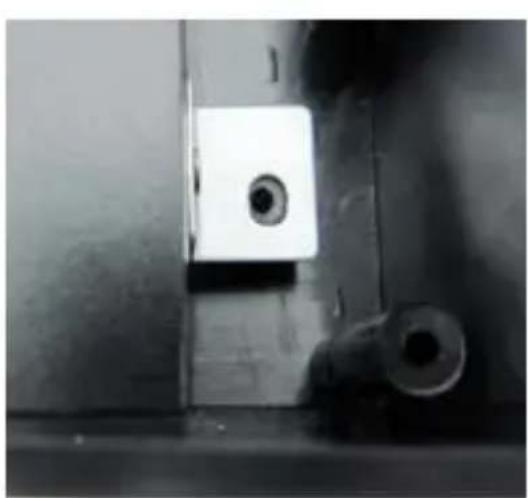
natural_image
Close-up of a metallic mechanical component with a central square and two circular holes (no visible text or symbols)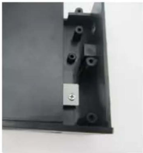
natural_image
Close-up of a black metal bracket with multiple bolt holes and a small metallic component (no visible text or symbols)Step 3: Put the card reader inside the bracket, tighten the screws.
Step 4: Finish

natural_image
Black electronic device with attached cables and ports, no visible text or symbolsInstallation of product
If in doubt about how to install the device correctly, please contact an EXPERT or a specialist workshop and let them do the installation! Improper installation can damage the plug-in unit as well as your computer and all connected devices.
Proceed with caution. Danger to life!
Switch off the computer in which the product is to be installed and all connected devices. Disconnect all devices from the mains voltage and pull out the main AC power cord! Just turning off at the on/off switch is not enough!
- Open your computer's housing and carefully remove the cover.
- Look for a free 3.5" installation slot and remove the slot cover.
Often there is a metal shielding behind it, which has to be removed first. With some casings, you have to unscrew this, with others you have to break it out carefully. Depending on the casing, you may have to remove the entire front cover first.
- Apart from the slot cover that is already mounted on the slot, the scope of delivery includes two more front covers in different colours. Depending on the existing computer housing, the slot cover can easily be replaced by another one.
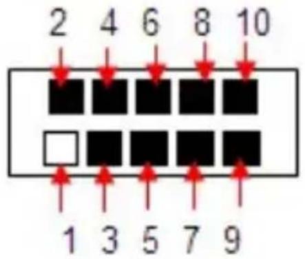
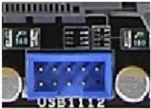
- Connect the 9-pin USB plugs to an internal USB ports on the motherboard. It is imperative to observe the correct orientation (see operating instructions for the motherboard) since a wrong connection may damage both the motherboard and the electronics of the 3.5"plug-in unit, loss of warranty (refer to below photo)!

natural_image
Close-up of a black plastic electrical connector with multiple slots and three connectors (no visible text or symbols)-9pin USB plug
natural_image
Close-up of a blue electronic component with gold pins and circuit board (no readable text or symbols)-USB 9pin pinouts
Most motherboard use cable pinout, some motherboard have slot for fixing it
| 1.□ Annual | 3.■ GND(Gray) | 5.■ DATA+(Brown) | 7.■ DATA-(Yellow) | 9.■ VCC(Orange) |
| 2.■ GND | 4.■ GND(Black) | 6.■ DATA+(Green) | 8.■ DATA-(White) | 10.■ VCC(Red) |
(USB cable pinout)
- Connect the Audio plug connector with a free Audio connection of your motherboard. Please also note the operating instructions of the motherboard.(refer to below photo):


natural_image
Close-up of a computer motherboard with visible pinout and circuit layout (no readable text or symbols)
natural_image
Grid of black squares with one white square in the bottom-right cell (no text or symbols)-Audio Plug
-Audio pinout
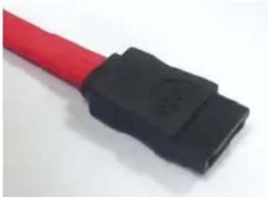
- Connect the SATA plug connector with a free SATA connection of your motherboard. Please also note the operating instructions of the motherboard. (Refer to below photo)
natural_image
Close-up of a red and black electrical connector (no text or symbols visible)-Red SATA cable

-SATA connector on motherboard
- Install the cables so that they do not protrude into any of the computer's fan, use cable ties, for example.
- Close the computer housing.
- Connect your computer and monitor to the mains voltage and switch on all devices.
- If your computer does not start correctly, switch it off again immediately and check all the settings and cable connections. It must be disconnected from the mains power supply before restarting, see above!
UGT-CR960

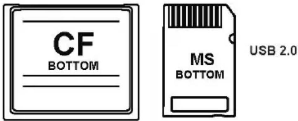
Memory card direction

Warranty:
The Multi-Memory Internal Card Reader w/USB2.0, eSATA, Audio Ports comes with a 1 year limited warranty. If your unit should become defective within that time frame, please go to
http://www.vantecusa.com for information on how to receive warranty exchange or repair. Cosmetic defects and missing parts are not covered under this warranty. Please check thecontents of the unit to make sure you received all parts. Also, check for any cosmetic flaws. If any parts are missing or if there are cosmetic defects, please contact the retailer from which you purchased the unit immediately and ask for a replacement.
Contact:
Vante Thermal Technology
www.vantecusa.com

Brand : Vantec
Model : UGT-CR960
Category : Memory reader