TF8200 A2+ - Motherboard BIOSTAR - Free user manual and instructions
Find the device manual for free TF8200 A2+ BIOSTAR in PDF.

| Product Type | Motherboard |
| Brand | Biostar |
| Model | TF8200 A2+ |
| Chipset | NVIDIA GeForce 8200 |
| CPU Socket | Socket AM2/AM2+ |
| Supported Processors | AMD Phenom, Athlon 64, Sempron |
| Memory Type | DDR2 |
| Maximum Memory | 8 GB |
| Form Factor | Micro ATX |
| Dimensions (W x H) | 24.4 cm x 24.4 cm |
| Weight | Approximately 0.6 kg |
| Power Requirement | ATX power supply (24-pin main connector) |
| Expansion Slots | 1 x PCIe x16, 1 x PCIe x1, 2 x PCI |
| Storage Interfaces | 6 x SATA II (3 Gb/s), 1 x IDE |
| USB Ports | 8 x USB 2.0 (4 rear, 4 via headers) |
| Video Output | VGA, DVI, HDMI (via integrated GPU) |
| Audio | Realtek ALC888, 8-channel HD Audio |
| Networking | Realtek RTL8111C Gigabit Ethernet |
| BIOS | Award BIOS, 8 Mbit Flash ROM |
| Maintenance & Cleaning | Use canned air for dust; avoid liquids. Reapply thermal paste if CPU is removed. |
| Safety | Disconnect power before installation. Handle with anti-static precautions. |
| Spare Parts & Repairability | Standard ATX components; CMOS battery CR2032 easily replaceable. Contact Biostar for other parts. |
| General Information | Designed for AMD multi-core processors with integrated NVIDIA GeForce 8200 graphics. |
Frequently Asked Questions - TF8200 A2+ BIOSTAR
User questions about TF8200 A2+ BIOSTAR
0 question about this device. Answer the ones you know or ask your own.
Ask a new question about this device
Download the instructions for your Motherboard in PDF format for free! Find your manual TF8200 A2+ - BIOSTAR and take your electronic device back in hand. On this page are published all the documents necessary for the use of your device. TF8200 A2+ by BIOSTAR.
USER MANUAL TF8200 A2+ BIOSTAR
FCC Information and Copyright
This equipment has been tested and found to comply with the limits of a Class B digital device, pursuant to Part 15 of the FCC Rules. These limits are designed to provide reasonable protection against harmful interference in a residential installation. This equipment generates, uses, and can radiate radio frequency energy and, if not installed and used in accordance with the instructions, may cause harmful interference to radio communications. There is no guarantee that interference will not occur in a particular installation.
The vendor makes no representations or warranties with respect to the contents here and specially disclaims any implied warranties of merchantability or fitness for any purpose. Further the vendor reserves the right to revise this publication and to make changes to the contents here without obligation to notify any party beforehand.
Duplication of this publication, in part or in whole, is not allowed without first obtaining the vendor's approval in writing.
The content of this user's manual is subject to be changed without notice and we will not be responsible for any mistakes found in this user's manual. All the brand and product names are trademarks of their respective companies.
Table of Contents
Chapter 1: Introduction....1
1.1 Before You Start 1
1.2 Package Checklist....1
1.3 Motherboard Features....2
1.4 Rear Panel Connectors 4
1.5 Motherboard Layout....5
Chapter 2: Hardware Installation ...... 6
2.1 Installing Central Processing Unit (CPU) 6
2.2 FAN Headers....8
2.3 Installing System Memory 9
2.4 Connectors and Slots 11
Chapter 3: Headers & Jumpers Setup 13
3.1 How to Setup Jumpers 13
3.2 Detail Settings....13
Chapter 4: NVIDIA RAID Functions ...... 21
4.1 Operation System 21
4.2 Raid Arrays 21
4.3 How RAID Works 21
Chapter 5: T-Series BIOS & Software 25
5.1 T-Series BIOS 25
5.2 T-Series Software 33
Chapter 6: Useful Help ...... 42
6.1 Driver Installation Note 42
6.2 Extra Information....43
6.3 AMI BIOS Beep Code 44
6.4 Troubleshooting.... 45
Appendencies: SPEC In Other Language 46
German....46
France 48
Italian....50
Spanish 52
Portuguese 54
Polish....56
Russian 58
Arabic....60
Japanese 62
CHAPTER 1: INTRODUCTION
1.1 B EFORE YOU START
Thank you for choosing our product. Before you start installing the motherboard, please make sure you follow the instructions below:
■ Prepare a dry and stable working environment with sufficient lighting.
■ Always disconnect the computer from power outlet before operation.
■ Before you take the motherboard out from anti-static bag, ground yourself properly by touching any safely grounded appliance, or use grounded wrist strap to remove the static charge.
■ Avoid touching the components on motherboard or the rear side of the board unless necessary. Hold the board on the edge, do not try to bend or flex the board.
■ Do not leave any unfastened small parts inside the case after installation. Loose parts will cause short circuits which may damage the equipment.
- Keep the computer from dangerous area, such as heat source, humid air and water.
1.2 PACKAGE CHECKLIST
HDD Cable X 1
Serial ATA Cable X 2
Serial ATA Power Cable X 1
Rear I/O Panel for ATX Case X 1
User's Manual X 1
Fully Setup Driver CD X 1
FDD Cable X 1 (optional)
USB 2.0 Cable X1 (optional)
S/PDIF out Cable X 1 (optional)
Note: The package contents may differ by area or your motherboard version.
1.3 MOTHERBOARD FEATURES
| SPEC | ||
| CPU | Socket AM2+AMD Athlon 64 / Athlon 64 FX/ Athlon 64 x2 / Sempron / Pheno m processors | AMD 64 Architecture enables 32 and 64 bit computingSupports Hyper Transport 3.0 and Cooln'Quiet |
| FSB | Support HyperTransport 3.0Supports up to 5.2 GT/s Bandwidth | |
| Chipset | GeForce 8200 | |
| Super I/O | ITE 8718FProvides the most commonly used legacySuper I/O functionality.Low Pin Count Interface | Environment Control in it iatives,H/W MonitorFan Speed ControllerITE's "Smart Guard ian" funct ion |
| MainMemory | DIMM Slots x 4Each DIMM supports 256MB/512MB/1GB/2GB/4GB DDR2Max Memory Capicity 16GB | Dual Channel Mode DDR2 memory moduleSupports DDR2 533 / 667 / 800Supports DDR2 1066 (by AM2+ CPU)Registered DIMM and ECC DIMM is not supported |
| Graphics Integrated in GeForce 8200 Chipset | Max Shared Video Memory is 512 MBDX10 / HDCP / PureV ideo support | |
| IDE | Integrated IDE | Ultra DMA 33 / 66 / 100 / 133 Bus Master Modersupports PIO Mode 0~4 |
| SATA II Integrated Serial ATA Controller | Data transfer rates up to 3 Gb/s.SATA Version 2.0 specif ic at ion co mp liant. | |
| LAN Realtek | RTL 8111C | 10 / 100 / 1000 Mb/s auto negotiationHalf / Full duplex capability |
| Sound | ALC888S /Integrated in GeForce 8200 (for HDMI Audio) | 7.1 channels audio out (ALC888S)2 channels audio out (for HDMI Audio)Supports HD Audio |
| Slots | PCI slot x3 Supports PCI expansion cardsDVI-I Adapter slot x1 Supports specified DV I-I AdapterPCI Express Gen2 x16 slot x1PCI Express x1 slot x2 | Supports PCI-E Gen2 x16 expansion cardsSupports PCI-E x1 expansion cards |
| On Board Connector | Floppy connector x1 Each connector supports 2 Floppy drivesPrinter Port connector x1 Each connector supports 1 Printer portIDE Connector x1 Each connector supports 2 IDE deviceSATA Connector x6 Each connector supports 1 SATA devicesFront Panel Connector x1 Supports front panel facilitiesFront Audio Connector x1 Supports front panel audio functionCD-in Connector x1 Supports CD audio-in functionS/PDIF out connector x1 Supports digital audio out functionS/PDIF in connector x1 Supports digital audio-in functionCPU Fan header x1 CPU Fan power supply (with Smart Fan function)System Fan header x2 System Fan Power supplyCMOS dear header x1 Restore CMOS data to factory defaultUSB connector x4 Each connector supports 2 front panel USB portsSerial port Connector x1 Connects to RS-232 PortPower Connector (24pin) x1 Connects to Power supplyPower Connector (8pin) x1 Connects to Power supply | |
| Back Panel I/O | PS/2 Keyboard x1Connects to PS/2 KeyboardPS/2 Mouse x1Connects to PS/2 MouseLAN port x1Connect to RJ-45 ethernet cableUSB Port x4Connect to USB devicesAudio Jack x6Provide Audio-In/Out and microphone connectionDVI port x1Connect to DVI-D monitorHDMI port x1Connect to HDTVVGA port x1Connect to D-SUB monitor | |
| Board Size | 225 mm (W) x 305 mm (L) | |
| Special Features | RAID 0 / 1 / 5 / 0+1 supportHybrid SLI support (by nVIDIA driver) | |
| OS Support | Windows XP / VISTA | Biostar Reserves the right to add or remove support for any OS With or without notice. |
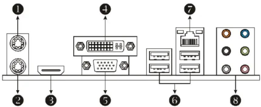
1.4 REAR PANEL CONNECTORS
flowchart
graph TD
    1["Port 1"] --> 2["Port 2"]
    2 --> 3["Port 3"]
    3 --> 4["Port 4"]
    4 --> 5["Port 5"]
    5 --> 6["Port 6"]
    6 --> 7["Port 7"]
    7 --> 8["Port 8"]
PS/2 Mouse Port
② PS/2 Keyboard Port
③ HDMI Port
The High-Definition Multimedia Interface (HDMI) is an all-digital audio/video interface capable of transmitting uncompressed streams to an AV receiver or any compatible digital audio and/or video monitor, such as a digital television.
④ DVI-D VGA Port
The Digital Visual Interface (DVI) is a video interface transmitting digital video signals to digital display devices such as flat panel LCDs or digital projectors. The DVI-D connector allows digital signals transmission only.
⑤ D-Sub VGA Port
Transmit analog video signals to computer monitor or any other display panels equipped with D-Sub VGA input.
⑥ USB 2.0 Port x 4
⑦ 10/100/1000 Mbps LAN Port
⑧ Audio Jack x 6
| Port 2-Channel | 4-Channel | 6-Channel/8-Channel | |
| Blue Line-In | Line-In | Line-In | |
| Green Line-Out Front Speaker Out Front Speaker Out | |||
| Pink Mic In Mic In Mic In | |||
| Orange | Center/S | ||
| Black | Rear Speaker Out | Rear Speaker Out | Rear Speaker Out |
| Grey | Side Speaker Out | ||
NOTE 1: The HDMI and DVI-D ports both can provide digital video signals out-put function, but these two interfaces cannot work at the same time. The chipset uses the same channel to control HDMI and DVI-D, so these ports cannot transmit video signal to different display panels simultaneously.
ubwoo
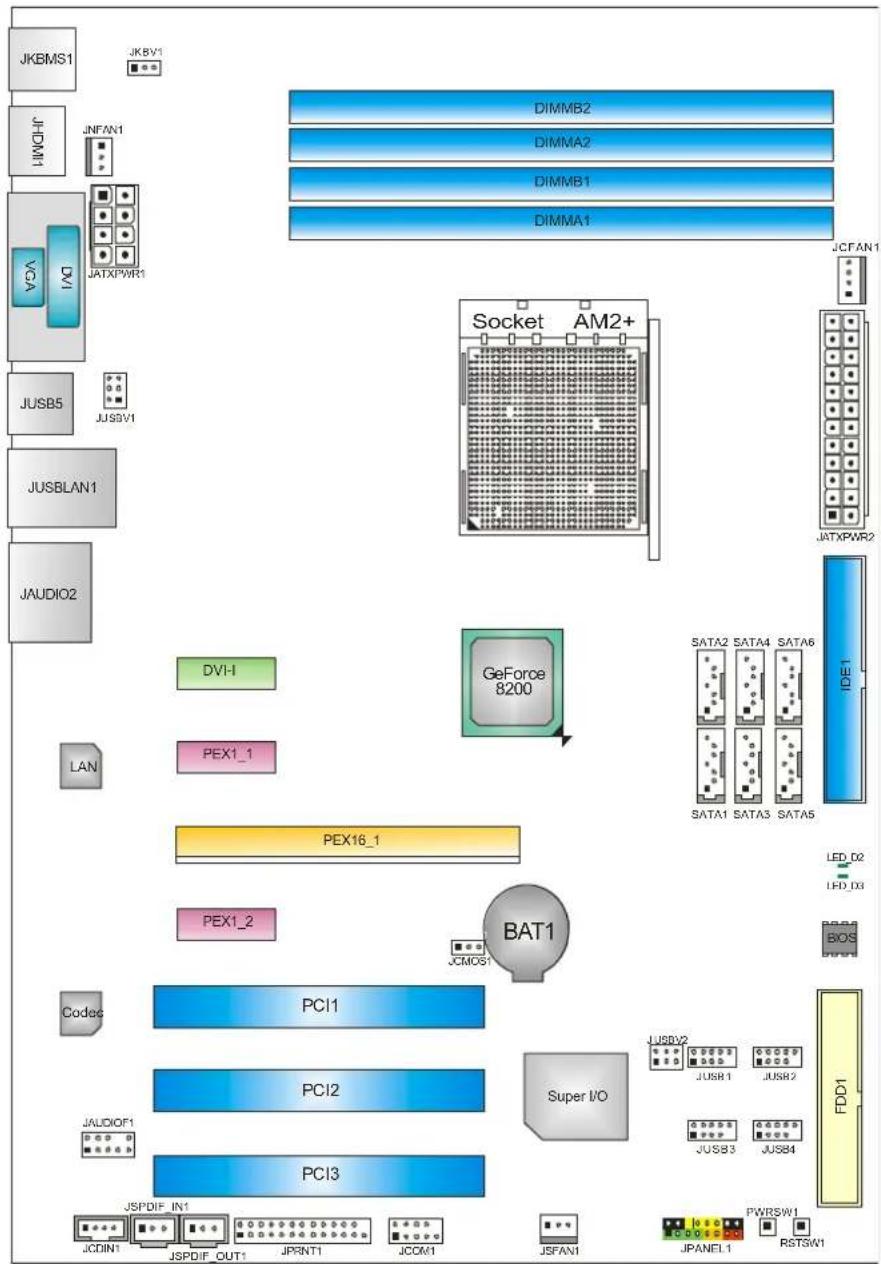
1.5 MOTHERBOARD LAYOUT
flowchart
graph TD
    A["JKBMS1"] --> B["JKBV1"]
    C["JHMI"] --> D["JNFAN1"]
    E["VC4"] --> F["JATXPWR1"]
    G["JUSB5"] --> H["JJSW1"]
    I["JUSBLAN1"] --> J["JAUDIO2"]
    K["DVI-1"] --> L["PEX1_1"]
    M["LAN"] --> N["PEX16_1"]
    O["Codec"] --> P["PCI1"]
    Q["JAUDIOF1"] --> R["PCI2"]
    S["JSPDIF_IN1"] --> T["PCI3"]
    U["JCDIN1"] --> V["JSPDIF_OUT1"]
    W["JPRINT1"] --> X["JCOM1"]
    Y["JSFAN1"] --> Z["JPANEL1"]
    AA["PWRSW1"] --> AB["RSTSW1"]
    AC["SATA2 SATA4 SATA6"] --> AD["SATA1 SATA3 SATA5"]
    AE["IDE1"] --> AF["SATA6"]
    AG["SATA2"] --> AH["AM2+"]
    AI["SATA4"] --> AJ["AM2+"]
    AK["SATA6"] --> AL["AM2+"]
    AM["SATA2"] --> AN["AM2+"]
    AO["SATA4"] --> AP["AM2+"]
    AQ["SATA6"] --> AR["AM2+"]
    AS["GEForce 8200"] --> AT["Socket"]
    AU["Socket"] --> AV["AM2+"]
    AW["JATXPWR2"] --> AX["AM2+"]
    AY["JCFAN1"] --> AZ["AM2+"]
Note: represents the 1 ^t pin.
CHAPTER 2: HARDWARE INSTALLATION
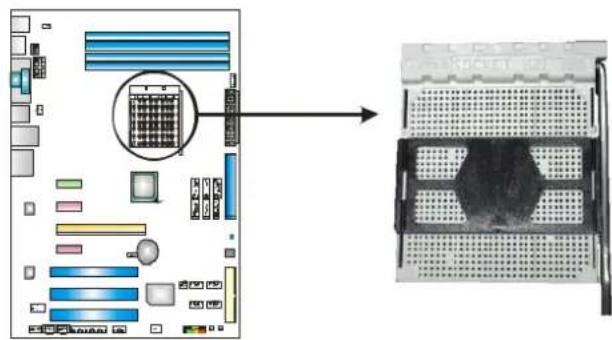
2.1 INSTALLING CENTRAL PROCESSING UNIT (CPU)
text_image
Diagram showing computer motherboard layout with a magnified view of the internal grid and rear panel structure.Step 1: Remove the socket protection cap.
natural_image
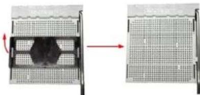
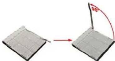
Two-panel diagram showing a meshed grid structure before and after transformation, with no visible text or symbols.Step 2: Pull the lever toward direction A from the socket and then raise the lever up to a 90-degree angle.
natural_image
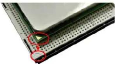
Diagram showing two rectangular blocks with a red arrow indicating transformation or movement, no text or symbols present.Step 3: Look for the white triangle on socket, and the gold triangle on CPU should point towards this white triangle. The CPU will fit only in the correct orientation.
natural_image
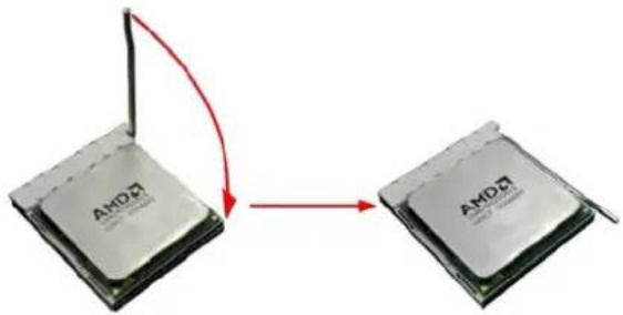
Close-up of a green electronic component mounted on a perforated base, with red circles highlighting a small component (no text or symbols visible)Step 4: Hold the CPU down firmly, and then close the lever toward direct B to complete the installation.
flowchart
graph TD
    A["AMD CPU"] -->|Red Arrow| B["AMD CPU"]
    style A fill:#f9f,stroke:#333
    style B fill:#bbf,stroke:#333
Step 5: Put the CPU Fan on the CPU and buckle it. Connect the CPU FAN power cable to the JCFAN1. This completes the installation.
Note: Please update the BIOS to the latest version while using AM2+ CPUs. Due to the latest CPU transition, you may encounter the situation that the new system failed to boot while using new AM2+ CPUs. In this case, please install one standard AM2 CPU to boot your system, and update the latest BIOS from our website for AM2+ CPUs support.
2.2 FAN HEADERS
These fan headers support cooling-fans built in the computer. The fan cable and connector may be different according to the fan manufacturer. Connect the fan cable to the connector while matching the black wire to pin#1.
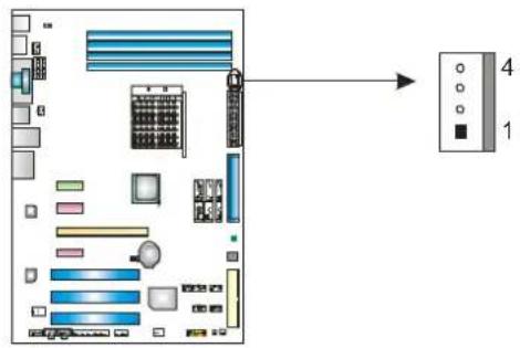
JCFAN1: CPU Fan Header
text_image
Diagram showing computer motherboard layout with labeled components and connection to a wall-mounted unit 4| Pin | Assignment |
| 1 | Ground |
| 2 | +12V |
| 3 | FAN RPM rate sense |
| 4 | Smart Fan Control (By Fan) |
JSFAN1: System Fan Header
JNFAN1: Chipset Fan Header
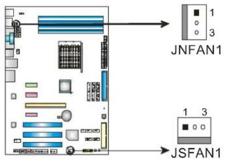
text_image
JNFAN1 JSFAN1Pin Assignment
| 1 | Ground |
| 2 | +12V |
| 3 | FAN RPM rate sense |
Note:
The JCFAN1 and JSFAN1/JNFAN1 support 4-pin and 3-pin head connectors. When connecting with wires onto connectors, please note that the red wire is the positive and should be connected to pin#2, and the black wire is Ground and should be connected to GND.
2.3 INSTALLING SYSTEM MEMORY
A. Memory Modules
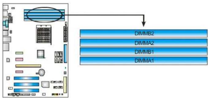
flowchart
graph TD
    A["CPU Interface"] --> B["DimMB2"]
    A --> C["DimMA2"]
    A --> D["DimMB1"]
    A --> E["DimMA1"]
- Unlock a DIMM slot by pressing the retaining clips outward. Align a DIMM on the slot such that the notch on the DIMM matches the break on the Slot.
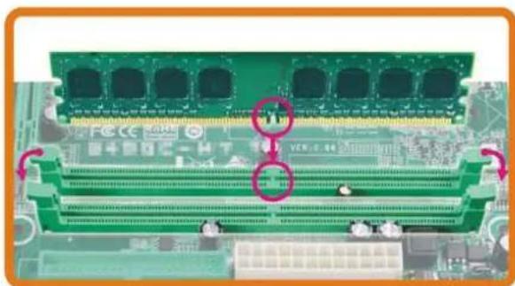
natural_image
Close-up of a green computer RAM module with multiple slots and ventilation slots, showing internal circuitry (no readable text or symbols)- Insert the DIMM vertically and firmly into the slot until the retaining chip snap back in place and the DIMM is properly seated.
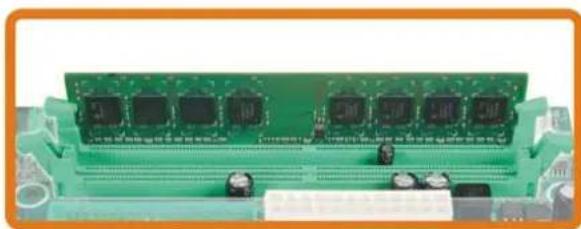
natural_image
Green printed circuit board with multiple microcontroller chips and connectors (no visible text or symbols)B. Memory Capacity
| DIMM Socket Location | DDR2 Module | Total Memory Size |
| DIMMA1 | 256MB/512MB/1GB/2GB/4GB | Max is 16GB. |
| DIMMB1 | 256MB/512MB/1GB/2GB/4GB | |
| DIMMA2 | 256MB/512MB/1GB/2GB/4GB | |
| DIMMB2 | 256MB/512MB/1GB/2GB/4GB |
C. Dual Channel Memory installation
To trigger the Dual Channel function of the motherboard, the memory module must meet the following requirements:
Install memory module of the same density in pairs, shown in the following table.
| Dual Channel Status | DIMMA1 | DIMMB1 | DIMMA2 | DIMMB2 |
| Enabled | O | O | X | X |
| Enabled | X | X | O | O |
| Enabled | O | O | O |
(O means memory installed, X means memory not installed.)
The DRAM bus width of the memory module must be the same (x8 or x16)
2.4 CONNECTORS AND SLOTS
FDD1: Floppy Disk Connector
The motherboard provides a standard floppy disk connector that supports 360K, 720K, 1.2M, 1.44M and 2.88M floppy disk types. This connector supports the provided floppy drive ribbon cables.
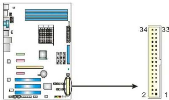
text_image
Diagram of a computer motherboard with labeled components and pin connectionsIDE1: Hard Disk Connector
The motherboard has a 32-bit Enhanced IDE Controller that provides PIO Mode 0\~4, Bus Master, and Ultra DMA 33/66/100/133 functionality.
The IDE connector can connect a master and a slave drive, so you can connect up to two hard disk drives.
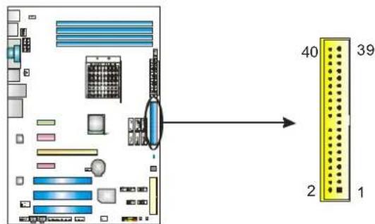
text_image
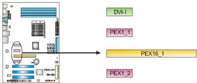
40 39 2 1PEX16\_1: PCI-Express Gen2 x16 Slot
- PCI-Express 2.0 compliant.
- Maximum theoretical realized bandwidth of 8GB/s simultaneously per direction, for an aggregate of 16GB/s totally.
- PCI-Express Gen2 supports a raw bit-rate of 5.0Gb/s on the data pins.
- 2X bandwidth over the PCI-Express 1.1 architecture.
PEX1\_1/PEX1\_2: PCI-Express x1 Slots
- PCI-Express 1.1 compliant.
- Data transfer bandwidth up to 250MB/s per direction; 500MB/s in total.
- PCI-Express supports a raw bit-rate of 2.5Gb/s on the data pins.
- 2X bandwidth over the PCI architecture.
DVI-I: M.D.V Card Slot
- This is a unique slot for the specified M.D.V Card.
flowchart
graph TD
    A["Data Bus"] --> B["Processing Unit"]
    B --> C["DVI-I"]
    B --> D["PEX1_1"]
    B --> E["PEX16_1"]
    B --> F["PEX1_2"]
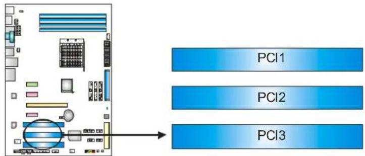
PCI1\~PCI3: Peripheral Component Interconnect Slots
This motherboard is equipped with 3 standard PCI slots. PCI stands for Peripheral Component Interconnect, and it is a bus standard for expansion cards. This PCI slot is designated as 32 bits.
flowchart
graph TD
    A["PC1"] --> B["Data Flow"]
    C["PC2"] --> B
    D["PC3"] --> B
    B --> E["Output"]
CHAPTER 3: HEADERS & JUMPERS SETUP
3.1 HOW TO SETUP JUMPERS
The illustration shows how to set up jumpers. When the jumper cap is placed on pins, the jumper is "close", if not, that means the jumper is "open".
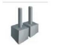
Pin
opened
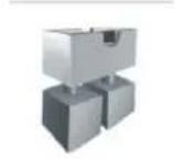
Pin
closed
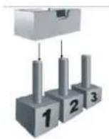
Pin1-2
closed
3.2 DETAIL SETTINGS
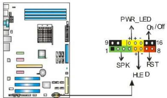
JPANEL1: Front Panel Header
This 16-pin connector includes Power-on, Reset, HDD LED, Power LED, and speaker connection. It allows user to connect the PC case's front panel switch functions.
text_image
PWR_LED On/Off 9 16 8 SPK RST HLED| Pin | Assignment | Function | Pin | Assignment | Function |
| 1 | +5V | Speaker Connector | 9 | N/A | N/A |
| 2 | N/A | 10 | N/A | ||
| 3 | N/A | 11 | N/A | N/A | |
| 4 | Speaker | 12 | Power LED (+) | Power LED | |
| 5 | HDD LED (+) | Hard drive LED | 13 | Power LED (+) | |
| 6 | HDD LED (-) | 14 | Power LED (-) | ||
| 7 | Ground | Reset button | 15 | Power button | Power-on button |
| 8 | Reset control | 16 | Ground |
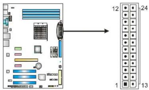
JATXPWR2: ATX Power Source Connector
This connector allows user to connect 24-pin power connector on the ATX power supply.
text_image
Diagram of a computer motherboard with labeled components and numbered connectors| Pin | Assignment | Pin | Assignment | |||
| 13 | +3.3V | 1 | +3.3V | |||
| 14 | -12V | 2 | +3.3V | |||
| 15 | Gro | und | 3 | Gro | und | |
| 16 | PS_ON | 4 | +5V | |||
| 17 | Gro | und | 5 | Gro | und | |
| 18 | Ground | 6 | +5V | |||
| 19 | Gro | und | 7 | Gro | und | |
| 20 | NC | 8 | PW_OK | |||
| 21 | +5V | 9 | Standby | Voltage+5V | ||
| 22 | +5V | 10 | +12V | |||
| 23 | +5V | 11 | +12V | |||
| 24 | Ground | 12 | +3.3V | |||
JATXPWR1: ATX Power Source Connector
By connecting this connector, it will provide +12V to CPU power circuit.
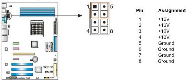
text_image
Pin Assignment 1 +12V 2 +12V 3 +12V 4 +12V 5 Ground 6 Ground 7 Ground 8 GroundNote:
Before power on the system, please make sure that both JATXPWR1 and JATXPWR2 connectors have been plugged-in.
If the CPU power plug is 4-pin, please plug it into Pin 1-2-5-6 of JATXPWR1.
JUSB1\~JUSB4: Headers for USB 2.0 Ports at Front Panel
This header allows user to connect additional USB cable on the PC front panel, and also can be connected with internal USB devices, like USB card reader.
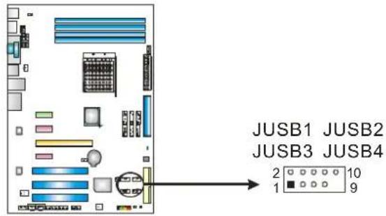
text_image
JUSB1 JUSB2 JUSB3 JUSB4 2 10 1 9| Pin | Assignment | |
| 1 | +5V | (fused) |
| 2 | +5V | (fused) |
| 3 | USB- | |
| 4 | USB- | |
| 5 | USB+ | |
| 6 | USB+ | |
| 7 | Ground | |
| 8 | Ground | |
| 9 | Key | |
| 10 | NC | |
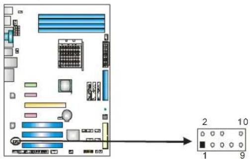
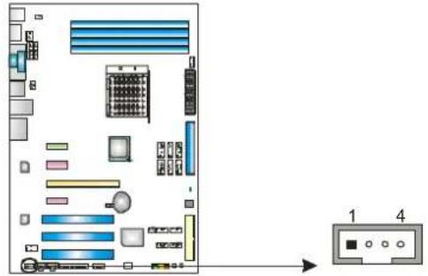
JAUDIOF1: Front Panel Audio Header
This header allows user to connect the front audio output cable with the PC front panel. This header allows only HD audio front panel connector; AC'97 connector is not acceptable.
text_image
Diagram showing internal components of a computer motherboard with an output diagram pointing to labeled ports 1 and 9.Pin Assignment
| 1 | Mic Left in | |
| 2 | Ground | |
| 3 | Mic Right in | |
| 4 | GPIO | |
| 5 | Right line in | |
| 6 | Jack | Sense |
| 7 | Front | Sense |
| 8 | Key | |
| 9 | Left line in | |
| 10 | Jack | Sense |
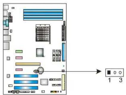
JCDIN1: CD-ROM Audio-in Connector
This connector allows user to connect the audio source from the variety devices, like CD-ROM, DVD-ROM, PCI sound card, PCI TV turner card etc.
text_image
Diagram showing internal components of a computer tower with labeled ports and connectors, including a 4-pin device.| Pin | Assignment |
| 1 | Left Channel Input |
| 2 | Ground |
| 3 | Ground |
| 4 | Right Channel Input |
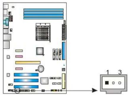
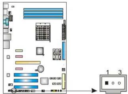
JCMOS1: Clear CMOS Header
By placing the jumper on pin2-3, it allows user to restore the BIOS safe setting and the CMOS data, please carefully follow the procedures to avoid damaging the motherboard.
text_image
Diagram of a computer motherboard with labeled components and indicator lights for ports 1 and 3
Pin 1-2 Close:
Normal Operation (default).

Pin 2-3 Close:
Clear CMOS data.
- Remove AC power line.
- Set the jumper to "Pin 2-3 close".
- Wait for five seconds.
- Set the jumper to "Pin 1-2 close".
- Power on the AC.
- Reset your desired password or clear the CMOS data.
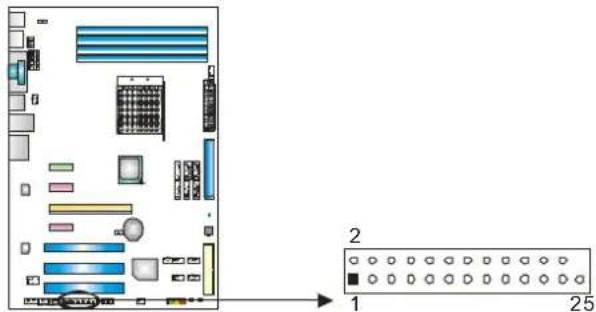
JPRNT1: Printer Port Connector
This header allows you to connector printer on the PC.
text_image
Diagram of a computer motherboard layout with labeled components and a separate 25-pin connector panel| Pin | Assignment | Pin | Assignment | ||
| 1 | -Strobe | 14 | Ground | ||
| 2 | -ALF | 15 | Data | 6 | |
| 3 | Data 0 | 16 | Ground | ||
| 4 | -Error | 17 | Data | 7 | |
| 5 | Data 1 | 18 | Ground | ||
| 6 | -Init | 19 | -ACK | ||
| 7 | Data 2 | 20 | Ground | ||
| 8 | -Scltin | 21 | Busy | ||
| 9 | Data 3 | 22 | Ground | ||
| 10 | Ground | 23 | PE | ||
| 11 | Data 4 | 24 | Ground | ||
| 12 | Ground | 25 | SCLT | ||
| 13 | Data 5 | 26 | Key | ||
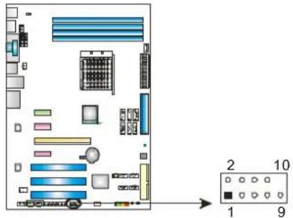
JCOM1: Serial port Connector
The motherboard has a Serial Port Connector for connecting RS-232 Port.
text_image
Diagram of a server rack with labeled ports and an output panel showing 10 ports and 9 switches.Pin Assignment
| 1 | Carrier detect |
| 2 | Received data |
| 3 | Transmitted data |
| 4 | Data terminal ready |
| 5 | Signal ground |
| 6 | Data set ready |
| 7 | Request to send |
| 8 | Clear to send |
| 9 | Ring indicator |
| 10 | NC |
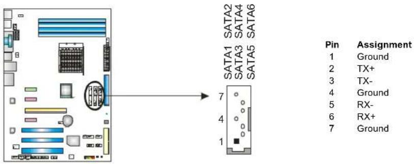
SATA1\~SATA6: Serial ATA Connectors
The motherboard has a PCI to SATA Controller with 6 channels SATA interface, it satisfies the SATA 2.0 spec and with transfer rate of 3.0Gb/s.
text_image
SATA2 SATA4 SATA6 SATA1 SATA3 SATA5 7 4 1 Pin Assignment 1 Ground 2 TX+ 3 TX- 4 Ground 5 RX- 6 RX+ 7 GroundNote:
Due to the chipset's specification, SATA5 and SATA6 do not support SATA mode, only support AHCI+RAID mode.
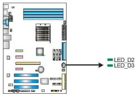
On-Board LED Indicators
There are 2 LED indicators on the motherboard to show system status. Each LED represents different system item, and lighted LED means that system item is in normal status.
text_image
LED_D2 LED_D3| LED | Status | Meaning | |
| LED_D2 | OFF | Memory Error | |
| LED_D3 | OFF | VGA Error |
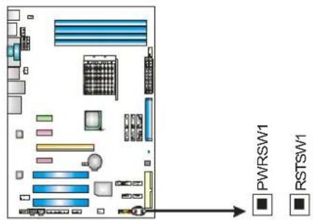
On-Board Buttons
There are 2 on-board buttons.
text_image
PWRSW1 RSTSW1PWRSW1:
This is an on-board Power Switch button.
RSTSW1:
This is an on-board Reset button.
JSPDIF\_OUT1: Digital Audio-out Connector
This connector allows user to connect the PCI bracket SPDIF output header.
text_image
Diagram of a computer system with labeled components and an output panel showing three ports labeled 1, 2, and 3.Pin Assignment
1 +5V
2 SPDIF_OUT
3 Ground
JSPDIF\_IN1: Digital Audio-in Connector
This connector allows user to connect the PCI bracket SPDIF input header.
text_image
Diagram of a computer motherboard showing labeled components and connection to an Ethernet port with ports 1 and 3 indicated.Pin Assignment
1 +5V
2 SPDIF_IN
3 Ground
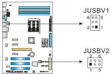
JUSBV1/JUSBV2: Power Source Headers for USB Ports
Pin 1-3 & Pin 2-4 Close:
JUSBV1: +5V for USB ports at JUSB5/JUSBLAN1.
JUSBV2: +5V for USB ports at front panel (JUSB1\~JUSB4).
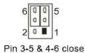
Pin 3-5 & Pin 4-6 Close:
JUSBV1: +5V STB for USB ports at JUSB5/JUSBLAN1.
JUSBV2: +5V STB for USB ports at front panel (JUSB1\~JUSB4).
text_image
JUSBV1 6 5 2 1 JUSBV2 2 6 1 5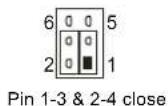
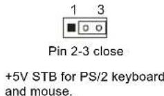
JKBV1: Power Source Header for PS/2 Keyboard and Mouse
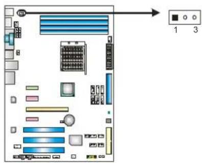
text_image
Diagram of a computer motherboard with labeled ports and indicator lights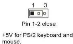
CHAPTER 4: NVIDIA RAID FUNCTIONS
Supports Windows XP and Windows VISTA.
4.2 RAID ARRAYS
NVRAID supports the following types of RAID arrays:
RAID 0: RAID 0 defines a disk striping scheme that improves disk read and write times for many applications.
RAID 1: RAID 1 defines techniques for mirroring data.
RAID 0+1: RAID 0+1 combines the techniques used in RAID 0 and RAID 1.
RAID 5: RAID 5 provides fault tolerance and better utilization of disk capacity.
4.3 How RAID WORKS
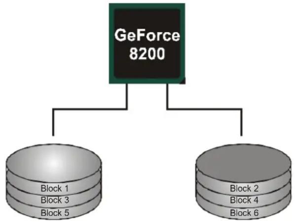
RAID 0:
The controller “stripes” data across multiple drives in a RAID 0 array system. It breaks up a large file into smaller blocks and performs disk reads and writes across multip le drives in parallel. The size of each block is determined by the stripe size parameter, which you set during the creation of the RAID set based on the system environment. This technique reduces overall disk access time and offers high bandwidth.
Features and Benefits
- Drives: Minimum 2, and maximum is up to 6 or 8. Depending on the platform.
- Uses: Intended for non-critical data requiring high data throughput, or any environment that does not require fault tolerance.
- Benefits: provides increased data throughput, especially for large files. No capacity loss penalty for parity.
- Drawbacks: Does not deliver any fault tolerance. If any drive in the array fails, all data is lost.
- Fault Tolerance: No.
flowchart
graph TD
    A["GeForce 8200"] --> B["Block 1"]
    A --> C["Block 3"]
    A --> D["Block 5"]
    A --> E["Block 2"]
    A --> F["Block 4"]
    A --> G["Block 6"]
Motherboard Manual
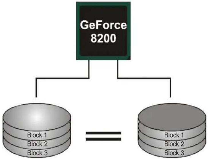
RAID 1:
Every read and write is actually carried out in parallel across 2 disk drives in a RAID 1 array system. The mirrored (backup) copy of the data can reside on the same disk or on a second redundant drive in the array. RAID 1 provides a hot-standby copy of data if the active volume or drive is corrupted or becomes unavailable because of a hardware failure. RAID techniques can be applied for high-availability solutions, or as a form of automatic backup that eliminates tedious manual backups to more expensive and less reliable media.
Features and Benefits
- Drives: Minimum 2, and maximum is 2.
- Uses: RAID 1 is ideal for small databases or any other application that requires fault tolerance and minimal capacity.
- Benefits: Provides 100% data redundancy. Should one drive fail, the controller switches to the other drive.
- Drawbacks: Requires 2 drives for the storage space of one drive. Performance is impaired during drive rebuilds.
- Fault Tolerance: Yes.
flowchart
graph TD
    A["GeForce 8200"] --> B["Block 1"]
    A --> C["Block 2"]
    A --> D["Block 3"]
    B --> E["=="]
    C --> E
    D --> E
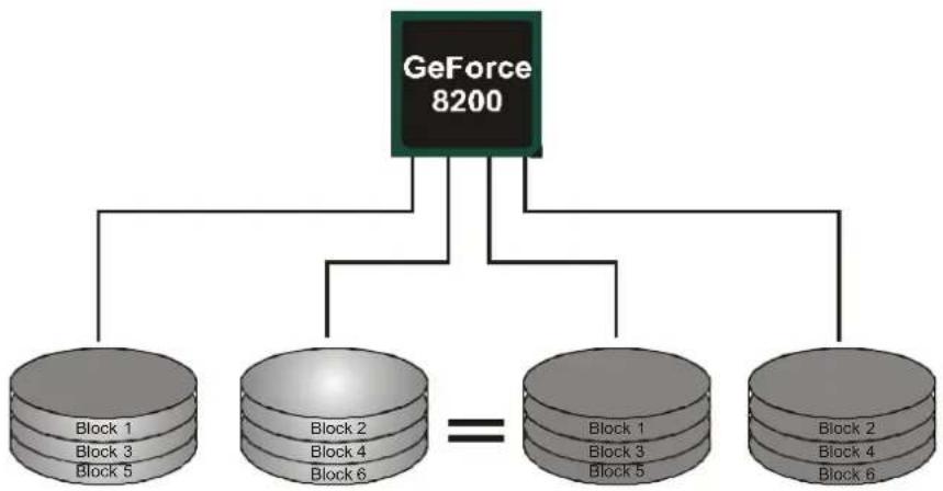
RAID 0+1:
RAID 0 drives can be mirrored using RAID 1 techniques. Resulting in a RAID 0+1 solution for improved performance plus resiliency.
Features and Benefits
- Drives: Minimum 4, and maximum is 6 or 8, depending on the platform.
- Benefits: Optimizes for both fault tolerance and performance, allowing for automatic redundancy. May be simultaneously used with other RAID levels in an array, and allows for spare disks.
- Drawbacks: Requires twice the available disk space for data redundancy, the same as RAID level 1.
- Fault Tolerance: Yes.
flowchart
graph TD
    A["GeForce 8200"] --> B["Block 1\nBlock 3\nBlock 5"]
    A --> C["Block 2\nBlock 4\nBlock 6"]
    A --> D["Block 1\nBlock 3\nBlock 5"]
    A --> E["Block 2\nBlock 4\nBlock 6"]
    B --> F["=="]
    C --> F
    D --> F
    E --> F
Motherboard Manual
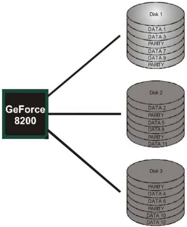
RAID 5:
RAID 5 stripes both data and parity information across three or more drives. It writes data and parity blocks across all the drives in the array. Fault tolerance is maintained by ensuring that the parity information for any given block of data is placed on a different drive from those used to store the data itself.
Features and Benefits
- Drives: Mini mum 3.
- Uses: RAID 5 is recommended for transaction processing and general purpose service.
- Benefits: An ideal combination of good performance, good fault tolerance, and high capacity and storage efficiency.
- Drawbacks: Individual block data transfer rate same as a single disk. Write performance can be CPU intensive.
- Fault Tolerance: Yes.
flowchart
graph TD
    A["GeForce 8200"] --> B["Disk 1"]
    A --> C["Disk 2"]
    A --> D["Disk 3"]
    B --> E["DATA 1"]
    B --> F["DATA 3"]
    B --> G["PARITY"]
    B --> H["DATA 7"]
    B --> I["DATA 9"]
    B --> J["PARITY"]
    C --> K["DATA 2"]
    C --> L["PARITY"]
    C --> M["DATA 5"]
    C --> N["DATA 8"]
    C --> O["PARITY"]
    C --> P["DATA 11"]
    D --> Q["PARITY"]
    D --> R["DATA 4"]
    D --> S["DATA 6"]
    D --> T["PARITY"]
    D --> U["DATA 10"]
    D --> V["DATA 12"]
※ For more detailed setup information, please refer to the Driver CD, or go to http://www.nvidia.com/object/IO_28159.html to download the NVIDIA RAID User's Guide.
CHAPTER 5: T-SERIES BIOS & SOFTWARE
5.1 T-SERIES BIOS
T-Series BIOS Features
Overclocking Navigator Engine (O.N.E.)
■ Memory Integration Test (M.I.T., under Overclock Navigator Engine)
BIO-Flasher: Update BIOS file from USB Flash Drive or FDD
■ Self Recovery System (S.R.S)
Smart Fan Function
CMOS Reloading Program
!! WARNING !!
For better system performance, the BIOS firmware is being continuously updated. The BIOS information described below in this manual is for your reference only and the actual BIOS information and settings on board may be different from this manual. For further information of setting up the BIOS, please refer to the BIOS Manual in the Sectu CD.
A. Overclocking Navigator Engine (O.N.E.)
ONE provides two powerful overclocking engines: MOS and AOS for both Elite and Casual overclockers.
| Main Advanced PCIPnP Boot Chipset Series Exit | ||
| T-Series Settings | Options Normal Automate OverClock Manual OverClock | |
| WARNING: Setting wrong values in below sections may cause system to malfunction. | ||
| OverClock Navigator [Normal] | ||
| -Automate OverClock System - | ||
| Auto OverClock System [V6-Tech Engine] | ||
| - Manual OverClock System - | ||
| > Over-Voltage Configuration | ||
| > DRAM Timing Configuration | ||
| > Spread Spectrum Configuration | ||
| CPU Frequency, MHz [200] | ||
| Processor Frequency Multiplier [Auto] | ||
| SB to K8(CPU) Freq Auto [Enabled] | ||
| SB to K8(CPU) LinkWidth [16 16 ] | ||
| Memory Clock Mode [Auto] | ||
| MCP PCI-Express Frequency, MM [100] | ||
| Integrated Memory Test [Disabled] | ||
| vxx.xx (C) Copyright 1985-200x, American Megatrends, Inc. | ||
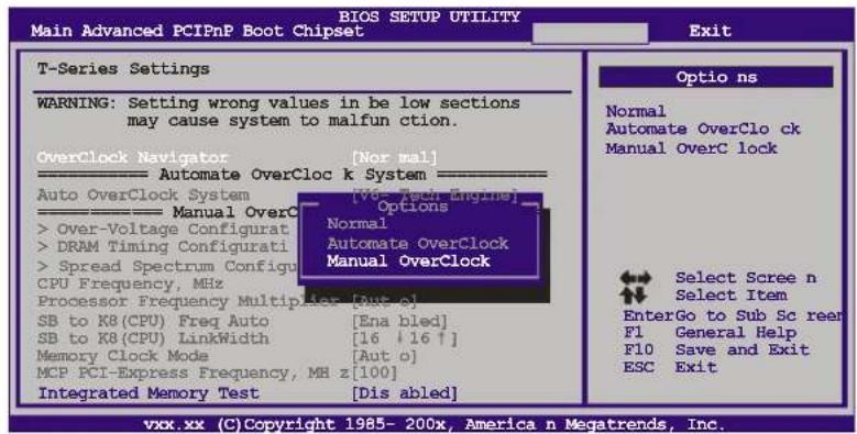
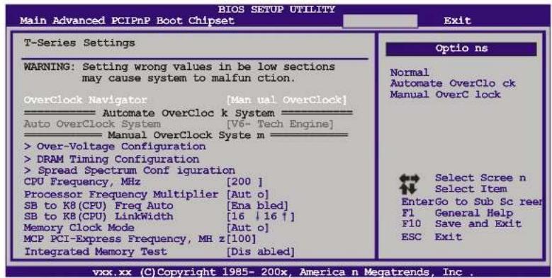
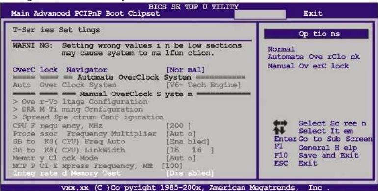
Manual Overclock System (M.O.S.)
MOS is designed for experienced overclock users.
It allows users to customize personal overclock settings.
text_image
Main Advanced PCIPnP Boot Chipset BIOS SETUP UTILITY Main Advanced PCIPnP Boot Chipset Exit T-Series Settings WARNING: Setting wrong values in be low sections may cause system to malfunction. OverClock Navigator [Nor mal] Automate OverCloc k System Auto OverClock System [Vdc Tech Engine] Manual OverC > Over-Voltage Configurat > DRAM Timing Configurati > Spread Spectrum Configu CPU Frequency, MHz Processor Frequency Multiplier [Out o] SB to K8 (CPU) Freq Auto [Ena bled] SB to K8 (CPU) LinkWidth [16 +16 +] Memory Clock Mode [Aut o] MCP PCI-Express Frequency, MH z [100] Integrated Memory Test [Dis abled] Optio ns Normal Automate OverClo ck Manual OverC lock Select Scree n Select Item EnterGo to Sub Sc rear F1 General Help F10 Save and Exit ESC Exit vxx.xx (C) Copyright 1985- 200x, America n Megatrends, Inc.↓
text_image
BIOS SETUP UTILITY Main Advanced PCIPnP Boot Chipset Exit T-Series Settings WARNING: Setting wrong values in be low sections may cause system to malfunction. OverClock Navigator [Manual OverClock] Automate OverCloc k System Auto OverClock System [V6- Tech Engine] Manual OverClock Syste m > Over-Voltage Configuration > DRAM Timing Configuration > Spread Spectrum Conf iguration CPU Frequency, MHz [200 ] Processor Frequency Multiplier [Aut o] SB to K8 (CPU) Freq Auto [Ena bled] SB to K8 (CPU) LinkWidth [16 ↓ 16 ↑] Memory Clock Mode [Aut o] MCP PCI-Express Frequency, MH z [100] Integrated Memory Test [Dis abled] Optio ns Normal Automate OverClo ck Manual OverC lock Select Scree n Select Item EnterGo to Sub Sc reer F1 General Help F10 Save and Exit ESC Exit vxx.xx (C) Copyright 1985- 200x, America n Megatrends, Inc.Over-Voltage Configuration
Enter this function for advanced CPU/chipset/memory/Hyper Transport over-voltage settings.
DRAM Timing Configuration
Enter this function for more advanced DRAM clock settings.
Spread Spectrum Configuration
Enter this function for more advanced spread spectrum settings.
CPU Frequency, MHz
CPU Frequency is directly in proportion to system performance. To maintain the system stability, CPU voltage needs to be increased also when raising CPU frequency.
Processor Frequency Multiplier
This function allows you to adjust the frequency ratio of CPU.
SB to K8(CPU) Freq Auto
This function allows you to set the SB to K8 frequency.
SB to K8(CPU) LinkWidth
This function allows you to choose the SB to K8 link width.
Memory Clock Mode
This function allows you to control the Memory Clock.
MCP PCI-Express Frequency, MHz
It helps to increase VGA card performance.
NOTE
Overclock is an optional process, but not a “must-do” process; it is not recommended for inexperienced users. Therefore, we will not be responsible for any hardware damage which may be caused by overclocking. We also would not guarantee any overclocking performance.
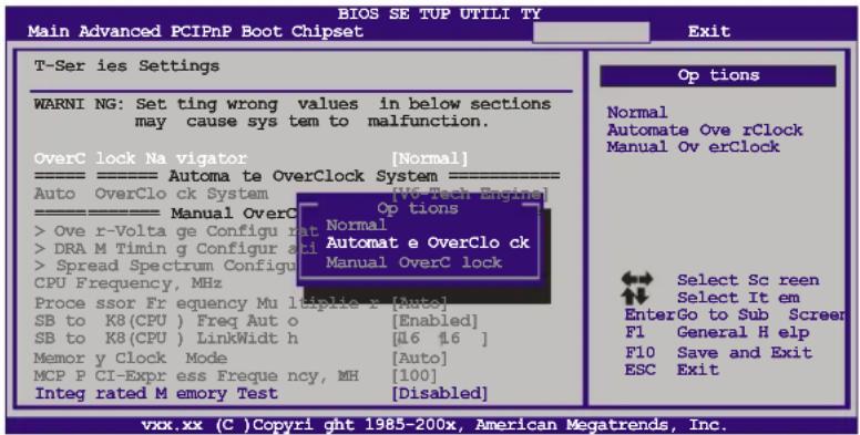
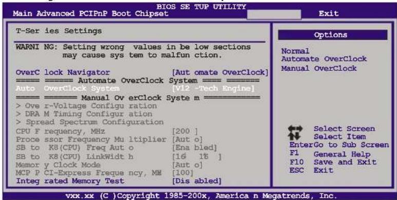
Automatic Overclock System (A.O.S.)
For beginners in overclock field, BET had developed an easy, fast, and powerful feature to increase the system performance, named A.O.S. Based on many tests and experiments, A.O.S. provides 3 ideal overclock configurations that are able to raise the system performance in a single step.
text_image
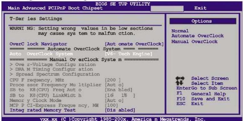
BIOS SE TUP UTILI TY Main Advanced PCIPnP Boot Chipset Exit T-Ser ies Settings WARNl NG: Set ting wrong values in below sections may cause sys tem to malfunction. OverC lock Na vigator [Normal] -------- Automa te OverClock System Auto OverClo ck System [V6 Tech Engine] -------- Manual OverC > Ove r-Volta ge Configu rat Normal > DRA M Timin g Configur ati Automat e OverClo ck > Spread Spectrum Configu CPU Frequency, MHz Manual OverC lock Proce ssor Fr equency Mu leplie x [Auto] SB to K8(CPU) Freq Auto [Enabled] SB to K8(CPU) LinkWidt h [16 16 ] Memor y Clock Mode [Auto] MCP P CI-Express Frequncy, MH [100] Integ rated M emory Test [Disabled] Options Normal Automate Ove rClock Manual Ov erClock Select Sc reen Select It em EnterGo to Sub Screer F1 General H elp F10 Save and Exit ESC Exit vxx.xx (C) Copyright 1985-200x, American Megatrends, Inc.V6 Tech Engine
This engine will make a good over-clock performance.
text_image
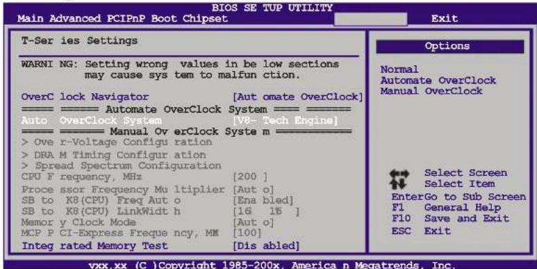
BIOS SE TUP UTILITY Main Advanced PCIPnP Boot Chipset Exit T-Ser ies Settings WARNl NG: Setting wrong values in be low sections may cause sys tem to malfun ction. OverC lock Navigator [Aut omate OverClock] Automate OverClock System Auto OverClock System [V6- Tech Engine] Manual Ov erClock Syste m Ove r-Voltage Configu ration DRA M Timing Configur ation Spread Spectrum Configuration CPU F frequency, MHz [200 ] Proce ssor Frequency Mu ltiplier [Aut o] SB to K8(CPU) Freq Aut o [Ena bled] SB to K8(CPU) LinkWidt h [16 16 ] Memor y Clock Mode [Aut o] MCP P CI-Express Frequ ency, MM [100] Integ rated Memory Test [Dis abled] Options Normal Automate OverClock Manual OverClock Select Screen Select Item EnterGo to Sub Screen F1 General Help F10 Save and Exit ESC Exit vxx.xx (C) Copyright 1985-200x, America n Megatrends, Inc.V8 Tech Engine
This engine will make a better over-clock performance.
text_image
BIOS SE TUP UTILITY Main Advanced PCIPnP Boot Chipset Exit T-Ser ies Settings WARNl NG: Setting wrong values in be low sections may cause sys tem to malfun ction. OverC lock Navigator [Aut omate OverClock] Automate OverClock System Auto OverClock System [V8- Tech Engine] Manual OverClock Syste m >Ove r-Voltage Configu ration >DRA M Timing Configur ation >Spread Spectrum Configuration CPU F frequency, MHz [200 ] Proce ssor Frequency Mu ltiplier [Aut o] SB to K8(CPU) Freq Aut o [Ena bled] SB to K8(CPU) LinkWidt h [16 15 ] Memor y Clock Mode [Aut o] MCP F CI-Express Freque ncy, MM [100] Integ rated Memory Test [Dis abled] Options Normal Automate OverClock Manual OverClock Select Screen Select Item EnterGo to Sub Screen F1 General Help F10 Save and Exit ESC Exit vix.xx (C )Copyright 1985-200x, America n Megatrends, Inc.V12 Tech Engine
This engine will make a best over-clock performance.
text_image
BIOS SE TUP UTILITY Main Advanced PCIPnP Boot Chipset Exit T-Ser ies Settings WARNl NG: Setting wrong values in be low sections may cause sys tem to malfun ction. OverC lock Navigator [Aut omate OverClock] Auto Automate OverClock System [V12 -Tech Engine] Manual Ov erClock Syste m > Ove r-Voltage Configu ration >DRA M Timing Configu ation > Spread Spectrum Configuration CPU F frequency, MHz [200 ] Proce ssor Frequency Mu ltiplier [Aut o] SB to K8(CPU) Freq Aut o [Ena bled] SB to K8(CPU) LinkWidt h [16 18 ] Memor y Clock Mode [Aut o] MCP P CI-Express Freque ncy, MM [100] Integ rated Memory Test [Dis abled] Options Normal Automate OverClock Manual OverClock Select Screen Select Item EnterGo to Sub Screen F1 General Help F10 Save and Exit ESC Exit vxx.xx (C) Copyright 1985-200x, America n Megatrends, Inc.Notices:
- Not all types of AMD CPU perform above overclock setting ideally; the difference will be based on the selected CPU model.
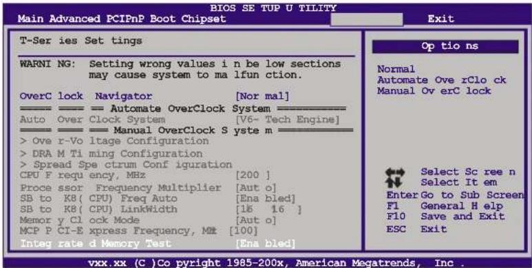
B. Memory Integration Test (M.I.T.)
This function is under "Overclocking Navigator Engine" item.
MIT allows users to test memory compatibilities, and no extra devices or software are needed.
Step 1
The default setting under this item is "Disabled"; the condition parameter should be changed to "Enable" to proceed this test.
text_image
BIOS SE TUP U TILITY Main Advanced PCIPnP Boot Chipset Exit T-Ser ies Set tings WARNl NG: Setting wrong values i n be low sections may cause system to ma lfun ction. OverC lock Navigator [Nor mal] Auto Over Clock System [V6- Tech Engine] Manual OverClock S yste m > Ove r-Vo ltage Configuration >DRA M Ti ming Configuration > Spread Spe ctrum Conf iguration CPU F requ ency, MHz [200 ] Proce ssor Frequency Multiplier [Aut o] SB to K8( CPU) Freq Auto [Ena bled] SB to K8( CPU) LinkWidth [16 16 ] Memor y Cl ock Mode [Aut o] MCP P CI-E xpress Frequency, MT [100] Integ rate d Memory Test [Dis abled] Op tio ns Normal Automate Ove rClo ck Manual Ov erC lock Select Sc ree n Select It em Enter Go to Sub Screen F1 General H elp F10 Save and Exit ESC Exit vxx.xx (C )Co pyright 1985-200x, American Megatrends, Inc.↓
text_image
BIOS SE TUP U TILITY Main Advanced PCIPnP Boot Chipset Exit T-Ser ies Set tings WARN! NG: Setting wrong values i n be low sections may cause system to ma lfun ction. OverC lock Navigator [Nor mal] —— —— —— Automate OverClock System ——— Auto Over Clock System [V6- Tech Engine] —— ——— Manual OverClock S yste m ——— > Ove r-Vo ltage Configuration > DRA M Ti ming Configuration > Spread Spe ctrum Conf iguration CPU F requ ency, MHz [200 ] Proce ssor Frequency Multiplier [Aut o] SB to K8( CPU) Freq Auto [Ena bled] SB to K8( CPU) LinkWidth [15 16 ] Memor y Cl ock Mode [Aut o] MCP P CI-E xpress Frequency, Mt [100] Integ rate d Memory Test [Ena bled] Op tio ns Normal Automate Ove rClo ck Manual Ov erC lock Select Sc ree n Select It em Enter Go to Sub Screen F1 General H elp F10 Save and Exit ESC Exit vxx.xx (C )Co pyright 1985-200x, American Megatrends, Inc.Step 2
Save and Exit from CMOS setup and reboot the system to activate this test.
Run this test for 5 minutes (minimum) to ensure the memory stability.
Step 3
When the process is done, change the setting back from "Enable" to "Disable" to complete the test.
©
D. Self Recovery System (S.R.S.)
This function can't be seen under BIOS setup; and is always on whenever the system starts up.
However, it can prevent system hang-up due to inappropriate overclock actions.
When the system hangs up, S.R.S. will automatically log in the default BIOS setting, and all overclock settings will be re-configured.
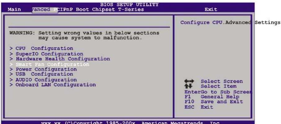
E. Smart Fan Function
Smart Fan Function is under "Smart Fan Configuration" in "Advanced Menu". This is a brilliant feature to control CPU/System Temperature vs. Fan speed. When enabling Smart Fan function, Fan speed is controlled automatically by CPU/System temperature.
This function will protect CPU/System from overheat problem and maintain the system temperature at a safe level.
text_image
BIOS SETUP UTILITY Main 7anced PCIPnP Boot Chipset T-Series Exit WARNING: Setting wrong values in below sections may cause system to malfunction. > CPU Configuration > SuperIO Configuration > Hardware Health Configuration > Smart Fan Configuration > Power Configuration > USB Configuration > AUDIO Configuration > Onboard LAN Configuration Configure CPU.Advanced Settings Select Screen Select Item EnterGo to Sub Screen F1 General Help F10 Save and Exit ESC Exit vxx.xx (C)Copyright 1985-200x, American Megatrends, Inc.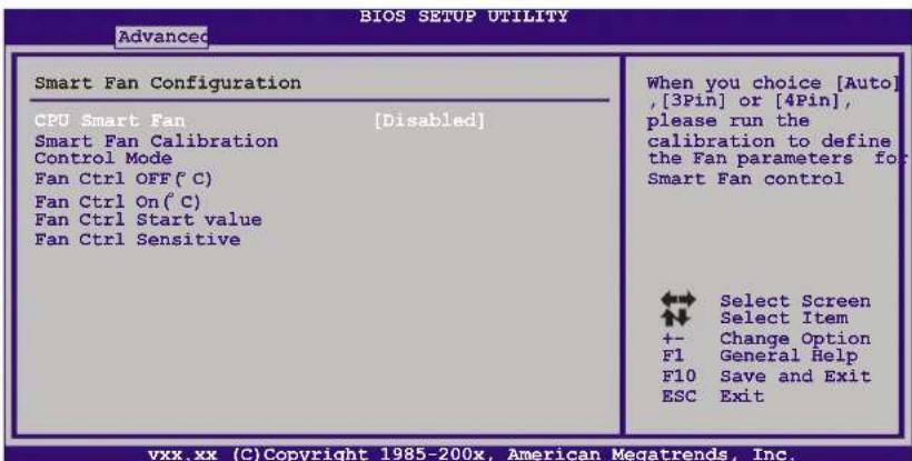
text_image
ADVANCED BIOS SETUP UTILITY Smart Fan Configuration CPU Smart Fan [Disabled] Smart Fan Calibration Control Mode Fan Ctrl OFF(°C) Fan Ctrl On(°C) Fan Ctrl Start value Fan Ctrl Sensitive When you choice [Auto], [3Pin] or [4Pin], please run the calibration to define the Fan parameters for: Smart Fan control Select Screen Select Item +- Change Option F1 General Help F10 Save and Exit ESC Exit vxx.xx (C)Copyright 1985-200x, American Megatrends, Inc.Motherboard Manual
Smart Fan Calibration
Choose this item and then the BIOS will automatically test and detect the CPU/System fan functions and show CPU/System fan speed.
Control Mode
This item provides several operation modes of the fan.
Fan Ctrl OFF(°C)
If the CPU/System temperature is lower than the set value, the CPU/System fan will turn off. The range is from 0\~127, with an interval of 1.
Fan Ctrl On(℃)
The CPU/System fan starts to work when CPU/System temperature arrives to this set value. The range is from 0\~127, with an interval of 1.
Fan Ctrl Start Value
When CPU/System temperature arrives to the set value, the CPU/System fan will work under Smart Fan Function mode. The range is from 0\~127, with an interval of 1.
Fan Ctrl Sensitive
Increasing the value of slope PWM will raise the speed of CPU/System fan. The range is from 1\~127, with an interval of 1.
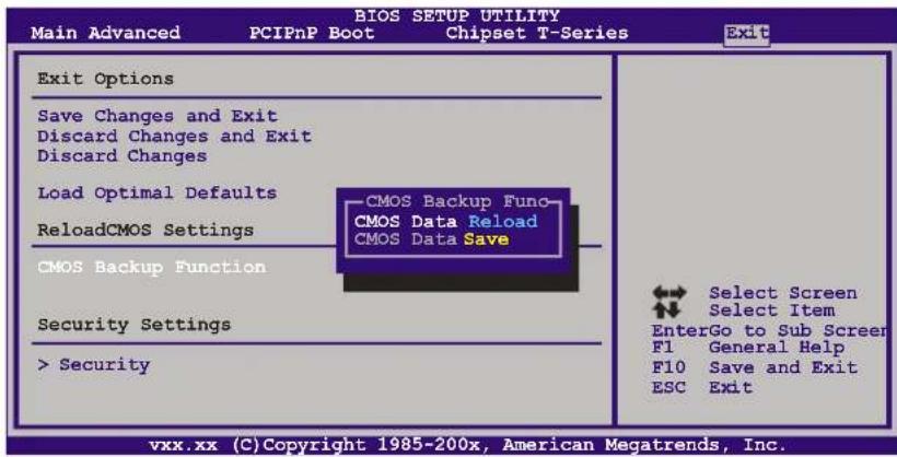
F. CMOS Reloading Program
It allows users to save different CMOS settings into BIOS-ROM.
Users are able to reload any saved CMOS setting for customizing system configurations. Moreover, users are able to save an ideal overclock setting during overclock operation.
There are 10 sets of record addresses in total, and users are able to name the CMOS data according to personal preference.
text_image
Main Advanced PCIPnP Boot Chipset T-Series Exit BIOS SETUP UTILITY Exit Options Save Changes and Exit Discard Changes and Exit Discard Changes Load Optimal Defaults ReloadCMOS Settings CMOS Backup Function Security Settings > Security CMOS Backup Func CMOS Data Reload CMOS Data Save Select Screen Select Item EnterGo to Sub Screer F1 General Help F10 Save and Exit ESC Exit vxx.xx (C) Copyright 1985-200x, American Megatrends, Inc.5.2 T-SERIES SOFTWARE
Installing T-Series Software
- Insert the Setup CD to the optical drive. The drivers installation program would appear if the Auto-run function has been enabled.
- Select Software Installation, and then click on the respective software title.
- Follow the on-screen instructions to complete the installation.
Launching T-Series Software
After the installation process, you will see the software icon "T-Utility OverClock III" / "HW Monitor" / "eHOT Line" / "Tseries BIOS Update" appears on the desktop. Double-click the icon to launch T-Series utility.
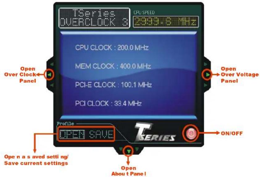
OverClock 3
OverClock 3 is equipped with friendly interface and solid over-clock features, and it will help you easily do over-clocking under windows environment.
Double-click the desktop icon, OverClock 3 will be launched; the first window you will see is Main Panel. In this panel you will see current CPU Speed and CPU/Memory/PCI-E/PCI Clock.
text_image
TSeries OVERCLOCK 3 CPU SPEED 2009.6 MHz CPU CLOCK : 200.0 MHz MEM CLOCK : 400.0 MHz PCI-E CLOCK : 100.1 MHz PCI CLOCK : 33.4 MHz Open Over Clock Panel Open Over Voltage Panel Profile OPEN SAVE T SERIES Open n a s saved setti ng/ Save current settings Open About t PanelOver Clock Panel
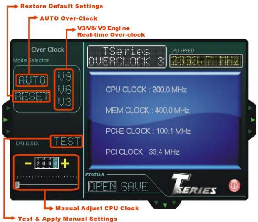
text_image
Restore Default Settings AUTO Over-Clock V3/V6/ V9 Engi ne Real-time Over-clock Over Clock Mode Selection: AUTO V9 RESET V8 CPU CLOCK: TEST - 2 0 0 + Manual Adjust CPU Clock Test & Apply Manual Settings TSeries OVERCLOCK 3 CPU SPEED 2000.7 MHz CPU CLOCK : 200.0 MHz MEM CLOCK : 400.0 MHz PCI-E CLOCK : 100.1 MHz PCI CLOCK : 33.4 MHz Profile OPEN SAVE T SERIESAUTO
User can click this button and the utility will set the best and stable performance and frequency automatically. A warning dialog as below will show up to notify you that the system may become unstable, click on "OK" to continue.
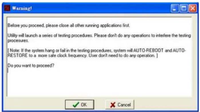
text_image
Before you proceed, please close all other running applications first. Utility will launch a series of testing procedures. Please don't do any operations to interfere the testing procedures. [ Note: If the system hang or fail in the testing procedures, system will AUTO-REBOOT and AUTO- RESTORE to a more safe clock frequency. User don't need to do any operation. ] Do you want to proceed? OK CancelThen the utility will execute a series of testing until system fail. Then system will do fail-safe reboot by using Watchdog function. After reboot, launch the utility again and the utility will load the previously verified best and stable frequency.
V3 / V6 / V9
Provide user the ability to do real-time over-clock adjustment. For beginners in over-clock field, this is a powerful feature to increase system performance.
■ V3 Engine
This engine will make a good over-clock performance.
■ V6 Engine
This engine will make a better over-clock performance.
■ V9 Engine
This engine will make a best over-clock performance.
TEST
You can also manually adjust CPU clock by pressing +/- button or moving the level bar. After manually adjust the CPU clock, you should click TEST button and the utility will proceed a testing for current frequency. If the testing is ok, then the current frequency will be saved into system registry. If the testing fails, system will do a fail-safe rebooting. After reboot, the utility will restore to the hardware default setting.
Warning
Manually over-clock is potentially dangerous, especially when the over-clocking percentage is over 110 %. We strongly recommend you test every speed you over-clock by click the TEST button. Or, you can just click AUTO over-clock button and let the Utility automatically get the best result for you.
RESET
Click this button and the utility will restore all values to the hardware default setting.
Over Voltage Panel
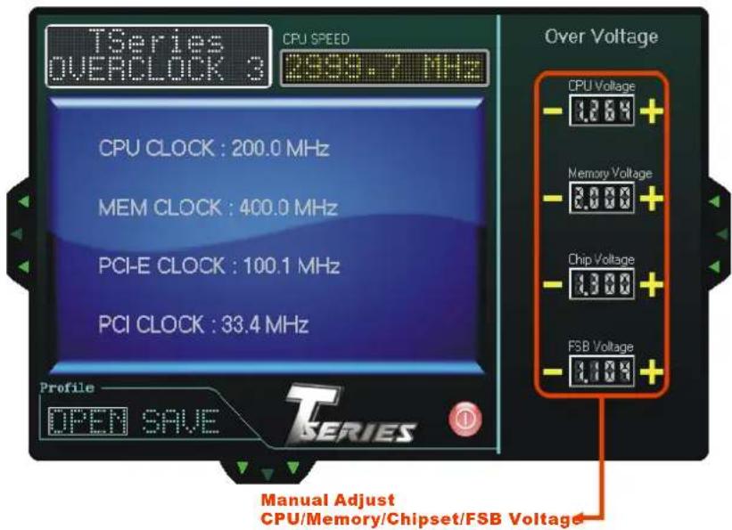
text_image
TSeries OVERCLOCK 3 CPU SPEED 2999.7 MHz CPU CLOCK : 200.0 MHz MEM CLOCK : 400.0 MHz PCI-E CLOCK : 100.1 MHz PCI CLOCK : 33.4 MHz Profile OPEN SAVE Over Voltage CPU Voltage -1.264+ Memory Voltage -2.000+ Chip Voltage -1.300+ FSB Voltage -1.104+ Manual Adjust CPU/Memory/Chipset/FSB VoltageCPU Voltage
This function allows user to adjust CPU voltage. Click on “+” to increase or “-” to decrease the CPU voltage.
Memory Voltage
This function allows user to adjust Memory voltage. Click on "+" to increase or "-" to decrease the Memory voltage.
Chip Voltage
This function allows user to adjust Chipset voltage. Click on "+" to increase or "-" to decrease the Chipset voltage.
FSB Voltage
This function allows user to adjust FSB voltage. Click on “+” to increase or “-” to decrease the FSB voltage.
About Panel
In this panel, you can get model name and other system information that may related to over-clocking. You can also get the version number of this software.
Note
Because the Over Clock and Over Voltage features are controlled by several separate chipset, the utility divides these features to separate panels. If one chipset is not on board, the correlative button in Main panel will be disabled, but it will not interfere with other panels' functions. This property can make the utility more robust.
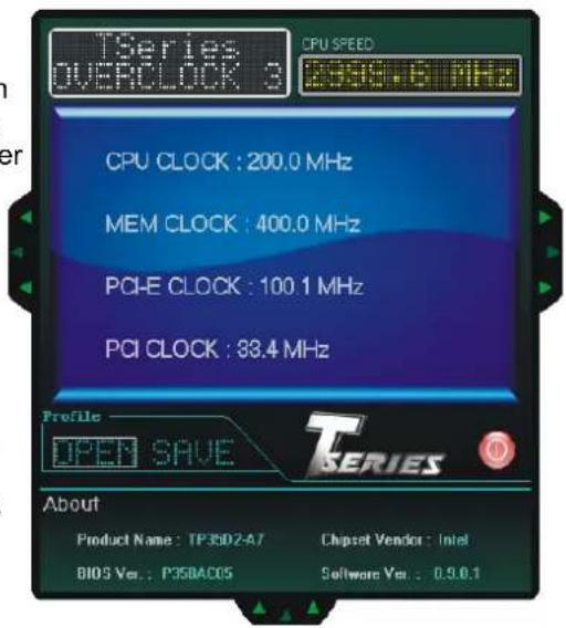
text_image
TSeries OVERCLOCK 3 CPU SPEED 200.0 MHz CPU CLOCK : 200.0 MHz MEM CLOCK : 400.0 MHz PCI-E CLOCK : 100.1 MHz PCI CLOCK : 88.4 MHz Profile OPEN SAVE T SERIES About Product Name : TP36D2-A7 Chipset Vendor : Intel BIOS Ver. : P35BAC05 Software Ver. : 0.9.0.1Hardware Monitor
HW Monitor is a monitor utility that helps you to maintain the health of the PC. It provides real-time information of CPU/GPU/System temperature, fan speed, and voltage.
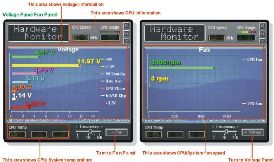
text_image
Thi s area shows voltage i n formati on Voltage Panel Fan Panel Thi s area shows CPU inf or mation Hardware Monitor CPU Speed CPU Usage MHz Voltage 4.97 V 11.97 V +5V +12V -5V Standby -Balt Volt. -CPU VCore -NB/SB Chip +3.3V 0 2 4 6 8 10 12 14 Light button on panel /r popus menu >> < Turn to move mouse cursor on any ke Hardware Monitor CPU Speed CPU Usage MHz Fan 5000 rpm 0 rpm SYS Fan Turn to Fan Panel CPU Temp < Transpency > > Fan 0 50 100 0 50 100 0 50 100 < Turn to Voltage Panel CPU/System temp erat ure Thi s area shows CPU/System tem fan speed Turn to Voltage PaneleHot-Line (Optional)
eHot-Line is a convenient utility that helps you to contact with our Tech-Support system. This utility will collect the system information which is useful for analyzing the problem you may have encountered, and then send these information to our tech-support department to help you fix the problem.

Before you use this utility, please set Outlook Express as your default e-mail client application program.
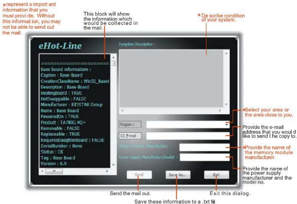
text_image
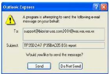
eHot-Line Base board information : Caption : Base Board CreationClassName : Win32_Basel Description : Base Board HostingBoard : TRUE HotSwappable : FALSE Manufacturer : BIDSTAR Group Name : Base Board PoweredOn : TRUE Product : TA780G M2+ Removable : FALSE Replaceable : TRUE RequiresDaughterBoard : FALSE SerialNumber : None Status : OK Tag : Base Board Version : 6.0 Symptom Description : Region : CC E-mail : Power Supply/Manufacture: Power Supply/Manufacture/model : Send Save As... Exit *represent s import ant information that you must provi de. Without this informat ion, you may not be able to send out the mail. *De scribe condition of your system. *Select your area or the area close to you. Provide the e-mail address that you would like to send t he copy to. *Provide the name of the memory module manufacturer. Provide the name of the power supply manufacturer and the model no. Send the mail out. Save these information to a .txt fil Exit this dialog.After filling up this information, click "Send" to send the mail out. A warning dialog would appear asking for your confirmation; click "Send" to confirm or "Do Not Send" to cancel.
text_image
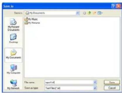
Outlook Express A program is attempting to send the following e-mail message on your behalf: To: support@biostar.usc.com/XX-XX-XX-XX-XX- Subject: TP35D2A7 (P35DAC05 BSI) report Would you like to send the message? Send Do Not SendIf you want to save this information to a .txt file, click "Save As..." and then you will see a saving dialog appears asking you to enter file name.
Enter the file name and then click "Save". Your system information will be saved to a .txt file.
text_image
Save As My Documents My Music My Pictures My Recent Documents Desktop My Documents My Computer My Network File name: report.txt Save on table: Text Files(*.txt) Cancel
text_image
file Edit View Help File Edit View Help Name: Date: 01/02/2015 Description: Name: Product: Product name: Product type: Product name: Product type: Product type: Product type: Product type: Product type: Product type: Product type: Product type: Product type: Product type: Product type: Product type: Product type: Product type: Product type: Product type: Product type: Product type: Product type: Product type: Product type: Product type: Product type: Product type: Product type: Product Type: Product Type: Product Type: Product Type: Product Type: Product Type: Product Type: Product Type: Product Type: Product Type: Product Type: Product Type: Product Type: Product Type: Product Type: Product Type: Product Type: Product Type: Product Type: Product Type: Product Type: Product Type: Product Type: Product Type: Product Type: ProductType ProductType ProductType ProductType ProductType ProductType ProductType ProductType ProductType ProductType ProductType ProductType ProductType ProductType ProductType ProductType ProductType ProductType ProductType ProductType ProductType ProductType ProductType ProductType ProductType ProductType ProductType ProductType ProductType ProductType ProductType ProductType ProductType ProductType Customer Customer Customer Customer Customer Customer Customer Customer Customer Customer Customer Customer Customer Customer Customer Customer Customer Customer Customer Customer Customer Customer Customer Customer Customer Customer Customer Customer Customer Customer Customer Customer Customer Customer Customer Customer Customer Customer Customer Customer Customer Customer Customer Customer Customer Customer Customer Customer Customer Customer Circuit1.0000000000000000000000000000000000000000000000000000000000000000000000000000000000000000000000000000Open the saved .txt file, you will see your system information including motherboard/BIOS/CPU/video/device/OS information. This information is also concluded in the sent mail.

We will not share customer's data with any other third parties, so please feel free to provide your system information while using eHot-Line service.

If you are not using Outlook Express as your default e-mail client application, you may need to save the system information to a .txt file and send the file to our tech support with other e-mail application. Go to the following web http://www.biostar.com.tw/app/en-us/about/contact.php for getting our contact information.
BIOS Update
BIOS Update is a convenient utility which allows you to update your motherboard BIOS under Windows system.
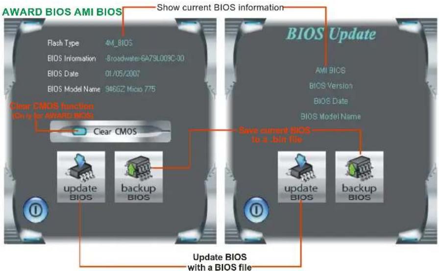
text_image
AWARD BIOS AMI BIOS Show current BIOS information Flash Type 4M_BIOS BIOS Information -Broadwater-6A79L003C-00 BIOS Date 01/05/2007 BIOS Model Name 846GZ Micio 775 Clear CMOS function On by for AWARD BIOS Clear CMOS BIOS Update AMI BIOS BIOS Version BIOS Date BIOS Model Name update BIOS backup BIOS save current BIOS to a .bin file update BIOS backup BIOS Update BIOS with a BIOS fileOnce click on this button, the saving dialog will show. Choose the position to save file and enter file name. (We recommend that the file name should be English/number and no longer than 7 characters.) Then click Save.
text_image
Bios Save BIOS Finish ! OK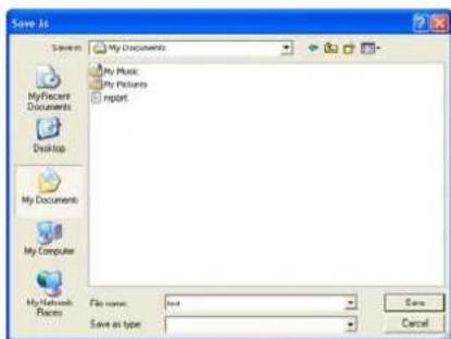
text_image
Save As My Documents My Music My Pictures Report My Recent Documents Desktop My Documents My Computer My Network Places File name: text Save as type Save As type CancelAfter the saving process, finish dialog will show. Click on OK to complete the BIOS Backup procedure.
Before doing this, please download the proper BIOS file from the website.
For AWARD BIOS, update BIOS procedure should be run with Clear CMOS function, so please check on Clear CMOS first.
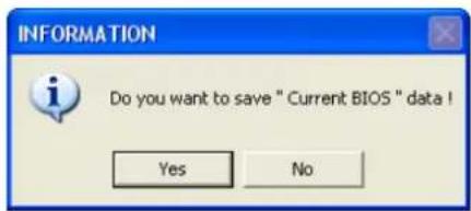
text_image
INFORMATION Do you want to save " Current BIOS " data ! Yes NoThen click Update BIOS button, a dialog will show for asking you backup current BIOS. Click Yes for BIOS backup and refer to the Backup BIOS procedure; or click No to skip this procedure.
After the BIOS Backup procedure, the open dialog will show for requesting the BIOS file which is going to be updated. Please choose the proper BIOS file for updating, then click on Open.
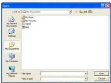
text_image
Open My Documents My Maps My Pictures Import Text My Documents My Computer My Network Files File name: File of type: Open Cancel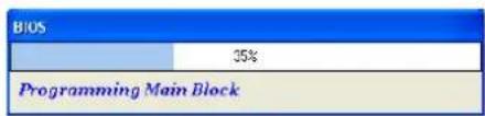
bar_stacked
| Category | Value (%) | |---|---| | BIOS | 35 | | Programming Main Block | 10 |The utility will update BIOS with the proper BIOS file, and this process may take minutes. Please do not open any other applications during this process.
After the BIOS Update process, click on OK to restart the system.
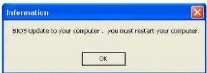
text_image
Information BIOS Update to your computer, you must restart your computer. OKWhile the system boots up and the full screen logo shows, press
In the BIOS setup, use the Load Optimized Defaults function and then Save and Exit Setup to exit BIOS setup. BIOS Update is completed.

All the information and content above about the T-Series software are subject to be changed without notice. For better performance, the software is being continuously updated. The information and pictures described above are for your reference only. The actual information and settings on board may be slightly different from this manual.
CHAPTER 6: USEFUL HELP
6.1 DRIVER INSTALLATION NOTE
After you installed your operating system, please insert the Fully Setup Driver CD into your optical drive and install the driver for better system performance.
You will see the following window after you insert the CD
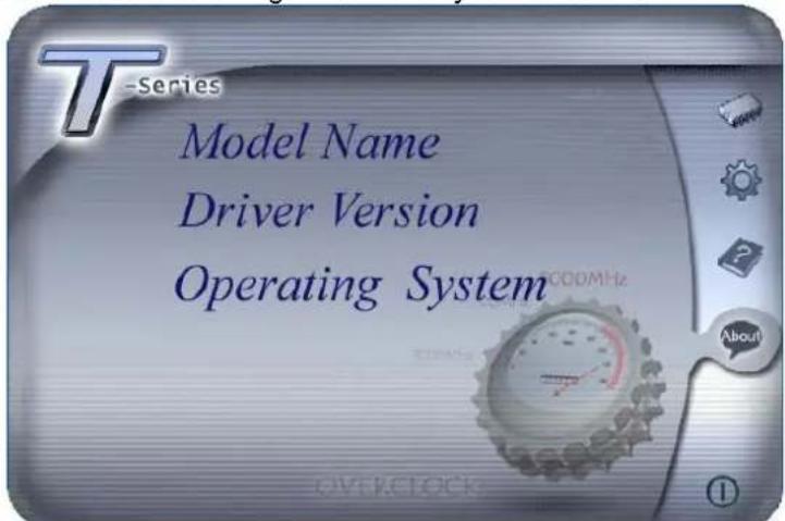
text_image
T-Series Model Name Driver Version Operating SystemThe setup guide will auto detect your motherboard and operating system.
Note:
If this window didn't show up after you insert the Driver CD, please use file browser to locate and execute the file SETUP.EXE under your optical drive.
A. Driver Installation
To install the driver, please click on the Driver icon. The setup guide will list the compatible driver for your motherboard and operating system. Click on each device driver to launch the installation program.
B. Software Installation
To install the software, please click on the Software icon. The setup guide will list the software available for your system, click on each software title to launch the installation program.
C. Manual
Aside from the paperback manual, we also provide manual in the Driver CD. Click on the Manual icon to browse for available manual.
Note:
You will need Acrobat Reader to open the manual file. Please download the latest version of Acrobat Reader software from http://www.adobe.com/products/acrobat/readstep2.html
6.2 EXTRA INFORMATION
CPU Overheated
If the system shutdown automatically after power on system for seconds, that means the CPU protection function has been activated.
When the CPU is over heated, the motherboard will shutdown automatically to avoid a damage of the CPU, and the system may not power on again.
In this case, please double check:
- The CPU cooler surface is placed evenly with the CPU surface.
- CPU fan is rotated normally.
- CPU fan speed is fulfilling with the CPU speed.
After confirmed, please follow steps below to relief the CPU protection function.
- Remove the power cord from power supply for seconds.
- Wait for seconds.
- Plug in the power cord and boot up the system.
Or you can:
- Clear the CMOS data.
(See "Close CMOS Header: JCMOS1" section) - Wait for seconds.
- Power on the system again.
6.3 AMI BIOS BEEP CODE
Boot Block Beep Codes
| Number of Beeps | Description |
| 1 No media present. (Insert diskette in floppy drive A:) | |
| 2 | “AMIBOOT.ROM” file not found in root directory of diskette in A: |
| 3 Insert next diskette if multiple diskettes are used for recovery | |
| 4 Flash Programming successful | |
| 5 File read error | |
| 7 No Flash EPROM detected | |
| 10 Flash Erase error | |
| 11 Flash Program error | |
| 12 “AMIBOOT.ROM” file size error | |
| 13 | BIOS ROM image mismatch (file layout does not match image present in flash device) |
POST BIOS Beep Codes
| Number of Beeps | Description |
| 1 Memory | refresh timer error |
| 3 Base memory | read/write test error |
| 6 Keyboard controller BAT command failed | |
| 7 General exception error (processor exception interrupt error) | |
| 8 Display memory error (system video adapter) | |
Troubleshooting POST BIOS Beep Codes
| Number of Beeps | Troubleshooting Action |
| 1, 3 Reseat | the memory, or replace with known good modules. |
| 6, 7 | Fatal error indicating a serious problem with the system. Consult your system manufacturer. Before declaring the motherboard beyond all hope, eliminate the possibility of interference by a malfunctioning add-in card. Remove all expansion cards except the video adapter.If beep codes are generated when all other expansion cards are absent, consult your system manufacturer's technical support.If beep codes are not generated when all other expansion cards are absent, one of the add-in cards is causing the malfunction. Insert the cards back into the system one at a time until the problem happens again. This will reveal the malfunctioning card. |
| 8 | If the system video adapter is an add-in card, replace or reseat the video adapter. If the video adapter is an integrated part of the system board, the board may be faulty. |
6.4 TROUBLESHOOTING
| Probable | Solution |
| 1. No power to the system at all Power light don’t illuminate, fan inside power supply does not turn on.2. Indicator light on keyboard does not turn on. | 1. Make sure power cable is securely plugged in.2. Replace cable.3. Contact technical support. |
| System inoperative. Keyboard lights are on, power indicator lights are lit, and hard drive is spinning. | Using even pressure on both ends of the DIMM, press down firmly until the module snaps into place. |
| System does not boot from hard disk drive, can be booted from optical drive. | 1. Check cable running from disk to disk controller board. Make sure both ends are securely plugged in; check the drive type in the standard CMOS setup.2. Backing up the hard drive is extremely important. All hard disks are capable of breaking down at any time. |
| System only boots from optical drive. Hard disk can be read and applications can be used but booting from hard disk is impossible. | 1. Back up data and applications files.2. Reformat the hard drive. Re-install applications and data using backup disks. |
| Screen message says “Invalid Configuration” or “CMOS Failure.” | Review system’s equipment. Make sure correct information is in setup. |
| Cannot boot system after installing second hard drive. | 1. Set master/slave jumpers correctly.2. Run SETUP program and select correct drive types. Call the drive manufacturers for compatibility with other drives. |
APPENDENCIES: SPEC IN OTHER LANGUAGE
GERMAN