
G41D3+ - Motherboard BIOSTAR - Free user manual and instructions
Find the device manual for free G41D3+ BIOSTAR in PDF.


| Product Type | Motherboard |
| Brand | Biostar |
| Model | G41D3+ |
| Form Factor | Micro ATX |
| Dimensions (W x D) | 244 mm x 244 mm |
| Weight | Approx. 0.5 kg |
| Chipset | Intel G41 + ICH7 |
| CPU Socket | LGA 775 |
| Supported Processors | Intel Core 2 Quad, Core 2 Duo, Pentium, Celeron |
| Memory Slots | 2 x DDR3 DIMM, dual-channel, max 8 GB |
| Expansion Slots | 1 x PCIe x16, 2 x PCI |
| Storage Interfaces | 4 x SATA II, 1 x IDE |
| Audio | Realtek ALC662 6-channel HD Audio |
| LAN | Realtek RTL8111DL Gigabit Ethernet |
| Rear I/O Ports | PS/2 keyboard/mouse, VGA, 4 x USB 2.0, LAN, audio jacks |
| Internal I/O Connectors | USB 2.0 headers, front panel audio, S/PDIF out, COM header |
| Power Connector | 24-pin ATX, 4-pin CPU |
| BIOS | AMI BIOS, 8 MB flash ROM, PnP, ACPI |
| Safety Certifications | CE, FCC |
| Spare Parts Availability | Replacement batteries, I/O shields, SATA cables |
| Cleaning & Maintenance | Use compressed air; avoid liquids; handle with anti-static precautions |
Frequently Asked Questions - G41D3+ BIOSTAR
User questions about G41D3+ BIOSTAR
0 question about this device. Answer the ones you know or ask your own.
Ask a new question about this device
Download the instructions for your Motherboard in PDF format for free! Find your manual G41D3+ - BIOSTAR and take your electronic device back in hand. On this page are published all the documents necessary for the use of your device. G41D3+ by BIOSTAR.
USER MANUAL G41D3+ BIOSTAR
FCC Information and Copyright
This equipment has been tested and found to comply with the limits of a Class B digital device, pursuant to Part 15 of the FCC Rules. These limits are designed to provide reasonable protection against harmful interference in a residential installation. This equipment generates, uses, and can radiate radio frequency energy and, if not installed and used in accordance with the instructions, may cause harmful interference to radio communications. There is no guarantee that interference will not occur in a particular installation.
The vendor makes no representations or warranties with respect to the contents here and specially disclaims any implied warranties of merchantability or fitness for any purpose. Further the vendor reserves the right to revise this publication and to make changes to the contents here without obligation to notify any party beforehand.
Duplication of this publication, in part or in whole, is not allowed without first obtaining the vendor's approval in writing.
The content of this user's manual is subject to be changed without notice and we will not be responsible for any mistakes found in this user's manual. All the brand and product names are trademarks of their respective companies.
Table of Contents
Chapter 1: Introduction....1
1.1 Before You Start 1
1.2 Package Checklist....1
1.3 Motherboard Features....2
1.4 Rear Panel Connectors 3
1.5 Motherboard Layout....4
Chapter 2: Hardware Installation .... 5
2.1 Installing Central Processing Unit (CPU) 5
2.2 FAN Headers....7
2.3 Installing System Memory 8
2.4 Connectors and Slots 10
Chapter 3: Headers & Jumpers Setup .... 12
3.1 How to Setup Jumpers 12
3.2 Detail Settings....12
Chapter 4: Useful Help ...... 18
4.1 Driver Installation Note.... 18
4.2 Software....19
4.3 Extra Information....23
4.4 AMI BIOS Beep Code 25
4.5 Troubleshooting....26
Appendix: SPEC In Other Languages 28
German 28
French 30
Italian....32
Spanish 34
Portuguese 36
Polish 38
Russian 40
Arabic....42
Japanese 44
CHAPTER 1: INTRODUCTION
1.1 B EFORE YOU START
Thank you for choosing our product. Before you start installing the motherboard, please make sure you follow the instructions below:
■ Prepare a dry and stable working environment with sufficient lighting.
■ Always disconnect the computer from power outlet before operation.
■ Before you take the motherboard out from anti-static bag, ground yourself properly by touching any safely grounded appliance, or use grounded wrist strap to remove the static charge.
■ Avoid touching the components on motherboard or the rear side of the board unless necessary. Hold the board on the edge, do not try to bend or flex the board.
■ Do not leave any unfastened small parts inside the case after installation. Loose parts will cause short circuits which may damage the equipment.
- Keep the computer from dangerous area, such as heat source, humid air and water.
1.2 PACKAGE CHECKLIST
HDD Cable X 1 (optional)
Serial ATA Cable X 2
Rear I/O Panel for ATX Case X 1
Installation Guide X 1
Fully Setup Driver CD X 1 (full version manual files inside)
FDD Cable X 1 (optional)
USB 2.0 Cable X1 (optional)
Serial ATA Power Cable X 1 (optional)
Note: The package contents may be different due to area or your motherboard version.
1.3 MOTHERBOARD FEATURES
| SPEC | ||
| CPU | LGA 775Intel Core2Duo / Core2Quad / Pent i u m Dual-Core / C eleron Dual-Core / Celeron 4xx processor(Maximum Watt: 95W) | Supports Hyper-Threading / Execute Disable Bit / Enhanced Intel SpeedStep® / Intel Architecture-64 / Extended Memory 64 Technology / Virtualization Technology |
| FSB | Support 800 / 1066 / 1333 MHz | |
| Chipset | Intel G41Intel ICH7 | |
| Super I/O | ITE 8721Provides the most commonly used leg acySuper I/O functionality.Low Pin Count Interface | Environment Control in it iatives,Hardware Monitor ControllerFan Sp eed ControllerITE's "S mart Guardian" function |
| MainMemory | DIMM Slots x 2Each DIMM supports 256MB / 512MB /1GB / 2GB / 4GB DDR3Max Memory Capacity 8GB | Dual Channel Mode DDR3 memory modu leSupports DDR3 800/1066/1333(OC)Registered D IMM and ECC DIMM is not supported(CPU with FSB 800 MHz only supports DDR3 800) |
| Graphics | GMA X4500 | Max Shared Video Memory is 1984MB(Depend ing on OS and memory size) |
| IDE | Integrated IDE Controller | Ultra DMA 33 / 66 / 100 Bus Master Modesupports PIO Mode 0~4 |
| SATA 2 | Integrated Serial ATA Controller | Data transfer rates up to 3.0 Gb/s.SATA Version 2.0 specifi cation co mp liant |
| LAN | Realtek RTL 8103EL (G41D3+)Realtek RTL 8111DL (G41D3G+) | 10 / 100 Mb/s auto negotiation10 / 100 Mb/s / 1Gb/s auto negotiation |
| SoundCodec | ALC662 / VT1708B | 5.1 channels audio outHigh Definition Audio |
| Slots | PCI slot x2 Supports PCI expansion cardsPCI Express x 16 slot x1 Supports PCI-E x16 expansion cards | |
| On BoardConnectors | Floppy Connector x1 Each connector supports 2 Floppy drivesPrinter Port Connector x1 Each connectors supports 1 Printer portSerial Port Connector x1 Connects to RS-232 PortIDE Connector x1 Each connector supports 2 IDE deviceSATA Connector x4 Each connector supports 1 SATA deviceFront Panel Connector x1 Supports front panel facilitiesFront Audio Connector x1 Supports front panel audio functionCPU Fan Header x1 CPU Fan power supply (with Smart Fan function)System Fan Header x1 System Fan Power supplyClear CMOS Header x1 Restore CMOS data to factory defaultUSB Connector x2 Each connector supports 2 front panel USB portsPower Connector (24pin) x1 Connects to Power supplyPower Connector (4pin) x1 Connects to Power supply | |
| Back Panel I/O | PS/2 Keyboard x1PS/2 Mouse x1VGA port x1LAN port x1USB Port x4Audio Jack x3 | Connects to PS/2 KeyboardConnects to PS/2 MouseConnect to D-SUB monitorConnect to RJ-45 ethernet cableConnect to USB devicesProvide Audio-In/Out and microphone connection |
| Board Size | 182 (W) x 235 (L) mm | |
| OS Support | Windows 2000 / XP / Vista / 7 | Biostar reserves the right to add or remove support for any OS with or without notice |
1.4 REAR PANEL CONNECTORS
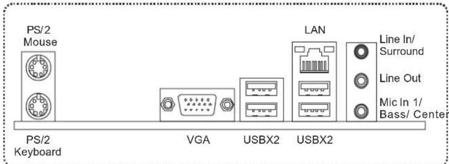
Since the audio chip supports High Definition Audio Specification, the function of each audio jack can be defined by software. The input / output function of each audio jack listed above represents the default setting. However, when connecting external microphone to the audio port, please use the Line In (blue) and Mic In (Pink) audio jack.
1.5 MOTHERBOARD LAYOUT

Note: ■ represents the 1^st pin.
CHAPTER 2: HARDWARE INSTALLATION
2.1 INSTALLING CENTRAL PROCESSING UNIT (CPU)

natural_image
Diagram showing a computer processor layout with an inset view of its internal CPU socket (no text or labels present)Special Notice:
Remove Pin Cap before installation, and make good preservation for future use. When the CPU is removed, cover the Pin Cap on the empty socket to ensure pin legs won't be damaged.

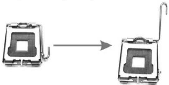
Step 1: Pull the socket locking lever out from the socket and then raise the lever up to a 90-degree angle.
natural_image
Two identical electronic device components with a curved arm, shown in sequential motion (no text or symbols)Motherboard Manual
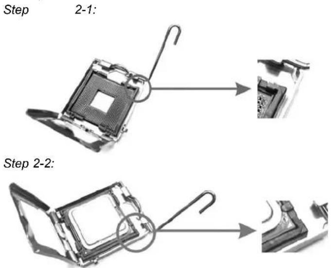
Step 2: Look for the triangular cut edge on socket, and the golden dot on CPU should point forwards this triangular cut edge. The CPU will fit only in the correct orientation.
Step 3: Hold the CPU down firmly, and then lower the lever to locked position to complete the installation.

natural_image
Metallic electronic component with a curved metal bracket and central square housing (no visible text or symbols)Step 4: Put the CPU Fan and heatsink assembly on the CPU and buckle it on the retention frame. Connect the CPU FAN power cable into the CPU_FAN1. This completes the installation.
2.2 FAN HEADERS
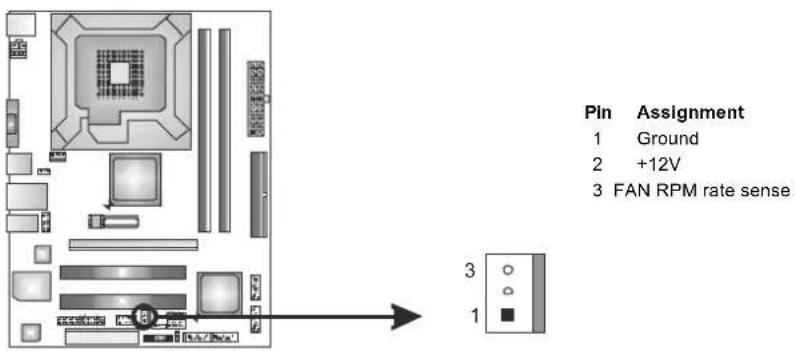
These fan headers support cooling-fans built in the computer. The fan cable and connector may be different due to the fan manufacturer. Connect the fan cable to the connector while matching the black wire to pin#1.
CPU_FAN1: CPU Fan Header

SYS_FAN1: System Fan Header
Note:
CPU_FAN1 supports 4-pin head connector; SYS_FAN1, 3-pin head one. When connecting with wires onto connectors, please note that the red wire is the positive and should be connected to pin#2, and the black wire is Ground and should be connected to GND.
2.3 INSTALLING SYSTEM MEMORY
A. DDR3 module

- Unlock a DIMM slot by pressing the retaining clips outward. Align a DIMM on the slot such that the notch on the DIMM matches the break on the Slot.

natural_image
Close-up of a computer RAM module with multiple slots and connectors (no visible text or symbols)- Insert the DIMM vertically and firmly into the slot until the retaining chip snap back in place and the DIMM is properly seated.

natural_image
Close-up of a computer RAM module with multiple drive bays and connectors (no visible text or labels)B. Memory Capacity
| DIMM Socket Location | DDR3 Module | Total Memory Size |
| DDR3_A1 | 256MB/512MB/1GB/2GB/4GB | Max is 8GB. |
| DDR3_B1 | 256MB/512MB/1GB/2GB/4GB |
C. Dual Channel Memory Installation
Please refer to the following requirements to activate Dual Channel function:
Install memory module of the same density in pairs, shown in the table.
| Dual Channel Status | DDR3_A1 | DDR3_B1 |
| Disabled | O | X |
| Disabled | X | O |
| Enabled | O | O |
(O means memory installed; X, not installed.)
The DRAM bus width of the memory module must be the same(x8 or x16)
2.4 CONNECTORS AND SLOTS
FDD1: Floppy Disk Connector
The motherboard provides a standard floppy disk connector that supports 360K, 720K, 1.2M, 1.44M and 2.88M floppy disk types. This connector supports the provided floppy drive ribbon cables.

IDE1: Hard Disk Connector
The motherboard has a 32-bit Enhanced PCI IDE Controller that provides PIO Mode 0\~4, Bus Master, and Ultra DMA 33/66/100 functionality.
The IDE connector can connect a master and a slave drive, so you can connect up to two hard disk drives.

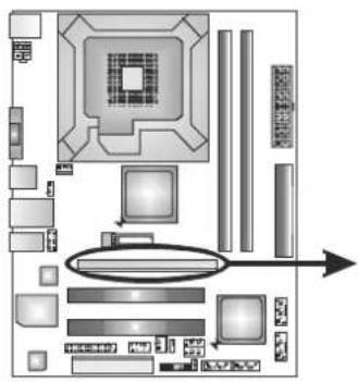
PEX16\_1: PCI-Express x16 Slot
- PCI-Express 1.0a compliant.
- Maximum theoretical realized bandwidth of 4GB/s simultaneously per direction, for an aggregate of 8GB/s totally.
- PCI-Express supports a raw bit-rate of 2.5Gb/s on the data pins.
- 2X bandwidth over the traditional PCI architecture.
PEX16 1
PCI1/PCI2: Peripheral Component Interconnect Slots
This motherboard is equipped with 2 standard PCI slots. PCI stands for Peripheral Component Interconnect, and it is a bus standard for expansion cards. This PCI slot is designated as 32 bits.

natural_image
Top-down schematic of a computer motherboard layout with CPU socket, drive bays, and indicator lights (no text or labels)PCI1
PCI2
CHAPTER 3: HEADERS & JUMPERS SETUP
3.1 HOW TO SETUP JUMPERS
The illustration shows how to set up jumpers. When the jumper cap is placed on pins, the jumper is "close", if not, that means the jumper is "open".
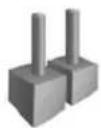
Pin
opened
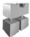
Pin
closed

Pin1-2
closed
3.2 DETAIL SETTINGS
PANEL1: Front Panel Header
This 16-pin connector includes Power-on, Reset, HDD LED, Power LED, and speaker connection. It allows user to connect the PC case's front panel switch functions.

| Pin | Assignment | Function | Pin Assignment | Function | ||
| 1 | +5V 9 | N/ASpeaker Connector | N/A | |||
| 2 | N/A | 10 | N/A | |||
| 3 | N/A | 11 | N/A | N/A | ||
| 4 | Speaker | 12 | Power LED (+) | Power LED | ||
| 5 | HDD LED (+) | Hard drive LED | 13 | Power LED (+) | ||
| 6 | HDD LED (-) | 14 | Power LED (-) | |||
| 7 | Ground | Reset button | 15 | Power button | Power-on button | |
| 8 | Reset control | 16 | Ground | |||
ATXPWR1: ATX Power Source Connector
This connector allows user to connect 24-pin power connector on the ATX power supply.

| Pin | Assignment | Pin | Assignment | |
| 13 | +3.3V | 1 | +3.3V | |
| 14 | -12V | 2 | +3.3V | |
| 15 | Ground | 3 | Ground | |
| 16 | PS_ON | 4 | +5V | |
| 17 | Ground | 5 | Ground | |
| 18 | Ground | 6 | +5V | |
| 19 | Ground | 7 | Ground | |
| 20 | NC | 8 | PW_OK | |
| 21 | +5V | 9 | Standby Voltage+5V | |
| 22 | +5V | 10 | +12V | |
| 23 | +5V | 11 | +12V | |
| 24 | Ground | 12 | +3.3V | |
ATXPWR2: AT X Power Source Connector
This connector provides +12V to CPU power circuit.

Note:
Before you power on the system, please make sure that both ATXPWR1 and ATXPWR2 connectors have been plugged-in.
F USB1/F USB2: Headers for USB 2.0 Ports at Front Panel
This motherboard provides 2 USB 2.0 headers, which allows user to connect additional USB cable on the PC front panel, and also can be connected with internal USB devices, like USB card reader.

| Pin | Assignment |
| 1 | +5V (fused) |
| 2 | +5V (fused) |
| 3 | USB- |
| 4 | USB- |
| 5 | USB+ |
| 6 | USB+ |
| 7 | Ground |
| 8 | Ground |
| 9 | Key |
| 10 | NC |
F AUDIO1: Front Panel Audio Header
This header allows user to connect the front audio output cable with the PC front panel. This header allows only HD audio front panel connector; AC'97 connector is not acceptable.

Pin Assignment
| 1 | Mic Left in | |
| 2 | Ground | |
| 3 | Mic Right in | |
| 4 | GPIO | |
| 5 | Right line in | |
| 6 | Jack | Sense |
| 7 | Front | Sense |
| 8 | Key | |
| 9 | Left line in | |
| 10 | Jack | Sense |
JCMOS1: Clear CMOS Header
Placing the jumper on pin2-3 allows user to restore the BIOS safe setting and the CMOS data. Please carefully follow the procedures to avoid damaging the motherboard.


Pin 1-2 Close: Normal Operation (Default).

Pin 2-3 Close: Clear CMOS data.
- Remove AC power line.
- Set the jumper to "Pin 2-3 close".
- Wait for five seconds.
- Set the jumper to "Pin 1-2 close".
- Power on the AC.
- Reset your desired password or clear the CMOS data.
SATA1\~SATA4: Serial ATA Connectors
The motherboard has a PCI to SATA Controller with 4 channels SATA interface, it satisfies the SATA 2.0 spec and with transfer rate of 3Gb/s.
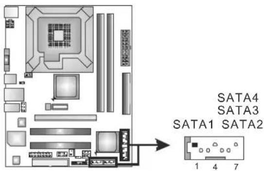
| Pin | Assignment |
| 1 | Ground |
| 2 | TX+ |
| 3 | TX- |
| 4 | Ground |
| 5 | RX- |
| 6 | RX+ |
| 7 | Ground |
JUSBV1/JUSBV2: Power Source Headers for USB Ports
Pin 1-2 Close:
JUSBV1: +5V for USB ports at USB1/RJ45USB1.
JUSBV2: +5V for USB ports at F_USB1/F_USB2.
Pin 2-3 Close:
JUSBV1: +5V STB for USB ports at USB1/RJ45USB1.
JUSBV2: +5V STB for USB ports at F_USB1/F_USB2.

J\_COM1: Serial port Connector
The motherboard has a Serial Port Connector for connecting RS-232 Port.
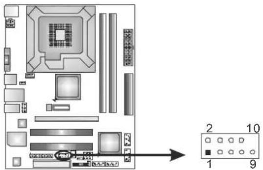
Pin Assignment
1 Carrier detect
2 Received data
3 Transmitted data
4 Data terminal ready
5 Signal ground
6 Data set ready
7 Request to send
8 Clear to send
9 Ring indicator
10 Key
J PRINT1: Printer Port Connector
This header allows you to connector printer on the PC.

| Pin | Assignment | Pin | Assignment | ||
| 1 | -Strobe | 14 | Ground | ||
| 2 | -ALF | 15 | Data | 6 | |
| 3 | Data 0 | 16 | Ground | ||
| 4 | -Error | 17 | Data | 7 | |
| 5 | Data 1 | 18 | Ground | ||
| 6 | -Init | 19 | -ACK | ||
| 7 | Data 2 | 20 | Ground | ||
| 8 | -Scltin | 21 | Busy | ||
| 9 | Data 3 | 22 | Ground | ||
| 10 | Ground | 23 | PE | ||
| 11 | Data 4 | 24 | Ground | ||
| 12 | Ground | 25 | SCLT | ||
| 13 | Data 5 | 26 | Key | ||
CHAPTER 4: USEFUL HELP
4.1 DRIVER INSTALLATION NOTE
After you installed your operating system, please insert the Fully Setup Driver CD into your optical drive and install the driver for better system performance.
You will see the following window after you insert the CD

The setup guide will auto detect your motherboard and operating system.
Note:
If this window didn't show up after you insert the Driver CD, please use file browser to locate and execute the file SETUP.EXE under your optical drive.
A. Driver Installation
To install the driver, please click on the Driver icon. The setup guide will list the compatible driver for your motherboard and operating system. Click on each device driver to launch the installation program.
B. Software Installation
To install the software, please click on the Software icon. The setup guide will list the software available for your system, click on each software title to launch the installation program.
C. Manual
Aside from the paperback manual, we also provide manual in the Driver CD. Click on the Manual icon to browse for available manual.
Note:
You will need Acrobat Reader to open the manual file. Please download the latest version of Acrobat Reader software from http://www.adobe.com/products/acrobat/readstep2.html
4.2 SOFTWARE
Installing Software
- Insert the Setup CD to the optical drive. The drivers installation program would appear if the Autorun function has been enabled.
- Select Software Installation, and then click on the respective software title.
- Follow the on-screen instructions to complete the installation.
Launching Software
After the installation process, you will see the software icon "eHOT Line" / "BIOS Update" appears on the desktop. Double-click the icon to launch the utility.
eHot-Line (Optional)
eHot-Line is a convenient utility that helps you to contact with our Tech-Support system. This utility will collect the system information which is useful for analyzing the problem you may have encountered, and then send these information to our tech-support department to help you fix the problem.

Before you use this utility, please set Outlook Express as your default e-mail client application program.

After filling up this information, click "Send" to send the mail out. A warning dialog would appear asking for your confirmation; click "Send" to confirm or "Do Not Send" to cancel.

If you want to save this information to a .txt file, click "Save As..." and then you will see a saving dialog appears asking you to enter file name.
Enter the file name and then click "Save". Your system information will be saved to a .txt file.

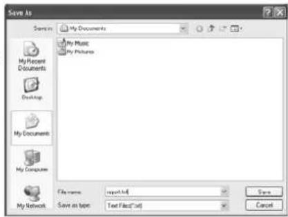
Open the saved .txt file, you will see your system information including motherboard/BIOS/CPU/video/device/OS information. This information is also concluded in the sent mail.

We will not share customer's data with any other third parties, so please feel free to provide your system information while using eHot-Line service.

If you are not using Outlook Express as your default e-mail client application, you may need to save the system information to a .txt file and send the file to our tech support with other e-mail application. Go to the following web http://www.biostar.com.tw/app/en-us/about/contact.php for getting our contact information.
BIOS Update
BIOS Update is a convenient utility which allows you to update your motherboard BIOS under Windows system.

Once click on this button, the saving dialog will show. Choose the position to save file and enter file name. (We recommend that the file name should be English/number and no longer than 7 characters.) Then click Save.

Before doing this, please download the proper BIOS file from the website.
For AWARD BIOS, update BIOS procedure should be run with Clear CMOS function, so please check on Clear CMOS first.


Then click Update BIOS button, a dialog will show for asking you backup current BIOS. Click Yes for BIOS backup and refer to the Backup BIOS procedure; or click No to skip this procedure.
After the BIOS Backup procedure, the open dialog will show for requesting the BIOS file which is going to be updated. Please choose the proper BIOS file for updating, then click on Open.


The utility will update BIOS with the proper BIOS file, and this process may take minutes. Please do not open any other applications during this process.
After the BIOS Update process, click on OK to restart the system.

While the system boots up and the full screen logo shows, press
In the BIOS setup, use the Load Optimized Defaults function and then Save and Exit Setup to exit BIOS setup. BIOS Update is completed.

All the information and content above about the software are subject to be changed without notice. For better performance, the software is being continuously updated. The information and pictures described above are for your reference only. The actual information and settings on board may be slightly different from this manual.
4.3 EXTRA INFORMATION
CPU Overheated
If the system shutdown automatically after power on system for seconds, that means the CPU protection function has been activated.
When the CPU is over heated, the motherboard will shutdown automatically to avoid a damage of the CPU, and the system may not power on again.
In this case, please double check:
- The CPU cooler surface is placed evenly with the CPU surface.
- CPU fan is rotated normally.
- CPU fan speed is fulfilling with the CPU speed.
After confirmed, please follow steps below to relief the CPU protection function.
- Remove the power cord from power supply for seconds.
- Wait for seconds.
- Plug in the power cord and boot up the system.
Or you can:
- Clear the CMOS data.
(See "Close CMOS Header: JCMOS1" section) - Wait for seconds.
- Power on the system again.
BIO-Flasher
BIO-Flasher is a BIOS flashing utility providing you an easy and simple way to update your BIOS via USB pen drive or floppy disk.
The BIO-Flasher is built in the BIOS chip. To enter the utility, press
Updating BIOS with BIO-Flasher
- Go to the website to download the latest BIOS file for the motherboard.
- Then, save the BIOS file into a USB pen drive or a floppy disk.
- Insert the USB pen drive or the floppy disk that contains the BIOS file to the USB port or the floppy disk drive.
- Power on or reset the computer and then press
during the POST process. A select dialog as the picture on the right appears. Select the device contains the BIOS file and press to enter the utility.
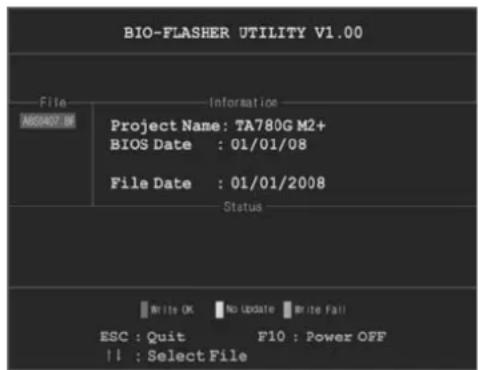

-
The utility will show the BIOS files and their respective information. Select the proper BIOS file and press
then to perform the BIOS update process. -
After the update process, the utility will ask you to reboot the system. Press
to proceed. BIOS update completes.

- This utility only allows storage device with FAT32/16 format and single partition.
- Shutting down or resetting the system while updating the BIOS will lead to system boot failure.
4.4 AMI BIOS BEEP CODE
Boot Block Beep Codes
| Number of Beeps | Description |
| 1 No media present. (Insert diskette in floppy drive A:) | |
| 2 | “AMIBOOT.ROM” file not found in root directory of diskette in A: |
| 3 Insert next diskette if multiple diskettes are used for recovery | |
| 4 Flash Programming successful | |
| 5 File read error | |
| 7 No Flash EPROM detected | |
| 10 Flash Erase error | |
| 11 Flash Program error | |
| 12 “AMIBOOT.ROM” file size error | |
| 13 | BIOS ROM image mismatch (file layout does not match image present in flash device) |
POST BIOS Beep Codes
| Number of Beeps | Description |
| 1 Memory refresh timer error | |
| 3 Base memory read/write test error | |
| 6 Keyboard controller BAT command failed | |
| 7 General exception error (processor exception interrupt error) | |
| 8 Display memory error (system video adapter) | |
Troubleshooting POST BIOS Beep Codes
| Number of Beeps | Troubleshooting Action |
| 1, 3 Reseat | the memory, or replace with known good modules. |
| 6, 7 | Fatal error indicating a serious problem with the system. Consult your system manufacturer. Before declaring the motherboard beyond all hope, eliminate the possibility of interference by a malfunctioning add-in card. Remove all expansion cards except the video adapter.If beep codes are generated when all other expansion cards are absent, consult your system manufacturer's technical support.If beep codes are not generated when all other expansion cards are absent, one of the add-in cards is causing the malfunction. Insert the cards back into the system one at a time until the problem happens again. This will reveal the malfunctioning card. |
| 8 | If the system video adapter is an add-in card, replace or reseat the video adapter. If the video adapter is an integrated part of the system board, the board may be faulty. |
4.5 TROUBLESHOOTING
| Probable | Solution |
| 1. There is no power in the system.Power LED does not shine; the fan of the power supply does not work2. Indicator light on keyboard does not shine. | 1. Make sure power cable is securely plugged in.2. Replace cable.3. Contact technical support. |
| System is inoperative. Keyboard lights are on, power indicator lights are lit, and hard drives are running. | Using even pressure on both ends of the DIMM, press down firmly until the module snaps into place. |
| System does not boot from a hard disk drive, but can be booted from optical drive. | 1. Check cable running from disk to disk controller board. Make sure both ends are securely plugged in; check the drive type in the standard CMOS setup.2. Backing up the hard drive is extremely important. All hard disks are capable of breaking down at any time. |
| System only boots from an optical drive. Hard disks can be read, applications can be used, but system fails to boot from a hard disk. | 1. Back up data and applications files.2. Reformat the hard drive.Re-install applications and data using backup disks. |
| Screen message shows “Invalid Configuration” or “CMOS Failure.” | Review system’s equipment. Make sure correct information is in setup. |
| System cannot boot after user installs a second hard drive. | 1. Set master/slave jumpers correctly.2. Run SETUP program and select correct drive types. Call the drive manufacturers for compatibility with other drives. |
This page is intentionally left blank.
APPENDIX: SPEC IN OTHER LANGUAGES
GERMAN
- FCC Information and Copyright
- Table of Contents
- Chapter 1: Introduction....1
- Chapter 2: Hardware Installation .... 5
- Chapter 3: Headers & Jumpers Setup .... 12
- Chapter 4: Useful Help ...... 18
- Appendix: SPEC In Other Languages 28
- CHAPTER 1: INTRODUCTION
- B EFORE YOU START
- PACKAGE CHECKLIST
- REAR PANEL CONNECTORS
- CHAPTER 2: HARDWARE INSTALLATION
- INSTALLING CENTRAL PROCESSING UNIT (CPU)
- Special Notice:
- Motherboard Manual
- FAN HEADERS
- Note:
- INSTALLING SYSTEM MEMORY
- Memory Capacity
- Dual Channel Memory Installation
- CONNECTORS AND SLOTS
- FDD1: Floppy Disk Connector
- IDE1: Hard Disk Connector
- PEX16\_1: PCI-Express x16 Slot
- PCI1/PCI2: Peripheral Component Interconnect Slots
- CHAPTER 3: HEADERS & JUMPERS SETUP
- HOW TO SETUP JUMPERS
- DETAIL SETTINGS
- PANEL1: Front Panel Header
- ATXPWR1: ATX Power Source Connector
- ATXPWR2: AT X Power Source Connector
- F USB1/F USB2: Headers for USB 2.0 Ports at Front Panel
- F AUDIO1: Front Panel Audio Header
- Pin Assignment
- JCMOS1: Clear CMOS Header
- SATA1\~SATA4: Serial ATA Connectors
- JUSBV1/JUSBV2: Power Source Headers for USB Ports
- J\_COM1: Serial port Connector
- J PRINT1: Printer Port Connector
- CHAPTER 4: USEFUL HELP
- DRIVER INSTALLATION NOTE
- Driver Installation
- Software Installation
- Manual
- SOFTWARE
- Installing Software
- Launching Software
- eHot-Line (Optional)
- BIOS Update
- EXTRA INFORMATION
- CPU Overheated
- BIO-Flasher
- Updating BIOS with BIO-Flasher
- AMI BIOS BEEP CODE
- APPENDIX: SPEC IN OTHER LANGUAGES
Brand : BIOSTAR
Model : G41D3+
Category : Motherboard