TR-1518 - Tripod Winegard - Free user manual and instructions
Find the device manual for free TR-1518 Winegard in PDF.

| Product Type | Tripod |
| Brand | Winegard |
| Model | TR-1518 |
| Height (Fully Extended) | 5 feet (1.5 m) |
| Height (Collapsed) | 3 feet (0.9 m) |
| Weight | 8 lbs (3.6 kg) |
| Material | Steel |
| Load Capacity | 100 lbs (45 kg) |
| Leg Sections | 3 |
| Leg Diameter | 1 inch (25 mm) |
| Mounting Plate | Universal with mounting holes |
| Locking Mechanism | Twist-lock collars |
| Feet | Rubber with spikes |
| Power Supply | None (manual operation) |
| Primary Function | Support antennas or equipment |
| Maintenance | Wipe with damp cloth, check for loose bolts |
| Safety | Do not exceed load capacity; use on level ground |
| Spare Parts | Rubber feet, locking collars available |
| Repairability | Modular legs and hardware |
| General Information | Designed for outdoor use; compatible with most Winguard antennas |
Frequently Asked Questions - TR-1518 Winegard
User questions about TR-1518 Winegard
0 question about this device. Answer the ones you know or ask your own.
Ask a new question about this device
Download the instructions for your Tripod in PDF format for free! Find your manual TR-1518 - Winegard and take your electronic device back in hand. On this page are published all the documents necessary for the use of your device. TR-1518 by Winegard.
USER MANUAL TR-1518 Winegard
Carryout® Tripod Mount
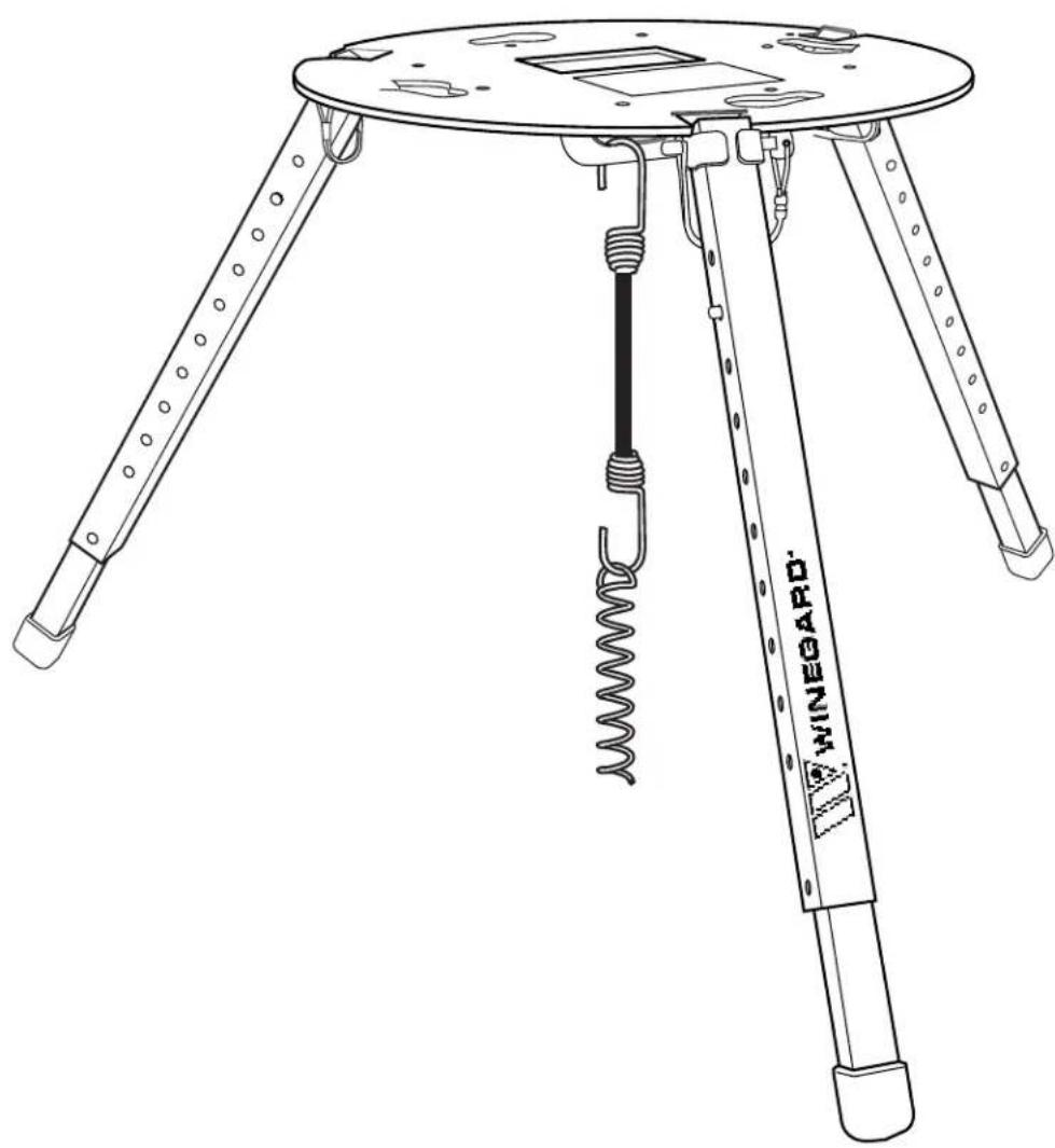
natural_image
Line drawing of a tripod-mounted scientific instrument with a coiled spring and labeled 'WINEGARD' (no text or symbols on the device itself)For Technical Services, email help@winegard.com or call 1-800-788-4417.
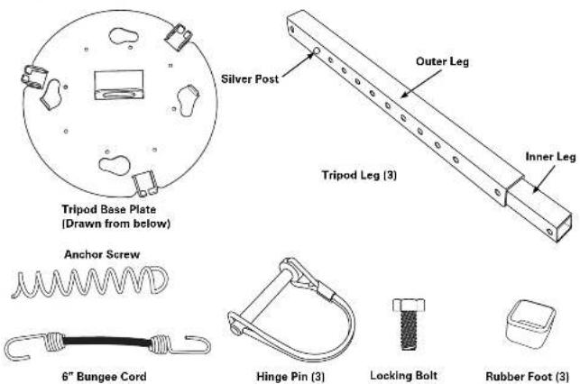
Tripod Mount Contents
CAUTION
The Carryout Tripod is designed only for use with portable satellite TV systems. The tripod has a maximum supported weight of 15 lbs. DO NOT use the tripod as a step or a seat.
Assembly
Step 1
Slide a rubber foot onto the end of the inner leg farthest from the silver posts on the leg, making sure to slide the foot onto the leg so that the bottom of the leg touches the bottom of the foot. Repeat this for each of the legs.
Step 2
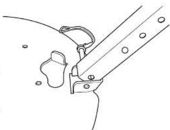
Next, attach the outer leg to the base plate. Pinch the silver post on the leg and slide it to the second notch. Line up the hole in the end of the leg without the rubber foot with the hole in the tripod base plate shown to the right.
Once the holes are lined up, carefully insert a hinge pin into these holes. You may need to slowly rock the leg back and forth slightly to help get the pin all the way through. Once the hinge pin is holding the leg in place, snap the lock over the pin to keep it from working loose.
Repeat this step for each leg.
natural_image
Line drawing of a mechanical clamp or bracket assembly (no text or symbols)Choosing a Location for the System
Your satellite system requires a clear view of the southern sky. Avoid obstructions such as vehicles, trees and buildings that may block the system's view of the satellites. Make sure you select a location for the tripod away from walking traffic to prevent the tripod from becoming a safety/tripping hazard.
Try to select a fairly level location for the tripod. While the tripod is designed to handle uneven surfaces, choosing a level surface will make setup easier.
Setup
Make sure that the tripod base plate is level before attaching the satellite antenna. Gently grab and pull the legs away from the center of the tripod until you feel the stop. This will improve the stability of the unit.
Level the base plate. It may be necessary to extend one or more of the tripod legs. To do this, pinch the silver posts sticking out from the side of the tripod leg, and pull the inner leg at the same time. Repeat as needed to level the unit, DO NOT USE THE BOTTOM HOLE IN THE OUTSIDE TUBE LEG.
If you have selected a location for the tripod on dirt or grass, you can secure the tripod by using the anchor screw and bungee provided. Simply twist the anchor screw into the ground beneath the tripod, and attach the bungee cord to the anchor. Then, connect the other end of the bungee cord to the restraining loop in the base plate.
If you have selected a location for the tripod that is on a surface that will not accept the anchor screw, you can attach a weight of approximately 8 lbs to the bungee cord in order to help keep the unit stable (a gallon of water weighs approximately 8 lbs).
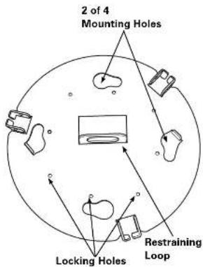
To install a satellite antenna on the tripod mount, line up the feet of the satellite antenna with the four mounting holes in the base plate of the tripod. See the image below.
NOTE If installing the Carryout Anser antenna on the tripod, the antenna feet must be installed in the inside holes of the antenna base. If installed in the outside holes of the base, move the feet to the inside holes.
Rotate the satellite antenna counterclockwise to lock it into place.
When installing a Carryout antenna, use the locking bolt provided to secure the Carryout to the tripod by threading the bolt from beneath the tripod base up into the bottom of the Carryout unit. Refer to the image on the right.
NOTE Depending on the orientation of the antenna on the tripod, the locking hole that you use may change. Find the locking hole in the tripod that lines up with the hole in the antenna base.
Packing up the Tripod
When you are finished using the satellite antenna, simply remove it from the tripod by removing the locking bolt and rotating the satellite system a quarter turn clockwise. Lift the satellite system from the tripod. Reinstall the locking bolt in the threaded hole in the base of the antenna.
With the satellite system removed, unclip the bungee cord from the anchor screw and unscrew the anchor.
Finally, remove the legs by unlocking the hinge pins and pulling them from the unit.
It is a good idea to reattach the hinge pins to the legs for storage. This make it easier to find them when you are ready to use your tripod again.
WINEGARD MOBILE PRODUCTS LIMITED WARRANTY (2 YEARS PARTS; 1 YEAR LABOR)
Winegard Company warrants this product against defects in materials or workmanship for a period of two (2) years from the date of original purchase. During year one (1) of such warranty, Winegard Company will also pay authorized labor costs to an authorized Winegard dealer to repair or replace defective products. No warranty claim will be honored unless at the time the claim is made, Customer presents proof of purchase to an authorized Winegard dealer (to locate the nearest authorized Winegard dealer, contact Winegard Company, 3000 Kirkwood Street, Burlington, Iowa 52601, Telephone 800-288-8094 or visit www.winegard.com). Customer must provide proof of purchase with a dated sales receipt for the Winegard product to verify the product is under warranty. If the date of purchase cannot be verified, the warranty period shall be considered to begin thirty (30) days after the date of manufacture.
If a defect in material or workmanship is discovered, Customer may take the product to an authorized Winegard dealer for service. Customer must provide proof of purchase to verify the product is under warranty. If the product is brought to an authorized Winegard dealer for service prior to expiration of year one (1) of the warranty period and a defect in material or workmanship is verified by Winegard Technical Services, Winegard Company will cover the Winegard dealer's labor charges for warranty service. The Winegard dealer must contact Winegard Technical Services in advance for pre-approval of the service. Approval of the service is at the sole discretion of Winegard Company.
Alternatively, Customer may ship the product prepaid to Winegard Technical Services (located at 3111 Kirkwood Street, Burlington, Iowa 52601, Telephone 800-788-4417). Customer must return the product along with a brief description of the problem and provide Winegard Technical Services with Customer's name, address, and phone number. Customer must also provide proof of purchase to verify the product is under warranty. If the product is returned before the expiration of the warranty period, Winegard Company will (at its option) either repair or replace the product.
This Limited Warranty does not apply if the product has been damaged, deteriorates, malfunctions or fails from: improper installation, misuse, abuse, neglect, accident, tampering, modification of the product as originally manufactured by Winegard in any manner whatsoever, removing or defacing any serial number, usage not in accordance with product instructions or acts of nature such as damage caused by wind, lightning, ice or corrosive environments such as salt spray and acid rain. This Limited Warranty also does not apply if the product becomes unable to perform its' intended function in any way as a result of the television signal provider making any changes in technology or service.
RETURN AUTHORIZATION POLICY
A Return Material Authorization (RMA) is required prior to returning any product to Winegard Company or Winegard Warranty Services under this warranty policy. Please call our Technical Services Department at 800-788-4417 or send an e-mail to warranty@winegard.com to obtain the RMA number. Please furnish the date of purchase when requesting an RMA number. Enclose the product in a prepaid package and write the RMA number in large, clear letters on the outside of the package. To avoid confusion or misunderstanding, a shipment(s) without an RMA number(s) or an unauthorized return(s) will be refused and returned to Customer freight collect.
WINEGARD COMPANY DOES NOT ASSUME ANY LIABILITIES FOR ANY OTHER WARRANTIES, EXPRESS OR IMPLIED, MADE BY ANY OTHER PERSON.
ALL OTHER WARRANTIES WHETHER EXPRESS, IMPLIED OR STATUTORY INCLUDING WARRANTIES OF FITNESS FOR A PARTICULAR PURPOSE AND MERCHANTABILITY ARE LIMITED TO THE TWO YEAR PERIOD OF THIS WARRANTY.
In states that do not allow limitations on implied warranties, or the exclusion of limitation of incidental or consequential damages, the above limitations or exclusions do not apply.
Some states do not allow limitations on how long an implied warranty lasts, or the exclusion of limitation of incidental or consequential damages, so the above limitations or exclusions may not apply to you.
This warranty gives Customer specific legal rights. Customer may also have other rights that may vary from state to state.
SATELLITE RECEIVER WARRANTY
See manufacturer's limited warranty policy.
WS-MOBWARREV2
Rev. 1/10

WINEGARD®
For Technical Services, email help@winegard.com or call 1-800-788-4417.
Winegard Company • 3000 Kirkwood Street • Burlington, IA 52601
800-288-8094 • Fax 319-754-0787 • www.winegard.com • Printed in U.S.A.
©2009 Winegard Company Rev4 8/12 2452180
Winegard and Carryout are registered trademarks of Winegard Company.
Disclaimer: Although every effort has been made to ensure that the information in this manual is correct and complete, no company shall be held liable for any errors or omissions in this manual. Information provided in this manual was accurate at time of printing.