Prostar PR-7015 - TV antenna Winegard - Free user manual and instructions
Find the device manual for free Prostar PR-7015 Winegard in PDF.

| Product Type | TV Antenna |
| Brand | Winegard |
| Model | Prostar PR-7015 |
| Dimensions | Approx. 20 x 10 x 3 inches |
| Weight | Approx. 2 lbs |
| Power Source | Passive (no external power required) |
| Frequency Reception | UHF (470-698 MHz) and VHF (54-216 MHz) |
| Beam Angle | 360-degree (omnidirectional) or directional depending on model |
| Maximum Range | Up to 60 miles (depending on terrain and interference) |
| Mount Type | Indoor/outdoor mast mount |
| Weather Resistance | UV-resistant and waterproof (suitable for outdoor use) |
| Connector Type | F-type coaxial (75 ohms) |
| Cable Length | Not included; standard RG6 recommended |
| Warranty | 1 year limited |
| Maintenance | Wipe with a soft, dry cloth; avoid abrasive cleaners |
| Safety Precautions | Install away from power lines and electrical cables; ensure stable mounting |
| Compatibility | Compatible with all digital TV broadcasts (ATSC 1.0) |
Frequently Asked Questions - Prostar PR-7015 Winegard
User questions about Prostar PR-7015 Winegard
0 question about this device. Answer the ones you know or ask your own.
Ask a new question about this device
Download the instructions for your TV antenna in PDF format for free! Find your manual Prostar PR-7015 - Winegard and take your electronic device back in hand. On this page are published all the documents necessary for the use of your device. Prostar PR-7015 by Winegard.
USER MANUAL Prostar PR-7015 Winegard
ATTACHING COAX FOR PR- MODELS
STEP 4. Be sure to unfold tetrapole elements away from boom. Loosen wing nuts on downlead connections. Attach matching transformer ends to the studs between the washers and tighten wing nuts. See Figure 8.
ATTACHING COAX FOR MODEL HD7210P ONLY
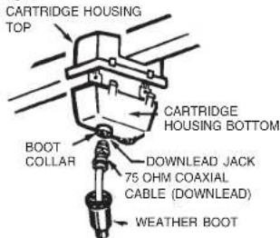
STEP 4. Attach the 75 ohm coaxial downlead to the housing. Slide weather boot over the boot collar. See Figure 9.
ATTACHING ANTENNA TO MAST
Loosen U-bolt nuts. Slide U-bolt over mast. Point small end of antenna toward stations and tighten securely. See Figure 10. Install a second U-bolt for antennas with multiple booms. The 75 ohm coaxial cable download may be secured to mast by taping or by using plastic wire ties.
HOW TO PROVIDE LIGHTNING PROTECTION FOR TV ANTENNA AND SET
Step 1. Mount the grounding block as close as possible to where the 75 ohm coaxial cable downlead enters the house. See Figure 11.
Step 2. The ground wires for both the mast and the downlead should be copper or aluminum wire, number eight (8) or larger. See Figure 11.
Step 3. The downlead wire from the antenna to the grounding block and the mast ground wire should be secured to the house spaced from four (4) to six (6) feet apart. See Figure 11.
NOTE: In the case of a "ground up" antenna installation, it may not be necessary to ground the mast if the mast extends four or more feet into the earth. Consult a TV serviceman for the proper depth in your location.
Fig. 8
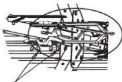
natural_image
Technical line drawing of a mechanical assembly with no visible text or symbolsATTACH DOWNLEAD/MATCHING TRANSFORMER HERE
Fig. 9
Fig. 10
MAST CLAMP
HEX NUT
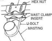
Fig. 11
Example of antenna grounding as per National Electrical Code, ANS/NFPA 70
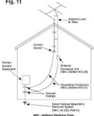
NEC - National Electrical Code
Printed in U.S.A. © Winegard Company 2003 1450172 Rev. 7/04
WINEGARD® High Definition (HD) Platinum Antennas
INSTRUCTIONS
VHF/UHF MODELS
HD7210P, PR-5646, PR-7000, PR-7005, PR-7010, PR-7013, PR-7015, PR-7032, PR-7037, PR-7042 & PR-7052
VHF ONLY
PR-5030, YA-1026, YA-1713, YA-6260 & YA-6713
WARNING
INSTALLATION OF THIS ANTENNA NEAR POWER LINES IS DANGEROUS. FOR YOUR SAFETY, FOLLOW THE INSTALLATION INSTRUCTIONS.
90 DAY LIMITED WARRANTY
Winegard Company warrants this Winegard product against any defects in materials or workmanship within 90 (ninety) days from date of purchase. No warranty claim will be honored unless at the time the claim is made, you present proof of purchase to an authorized Winegard dealer (if unknown, please contact Winegard Company, 3000 Kirkwood Street, Burlington, IA 52601-2000, Telephone 319-754-0600).
Winegard Company (at its option) will either repair or replace the defective product at no charge to you. This warranty covers parts, but does not cover any costs incurred in removal, shipping or reinstallation of the product. This limited warranty does not apply if the product is damaged, deteriorates, malfunctions or fails from: misuse, improper installation, abuse, neglect, accident, tampering, modification of the product as originally manufactured by Winegard, usage not in accordance with product instructions or acts of nature such as damage caused by wind, lighting, ice or corrosive environments such as salt spray and acid rain.
The 90 Day Warranty is provided on the condition that the equipment is properly delivered with all handling and freight charges prepaid to your Winegard dealer for return to our factory for repair or replacement. Winegard dealers will arrange for the replacement or repair and return to you without charge the product which failed due to defective material or workmanship.
WINEGARD COMPANY WILL NOT ASSUME ANY LIABILITIES FOR ANY OTHER WARRANTIES, EXPRESS OR IMPLIED, MADE BY ANY OTHER PERSON.
ALL OTHER WARRANTIES WHETHER EXPRESS, IMPLIED OR STATUTORY INCLUDING WARRANTIES OF FITNESS FOR A PARTICULAR PURPOSE AND MERCHANTABILITY ARE LIMITED TO THE 90-DAY PERIOD OF THIS WARRANTY.
The foregoing shall be the sole and exclusive remedy of any person, whether in contract, tort or otherwise, and Winegard shall not be liable for incidental or consequential damage or commercial loss, or from any other loss or damage except as set forth above.
Some states do not allow limitations on how long an implied warranty lasts, or the exclusion of limitation of incidental or consequential damages, so the above limitations or exclusions may not apply to you.
This warranty gives you specific legal rights and you may also have other rights which vary from state to state.
Winegard Company • 3000 Kirkwood Street • Burlington, IA 52601-2000
FOR MODELS WITH REFLECTOR BOOMS INSTALLED IN FACTORY
STEP 1. Remove antenna from carton and unfold elements on reflector booms until they lock into place. See Figure 1.
STEP 2. Unfold reflector booms until they lock into place. See Figure 1.
FOR ALL MODELS
STEP 3. Unfold all other elements until they lock into place. Be sure the elements are locked into position and are flat and parallel to each other. See Figure 2.
FOR TWO-PIECE BOOM MODELS
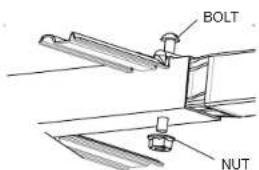
Remove nut and bolt from boom and slide narrow end of boom into end of larger section aligning bolt holes. See Figure 3. Re-install bolt and nut, being sure to tighten securely.
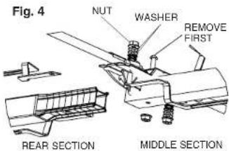
FOR MODELS PR-7042 & PR-7052
Repeat the step above for attaching front and middle sections. Repeat the same procedure for attaching the rear section to the middle. Then, remove the hex nuts and washers from the top and bottom of the first element holder studs on middle section. See Figure 4. Place the phasing lines from the rear section over the studs, one on top and the other on bottom, and re-attach the washers and hex nuts.
Fig. 1
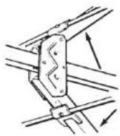
Fig. 2
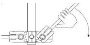
natural_image
Technical line drawing of a mechanical clamp or bracket assembly with a hand holding a tool (no text or symbols)Fig. 3
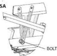
FOR MODELS WITH BOOM BRACES
STEP 1. Assemble antenna using previous steps. Lay boom brace on top of antenna with U-bolts on same side. Find the bolt hole in the corner reflector and attach brace with the bolt and nut provided. Swing boom brace down toward the rear. Form a "V" with the metal straps. Bolt the "V" to each side of boom. See Figures 5 and 5A.
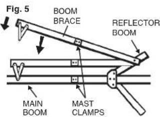
Fig. 5A
STUD HOLDER
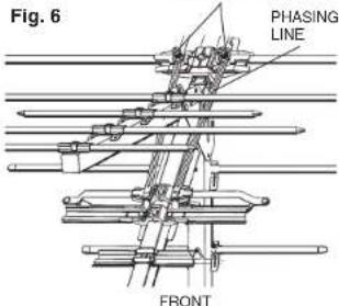
Fig. 7