
ENHWI-3GN3 - Router ENCORE - Free user manual and instructions
Find the device manual for free ENHWI-3GN3 ENCORE in PDF.


| Product Type | 3G/4G Mobile Router |
| Brand | ENCORE |
| Model | ENHWI-3GN3 |
| Dimensions (W x D x H) | 100 x 60 x 20 mm |
| Weight | 150 g |
| Power Supply | USB 5V/1A (via AC adapter or computer) |
| Battery | Built-in rechargeable lithium-ion, 1500 mAh |
| Wireless Standard | IEEE 802.11 b/g/n (2.4 GHz) |
| Mobile Network | 3G HSPA+ (up to 21 Mbps downlink) |
| Max. Users | Up to 10 simultaneous connections |
| Security | WPA/WPA2-PSK, WEP, MAC Filtering, SPI Firewall |
| Interfaces | 1 x SIM slot (standard), 1 x RJ-45 LAN, 1 x USB (for power/charging) |
| Buttons | Power, Reset |
| LED Indicators | Power, WiFi, 3G, Battery |
| Operating Temperature | 0°C to 40°C |
| Storage Temperature | -10°C to 70°C |
| Maintenance & Cleaning | Wipe with a soft, dry cloth. Do not use solvents. |
| Spare Parts & Repairability | Contact ENCORE support or authorized service centers. Only battery is user-replaceable. |
Frequently Asked Questions - ENHWI-3GN3 ENCORE
User questions about ENHWI-3GN3 ENCORE
0 question about this device. Answer the ones you know or ask your own.
Ask a new question about this device
Download the instructions for your Router in PDF format for free! Find your manual ENHWI-3GN3 - ENCORE and take your electronic device back in hand. On this page are published all the documents necessary for the use of your device. ENHWI-3GN3 by ENCORE.
USER MANUAL ENHWI-3GN3 ENCORE
natural_image
White wireless router with white antenna and red-orange gradient background (no visible text or symbols)ENHWI-3GN3
© 2010 Encore Electronics, Inc.
TABLE OF CONTENTS
1. INTRODUCTION ...... 2
1.1 SUMMARY....2
1.2 KEY FEATURES.... 3
1.3 PACKAGE CONTENTS 4
1.4 PRODUCT LAYOUT 5
2. INSTALLATION .... 7
2.1 NETWORK PLUS SYSTEM REQUIREMENTS....7
2.2 WALL MOUNTING 8
2.3 BEST LOCATION 8
2.4 SETTING UP LAN AND 3G (WAN) 9
2.5 PC NETWORK ADAPTER SETUP 10
2.6 POWERING UP THE ENHWI-3GN3 12
3. SMART WIZARD.... 13
4. HOW TO LOGIN TO THE WEB BASED USER INTERFACE ...... 26
5. AP ROUTER MODE.... 28
5.1 SYSTEM 28
5.2 WIZARD.... 34
5.3 INTERNET 35
5.4 WIRELESS SETTINGS 42
5.5 FIREWALL SETTINGS.... 56
5.6 ADVANCED SETTINGS 62
5.7 TOOLS SETTINGS.... 75
6. REPEATER MODE 81
6.1 SYSTEM 82
6.2 WIRELESS 86
6.3 TOOLS....89
7. TECHNICAL SUPPORT....94
APPENDIX A: FCC INTERFERENCE STATEMENT.... 94
APPENDIX B: IC INTERFERENCE STATEMENT.... 94
Product specifications, size, and shape are subject to change without notice, and actual product appearance may differ from that depicted herein.
All trademarks and brand names are the properties of their respective holders.
© 2010 Encore Electronics, Inc. All rights reserved.
1. INTRODUCTION
1.1 Summary
Thank You for patronizing another Encore product. The ENHWI-3GN3 is a 3G-enabled Wireless-N Router that supports home network with superior throughput, performance and unparalleled wireless range. With ENHWI-3GN3, you can share one 3G Wireless internet subscription to others through wired and wireless LAN. It supports 3G USB Modem Adapters from wide selections of 3G broadband carriers all over the world. A freedom to roam where your 3G cell subscription site is available and still share and enjoy the Wireless-N's speed and accuracy. Unlike other wireless 3G routers, the Encore's ENHWI-3GN3 comes with a WAN port. With WAN port, you are not limited to just 3G connection; you can still hook up your home or home-office DSL or Cable Modem broadband internet connections. With ENHWI-3GN3 you can provide a hot spot within home, office, apartment, school, café, construction site, etc. wherever your subscription 3G wireless ISP tower can roam.
With 2 LAN ports, you are not limited to a wireless LAN alone, you can use these ports for your wired network devices like Encore network printers, Encore Network Attached Storage and many more networking accessories. On top of the popular WPA, WPA2 and WEP wireless security the ENHWI-3GN3 is equipped with a one touch “push-n-connect” button wireless security using the latest WPS® technology. The Router function ties it all together and lets your whole network shares a high-speed cable, DSL or wireless 3G Broadband Internet connections.
The ENHWI-3GN3 is also a Wireless Repeater than can be used to extend your Wireless LAN to a remote area with one simple setup switching from Router to a Repeater Mode.
1.2 Key Features
| Features Advantages | |
| 3G USB Modem Support Allows user to share 3G network among multiple users. It supports WCDMA (HSDPA), CDMA2000 and TD-SCDMA. | |
| Incredible Data Rate up to 150Mbps** | Easily handles heavy data payloads such as MPEG video /audio streaming |
| IEEE 802.11b/g Compliant | Fully Interoperable with IEEE 802.11b / IEEE 802.11g compliant devices with legacy protection |
| Four 10/100 Mbps Fast Switch Ports (Auto-Crossover) | Scalability; extends your network. |
| Firewall supports, DMZ, MAC Filter, IP Filter, URL Filter, ICMP Blocking, SPI, Port Mapping, Port Forwarding, Port Trigger | To prevent attacks from hackers or virus from the internet, Parental Control and Internet Keyword Control |
| Support 802.1x Authenticator, 802.11i (WPA/WPA2, AES), VPN pass-through | Provides mutual authentication (Client and dynamic encryption keys to enhance security) |
| WDS (Wireless Distribution System) | Run wireless AP and Bridge modes simultaneously as a wireless repeater |
| Multiple SSID Easy management of users of various groups. | |
** Theoretical wireless signal rate based on IEEE standard of 802.11b / g / n chipset used. Actual throughput may vary. Network conditions and environmental factors lower actual throughput rate. All specifications are subject to change without notice.
1.3 Package Contents
Check and make sure that none of the items listed below are missing. Do not discard the packing materials, in case of return; the unit must be shipped back in its original packaging.
- ENHWI-3GN3 Router plus Repeater
- 100V\~240VAC / 12 VDC 1A External Power Adapter
- One piece 2 dBi 2.4 GHz R-SMA Upgradeable Antenna
- Quick Installation Guide leaflet
- CD-ROM (Smart Wizard and User's Manual)
- 2x Patch cables - 1x one foot patch cable (green) and one 3 Feet patch cable (yellow)
1.4 Product Layout
Front Panel View

Front Panel LED Assignments and Description Chart:
| LED Lights | Description |
 POWER POWER | Lights up in Red when powered ON. Blinks on TEST/RESET |
 WLAN WLAN | Lights up in Green when Wireless LAN is enabled. Blinks on traffic |
  LAN Ports LAN Ports | Blinks in Green on data traffic on LAN Ports 1 and 2. Stays in Green when idle |
 WAN WAN | Lights up in Green when WAN port is in use |
 3G Connection 3G Connection | Lights up in Green when 3G USB Modem is detected and use for internet connection |
 Internet Connection Internet Connection | Lights up and stays in Green when internet connection is detected thru either in 3G or WAN ports (WAN and 3G don't work at the same time, 3G deactivates WAN connection when both are detected, then this LED lights up for 3G if that happens) |
Rear View

Top View

| Item Description | |
| Reset | Press and release this button to reboot the device. Press and hold this button for 10 seconds to load the factory default settings of the system. |
| WPS Button Push-n-Connect | Press this button to start Push-n-Connect (WPS) function. |
| DC 12V | Power connector, connects to a DC 12V 1A Power Adapter (Supplied) |
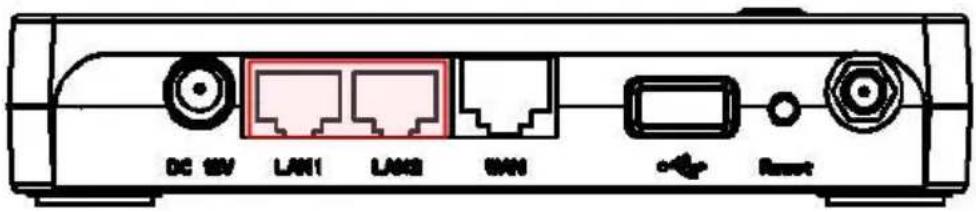
| LAN1and LAN2 | Ports 1 and 2 Local Area Network (LAN) 10/100 Mbps RJ-45 ports |
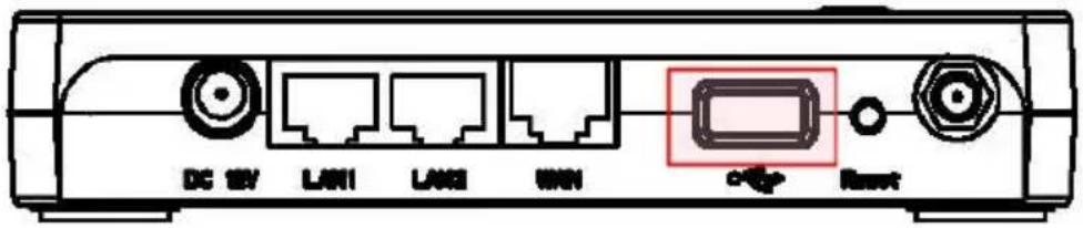
| USB Port | Used for 3G USB Modem (Not included) from your 3G ISP subscription |
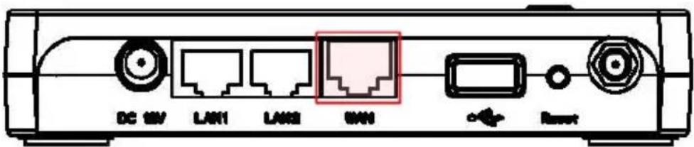
| WAN | Wide Area Network (WAN) port or Internet Port. Connects to xDSL or Cable Modem |
2. INSTALLATION
2.1 Network plus System Requirements
To begin using the ENHWI-3GN3, make sure you meet the following as minimum requirements:
▶ PC / Notebook Computer as client
Operating System – Microsoft™ Windows® 98SE/ME/XP/2000/Windows Vista™ / Windows® 7
▶ Computer with 1 working RJ-45 Network Interface Card port
Wi-Fi adapter card – (optional for Wireless LAN installation procedure)
▶ Internet connection (Subscription to your local ISP may be required)
○ External xDSL (ADSL) or Cable modem internet subscription with an Ethernet WAN port (RJ-45) or
- 3G USB Modem for Internet Connection
A Web Browser running Internet Explorer, Safari, Firefox, Opera etc.
▶ Ethernet compatible CAT5 or better cables.
2.2 Wall Mounting
Bottom View Showing Wall Mounts

The ENHWI-3GN3 is wall mountable. There are two mounting holes at the bottom of the router. Find a proper spot where two nails or wall screws can be applied. The distance between the two nails is 117 ~mm . Carefully mount the device onto the wall and make sure the router is firmly in place.
2.3 Best Location
You can place ENHWI-3GN3 on a desk or other flat surface, or you can mount it on a wall. For optimal performance, place your router in the center of your office (or your home) in a location that is away from any potential source of wireless interference, such as a metal wall or microwave oven. The preferred location should be close to a electrical power wall outlet. If the antennas are not positioned correctly, performance loss can occur.
2.4 Setting Up LAN and 3G (WAN)
LAN connection:
Connect Ethernet cable between your PC/Notebook LAN port & one of the 2 available LAN ports on ENHWI-3GN3.
3G connection:
Insert your 3G USB Modem to the USB Port for your 3G internet connections. contact your ISP or internet service provider for the 3G username and password and other 3G internet issues.
ADSL or Cable Modem Broadband Connection:
Connect an Ethernet cable between WAN ports of your ADSL/Cable modem and WAN port of ENHWI-3GN3. For internet to work, the ADSL/Cable modem should be working and configured. Contact your ISP or internet service provider for any internet connection question and support.
2.5 PC Network Adapter Setup
Windows XP
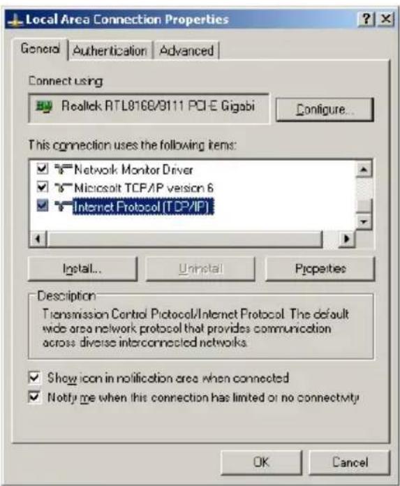
- Assuming your PC or Laptop is already equipped with a Network Interface Card and properly working. Click on START → select "Control panel" → From the Control Panel Window select "Network Connection"

- Right-click (Use the right button of your mouse) the "Local Area Connection" icon then select and click "Properties"

- Click to Highlight the "Internet Protocol (TCP/IP)" then click "Properties" button
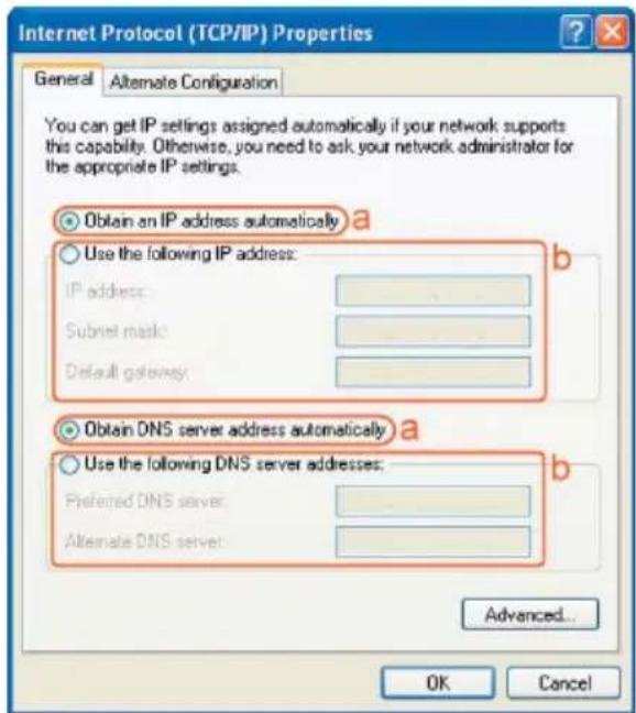
- Select the "General" tab.
The ENHWI-3GN3 supports DHCP Client function, select both “Obtain an IP address automatically” and “Obtain DNS server address automatically”
2.6 Powering Up The ENHWI-3GN3
Connect the supplied power-adapter to the power port and then plug it to a wall power outlet. The ENHWI-3GN3 automatically enters and run the self-test or initialization in just a few seconds. The Power LED will light a steady red light indicating that the ENHWI-3GN3 is ready for operation.
3. SMART WIZARD
Connects your computer to the ENHWI-3GN3 router
and set up basic settings the easy way
Before you start the ENHWI-3GN3 router's Smart Wizard, check for the followings:
It is recommended using the Ethernet cable connection when running the Smart Wizard for accuracy purposes.
- Internet connection should be running & ready for internet use (3G internet connection, ADSL or Cable modem).
- ADSL Modem or Cable Modem must have an RJ-45 LAN port, DSL or Cable modem usually are supplied by your ISP or Internet Service Provider
- Microsoft Windows compatible PC/Notebook with UPnP enabled Network Interface Card adapter. (This can be found in your network cards advanced properties within MS Windows) Optional, this is if you prefer to use the UPnP feature.
- CAT 5 or better network Ethernet cable(s) with RJ-45 connector for PC/Notebook connections. (** RJ-45 looks like a telephone cable connector but bigger)
Step 1:
- For DSL or Cable Broadband. Connect the ENHWI-3GN3 "WAN Port" & your Cable or DSL Modem's LAN port using the provided Blue Ethernet / RJ-45 patch cable.
- For 3G Internet. Connect the 3G USB Modem to the USB Port. (Note: It may take around 20 seconds for the router to recognize and initialize the 3G USB Modem.
Step 2: Connect any of the two available LAN ports to your PC or Notebook's RJ-45 network interface card port using the provided Yellow Ethernet cable.
Step 3: Power-on the ENHWI-3GN3 unit. The red power LED in the front the panel should light up & stay on to indicate that the router is ready.
Step 4: Bring up the Smart Wizard. The “Smart Wizard” is a user friendly step-by-step instruction to help you to initially set up your router to connect your computer(s) to the internet; it also guides you in setting up the administrator’s user ID and password, set up the ENHWI-3GN3 wireless security to protect your router and your LAN computers from hackers and other type of intrusions. Write down user ID and password, in case you forgot a hardware reset button can bring the settings back to the manufacturers default ID’s and the changes you made to the settings will be erased.
Insert the ENHWI-3GN3 Setup Disc CD into your computer's CDROM drive. An Encore logo will show up for a few seconds and will be replaced with the Main Menu screen. Click on the "Setup Wizard" icon to start the "SMART WIZARD". (Refer to the graphical instruction below this section)
If in case after you have inserted the CD onto your CDROM drive and nothing happens or there is no Welcome screen came up, open your computer's Windows Explorer or browse the CD contents, go to the root directory and look for the file Setup.exe, double click it to start the Smart Wizard.

A welcome screen will pop up a few seconds and then will disappear, followed by the menu screen below.

Click Setup Wizard to run user friendly step-by-step basic setup settings
Click User Manual to open the user manual (you are stepping into it right now).
Click Adobe Reader to install Adobe Acrobat reader on your PC/Notebook (NOTE: When clicked, the Adobe Reader will start installing. Click Cancel to stop).
Click EXIT when finish or anytime you want to abort.
The on-screen instructions below will guide you through the setup.
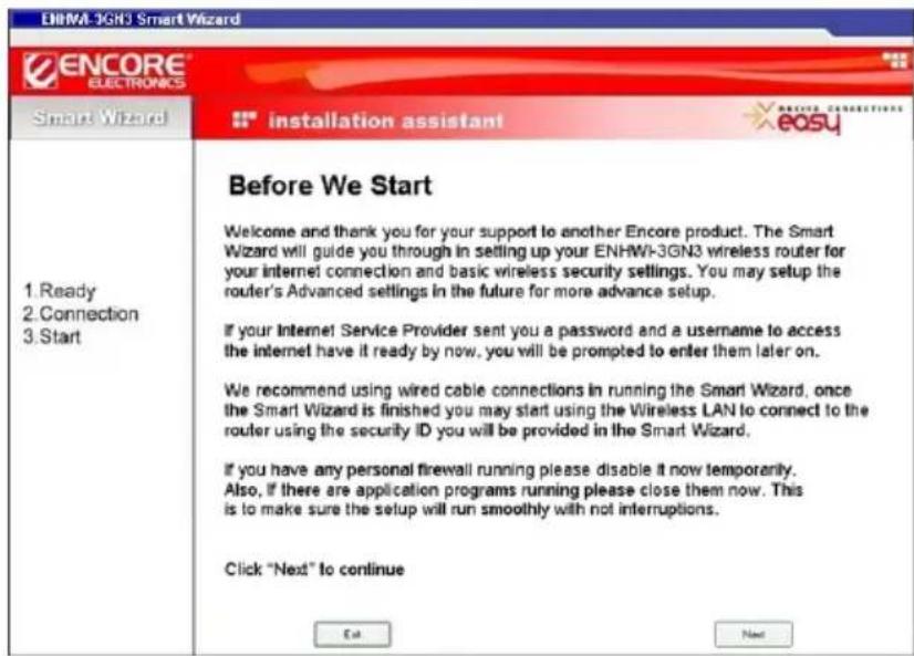
Click to proceed to the next step. Click to abort.
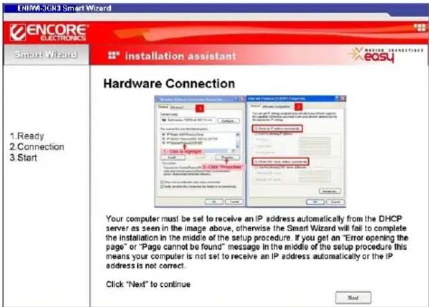
Make sure your 3G Internet, DSL modem or Cable modem broadband internet whichever is your ISP is working properly prior to this step. If not or not sure, call your Internet Service Provider and have them check and help you in check.
Check your computer's network settings as shown in the picture above. Click Next to go to the next step.

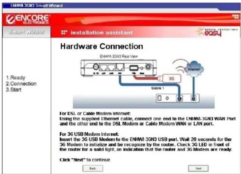
Connect your 3G modem to the ENHWI-3GN3 USB port / DSL or Cable Modem to the ENHWI-3GN3 using the supplied Ethernet cable as shown. Check power connection for modem as well as ENHWI-3GN3. Make sure the antenna is connected properly. Click Next to go to the next step.


The LED that corresponds to the ports being used should light up bright on this stage.
Click Next to continue.

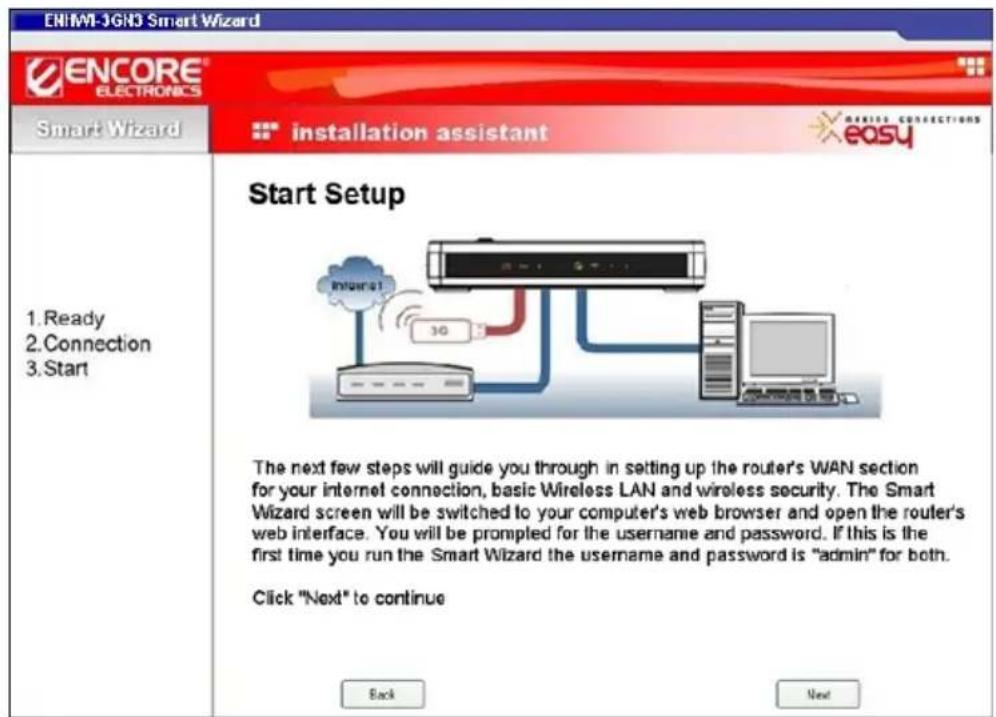
This is the last screen from the Smart Wizard. The next few setup screens will be brought up using your default web browser (Internet Explorer, FireFox, etc). You will be prompted to enter a username and password, the default is “admin” for both. You can change this default username and password to your own later on. Take time and follow and read the screen selections and instructions carefully. If you are in doubt you can contact our 24-hour tech support anytime.
Click Next to continue. You will now be redirected to the device's web interface.
Error Opening the page!
If you see this message, it is most likely that your computer is not set to receive an IP Address automatically which is required by the Smart Wizard, or your computer has a static IP address assigned which is different from the ENHWI-3GN3 IP address range. It can also be a problem from the computer, Ethernet cable being used or your default web browser. Try to restart your computer and try running the Smart Wizard again. If problem persist have a qualified computer technician or someone who is knowledgeable with computer networking check your computer and network settings.

Logging into the ENHWI-3GN3 router's User Interface for the first time:
The next few steps are still part of the Smart Wizard installation steps. You are now redirected to the router's Setup Wizard.

Enter the factory default username admin and password is also admin. Click continue.
LOGIN to
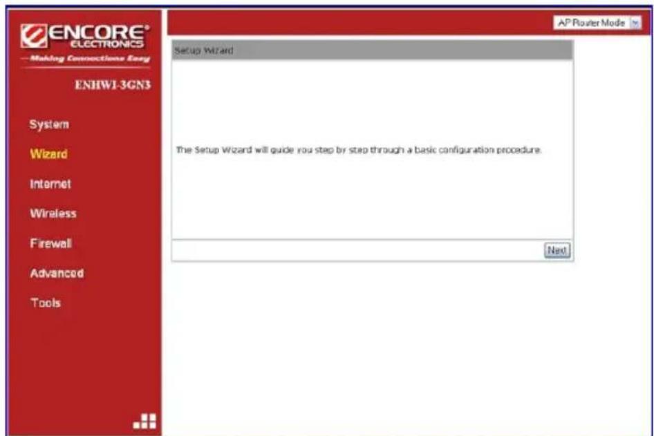
Click Next to go to the next step, the mode selection screen.

Select the mode your ENHWI-3GN3 is going to use. The Setup Wizard will skip the WAN configuration if the AP Repeater Mode is selected.
AP Router Mode – Select this mode if your intention is to use this router as an Access Point or wired and wireless route or if this is the only router you are using.
AP Repeater Mode – Select this mode if you want this router to be wireless repeater. The repeater mode means there is another router running as AP Router and this is just to repeat the signal of that AP Router to the remote computers. This will remove the DHCP and other wireless and other function. Select this only if you are well-versed with networking.
Click Next to continue. Then ENHWI-3GN3 next move is to automatically detect your "Internet" Network settings.


The Smart Wizard will detect the DHCP and PPPoE connections automatically. In the picture above it shows that the Smart Wizard detected a DHCP server. You can choose the detected service type or select “Others” to setup the WAN settings manually. Otherwise click next to accept the detected connection type. If you have not connected your router to the working DSL or Cable Modem or 3G USB Modem mentioned in the earlier instructions there will be no WAN connection type will be detected. If that is the case, you may connect the Ethernet cable again from the DSL/Cable Modem or 3G USB Modem then click the “Rescan” button. If still having problem, call your Internet Service Provider to check your subscription.

Here, you can configure the host name and MAC address of the ENHWI-3GN3. The “Clone MAC Address” button clones the MAC address of your PC and use it as the MAC address of your ENHWI-3GN3 router instead of the real MAC address of the router.
Note:
If you are unsure about this, skip this portion by clicking the "Next" button.
The Smart Wizard has finished setting up the WAN Configuration portion. Click Next to proceed to other portions.
Setting Up the Wireless LAN


Move and point your mouse pointer over to the security level blocks to select from the weakest (red block) to the strongest (green block) security level and click to select.
Block selections from the left:
| Block Color | Encryption Method | SSID Default | Authentication Type |
| Pure RED None ENCORE5FA74C None | |||
| Mostly RED WEP Open | ENCORE5FA74C | Open | |
| RED/GREEN WEP Shared Key | ENCORE5FA74C | Shared Key | |
| Mostly GREEN WPA PSK | ENCORE5FA74C | TKIP | |
| Pure GREEN WPA2 PSK | ENCORE5FA74C | AES | |
NOTE: The Default SSID shown here may be different from yours
- First Red Block – Open, no security. No wireless security is assigned. Your router is prone to unwelcomed internet users
• Second Red Block – WEP 10 or 26 bits
• Third Red/Green Block – WEP Open
• Fourth Green – WPA PSK - Fifth Green – WPA2 PSK. This is the highest level of wireless security.
Enter the name for your wireless network SSID (the default is ENCORE5FA74C), you may change it to your desired name with no spaces or leave it as is. Then enter the security key your desired (the default is 1234567890 for 10 digits and 1234567890123 for 13 digits) you may use your own or leave it as is.
The “Key” type will depend on the wireless security you have selected. If you choose WEP as the wireless security ( 2^nd or 3^rd blocks from the left) a 10-digit default key for the 2^nd block and 13-digits default key for the 3^rd block will be assigned, you can change these keys now or leave it as is.
The highest, the “Green Block” contains the WPA2 wireless security, which is the most secured and the latest wireless security. The WPA and WPA2 require a passphrase as the password. You may enter regular alpha-numeric combination as the Passphrase.
Click

to proceed to the next step.

To save configuration changes click

NOTE: After the Wireless settings are saved and the ENHWI-3GN3 is rebooted, you need to reconnect your wireless client computer using the new security settings and ID's you just change or assigned. You will need to reenter the new wireless security key to be able to connect back to the ENHWI-3GN3 wireless connections.
4. HOW TO LOGIN TO THE WEB BASED USER INTERFACE
The ENHWI-3GN3 uses a web based user interface for setting up your router's configuration. It can be access through your web browser such as Internet Explorer or Mozilla Firefox on your computer.
ENHWI-3GN3 web based user interface login procedure
- OPEN your web browser (Example: Internet Explorer, Mozilla, Netscape, etc).
- Type-in http://192.168.0.1 exactly in address field and hit the [Enter] key on your keyboard. (Or you can use the model number ENHWI-3GN3 in place of the IP address 192.168.0.1)
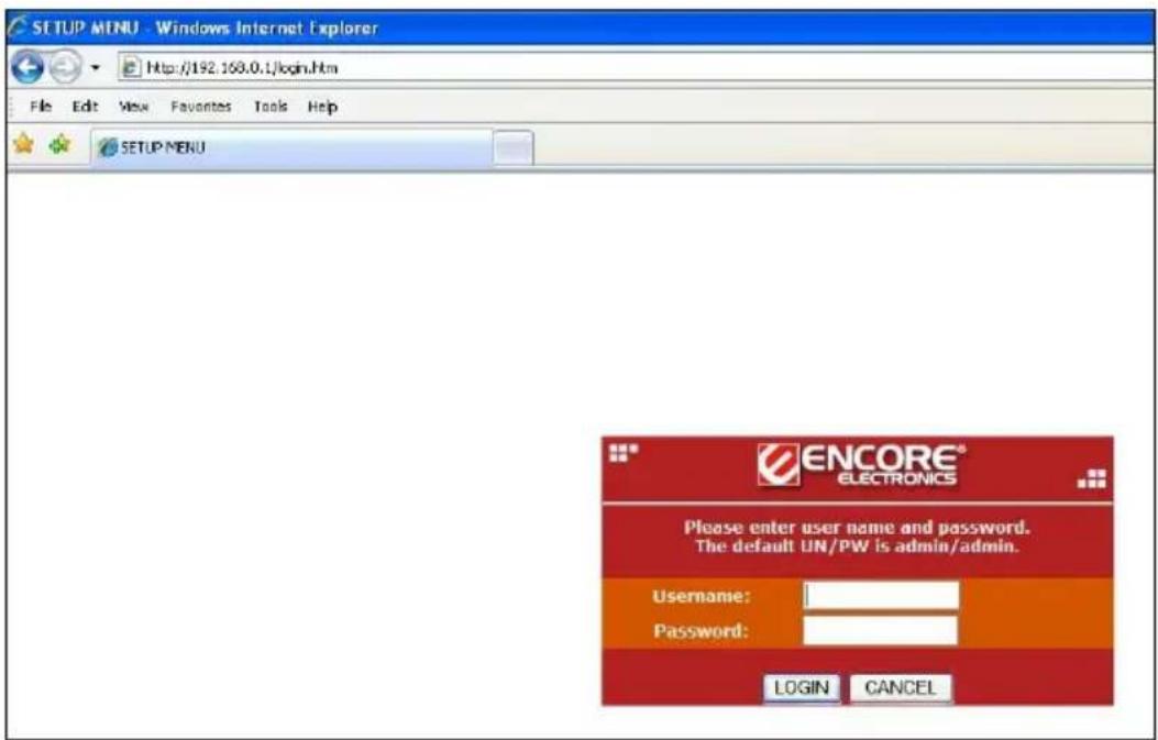
- Type-in the ENHWI-3GN3 Username and Password (the factory default is admin and admin)
- Click LOGIN to navigate into the ENHWI-3GN3 configuration home page.
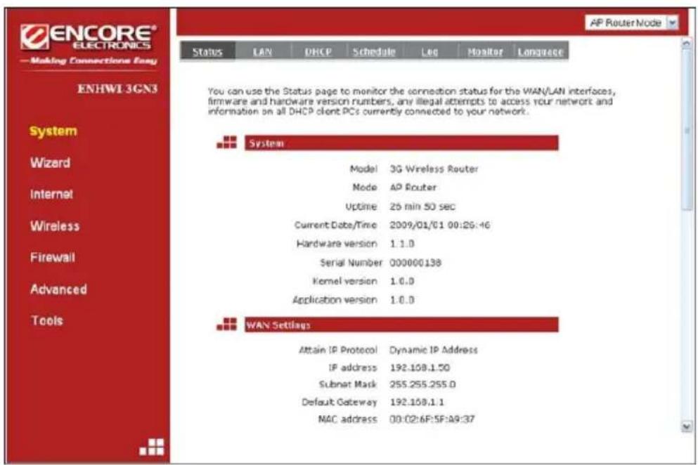
- You will see the configuration home page of the ENHWI-3GN3 as follows.
5. AP ROUTER MODE
5.1 System
Shows the Uptime, Hardware information, Serial number as well as the Firmware version information and other vital information

Status Tab
This page allows you to monitor the status of your router.

WAN Settings:
Scroll down to see more of the status information.
This section displays whether the WAN port is connected to a 3G / Cable / DSL modem. It also displays the WAN IP address, Subnet Mask, ISP Gateway, MAC address and the Primary DNS.

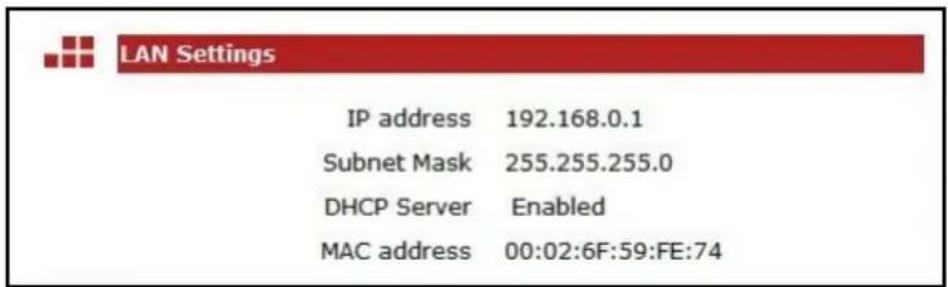
LAN Settings:
Scroll down to see this section, displays the ENHWI-3GN3 Router's LAN ports current information. It also shows whether the DHCP Server is enabled or disabled.
WLAN Settings:
Scroll down to see this section. This section displays the current WLAN configuration settings. The wireless configuration details such as the SSID, Security settings, ESSID, BSSID, Channel number and wireless clients connected info are briefly shown.

LAN Tab
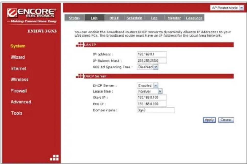
The LAN Tab is where LAN settings can be modified. If you are an entry level user, after hooking up the necessary cables, try to access the internet from your computer. If you can open a website with no problem, leave the settings as it is. If
changes were made, click the Apply button to save the changed configurations.
LAN IP
IP address: 192.168.0.1 is the router's LAN manufacturers default IP address (this will also be the "Default Gateway" IP address of your LAN clients). It can be change based on your LAN design and configurations. Typical designs don't need to change this IP address.
IP Subnet Mask: 255.255.255.0 specifies the Subnet Mask address for your LAN segment. This is based on the IP address range used.
802.1d Spanning Tree: This is disabled by default. If 802.1d Spanning Tree function is enabled, this router will use the spanning tree protocol to prevent network loops.
DHCP Server
DHCP Server: This can be enabled or disabled, "Enabled" by default.
Lease time: Time leased to all IP address by the DHCP server.
Start IP: This is the first IP address in the IP pool range in which are being assigned and leased to DHCP clients.
End IP: This is the end of the IP address pool range
Domain Name: The Domain Name for the existing or customized network.

DHCP Tab
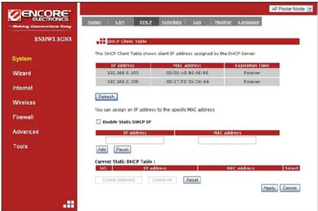
This is where to view the current LAN clients that have assigned or leased an IP address by the DHCP server. This screen also shows all the DHCP clients that are currently connected to your network. The table shows the assigned or leased IP address, MAC address and the lease expiration data for each DHCP clients. Use the
You can click to put a check mark on “Enable Static DHCP IP”. It is possible to add more static DHCP IP addresses. They are listed in the table “Current Static DHCP Table”. IP address can be deleted if wanted to.
Click the

Schedule Tab
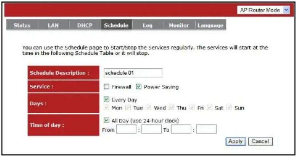
This page allows users to set up a scheduled function for the Firewall and Power Saving features of the ENHWI-3GN3 router.

Edit the scheduled function to allow configuration for firewall or power savings services. Fill in the schedule and select type of service you desired. Click

The “Schedule” table screen lists the pre-scheduled services. Select any of the schedules by using the check box located on the right side of each line to edit or Delete selected schedule line.
Event Log Tab
On this “Event Log” screen, it displays all events and events information occurred after the start-up. Scroll down to see more. The Event Log can be saved to the local file-storage device such as hard disc drive by using the
![ENCORE® ELECTRONICS Making Connections Emg ENHW1-2AN3 System Wizard Internet Wireless Firewall Status IAN DHCP Schedule Los Routier Language View the system operation information. day 1 18:17:12 [SYSTEM]: DHCP Server, sending ACK of 192.168.0.100 day 1 18:17:12 [SYSTEM]: DHCP Server, sending OFFER of 191.168.0.100 day 1 00:00:00 [SYSTEM]: WAN, No PHY Link day 1 00:00:00 [SYSTEM]: WAN, start DHCP mode day 1 00:00:00* [SYSTEM]: WAN, stop DHCP mode Save Clear Refresh AP Router Mode](/content/2026/05/1066818/images/2fa9a9123de642b9f202e5246a85f27085c2fc231422a8ee22ad7597fe68c745.jpg)
Monitor Tab
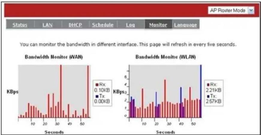
This screen shows the histogram of the network connection on WAN, LAN & WLAN. Auto refresh keeps information updated frequently.
bar
| Interface | Rx (KBps) | Tx (KBps) | | :--- | :--- | :--- | | WAN | 0.10 | 0.00 | | WLAN | 2.21 | 2.57 |Language Tab
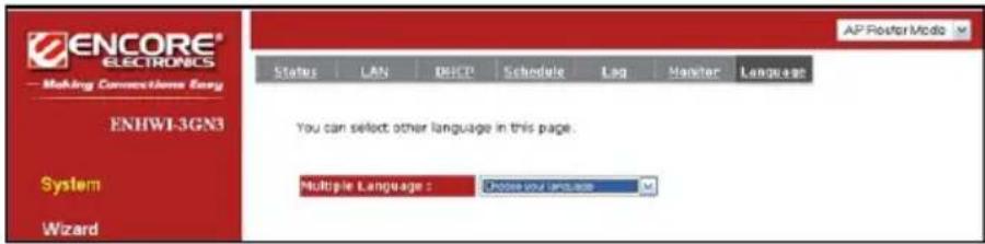
This is where you select preferred language.
5.2 Wizard
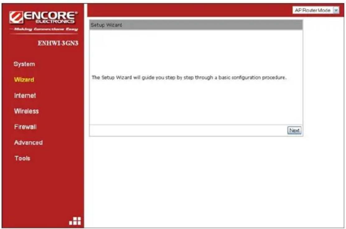
Click Wizard to configure the basic functionalities of the ENHWI-3GN3 Router. A popup Setup Wizard Window will be displayed. If the popup window for Setup Wizard failed to appear check your Popup Settings and make sure popup is allowed at least temporarily for this purpose. Before you continue, check all the needed cables if they are properly hooked up. Check your 3G, DSL or Cable Modem if working properly and is connected to your ISP and then click
5.3 Internet
NOTE:
ENHWI-3GN3 supports both 3G and ADSL/Cable Modem for Internet access.
Please note that the 3G network by default is the preferred Internet option.
Therefore, in case you have both 3G and ADSL/Cable Modem internet
connection, the ENHWI-3GN3 will automatically use 3G for Internet access
and disable the ADSL/Cable Modem connection. Inserting a 3G USB Modem
adapter the ENHWI-3GN3 will turn off the ADSL/Cable Modem connection
immediately.
The 3G USB Modem adapter may take more than 20 seconds to initiate and
ties up to ENHWI-3GN3. Wait and check the 3G LED in the front panel. Once
the LED stays at green light, the 3G is ready.

Status Tab
This page shows the current Internet connection type and status

Dynamic IP Tab
Use the MAC address when registering for the Internet service, and do not change it unless required by your ISP. If your ISP use the MAC address of the Ethernet card as an identifier, connect only the PC with the registered MAC address to the broadband router and click the

Host Name: This is optional.
MAC address: The default value is set to the WAN's physical address or MAC of the broadband router.
Static IP Tab
If your ISP Provider has assigned a fixed public IP address for you to use, enter the assigned IP address, Subnet Mask, Default Gateway IP address, Primary and Secondary DNS (if available) of your ISP provider.


Point-to-Point Protocol over Ethernet (PPPoE) Tab

NOTE: Most of the data filled here will be supplied by your Internet Service Provider. Call your ISP if you're in doubt.
Login / Password: Enter the PPPoE username and password assigned by your ISP or internet service provider.
Service Name: This is optional.
Maximum Transmission Unit (MTU): This is the maximum size of the packets.
Type:
Keep Connection - will stay connected to the Internet
Automatic Connection - automatically connects to the Internet when an application needs it, and drops the connection after the designated idle time period.
Manual Connection – manually connect and disconnect to the internet by the user Idle Timeout (available only under Automatic Connection): This is a maximum period of time for which the Internet connection is maintained during inactivity. If the application is inactive for certain time designated here the internet connection will be automatically dropped.
Point-to-Point Tunneling Protocol (PPTP) Tab
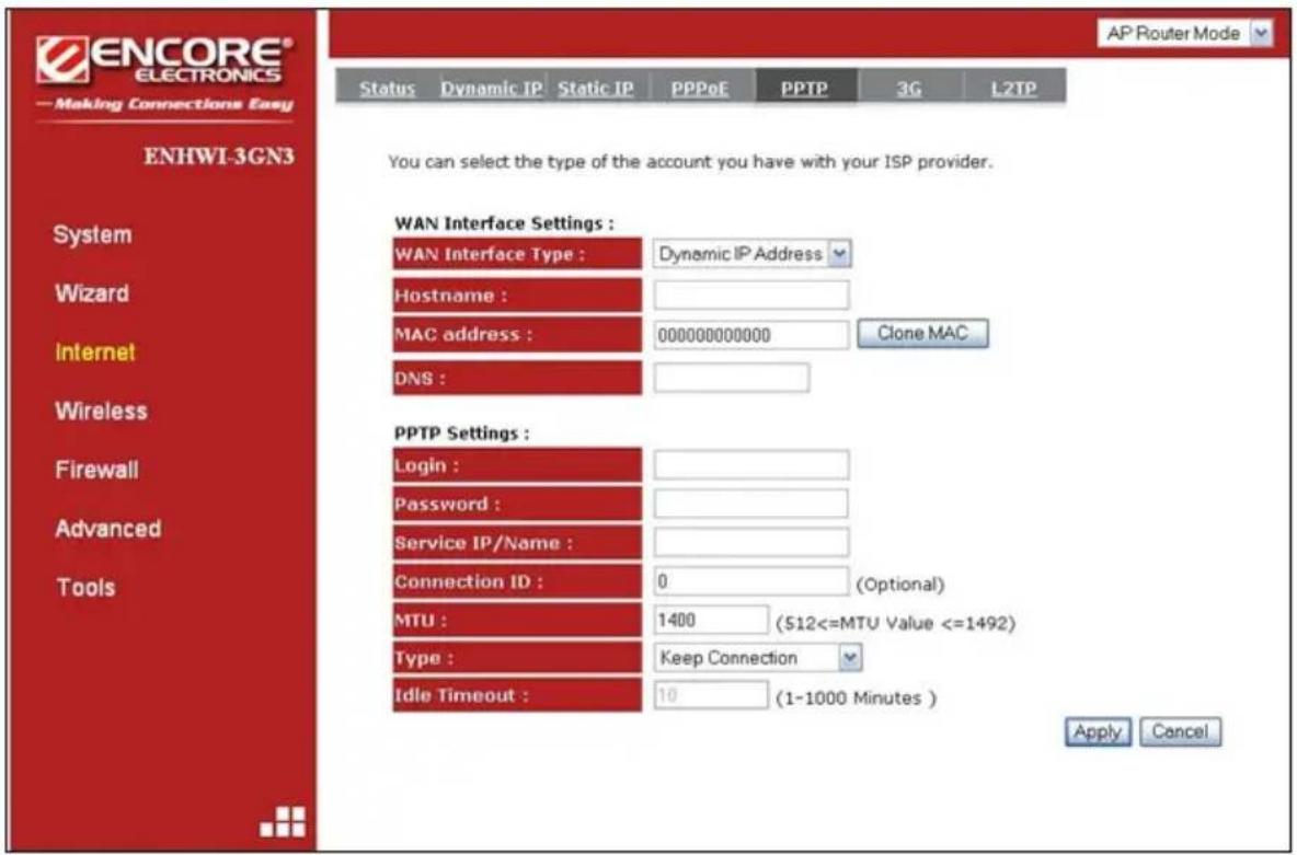
NOTE: Most of the data to be filled here will be supplied by your Internet Service Provider. Call your ISP if you're in doubt
PPTP allows the secure connection over the Internet by simply dialing in to a local point provided by your ISP provider. The image screen allows client PCs to establish a normal PPTP session and provides hassle-free configuration of the PPTP client on each client PC. Click
3G Tab

Note: You may need the 3G account detail and configuration from your local 3G ISP
Pin code: Enter the Pin Code here (provided by your 3G ISP)
APN Code: Enter APN Code here (provided by your 3G ISP)
Dial Number: Enter phone number here (provided by your 3G ISP)
User Name: Enter 3G network account /username (provided by your 3G ISP)
Password: Enter 3G network account password (provided by your 3G ISP)
Type:
- Keep Connection: Keep connection with or without the presence of traffic.
• Automatic Connection: Connect when traffic is detected. - Manual Connection: Connect only on user's demand (see status)
Idle Timeout: Disconnect from 3G network if there's no traffic in the specified timeout period.
Layer 2 Tunneling Protocol (L2TP) Tab
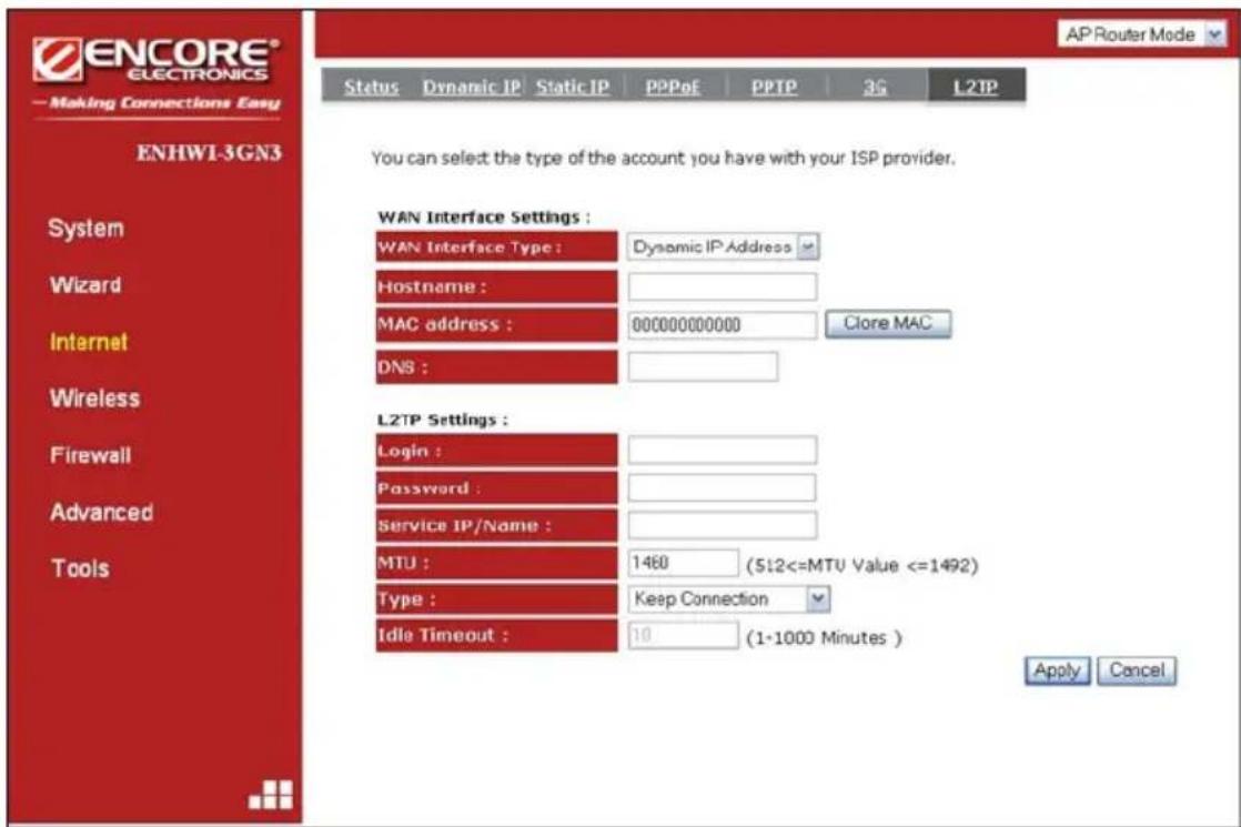
NOTE: Most of the data to be filled here will be supplied by your Internet Service Provider. Call your ISP if you're in doubt
WAN Interface Settings:
WAN Interface Type:
- Dynamic IP Address – Use the DHCP client function to retrieve WAN port IP address, which will be used to establish the L2TP tunnel. The router's L2TP tunnel address will be assigned after tunnel is established, which will be different from the WAN IP address it gets earlier.
- Hostname: This is optional. If your ISP requires you to put a hostname, you may enter it here.
- MAC address : Optional. This address will overwrite WAN port default MAC address. If your ISP provides this MAC address, enter it here. You can also click "Clone MAC" button to clone your PC's MAC address to overwrite WAN port default MAC address.
- DNS : Optional. If your ISP doesn't provide you with a DNS server address automatically through DHCP, enter a DNS server IP address here, if "Service IP/Name" field is domain name in "L2TP Settings".
- Static IP Address – Manually configure WAN port IP address, contents of this are:
o My IP Address: This is the WAN port IP address provided by your ISP to establish the L2TP tunnel.
o My Subnet Mask : This is the WAN port Subnet Mask provided by your ISP to establish the L2TP tunnel.
- Gateway IP Address: This is the WAN port Gateway IP address provided by your ISP to establish L2TP tunnel.
- DNS: This is optional. This is the WAN port DNS address provided by your ISP to resolve the website IP Address into the domain or URL name during establishing L2TP tunnel if you use domain name in "Service IP/Name" instead of IP address.
L2TP Settings:
- Login : Enter the L2TP username assigned by your ISP Provider.
- Password : Enter the L2TP password assigned by your ISP Provider.
■ Service IP/Name : Enter the L2TP server IP address or domain name.
- MTU: What would you select would be the maximum size of packets. Keep it in default if you are not familiar with this setting.
- Type :
- Keep Connection - stay connected to the Internet - Automatic Connection - automatically connects to the Internet when an application needs it, and drops the connection after the designated idle time period.
- Manual Connection – manually connect and disconnect to the internet by the user
Idle Timeout : This function is available only if Automatic Connection is selected under "Type". This is a maximum period of time for which the Internet connection is maintained during inactivity. If the application is inactive for certain time designated here the internet connection will be automatically dropped.
5.4 Wireless Settings
> Basic Tab
In Basic tab page, you can set wireless Radio Disable or Enable, WDS, AP or Repeater Mode, Band selections, Number of SSID's up to 4, Enable / Disable Auto Channel and Channel number.
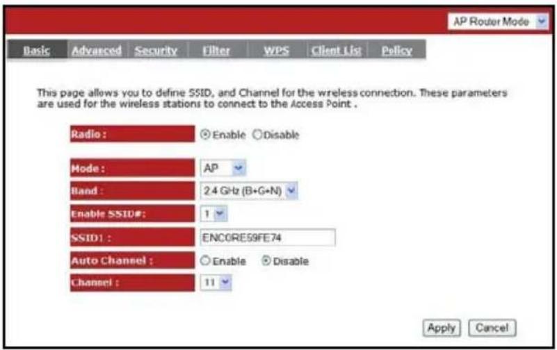
Radio: You can turn on/off wireless radio. If wireless Radio is turned off, the ENHWI-3GN3 will not take wireless connections.
Mode: Three operation modes for selections, the AP router and AP router with WDS. If you choose AP Router Mode, there will be two selections under it, the AP or WDS function in the drop-down menu.
Band: You can select the wireless standards running on your network environment such as the following:
2.4 GHz(B): If all your clients are using 802.11b
2.4 GHz(N): If all your clients are using 802.11n
2.4 GHz(B+G): If both 802.11b or a 802.11g
2.4 GHz(G): If all your clients are using 802.11g
2.4 GHz(B+G+N): If your clients are mixed using 802.11b, 802.11g, or 802.11n
Enable SSID: ENHWI-3GN3 supports up to 4 SSID's. Use the down arrow to select the number of SSID you wanted to have in your wireless LAN. Once established you can set the security policy settings for each. See "Policy" section for more details.
SSID1 to SSID4: Whatever is entered into the SSID block that will be the name of your wireless network. It is recommended to use a unique name to identify your wireless device in the WLAN such as “Guests”, “Home”, etc. This is case sensitive and up to 32 printable characters.
Auto Channel: Disabled by default. If Enabled, will automatically search all channels and automatically change to the clearest channel detected. Different items are visible below the Auto Channel.
Channel: Channel 11 by default. This is visible only when the Auto Channel is disabled. You can enter your preferred channel number here for the ENHWI-3GN3 wireless LAN.
Check Channel Time: This menu is visible only when the Auto Channel is enabled. Selections are from One Hour to One Week. This is the duration of when will the ENHWI-3GN3 check for and use the clearest channel in the area automatically.
WDS Mode
The Wireless Distribution System is a way of interconnecting wireless routers and allow an extended wireless network coverage using multiple wireless routers without the use of a wired backbone. Each WDS AP requires the same channel and encryption type to work. Setting up a WDS requires an in-depth knowledge in computer networking. If you are not familiar with this setting consult a PC network engineer.

MAC address 1\~4:
Enter the MAC address of the neighboring APs that participates in the WDS. A maximum of 4 devices are allowed.
Set Security:
WDS Security depends on your AP security settings. Note: It does not support mixed mode such as WPA-PSK/WPA2-PSK Mixed mode.
Advanced Tab
On this tab you can set the advanced wireless settings. If you're in doubt what to enter or use here, leave these settings as it is. This is for advance users only. Wrong parameters can make the router un-operational.

Fragment Threshold:
Default value is 2346. Specifies the maximum size of a packet during the fragmentation of data to be transmitted. If you set this value too low, it will result in a bad performance.
RTS Threshold:
Default value is 2347. When the packet size is smaller than the RTS threshold, the wireless router will not use the RTS/CTS mechanism to send this packet.
Beacon Interval:
Default value is 100. This is the interval of time that this wireless router broadcasts a beacon. A Beacon is used to synchronize the wireless network.
DTIM Period:
Default value is 1. Enter a value between 1 and 255 for the Delivery Traffic Indication Message (DTIM). A DTIM is a countdown informing clients of the next window for listening to broadcast and multicast messages.
Data Rate:
The “Data Rate” is the rate that this access point uses to transmit data packets. The access point will use the highest possible selected transmission rate to transmit the data packets.
N Data Rate:
The “Data Rate” is the rate that this access point uses to transmit data packets for N compliant wireless nodes. Highest to lowest data rate can be fixed.
Channel Bandwidth:
This is the range of frequencies that will be used. Select “Auto 20/40 MHz” if you have wireless client using 802.11n to connect to this router.
Preamble Type:
The “Long Preamble” can provide better wireless LAN compatibility while the “Short Preamble” can provide better wireless LAN performance.
CTS Protection:
It is recommended to enable the protection mechanism. This mechanism can decrease the rate of data collision between 802.11b and 802.11g wireless stations. When the protection mode is enabled, the throughput of the AP will be a lower due to an increase of data frame transmission.
TX Power:
10% to 100%. Default value is 100%.
Security Tab
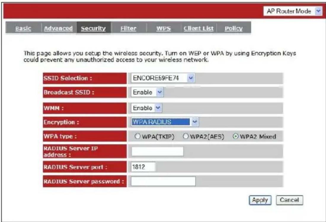
ENHWI-3GN3 provides complete wireless LAN security types. Selections are WEP, IEEE 802.1x, IEEE 802.1x with WEP, WPA with pre-shared key or PSK and WPA with RADIUS. With these wireless securities, unauthorized access can be prevented. Make sure all other wireless stations use the same security type, and were setup with the same security key.

ESSID Selection:
The ENHWI-3GN3 router supports multiple ESSID, you can enter your desired wireless ESSID here.
Broadcast ESSID:
If you enabled “Broadcast ESSID”, every wireless station located within the coverage of this Router can see this ESSID. If you are building a public wireless network, enabling this feature is recommended. Disabling “Broadcast ESSID” can provide better security.
WMM:
Wi-Fi Multi Media, if enabled, supports QoS to dedicate line and other resource for better audio, video and voice streaming to a particular station and applications.
Encryption:
If set to Disable, the router will have no protection against uninvited wireless guests, your LAN will be prone to hackers. It is highly recommended to Enable this function and set your own wireless security.
Enable 802.1x Authentication
IEEE 802.1x is an authentication protocol using RADIUS server. When this is Enabled, every LAN user must use an account to login to this Access Point before accessing the wireless LAN. The authentication is processed by a RADIUS server. This mode only authenticates users by IEEE 802.1x, but it does not encrypt the data during communication.

WEP Encryption
When you select 64-bit or 128-bit WEP key, you have to enter WEP keys to encrypt data. You can generate the key by yourself. You can enter up to four WEP keys and select one of them as a default key. The AP can receive any packet encrypted by one of the four keys.

Authentication Type:
There are two authentication types: "Open System" and "Shared Key". Both AP and wireless client must be configured with the same authentication type.
Key Length:
You can select the WEP key length for encryption, 64-bit or 128-bit. The larger the key will be the higher level of security is used, but the throughput will be lower.
Key Type: You may select ASCII Characters (alphanumeric format) or Hexadecimal Digits (in the "A-F", "a-f" and "0-9" range) to be the WEP Key.
Default Key: It's the key used to encrypt data.
Key1 - Key4: The WEP keys are used to encrypt data transmitted in the wireless network. Use the following rules to setup a WEP key on the device.
64-bit WEP: input 10-digits Hex values (in the "A-F", "a-f" and "0-9" range) or 5-digit ASCII character as the encryption keys.
128-bit WEP: input 26-digit Hex values (in the "A-F", "a-f" and "0-9" range) or 13-digit ASCII characters as the encryption keys.
Click
WPA Pre-Shared Key Encryption
Wi-Fi Protected Access (WPA) is an advanced security standard. You can use a pre-shared key to authenticate wireless stations and encrypt data during communication. It uses TKIP or CCMP (AES) to change the encryption key frequently. The encryption key is not easy to be cracked by hackers. This is the best security available.

WPA-RADIUS Encryption
Wi-Fi Protected Access (WPA) is an advanced security standard. You can use an external RADIUS server to authenticate wireless stations and provide the session key to encrypt data during communication. It uses TKIP or CCMP (AES) to change the encryption key frequently. Press
MAC Address Filtering Table
This wireless router supports MAC Address Control, which prevents unauthorized clients from accessing your wireless network.
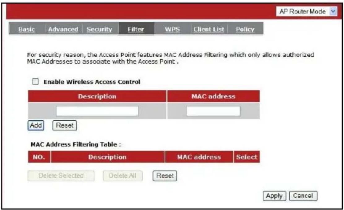
Enable wireless access control: Enable the wireless access control function
Adding an address into the list
Enter the "MAC Address" and "Description" of the wireless station to be added and then click
Remove an address from the list
If you want to remove a MAC address from the "MAC Address Filtering Table", select the MAC address that you want to remove in the list and then click "Delete Selected". If you want to remove all the MAC addresses from the list, just click the
Click
WPS Tab - Push Button Wireless Connection
Push Button Wireless Connection is the simplest way to establish a connection between the wireless clients and the wireless router. You don't have to select the encryption mode and fill in a long encryption passphrase every time when you try to setup a wireless connection. You only need to press a button on both wireless client and wireless router, and the WPS will do the rest for you.
The wireless router supports two types of Push Button Wireless Connection, the Push Button and PIN code. If you want to use the Push Button, you have to push a specific button on the wireless client or in the utility of the wireless client to start the Push Button Wireless Connection mode, and switch the wireless router to Push Button Wireless Connection mode. You can simply push the push button of the wireless router, or click the 'Start to Process' button in the web configuration interface. If you want to use the PIN code, you have to know the PIN code of the wireless client and switch it to Push Button Wireless Connection mode, then fill-in the PIN code of the wireless client through the web configuration interface of the wireless router.

WPS: (Push Button Wireless Connection)
Check the box to enable WPS function and uncheck it to disable the WPS function.
WPS Current Status:
If the wireless security (encryption) function of this wireless router is properly set, you'll see a 'Configured' message here. Otherwise, you'll see 'UnConfigured'. Click the "Release Configuration" can clear the security settings of the 1st SSID.
Self Pin Code:
This is the Push Button Wireless Connection PIN code of the wireless router. You may need this information when connecting to other WPS-enabled wireless devices.
SSID:
This is the network broadcast name (SSID) of the router.
Authentication Mode:
It shows the active authentication mode for the wireless connection.
Passphrase Key:
It shows the passphrase key that is randomly generated by the wireless router during the WPS process. You may need this information when using a device which doesn't support WPS.
Interface:
If device is set to repeater mode, you can choose “Client” interface to connect with other AP by using WPS, otherwise you may choose “AP” interface to do WPS with other clients.
WPS via Push Button:
Press the button to start the WPS process. The router will wait for the WPS request from the wireless devices within 2 minutes.
WPS via PIN:
You can fill-in the PIN code of the wireless device and press the button to start the WPS process. The router will wait for the WPS request from the wireless device within 2 minutes.
Client List Tab
WLAN Client Table shows the Wireless clients associated to this Wireless Router.

Policy Tab
The Broadband router can allow you to set up the Wireless Access Policy up to 4 SSID's.

5.5 Firewall Settings
The Broadband router provides extensive firewall protection by restricting connection parameters, thus limiting the risk of hacker attacks, and defending against a wide array of common Internet attacks. However, for applications that require unrestricted access to the Internet, you can configure a specific client/server as a Demilitarized Zone (DMZ).
Enable Tab
Enables or Disables the Firewall

Advanced Tab
You can allow the VPN packets to pass through this Broadband router.

Demilitarized Zone (DMZ) Tab
If you have a client PC that cannot run an Internet application (e.g. Games) properly behind the NAT firewall, then you can open up the firewall restrictions to unrestricted two-way Internet access by defining a DMZ Host. The DMZ function allows you to re-direct all packets going to your WAN port IP address to a particular IP address in your LAN. The difference between the virtual server and the DMZ function is that the virtual server re-directs a particular service/Internet application (e.g. FTP, websites) to a particular LAN client/server, whereas DMZ re-directs all packets (regardless of services) from your WAN IP address to a particular LAN client/server.

Enable DMZ: Enable / Disable DMZ
LAN IP Address: Fill-in the IP address of a particular host in your LAN Network or select a PC from the list on the right that will receive all the packets originally from the WAN port/Public IP address.
Click
▶ Denial of Service (DoS) Tab
The Broadband router's firewall can block common hacker attacks, including Denial of Service, Ping of Death, Port Scan and Sync Flood. If Internet attacks occur the router can log the events.

Flood: Protects the router from Sync Flood attack.
MAC Filter Tab
If you want to restrict users from accessing certain Internet applications / services (e.g. Internet websites, email, FTP etc.), and then this is the place to set that configuration. MAC Filter allows users to define the traffic type permitted in your LAN. You can control which PC client can have access to these services.

Enable MAC Filtering: Check to enable or disable MAC Filtering.
Deny: If you select "Deny" then all clients will be allowed to access Internet except the clients in the list below.
Allow: If you select "Allow" then all clients will be denied to access Internet except the PCs in the list below.
Add PC MAC Address
Fill in "LAN MAC Address" and
Remove PC MAC Address
If you want to remove some PC from the "MAC Filtering Table", select the PC you want to remove in the table and then click
Click
IP Filter Tab
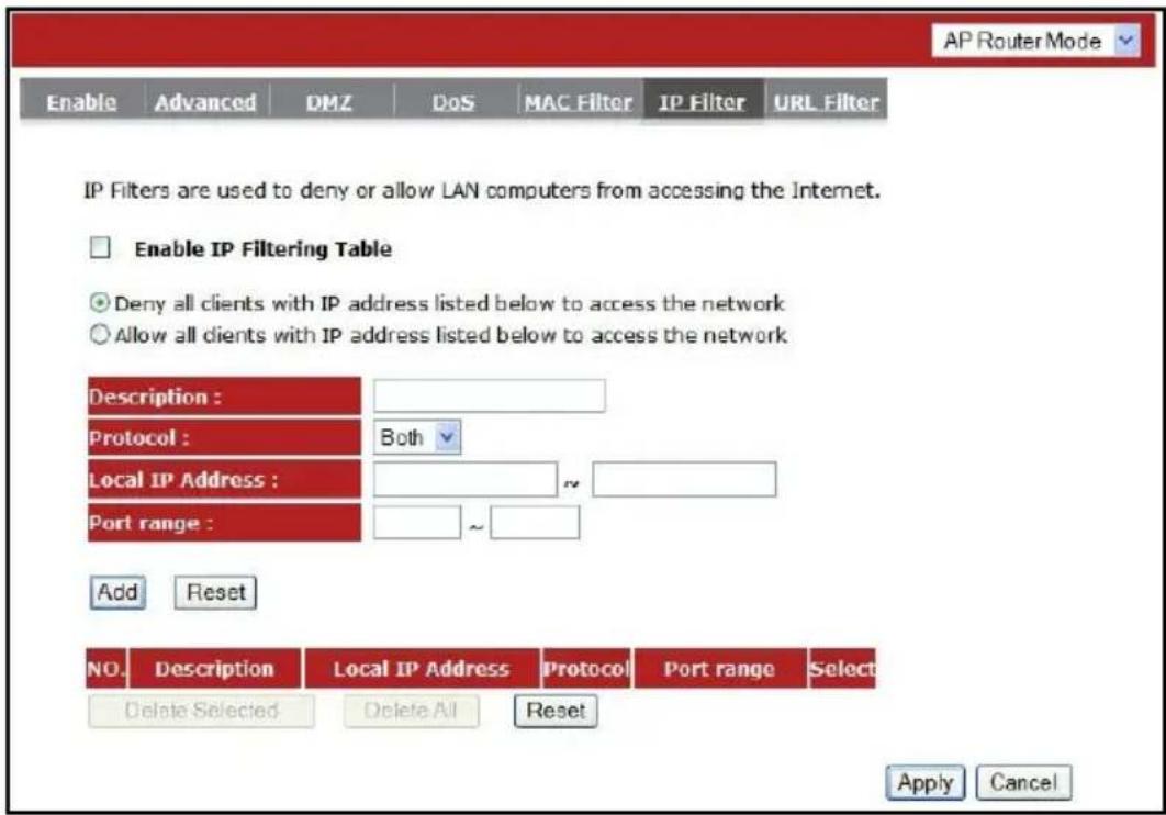
Enable IP Filtering: Check to enable or uncheck to disable IP Filtering.
Deny: If you select "Deny" then all clients will be allowed to access Internet except for the clients in the list below.
Allow: If you select "Allow" then all clients will be denied to access Internet except for the PCs in the list below.
Add PC IP Address
You can click
Remove PC IP Address
If you want to remove some PC IP from the
Click
URL Filter Tab
You can block access to some Web sites from particular PCs by entering a full URL address or just keywords of the Web site.

Enable URL Blocking: Enable or disable URL Blocking
Add a URL Keyword
Fill-in the "URL/Keyword" field with your url / keyword, and then click
Remove URL Keyword
If you want to remove some URL keywords from the "Current URL Blocking Table", select the URL keyword you want to remove in the table and then click
Click
5.6 Advanced Settings
Network Address Translation (NAT) Tab
Network Address Translation (NAT) allows multiple users at your local LAN site to access the Internet using a single Public IP Address or multiple Public IP Addresses. NAT provides Firewall protection from hacker attacks and has the flexibility to allow you to map Private IP Addresses to Public IP Addresses for key services such as Websites and FTP. Select Disable to disable the NAT function.

Port Mapping Tab
Port Mapping allows you to re-direct a particular range of service port numbers (from the Internet / WAN Port) to a particular LAN IP address. It helps you to host servers behind the router NAT firewall.

Enable Port Mapping: Enable or disable port mapping function.
Description: description of this setting.
Local IP: This is the local IP of the server behind the NAT firewall.
Protocol: This is the protocol type to be forwarded. You can choose to forward "TCP" or "UDP" packets only, or select "BOTH" to forward both "TCP" and "UDP" packets.
Port Range: The range of ports to be forward to the private IP.
Add Port Mapping
Fill in the "Local IP", "Protocol", "Port Range" and "Description" of the setting to be added and then click "Add". Then this Port Mapping setting will be added into the "Current Port Mapping Table" below. If you find any typo before adding it and want to retype again, just click
Remove Port Mapping
If you want to remove a Port Mapping setting from the "Current Port Mapping Table", select the Port Mapping setting that you want to remove in the table and then click D
Click
Port Forwarding Tab (Virtual Server)
Use the Port Forwarding (Virtual Server) function when you want different servers/clients in your LAN to handle different service/Internet application type (e.g. Email, FTP, Web server etc.) from the Internet. Computers use numbers called port numbers to recognize a particular service/Internet application type. The Virtual Server allows you to re-direct a particular service port number (from the Internet/WAN Port) to a particular LAN private IP address (See Glossary for an explanation on Port number).

Enable Port Forwarding: Enable or disable Port Forwarding.
Description: The description of this setting.
Local IP / Local Port: This is the LAN Client/Host IP address and Port number that the Public Port number packet will be sent to.
Protocol: Select the port number protocol type (TCP, UDP or both). If you are unsure, then leave it to the default "both" setting. Public Port enters the service (service/Internet application) port number from the Internet that will be re-directed to the above Private IP address host in your LAN Network.
Public Port: Port number will be changed to Local Port when the packet enters your LAN Network.
Add Port Forwarding
Fill in the "Description", "Local IP", "Local Port", "Protocol" and "Public Port" of the setting to be added and then click
Remove Port Forwarding
If you want to remove Port Forwarding settings from the "Current Port Forwarding Table", select the Port Forwarding settings you want to remove in the table and then click "Delete Selected". If you want to remove all Port Forwarding settings from the table, just click the
Click
Port Triggering Tab (Special Applications)
Some applications require multiple connections, such as Internet games, video Conferencing, Internet telephony and others. In this section you can configure the router to support multiple connections for these types of applications.

Enable Trigger Port: Enable or disable the Port Trigger function.
Trigger Port: This is the outgoing (Outbound) range of port numbers for this particular application.
Trigger Type: Select whether the outbound port protocol is "TCP", "UDP" or "BOTH".
Public Port: Enter the In-coming (Inbound) port or port range for this type of application (e.g. 2300-2400, 47624)
Public Type: Select the Inbound port protocol type: "TCP", "UDP" or "BOTH"
Popular Applications: This section lists the more popular applications that require multiple connections. Select an application from the Popular Applications selection. Once you have selected an application, select a location (1-5) in the “Add” selection box and then click the
Add Port Triggering
Fill in the "Trigger Port", "Trigger Type", "Public Port", "Public Type", "Public Port" and "Description" of the setting to be added and then Click
Remove Port Triggering
If you want to remove Special Application settings from the "Current Trigger-Port Table", select the Port Triggering settings you want to remove in the table and then click
Application Layer Gateway (ALG) Tab
You can select applications that need ALG support. The router will let the selected application to correctly pass through the NAT gateway.
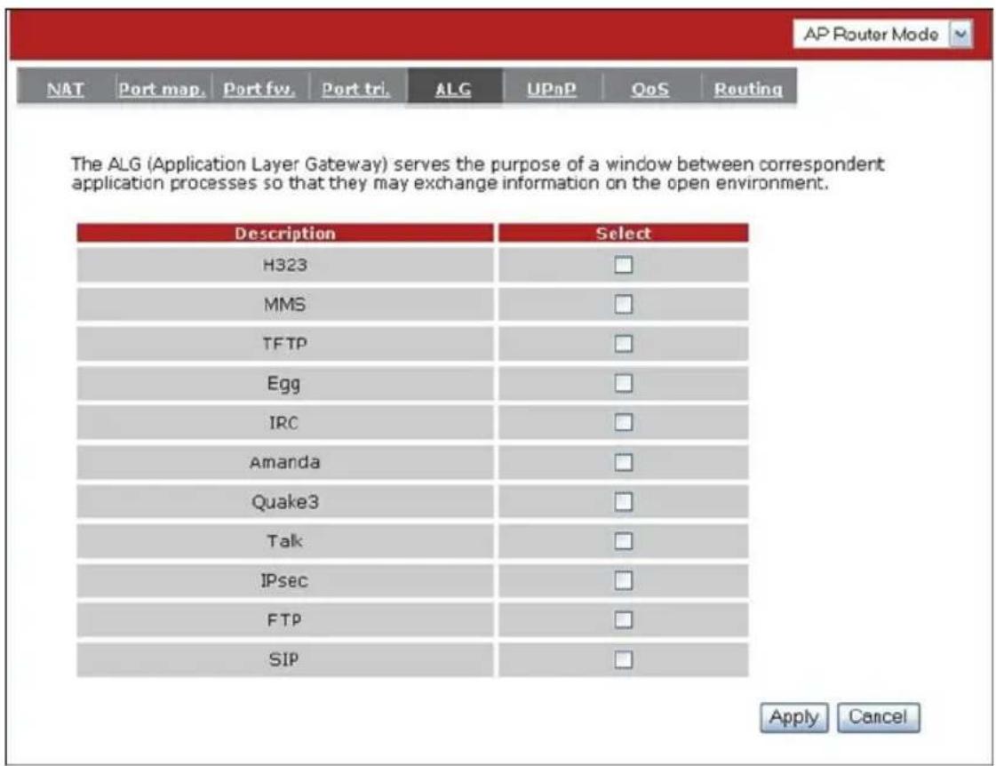
UPNP Tab
With UPnP, all PCs in you Intranet will discover this router automatically. So, you don't have to configure your PC and it can easily access the Internet through this router.

Enable / Disable UPnP: You can enable or Disable the UPnP feature here. After you enabled the UPnP feature, all client systems that support UPnP, like Windows XP, can discover this router automatically and access the Internet through this router without having to configure anything. The NAT Traversal function provided by UPnP can let applications that support UPnP connect to the internet without having to configure the virtual server sections.
Quality of Service (QoS) Tab
QoS lets you classify Internet application traffic by source/destination IP address and port number. You can assign priority for each type of application and reserve bandwidth for it. The packets of applications with higher priority will always go first. Lower priority applications will get bandwidth after higher priority applications get enough bandwidth. This can let you have a better experience in using critical real time services like Internet phone, video conference, etc. All the applications not specified by you are classified as “Others”.
Priority Queue
You can enter packets of specific protocols in High or Low Queue. The packets in High Queue will be a high priority and will be processed first.

Unlimited Priority Queue: The LAN IP address in this field is not subject to the QoS limitations.
High/Low Priority Queue: Sets protocols and port number to High/Low QoS priotiy Queue.
Bandwidth Allocation:
This is where to set the bandwidth allocation of specific port or port range, bound for specific IP address and set for upload or download speed in bit per second.
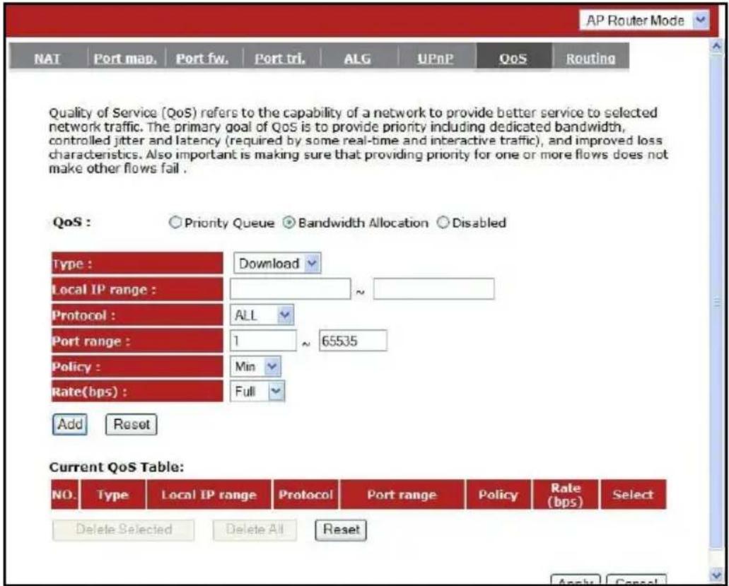
Type: Specify the direction of packets. Upload / Download or both.
IP range: Specify the IP address range. You could also fill one IP address
Protocol: Specify the packet type. The default ALL will put all packets in the QoS priority Queue.
Port range: Specify the Port range. You could also fill one Port.
Policy: Specify the policy of QoS, Min option will reserve the selected data rate in QoS queue. Max option will limit the selected data rate in QoS queue.
Rate: The data rate of QoS queue.
Disable QoS

Disabled: This turn off QoS Service.
Routing Tab
You can set to Enable Static Routing to let the router forward packets using your routing policy.
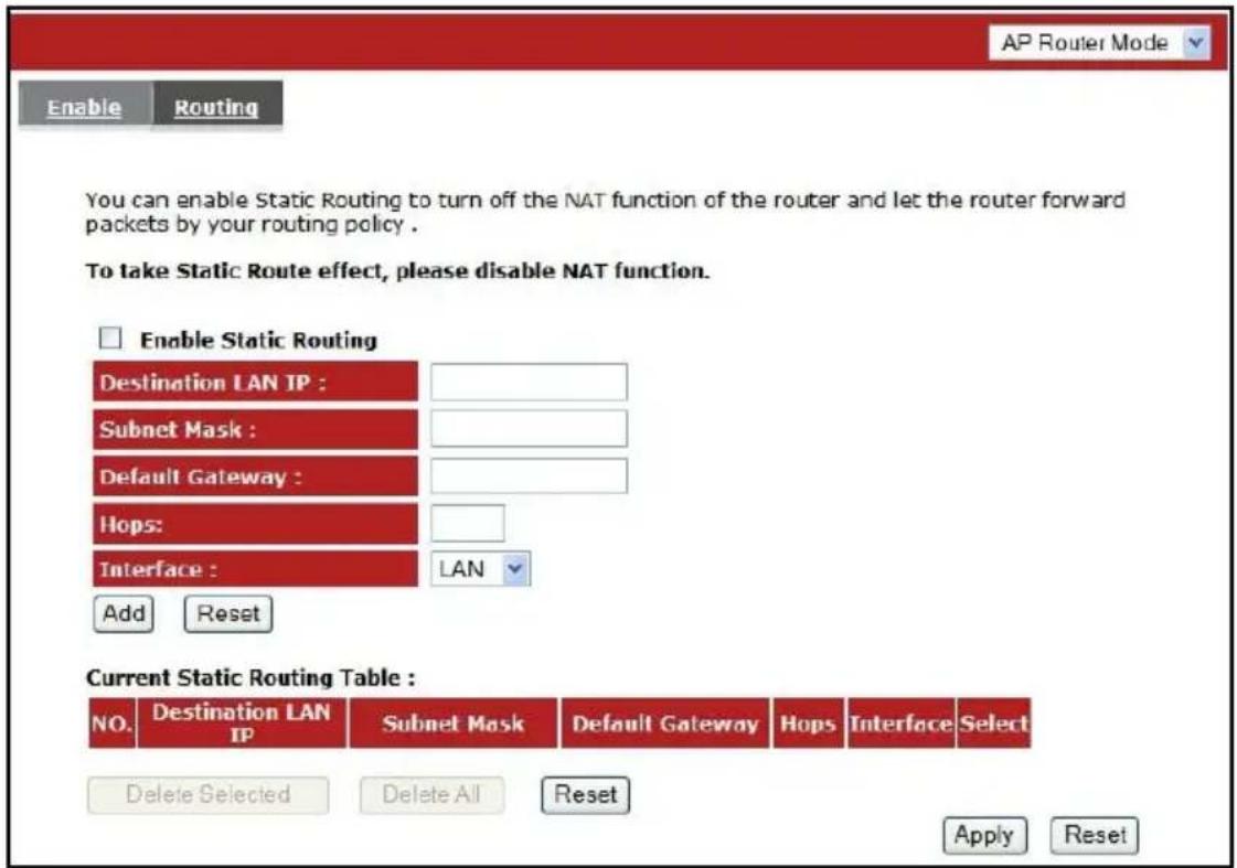
Destination LAN IP: Specify the destination LAN IP address of static routing rule.
Subnet Mask: Specify the Subnet Mask of static routing rule.
Default Gateway: Specify the default gateway of static routing rule.
Hops: Specify the Max Hops number of static routing rule.
Interface: Specify the Interface of static routing rule.
5.7 Tools Settings
Admin Tab
You can change the password required to log into the broadband router's system web-based management. By default, the password is admin. Passwords can contain 0 to 12 alphanumeric characters, and are case sensitive.
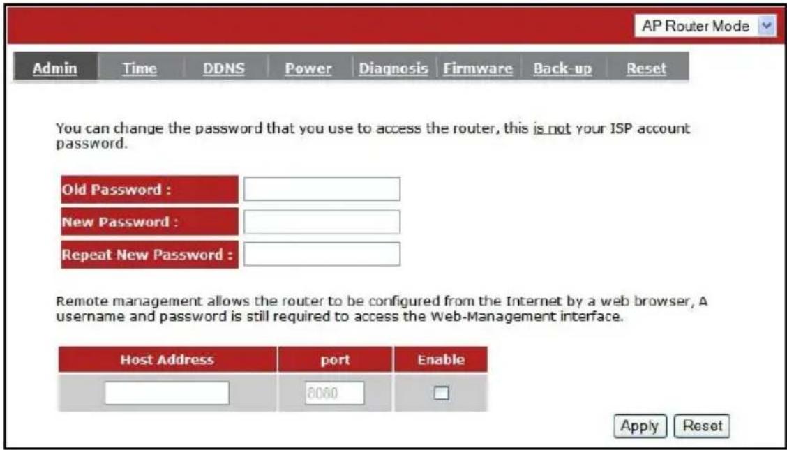
Old Password: Fill in the current password to allow changing to a new password.
New Password: Enter your new password and type it again in Repeat New Password for verification purposes
Remote management
Allows you to designate a host over the internet and the ability to configure the broadband router from a remote site. Enter the designated host IP Address in the Host IP Address field.
Host Address: This is the IP address of the host over in the Internet that will have management/configuration access to the Broadband router from a remote site. If the Host Address is left 0.0.0.0 this means anyone can access the router's web-based configuration from a remote location, provided they know the password.
Port: The port number of the remote management web interface.
Enabled: Check to enable the remote management function.
Click
Time Tab
The Time Zone allows your router to refer or base its time on the settings configured here, which will affect functions such as Log entries and Firewall settings.
Setting Up Time:
Synchronize with the NTP server

Time Zone: Select the time zone of the country you are currently located. The router will set its time based on your selection.
NTP Time Server: The router can be set up to use external NTP Time Server.
Daylight Savings: The router can also be set to automatically adjust to the Daylight Savings changes. If you wish to use this function, you must select the Daylight Savings Time period and put a checkmark on the Enable box to enable your daylight savings time configuration.
Click
Synchronize with your PC
You could synchronize the router's time with your computers time.
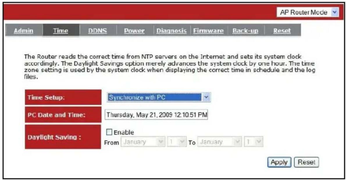
PC Date and Time: This field would display your computer's date and time.
Daylight Savings: The router can also take Daylight Savings into account. If you wish to use this function, you must select the Daylight Savings Time period and check/tick the enable box to enable your daylight saving configuration.
Click
DDNS Tab
DDNS allows you to map the static domain name to a dynamic IP address. You must register to a DDNS services and to get an account, password and your static domain name from the DDNS service providers. This router supports DynDNS, TZO and other common DDNS service providers.
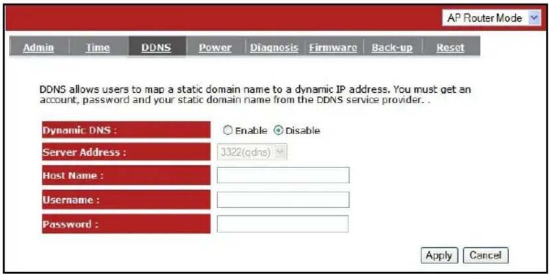
Enable/Disable DDNS: Enable or disable the DDNS function of this router
Server Address: Select a DDNS service provider
Host Name: Fill in your static domain name that uses DDNS.
Username: The account that your DDNS service provider assigned to you.
Password: The password you set for the DDNS service account above.
Click
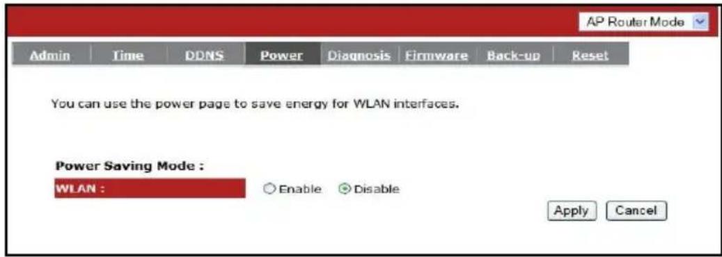
Power Tab
Saving power in WLAN mode can be enabled / disabled in this page.
Diagnosis Tab
In this page lets you run diagnosis to your network status.

Firmware Tab
This page allows you to upgrade the router's firmware. To upgrade the firmware of your Broadband router, you need to download the firmware file to your local hard disk, and enter that file name and path in the appropriate field on this page. You can also use the Browse button to find the firmware file in your PC.
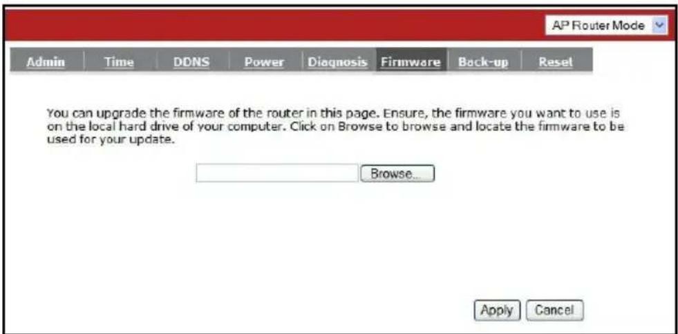
Once you've selected the new version of firmware file, click
Back-up Tab
This page allows you to save the current router configurations. When you save the configurations, you also can restore the saved configurations into the router through the Restore Settings. If extreme problems occur you can use the Restore to Factory Defaults to set all configurations to its original default settings. Warning: You will loose any saved data and settings when you set back to the manufacturer's default settings, but you can re-enter your previous settings manually.
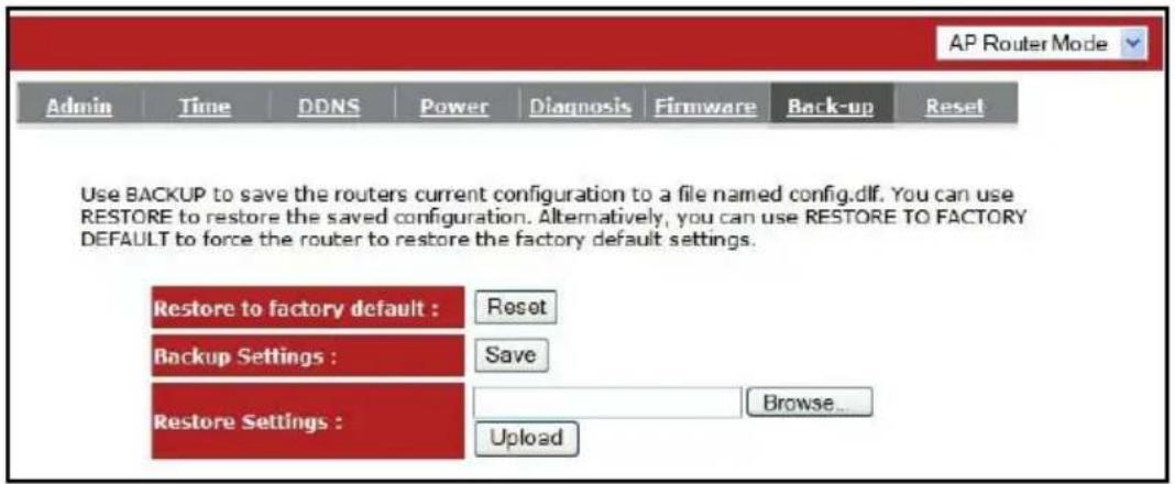
Backup Settings: This can save the current Broadband router configuration to a file named "config.bin" on your PC. You can also use the
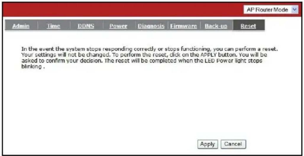
Reset Tab
You can reset the broadband router when system stops responding correctly or stop functions.
6. REPEATER MODE
Repeater mode has limited settings and features compared to the AP Mode. Choose "Repeater Mode" on the top right corner of the configuration page. The ENHWI-3GN3 will re-start and will lose connection to your computer.
Using the ENHWI-3GN3 as a wireless repeater requires good knowledge in computer either wired or wireless networking. You will need to have all the network data and information from the existing network, IP address being used and network design and architecture of the network you want to join in. If you don't have these data on hand at this time, stop and take all these information first, you will be asked to enter these data and other wireless information during the Repeater Mode setup. If after the successful repeater setup you see two SSID's with the same name as your existing wireless router, this means your existing wireless router and this ENHWI-3GN3 are within the same wireless range, therefore you don't need a wireless repeater.
Due to the ENHWI-3GN3 is now a repeater and not an Access Point anymore, its DHCP server will no longer functional. That means your computer will have no IP address to lease to, therefore your computer is IP Address free. To be able to connect back to the ENHWI-3GN3 repeater's setup interface, you have to manually assign a static IP address to your computer network interface card. Use IP Address range 192.168.0.2 to 192.168.0.254, then open your web browser and enter 192.168.0.1 (default). Once the Repeater Mode web interface screen is up, you may now start setting up the Repeater to join your existing wireless network.
You will see the configuration home page under "Repeater Mode". Notice the left pane with less selection than in AP Mode.
6.1 System
Status Tab
System status section allows you to monitor the current status of your router. It shows the Uptime, Hardware Information, Serial Number information, Firmware Version and other vital system information.

LAN Settings: This page displays the Broadband router LAN port's current LAN information.
WLAN Settings: You may need to scroll the screen down to see the WLAN settings.
Displays the wireless configuration details such as SSID, status (Connected / Disconnected), Security and Channel are shown.
LAN Tab:
The LAN Tabs shows LAN settings. LAN settings can be change as needed. If you are an entry level user, try opening a website from your computer. If you're successful and able to connect and browse the web site you opened without any problem, do not change any of the settings.
Click

IP address: This is the router's LAN IP address (Your LAN clients default gateway IP address). It can be changed based on your network architecture.
IP Subnet Mask: Specify a Subnet Mask IP address for your LAN segment.
802.1d Spanning Tree: This is disabled by default. If 802.1d Spanning Tree function is enabled, this router will use the spanning tree protocol to prevent network loops.
Event Log Tab
View operations log of the ENHWI-3GN3. This page shows the current system log of the ENHWI-3GN3 router. It displays any event occurred after system start up. Use the scroll bar to go down to the bottom of the page, the system log can be saved
![Repeater Mode Status LAN Log Monitor Language View the system operation information. day 1 00:01:24 [SYSTEM]: SCHEDULE, stop Power Save day 1 00:01:24 [SYSTEM]: SCHEDULE, Schedule Stopping day 1 00:01:22 [SYSTEM]: UPnP, start day 1 00:01:21 [SYSTEM]: WLAN[2.4G], Channel = 4 day 1 00:00:05 [SYSTEM]: WLAN, start LLTD day 1 00:00:05 [SYSTEM]: HTTP, start day 1 00:00:04 [SYSTEM]: NET, Firewall Disabled day 1 00:00:04 [SYSTEM]: NET, NAT Disabled day 1 00:00:04 [SYSTEM]: SCHEDULE, stop Power Save day 1 00:00:04 [SYSTEM]: NTP, start NTP Client Save Clear Refresh](/content/2026/05/1066818/images/1ee5b300c124d20d14315d26511ba86afb5d9128b03b1a1d5e6d6ddf1c98447a.jpg)
Monitor Tab
The Monitor Tab shows the bandwidth monitoring feature of each network interface of the ENHWI-3GN3 router, wireless or wired and of the network packet histogram for the network connection on WLAN. Auto refresh keeps information updated frequently.

bar
Bandwidth Monitor (WLAN) | Seconds | Rx (KBps) | Tx (KBps) | | :--- | :--- | :--- | | 0 | 9.2 | 0 | | 1 | 9.0 | 0 | | 2 | 8.8 | 0 | | 3 | 9.1 | 0 | | 4 | 8.5 | 0 | | 5 | 6.3 | 0 | | 6 | 9.0 | 0 | | 7 | 8.9 | 0 | | 8 | 9.0 | 0 | | 9 | 8.7 | 0 | | 10 | 6.3 | 0 | | 11 | 9.0 | 0 | | 12 | 8.9 | 0 | | 13 | 9.0 | 0 | | 14 | 8.7 | 0 | | 15 | 6.3 | 0 | | 16 | 9.0 | 0 | | 17 | 9.2 | 0 | | 18 | 8.7 | 0 | | 19 | 10.1 | 0 | | 20 | 11.5 | 0 | | 21 | 9.0 | 0 | | 22 | 9.0 | 0 | | 23 | 9.0 | 0 | | 24 | 9.0 | 0 | | 25 | 9.0 | 0 | | 26 | 9.0 | 0 | | 27 | 9.0 | 0 | | 28 | 9.0 | 0 | | 29 | 9.0 | 0 | | 30 | 12.5 | 0 | | 31 | 13.5 | 0 | | 32 | 14.5 | 0 | | 33 | 13.5 | 0 | | 34 | 12.5 | 0 | | 35 | 11.5 | 0 | | 36 | 12.5 | 0 | | 37 | 11.5 | 0 | | 38 | 12.5 | 0 | | 39 | 11.5 | 0 | | 40 | 12.5 | 0 | | 41 | 11.5 | 0 | | 42 | 12.5 | 0 | | 43 | 11.5 | 0 | | 44 | 12.5 | 0 | | 45 | 11.5 | 0 | | 46 | 12.5 | 0 | | 47 | 11.5 | 0 | | 48 | 12.5 | 0 | | 49 | 11.5 | 0 | | 50 | 9.0 | - | The chart displays the bandwidth values for Rx and Tx over time in a system interface, with Rx values ranging from -9.2 to +9.2 KBps and Tx values from -9.2 to +9.2 KBps, based on the status of the system interface.Language Tab
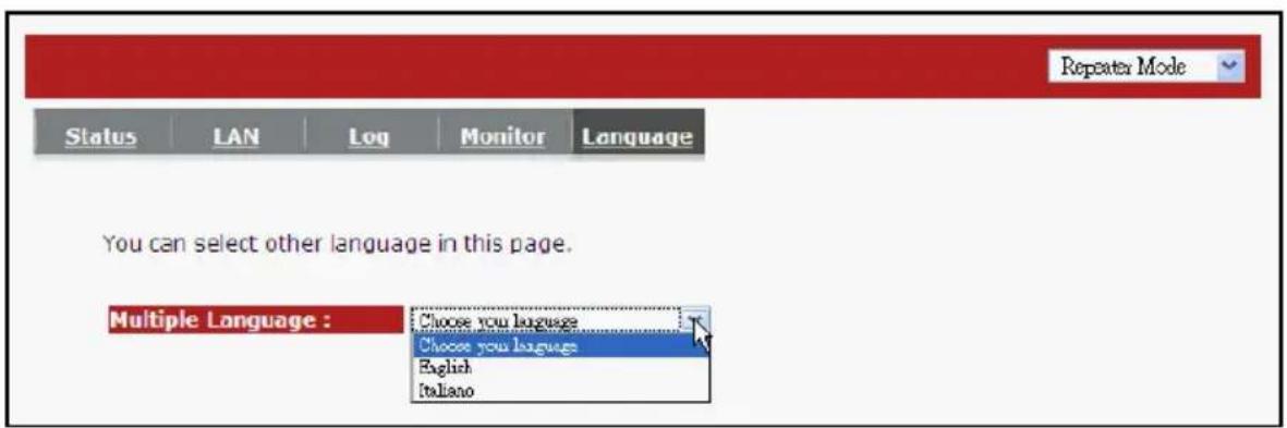
This Wireless Router supports multiple languages for user interface. Select your preferred language.
6.2 Wireless

Basic Tab
You can set the parameters used by the wireless stations to connect to this router. The parameter includes Mode, ESSID, Channel Number and Associated Client.
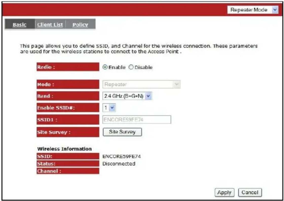
Radio: Enable or Disable Wireless function
Band: Allows you to set the frequency band of the router. Fix at 802.11b, 802.11g or 802.11n modes. You can also select B+G mode to allow 802.11b and 802.11g clients at the same time.
Enable ESSID: You can specify the maximum ESSID number. Maximum of 3.
ESSID1\~3: Allow you to specify up to 3 ESSID's of WLAN.
Site Survey: Click this button to scan the available wireless routers that can be set as this router's parent router. By doing so this ENHWI-3GN3 router will become a wireless extender / repeater of the selected parent router. Select one router from the list for that router to become this router's parent router.
Site Survey
| NO. | Select | Channel | SSID | BSSID | Encryption | Auth | Signal(%) | Mode |
| 1 | ○ | 1 | Encore | D0:02:6F:4F:5A:7F | TKIPAES | WPAPSKWPA2PSK | 5 | 11b/g |
| 2 | ○ | 1 | SENAOWL | D0:02:6F:53:0C:9B | WEP | AUTOWEP | 55 | 11b/g |
| 3 | ○ | 11 | SQA_ADSL | D0:0C:F6:47:C0:4C | TKIPAES | WPAPSKWPA2PSK | 100 | 11b/g/n |
| 4 | ○ | 3 | SNADSL | D0:02:6F:48:0D:8F | WEP | AUTOWEP | 20 | 11b/g |
| 5 | ○ | 4 | SQA7750B | D0:02:6F:5D:16:E8 | NONE | OPEN | 100 | 11b/g/n |
Client List Tab
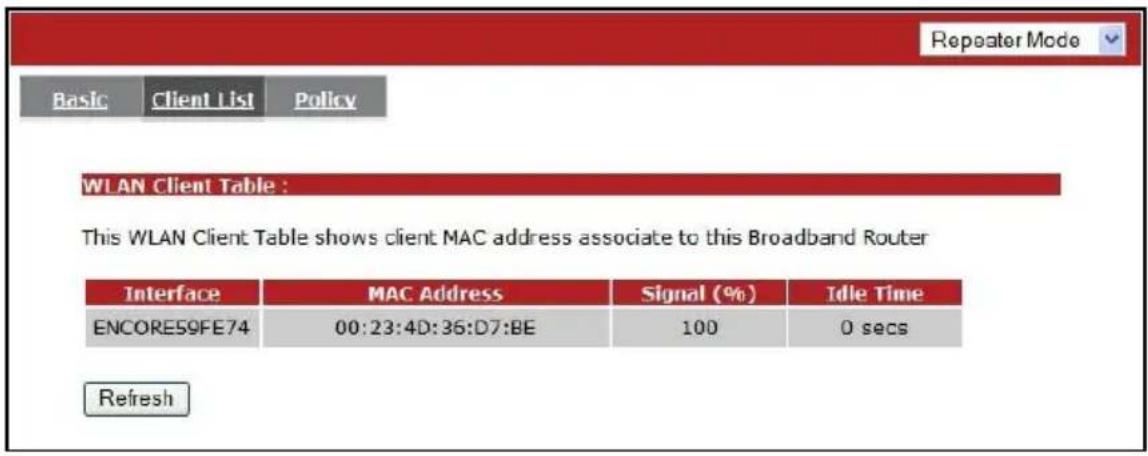
This WLAN Client Table shows the Wireless client associated to this Wireless Router.
Policy Tab
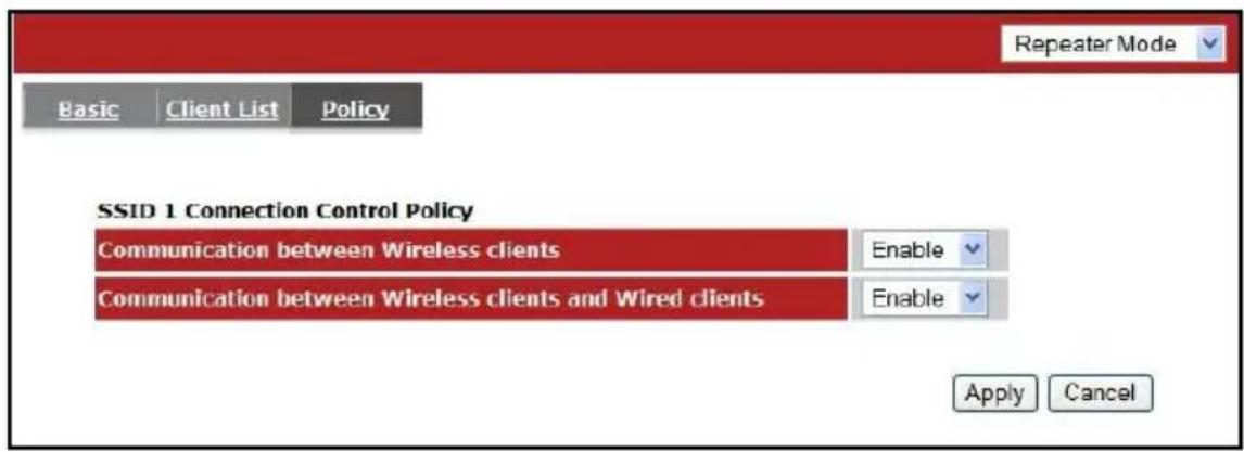
The Broadband router allows you to set up the Wireless Access Policy. If multiple SSID is created, this is the place to set the policy for each SSID.
Communication between Wireless clients:
This function is to allow other Wireless Client to communicate with another Wireless Client on the LAN connected on the same SSID.
Communication between Wireless clients and wired clients:
This function allows the Wireless Client to communicate with other Wireless Client in the LAN on specific SSID as well as the Wired Client connected to the switch portion of this router.
6.3 Tools
Admin Tab
You can change the password that is required to log into the broadband router's system web-based management. By default, the password is admin. Passwords can contain 0 to 12 alphanumeric characters, and are case sensitive.

Old Password: Fill-in the current password to be replaced. This is required to allow changing to a new password.
New Password: Enter your new password and again in Repeat New Password for verification purpose
Click
Time Tab
The Time Zone allows your router to use external source to time synchronizations. This affects other functions such as Event Log entries and Schedule settings that use time to do its tasks.
How to Set up Time:
Synchronize with the NTP server:

Time Zone: Select the time zone of the country you are located. The router will set its time based on your selection.
NTP Time Server: Enter the NTP Time Server address or URL here. This also accepts local the IP address if the NTP Time Server is on the same LAN.
Daylight Savings: The router can also setup to automatically adjust the Daylight Savings Time changes each time DST changes. To use this feature, click to put a checkmark on the Enable box then enter the dates the DST would starts and ends.
Click
Synchronize and use your computer's clock :
The ENHWI-3GN3 can be synchronized the time to your computer's time.

PC Date and Time: This field would display the user computers date and time.
Daylight Savings: The router can also setup to automatically adjust the Daylight Savings Time changes each time DST changes. To use this feature, click to put a checkmark on the Enable box then enter the dates the DST would starts and ends.
Click
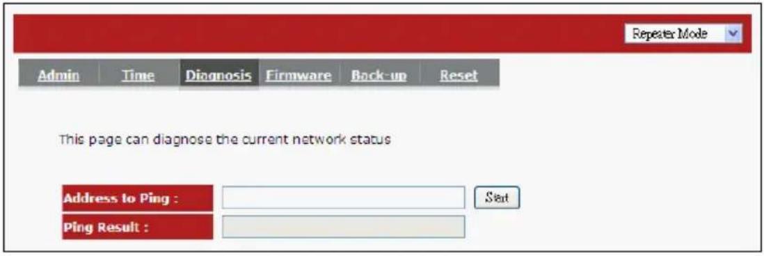
Diagnosis Tab
This page lets you diagnose the connection problem and the network status by executing the Ping function. The result tells you whether the connection is broken or successful.
Firmware
This page allows you to upgrade the router's firmware. To upgrade the firmware of your Broadband router, you need to download the firmware file to your local hard disk, and enter that file name and path in the appropriate field on this page. You can also use the Browse button to find the firmware file on your PC.

Once you've selected the new firmware file, click
Back-up Tab
The page allows you to save (Backup) the router's current configuration settings.
The saved backup can be restored again if needed by using the Restore Settings selection and browse the saved backup file to restore back to the expected settings. If restore is not an option the Restore to Factory Default may be the only way to recover the router from damage. Using Restore to Factory Default will reset all configurations and settings to its original factory default settings (e.g. when you first purchased the router).

Backup Settings: Use this function to save the router's current settings and configuration to a file named "config.bin" to your computer. You can also use the
Reset Tab
You can software reset the broadband router when system stops responding or stop working. This is different from the hardware reset that can reset the settings by physically pressing the button.

7. TECHNICAL SUPPORT
Please visit www.encore-usa.com for the latest product information and downloads.
International tech support hotlines are listed on the back cover.
APPENDIX A: FCC INTERFERENCE STATEMENT
Federal Communication Commission Interference Statement
This equipment has been tested and found to comply with the limits for a Class B digital device, pursuant to Part 15 of the FCC Rules. These limits are designed to provide reasonable protection against harmful interference in a residential installation. This equipment generates, uses and can radiate radio frequency energy and, if not installed and used in accordance with the instructions, may cause harmful interference to radio communications. However, there is no guarantee that interference will not occur in a particular installation. If this equipment does cause harmful interference to radio or television reception, which can be determined by turning the equipment off and on, the user is encouraged to try to correct the interference by one of the following measures:
● Reorient or relocate the receiving antenna.
- Increase the separation between the equipment and receiver.
- Connect the equipment into an outlet on a circuit different from that to which the receiver is connected.
- Consult the dealer or an experienced radio/TV technician for help.
This device complies with Part 15 of the FCC Rules. Operation is subject to the following two conditions: (1) This device may not cause harmful interference, and (2) this device must accept any interference received, including interference that may cause undesired operation.
FCC Caution: Any changes or modifications not expressly approved by the party responsible for compliance could void the user's authority to operate this equipment.
IMPORTANT NOTE:
FCC Radiation Exposure Statement:
This equipment complies with FCC radiation exposure limits set forth for an uncontrolled environment. This equipment should be installed and operated with minimum distance 20cm between the radiator & your body.
We declare that the product is limited in CH1\~CH11 by specified firmware controlled in the USA.
This transmitter must not be co-located or operating in conjunction with any other antenna or transmitter.
APPENDIX B: IC INTERFERENCE STATEMENT
Industry Canada statement:
This device complies with RSS-210 of the Industry Canada Rules. Operation is subject to the following two conditions:
(1) This device may not cause harmful interference, and (2) this device must accept any interference received, including interference that may cause undesired operation.
IMPORTANT NOTE:
Radiation Exposure Statement:
This equipment complies with IC radiation exposure limits set forth for an uncontrolled environment. This equipment should be installed and operated with minimum distance 20cm between the radiator & your body.
This device has been designed to operate with an antenna having a maximum gain of 2 dBi. Antenna having a higher gain is strictly prohibited per regulations of Industry Canada. The required antenna impedance is 50 ohms.

natural_image
Red and white abstract logo design with no text or symbols

natural_image
3D white figure holding a globe with continents, no text or symbols presentOur local tech support specialists are ready to help 24/7

LIVE SUPPORT
Argentina
Buenos Aires
+54 11-6632-2120
Córdoba
+54 35-1568-1873
soporte argentina@encore-usa.com
Brazil
suporte.brasil@encore-usa.com
Chile
+56 2-581-4903
soporte.chile@encore-usa.com
Colombia
+57 1-381-9274
soporte.colombia@encore-usa.com
México
+52 55-2789-5414
soporte.mexico@encore-usa.com
Perú
+51 1-708-5421
soporte.peru@encore-usa.com
USA
+1 626-608-3108
support@encore-usa.com
Spain
+34 912-919-405
Rest of Latin America
soporte.latinoamerica@encore-usa.com
* Local tech-support numbers are provided in selectively countries. Service may change without prior notice.
Please visit www.encore-usa.com for more details.

- TABLE OF CONTENTS
- INTRODUCTION ...... 2
- INSTALLATION .... 7
- SMART WIZARD.... 13
- HOW TO LOGIN TO THE WEB BASED USER INTERFACE ...... 26
- AP ROUTER MODE.... 28
- REPEATER MODE 81
- TECHNICAL SUPPORT....94
- APPENDIX A: FCC INTERFERENCE STATEMENT.... 94
- APPENDIX B: IC INTERFERENCE STATEMENT.... 94
- INTRODUCTION
- Summary
- Key Features
- Package Contents
- Product Layout
- Front Panel View
- INSTALLATION
- Network plus System Requirements
- Wall Mounting
- Best Location
- Setting Up LAN and 3G (WAN)
- LAN connection:
- 3G connection:
- ADSL or Cable Modem Broadband Connection:
- PC Network Adapter Setup
- Windows XP
- Powering Up The ENHWI-3GN3
- SMART WIZARD
- Before you start the ENHWI-3GN3 router's Smart Wizard, check for the followings:
- Step 1:
- Error Opening the page!
- Logging into the ENHWI-3GN3 router's User Interface for the first time:
- Note:
- Setting Up the Wireless LAN
- HOW TO LOGIN TO THE WEB BASED USER INTERFACE
- ENHWI-3GN3 web based user interface login procedure
- AP ROUTER MODE
- System
- Status Tab
- WAN Settings:
- LAN Settings:
- WLAN Settings:
- LAN Tab
- LAN IP
- DHCP Server
- DHCP Tab
- Schedule Tab
- Event Log Tab
- Monitor Tab
- Language Tab
- Wizard
- Internet
- Dynamic IP Tab
- Static IP Tab
- Point-to-Point Protocol over Ethernet (PPPoE) Tab
- Type:
- Point-to-Point Tunneling Protocol (PPTP) Tab
- 3G Tab
- Layer 2 Tunneling Protocol (L2TP) Tab
- WAN Interface Settings:
- L2TP Settings:
- Wireless Settings
- > Basic Tab
- WDS Mode
- MAC address 1\~4:
- Set Security:
- Advanced Tab
- Fragment Threshold:
- RTS Threshold:
- Beacon Interval:
- DTIM Period:
- Data Rate:
- N Data Rate:
- Channel Bandwidth:
- Preamble Type:
- CTS Protection:
- TX Power:
- Security Tab
- ESSID Selection:
- Broadcast ESSID:
- WMM:
- Encryption:
- Enable 802.1x Authentication
- WEP Encryption
- Authentication Type:
- Key Length:
- WPA Pre-Shared Key Encryption
- WPA-RADIUS Encryption
- MAC Address Filtering Table
- Adding an address into the list
- Remove an address from the list
- WPS Tab - Push Button Wireless Connection
- WPS: (Push Button Wireless Connection)
- WPS Current Status:
- Self Pin Code:
- SSID:
- Authentication Mode:
- Passphrase Key:
- Interface:
- WPS via Push Button:
- WPS via PIN:
- Client List Tab
- Policy Tab
- Firewall Settings
- Enable Tab
- Demilitarized Zone (DMZ) Tab
- ▶ Denial of Service (DoS) Tab
- MAC Filter Tab
- Add PC MAC Address
- Remove PC MAC Address
- IP Filter Tab
- Add PC IP Address
- Remove PC IP Address
- URL Filter Tab
- Add a URL Keyword
- Remove URL Keyword
- Advanced Settings
- Network Address Translation (NAT) Tab
- Port Mapping Tab
- Add Port Mapping
- Remove Port Mapping
- Port Forwarding Tab (Virtual Server)
- Add Port Forwarding
- Remove Port Forwarding
- Port Triggering Tab (Special Applications)
- Add Port Triggering
- Remove Port Triggering
- Application Layer Gateway (ALG) Tab
- UPNP Tab
- Quality of Service (QoS) Tab
- Priority Queue
- Bandwidth Allocation:
- Disable QoS
- Routing Tab
- Tools Settings
- Admin Tab
- Remote management
- Time Tab
- Setting Up Time:
- Synchronize with the NTP server
- Synchronize with your PC
- DDNS Tab
- Power Tab
- Diagnosis Tab
- Firmware Tab
- Back-up Tab
- Reset Tab
- REPEATER MODE
- System
- LAN Tab:
- Wireless
- Basic Tab
- Communication between Wireless clients:
- Communication between Wireless clients and wired clients:
- Tools
- How to Set up Time:
- Synchronize with the NTP server:
- Synchronize and use your computer's clock :
- Firmware
- TECHNICAL SUPPORT
- APPENDIX A: FCC INTERFERENCE STATEMENT
- Federal Communication Commission Interference Statement
- IMPORTANT NOTE:
- FCC Radiation Exposure Statement:
- APPENDIX B: IC INTERFERENCE STATEMENT
- Industry Canada statement:
- Radiation Exposure Statement:
- Our local tech support specialists are ready to help 24/7
- Argentina
- Brazil
- Chile
- Colombia
- México
- Perú
- USA
- Spain
- Rest of Latin America
Brand : ENCORE
Model : ENHWI-3GN3
Category : Router