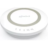
ESR1750 - Router ENGENIUS - Free user manual and instructions
Find the device manual for free ESR1750 ENGENIUS in PDF.


| Product Type | Wireless Router |
| Brand | EnGenius |
| Model | ESR1750 |
| Wireless Standards | IEEE 802.11a/b/g/n/ac |
| Frequency Band | Dual-band (2.4 GHz & 5 GHz) |
| Maximum Data Rate | 1750 Mbps (450 Mbps on 2.4 GHz + 1300 Mbps on 5 GHz) |
| Antennas | 6 x external detachable 5 dBi antennas |
| Ports | 4 x Gigabit LAN, 1 x Gigabit WAN, 1 x USB 2.0 |
| Power Supply | 12V DC, 2A |
| Dimensions (W x D x H) | 285 x 185 x 65 mm |
| Weight | Approximately 600 g |
| Security | WPA/WPA2, WEP, SPI Firewall, MAC Address Filtering |
| Management | Web-based interface, TR-069 |
| Maintenance | Keep firmware updated; clean with a dry, soft cloth; avoid moisture |
| Spare Parts | Power adapter, antennas, Ethernet cables |
| Repairability | Contact EnGenius support; not user-serviceable |
| General Information | Dual-band AC1750 router with gigabit ports and USB sharing |
Frequently Asked Questions - ESR1750 ENGENIUS
User questions about ESR1750 ENGENIUS
0 question about this device. Answer the ones you know or ask your own.
Ask a new question about this device
Download the instructions for your Router in PDF format for free! Find your manual ESR1750 - ENGENIUS and take your electronic device back in hand. On this page are published all the documents necessary for the use of your device. ESR1750 by ENGENIUS.
USER MANUAL ESR1750 ENGENIUS
with Gigabit Ports and USB
IMPORTANT
To install this router, please refer to the Quick Start Guide included in the product packaging.
To activate and use EnShare™ refer to the document "Using EnShare" also in the product packaging.
Table of Contents
Chapter 1 Product Overview....5
KeyFeatures....6
Technical Specifications / Software Features....8
Physical Interface....9
Chapter 2 Controlling the Router Through Its
Web Configuration Interface....10
Logging In....11
Viewing the Web Configuration Dash Board....12
Home Page....13
Web Menus Overview....14
Internet....15
Wireless 2.4 GHz....16
Wireless 5 GHz....17
Parental Controls....18
Guest Network....19
IPv6....20
Firewall....21
VPN....22
USB Port....23
Advanced....24
Tools....26
Chapter 3 Installation Setup Wizard....27
Internet Setup Wizard....28
Setting Up Your Internet Connection....29
Setting Your Wireless Security....30
Setting your Router's Administrator Password....31
Setting your Router's Time Zone....32
Status and Save Settings....34
Chapter 4 Basic Network Settings....35
Network Settings....36
Status....37
WAN Settings....38
LAN Settings....39
WLAN Settings....40
Guest Network....41
Configuring the LAN (Local Area Network)....42
DHCP Server....43
Configuring Dynamic Host Configuration Protocol....44
Enable Static DHCP IP....45
Current Static DHCP Table....46
Configuring Event Logging....47
Monitoring Bandwidth Usage....48
Configuring the System Language....49
Configuring IP Cameras....50
Configuring Internet Settings....51
Configuring Dynamic IP....52
DNS Servers....53
Configuring Static IP....54
Configuring PPPoE....55
Configuring PPTP....56
PPTP Settings....57
Configuring L2TP....58
L2TP Settings....59
Configuring DS-Lite....60
Wireless LAN Setup....61
Access Point Mode....62
Wireless Distribution System Mode....63
WDS Security Settings Screen....64
Chapter 5 Wireless Encryption....65
Wi-Fi Protect Access (WPA) Pre-Shared Key......66
Configuring Security....67
Encryption Type....68
WPA Radius....69
Wired Equivalent Privacy (WEP)....70
Configuring Filters....71
MAC Address Filtering Table....72
Configuring Wi-Fi Protected Setup....73
Configuring Client List....74
Chapter 6 Advanced Settings....75
Configuring Advanced Settings....76
Setting Up Parental Controls....78
Adding a Control Policy....79
Viewing Parental Policies....82
Guest Network....83
Configuring the DHCP Server Setting....84
Viewing the DHCP Client List on the Guest Network....85 IPv6....86
Viewing the IPv6 Connection Status....87
Configuring Static IPv6....88
Setting Autoconfiguration....89
Configuring PPPoE....90
Configuring 6to4....92
Viewing local Connections....93
Firewall Setup....94
Configuring Advanced Settings....95
Configuring Demilitarized Zone....97
Configuring Denial of Service....98
Virtual Private Network Setup....99
Configuring a VPN Tunnel Profile....100
General....101
SA (Security Association)....102
Network....103
Advanced....104
Configuring a User Setting....105
USB Port / Enshare....106
Viewing File Server....107
Viewing DLNA....108
Advanced Network Settings....109
Port Mapping Setup....110
Current Port Mapping Table....111
Port Forwarding Setup....112
Current Port Forwarding Table....113
Port Triggering Setup....114
Application Layer Getaway Setup....116
Universal Plug and Play Setup....117
Internet Group Multicast Protocol Setup....118
Quality of Service Setup....119
Priority Queue....120
Bandwidth Allocation....121
Routing Setup....122
Wake on LAN Setup....123
Tools Setup....124
System Time Setting....125
Synchronizing Time with a Computer....126
Dynamic Domain Name Service (DDNS) Setup....127
Diagnose That Client Devices Are Connected....128
Upgrading the Router's Firmware....129
Backing Up the Router's Settings....130
Rebooting the Router....131
Appendix....132
Wall Mounting the Router....133
FCC Interference Statement....134
Industry Canada Statement....135
Chapter 1
Product Overview

natural_image
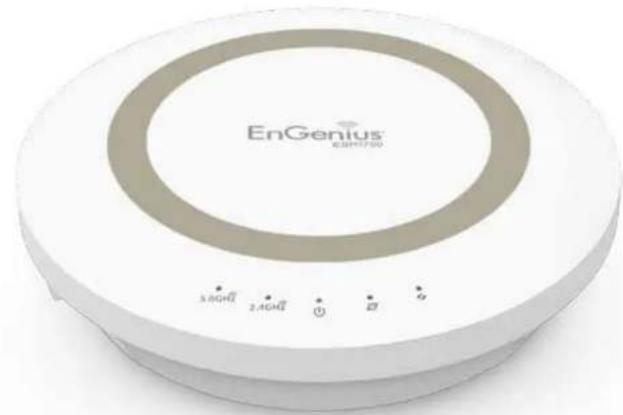
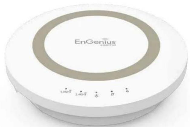
Exterior view of a circular electronic device labeled 'EnGenius' with control buttons at the bottom (no readable text beyond branding)Product Overview
Key Features
- Dual Band Wireless AC1750 Draft IEEE 802.11ac and IEEE 802.11 a/b/g/n
- Up to 450 Mbps in the 2.4 GHz frequency band and up to 1300 Mbps in 5 GHz
• Built-in 4-Port Gigabit Switch for optimal audio/visual streaming - USB Port to share and access media content in the home or when you're away from home with EnShare™
- Next Generation IPv6 Compliant
- Parental Controls
- Up to 8 Guest Access settings (4 per frequency band)
- Industry-standard Wireless Encryption and Security
• VPN Server Support Lite-Business Applications - Easy Setup Wizard
Robust and Reliable Wireless Performance
The ESR1750 is a Dual-Band Wireless AC1750 Router with a built-in 4-port Gigabit Ethernet switch. This cost effective router can connect to DSL or cable modems to provide high performance Internet access for desktop or laptop computers, tablets, smartphones and a wide variety of home entertainment devices, like HDTVs, set top boxes, Blu-ray players and game consoles.
The router's concurrent dual band design enables users to connect numerous wireless devices to it, giving them the

option to leverage Quantum Beam and the AC speed boost on the less congested 5 GHz frequency for bandwidth intensive applications like streaming HD video.
Maximum data rates are based on draft IEEE 802.11ac and IEEE 802.11 standards. Actual throughput and range may vary depending on many factors including environmental conditions, distance between devices, radio interference in the operating environment, and mix of devices in the network. EnGenius Technologies, Inc. EnShare™ supports both FAT32 and NTFS USB formats. Transfer speeds of data from your router-attached USB storage device to a remote/mobile device may vary based on Internet uplink and downlink speeds, bandwidth traffic at either send or receive locations, the data retrieval performance of the attached storage device or other factors. EnGenius does not guarantee compatibility with all USB drives. EnGenius does not warrant its products or EnShare from loss of data or loss of productivity time. Features and specifications subject to change without notice. Trademarks and registered trademarks are the property of their respective owners. For United States of America: Copyright ©2013 EnGenius Technologies, Inc. All rights reserved.
Product Overview
A Media Sharing Platform
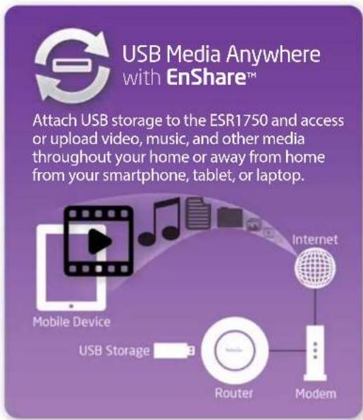
The ESR1750 is designed to access and share media for devices on the home network. In addition to connecting home entertainment components to any of its available Gigabit Ethernet ports, the ESR1750 also includes a USB port for attaching a USB storage device so wireless devices in the home or away from the home can access or upload media content wherever there is an available Internet connection through EnShare™ - Your Personal Cloud.
EnShare is available as an Internet portal for accessing stored media connected to the USB port of the router (See the Using EnShare document in the product packaging). EnShare will also be available as an app for Apple iOS devices (iPads, iPods and iPhones) and Android-based devices (smartphones, tablet PCs, Kindle and other mobile readers) soon. The apps will be available through Apple iTunes Store and Google Play respectively.
Industry-standard Wireless Security
The router supports a variety of security features and mechanisms including industry-standard WPA/WPA2 wireless encryption to prevent unauthorized access to your network. It also includes a built-in SPI (Stateful Packet Inspection) firewall to help prevent attacks from malicious software (malware) from the Internet. The router also supports IPv6.
More Guest Access Options
The ESR1750 also includes up to eight (8) separate and discrete Guest Access options allowing the router's administrator to assign different names (SSIDs-Service Set Identifiers) for each login to the home network so friends or visitors can access the user's Internet connection without accessing personal data stored on networked computers in the home.
Technical Specifications
Device Interface
Gigabit WAN Port
4 Gigabit LAN Ports
USB2.0 Port
Push Button for WPS
Reset Button
IEEE Standards
802.11ac (draft)
802.11a/b/g/n
Up to 450 Mbps wireless speed on 2.4 GHz frequency
band and 1300 Mbps on 5 GHz frequency band
802.3i/u/ab
LED Indicators
Power
WLAN (Wireless Connection)
Internet
Package Contents
ESR1750 Router
Power Adapter (12V 1.5 A)
Quick Start Guide
RJ45 Ethernet Cable
Power Specification
External Power Adapter
DC In, 12V 1.5A
Certifications
FCC/CE/IC
Physical/Environmental Conditions
Operating Temperature: 0°\~40° Celsius
Humidity: 90% or less (non-condensing)
Storage Temperature: -20°\~60° Celsius
Humidity: 95% or less (non-condensing)
Software Features
Frequency Bands
2.400\~2.484 GHz (11b/11g/11n)
5.18\~5.82 GHz (11a/11n)
Operating Mode
AP Router/WDS
Wireless Features
Auto Channel Selection
Output Power Control
WMM (Wireless Multimedia)
MSSID (Multiple SSID)
Security
WEP/WPA-PSK/WPA2-PSK
TKIP/AES
Hidden SSID
MAC Address Filtering
802.1X Authentication
DDoS
DHCP Server/Client
SPI (Stateful Packet Inspection)
NAT
Port Forwarding
DMZ
Port Mapping/Triggering
VPN Server (PPTP/L2TP)
VPN Client (PPTP/L2TP)
VPN Pass-through (PPTP/L2TP/IPSec)
Rule Based (IP Address Ranges, Port Block ICMP
VPN Tunnel (Maximum 5)
QoS
IP Filtering
Port Filtering
DDNS
IPv6 Pass-through
MAC Clone
Traffic Monitor
WAN Type: PPPoE/DHCP/Static IP
USB Features: SAMBA
Physical Interface
Dimensions and Weights
Weight: 0.5 lbs.
Diameter: 6.36"
Height: 1.64"

When considering the placement of the router
remember the following:
- It must be close to an electrical outlet.
- For optimal wireless connectivity, place the router near the center of the room if possible, at a high level

Other electronic devices and some architectural construction materials or impediments may interfere with the wireless signal(s) of the router and reduce its range or coverage. Try to minimize the number of walls or floors that the router's signal needs to penetrate to connect to other wireless devices.
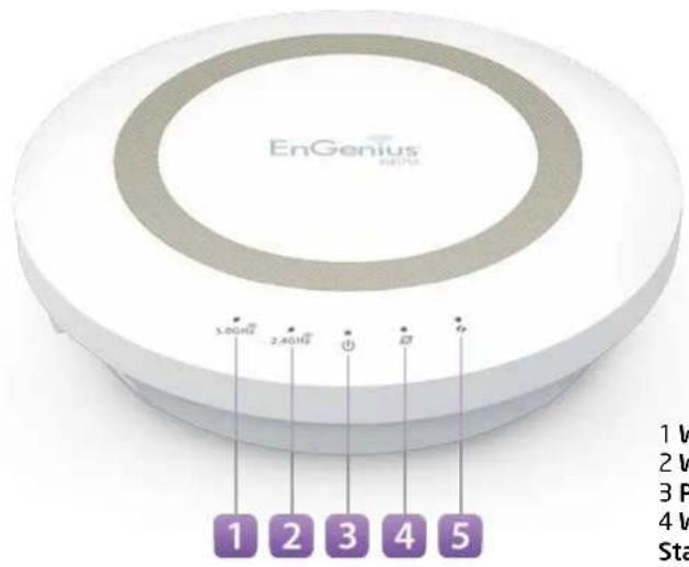
1 WLAN 5 GHz LED
2 WLAN 2.4 GHz LED
3 Power LED
4 WAN Port/(Internet)
Status LED
5 WPS (Wireless Protected
Setup) LED
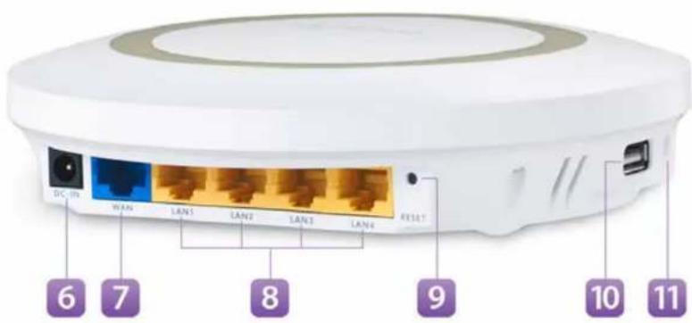
6 DC Power Jack – connects the ESR Series Router to its DC power adapter
7 WAN Port – connects the ESR Router to a cable or DSL modem to access the user's broadband (Internet) connection
8 LAN Ports (1 - 4) – for connecting home entertainment components, computers or other Ethernet-enabled devices using Ethernet cables
9 Reset Button – For resetting the router to its factory default settings by pressing button for more than 11 seconds or until the Power LED starts flashing.
10 USB Port for connecting a USB Storage Device
11 WPS Button – Wi-Fi Protected Setup button. To associate another WPS-enabled client device (computer, wireless media bridge, USB adapter, etc.) press the WPS button for 2 to 5 seconds on the router while also pressing the WPS button on the end device.
Chapter 2
Controlling the Router Through Its Web Configuration Interface
natural_image
Exterior view of a white EnGenius 3.8GHz radio receiver with control buttons (no text or symbols on body)Logging In
During the Quick Start Guide procedure, you should have successfully logged into the router's Web Configuration user interface (essentially the router's operating system that controls how it operates) and established some initial settings and controls for the router.
If you wish to change the router's settings (establish a new username and password for the person who manages and maintains the router, set Parental Controls, establish a Guest Access-SSID setting for visitors, or any number of other settings) you can log into the Web Configuration again through the web browser (Internet Explorer, Safari, Chrome, Firefox) on your computer or tablet device.
To do this, enter the router's default IP address of
192.168.0.1 into your browser's address window.
- At the login screen enter your username and a password
- Click Login to continue.

The default login settings are:
username: admin
password: admin
It's highly recommended that, if you haven't done so already, to change these default names, so your router and the devices connected to it on your home network are more secure.
Viewing the Web Configuration Dash Board
The Home Page screen of the Web Configuration interface, or dashboard, provides access to the router's settings and controls.

| Application Version | 0.0.4 |
| Hardware Version | 0.0.1 |
| Serial Number | 000000001 |
| MAC Address | 00:AA:BB:CC:DD:11 |
| Attain IP Protocol | Dynamic IP Address |
| IP Address | 192.168.1.22 |
| Subnet Mask | 255.255.255.0 |
| Default Gateway | 192.168.1 254 |
| IPv6 Connection Type | Link Local |
| IPv6 WAN Default Gateway | |
| LAN IPv6 Link-Local Address | FE80::2AA:BBFF:FECC:DD10 |
| DHCP-PD Wireless 2.4GHz : | Disabled |
| SSID_1 Security Type Wireless 5GHz : | EnGeniusCCDD10 WPA Pre-Shared key |
| SSID_1 Security Type | EnGeniusCCDD11 WPA Pre-Shared key |
Home Page
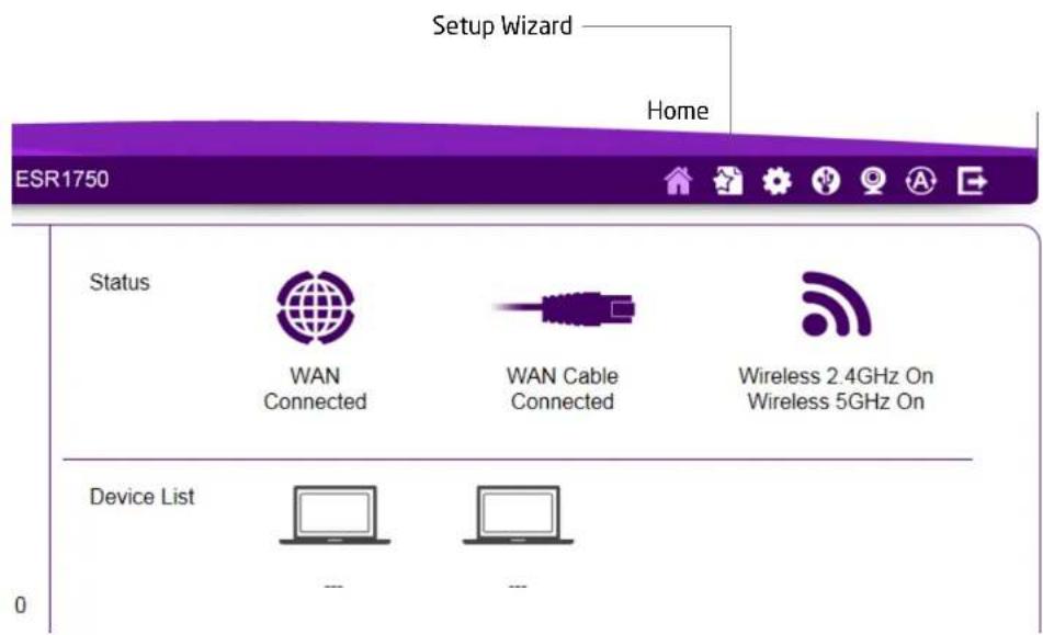
The Home Page displays the areas within the Web Configuration to which you can navigate: Setup Wizard, Network Settings, USB Storage Sharing, IP Cam Viewer, Language, and Logout
Home
The Home link takes you back to the dashboard screen no matter where you are in the Web Configuration interface.
Setup Wizard
The Setup Wizard link starts the wizard that automatically configures the router.
Network Settings
The Network Settings link displays the menus to manually configure the router.
USB Storage Sharing
The USB Storage Sharing link displays the menus to access shared storage devices connected to the router.
IP Cam Viewer
The IP Cam Viewer link displays the menus to view an IP camera connected to the network.
Language
The Language link displays the menu to set the OSD language.
Logout
The Logout link closes the router's Web Configuration interface from any screen.
Web Menus Overview
System
View and edit settings that affect system functionality.
Operation Mode
Configure the device to be a router or WDS access point.
Status
Displays the summary of the current system status.
Schedule
Schedule services to start and stop at specific times or intervals.
Event Log
View recorded system operations and network activity events.
Monitor
View the current network traffic bandwidth usage.
Language
Configure the application menu and GUI language.
IP Camera
View the IP cameras connected to the ESR Series Router.
| System | |
| Status | |
| LAN | |
| DHCP | |
| Log | |
| Monitor | |
| Language | |
| IP Camera | |
| Internet | |
| Wireless | |
| Parental Control | |
| Guest Network | |
| IPv6 | |
| Firewall | |
| VPN | |
| USB Port | |
Internet
View and edit settings that affect network connectivity.
Status
Displays a summary of the Internet status and type of connection.
Dynamic IP
Setup a dynamic IP connection to an ISP (Internet Service Provider).
Static IP
Setup a static IP connection to an ISP.
PPPoE
Setup a PPPoE connection to an ISP.
PPTP
Setup a PPTP connection to an ISP.
L2TP
Setup an L2TP connection to an ISP.
| System | |
| Internet | |
| Status | |
| Dynamic IP | |
| Static IP | |
| PPPoE | |
| PPTP | |
| L2TP | |
| DS-Lite | |
| Wireless 2.4GHz | |
| Wireless 5GHz | |
| Parental Control | |
| Guest Network | |
| IPv6 | |
| Firewall | |
Wireless 2.4 GHz
View and edit settings for 2.4 GHz wireless network connectivity.
Status
View the current wireless connection status and related information.
Basic
Configure the minimum settings required to setup a wireless network connection.
Advanced
Configure the advanced network settings.
Security
Configure the wireless network security settings.
Filter
Establish a list of client devices (computer, tablets, smartphones, printers, etc.) based on their MAC (Media Access Control) numbers that are allowed to wirelessly connect to the 2.4 GHz network.
WPS
Automates the connection between a wireless device and your encrypted router using an 8-digit PIN.
Client List
View the 2.4 GHz wireless devices currently connected to the network.
| System | |
| Internet | |
| Wireless 2.4GHz | |
| Basic | |
| Advanced | |
| Security | |
| Filter | |
| WPS | |
| Client List | |
| Wireless 5GHz | |
| Parental Control | |
| Guest Network | |
| IPv6 | |
| Firewall | |
| VPN | |
| USB Port | |
| Advanced | |
| Tools |
Wireless 5 GHz
View and edit settings for 5 GHz wireless network connectivity.
Status
View the current wireless connection status and related information.
Basic
Configure the minimum settings required to setup a wireless network connection.
Advanced
Configure the advanced network settings.
Security
Configure the wireless network security settings.
Filter
Establish a list of client devices (computer, tablets, smartphones, printers, etc.) based on their MAC (Media Access Control) numbers that are allowed to wirelessly connect to the 5 GHz network.
WPS
Automates the connection between a wireless device and your encrypted router using an 8-digit PIN.
Client List
View the 5 GHz wireless devices currently connected to the network.
| System |
| Internet |
| Wireless 2.4GHz |
| Wireless 5GHz |
| Basic |
| Advanced |
| Security |
| Filter |
| WPS |
| Client List |
| Parental Control |
| Guest Network |
| IPv6 |
| Firewall |
| VPN |
| USB Port |
| Advanced |
| Tools |
Parental Controls
View and edit settings for parental controls.
Wizard
Enable or disable the Parental Controls function. The menu also provides information for configuring parental control policies.
Web Monitor
The menu provides a log of the events for defined parental control policies.
| System | |
| Internet | |
| Wireless 2.4GHz | |
| Wireless 5GHz | |
| Parental Control | |
| Wizard | |
| Web Monitor | |
| Guest Network | |
| IPv6 | |
| Firewall | |
| VPN | |
| USB Port | |
| Advanced | |
| Tools |
Guest Network
View and edit settings for a guest network.
Selection
Enable or disable the Guest Network function.
DHCP Server Setting
Configure the Guest Network DHCP server settings.
DHCP Client List
Configure the Guest Network client list.
| System | |
| Internet | |
| Wireless 2.4GHz | |
| Wireless 5GHz | |
| Parental Control | |
| Guest Network | |
| Selection | |
| DHCP Server Setting | |
| DHCP Client List | |
| IPv6 | |
| Firewall | |
| VPN | |
| USB Port | |
| Advanced | |
| Tools |
IPv6
View and edit settings for the IPv6 protocol.
Basic
Allows you to enable or disable the IPv6 and IPv6 Pass-through functions.
Status
Shows IPv6 LAN connection details.
Static IPv6
Configure the IPv6 protocol.
Auto Configuration
Configure the IPv6 by obtaining the information through the ISP provider.
PPPoE
Configure the PPPoE network protocol, obtain information from your ISP (Internet Service Provider).
6to4
Allows IPv6 packets to be transmitted over an IPv4 network.
Link Local
Configure the IPv6 link local address.
| System |
| Internet |
| Wireless 2.4GHz |
| Wireless 5GHz |
| Parental Control |
| Guest Network |
| IPv6 |
| Basic |
| Status |
| Static IPv6 |
| Auto Configuration |
| PPPoE |
| 6to4 |
| Link Local |
| Firewall |
| VPN |
| USB Port |
| Advanced |
| Tools |
Firewall
View and edit settings for the network firewall.
Basic
Enable or disable the network firewall.
Advanced
Configure virtual private network (VPN) packets.
DMZ
Redirect packets from the WAN port IP address to a particular IP address on the LAN.
DoS
Enable or disable blocking of DoS (Denial of Service) attacks.
ACL
Configure access control lists.
| System |
| Internet |
| Wireless 2.4GHz |
| Wireless 5GHz |
| Parental Control |
| Guest Network |
| IPv6 |
| Firewall |
| Basic |
| Advanced |
| DMZ |
| DoS |
| ACL |
| VPN |
| USB Port |
| Advanced |
| Tools |
VPN
View and edit settings for VPN tunnelling.
Status
View the status of current VPN tunnels.
Profile Setting
Manually configure VPN tunnels.
User Setting
Configure users, user ID and password combinations, and assign access to specific VPN tunnels.
Wizard
Automatically configure VPN tunnels with guidance from the software.
| System | |
| Internet | |
| Wireless 2.4GHz | |
| Wireless 5GHz | |
| Parental Control | |
| Guest Network | |
| IPv6 | |
| Firewall | |
| VPN | |
| Status | |
| Profile Setting | |
| User Setting | |
| Wizard | |
| USB Port | |
| Advanced | |
| Tools | |
USB Port
For viewing and editing settings for storage sharing.
EnShare™
Enables or disables the EnShare remote access function.
File Sharing
Enables or disables the Samba sharing function.
File Server
Enables and configures the File Server function.
DLNA
Enables the discovery of DLNA devices (some HDTVs, game consoles, some set top boxes/media players, Blu-ray players, some smartphones, and network attached storage) on the home network.
| System | |
| Internet | |
| Wireless 2.4GHz | |
| Wireless 5GHz | |
| Parental Control | |
| Guest Network | |
| IPv6 | |
| Firewall | |
| VPN | |
| USB Port | |
| EnShare | |
| File Sharing | |
| File Server | |
| DLNA | |
| Advanced | |
| Tools |
Advanced
View and configure advanced system and network settings.
NAT
Enable or disable Network Address Translation (NAT).
Port Mapping
Re-direct a range of service port numbers to a specified LAN IP address.
Port Forwarding
Configure server applications to send and receive data from specific ports on the network.
Port Triggering
Configure applications that require multiple connections and different inbound and outbound connections.
ALG
Configure the application layer gateway (ALG).
UPnP
Enable or disable Universal Plug and Play (UPnP) functionality.
IGMP
Enable or disable the Internet Group Multicast Protocol (IGMP).
QoS
Configures the network quality of service (QoS) setting by prioritizing the uplink and downlink bandwidth.
Routing
Configure static routing.
WOL (Wake On LAN)
Configure Wake on LAN to turn on a computer over the network.
Tools
For viewing and configuring the router's operating system and network tools settings.
Admin
For setting the administrator's password used to log into the router.
Time
For configuring the system time on the router.
DDNS
Maps a static domain name to a dynamic IP address.
Diagnosis
To perform a Ping test to verify whether a specific device is connected to the LAN.
Firmware
For updating the router's firmware.
Backup
For loading or saving the configuration settings to or from a backup file or to restore the router to its factory default settings.
Reset
Reboots the router.
| System | |
| Internet | |
| Wireless 2.4GHz | |
| Wireless 5GHz | |
| Parental Control | |
| Guest Network | |
| IPv6 | |
| Firewall | |
| VPN | |
| USB Port | |
| Advanced | |
| Tools | |
| Admin | |
| Time | |
| DDNS | |
| Diagnosis | |
| Firmware | |
| Back-up | |
| Reset |
Chapter 3
Installation Setup Wizard
natural_image
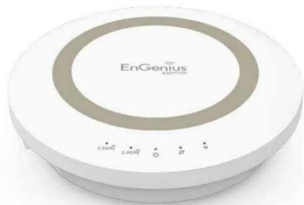
Exterior view of a circular electronic device labeled 'EnGenius' with control buttons (no readable text beyond branding)Internet Setup Wizard
Use the Wizard to detect and set up the type of Internet connection you need, to set up a secure wireless connection, to create an administrator password to secure the device, or set the router's date and time properties.
To use the Internet Setup Wizard, follow these steps:
- Click the Wizard button to show the Wizard start screen.
- Click Next to continue with the setup procedure.

Setting Up Your Internet Connection
- Decide how to set up the Internet connection.

Note: It is recommended to let the device setup the Internet connection automatically.
- Select Auto Detect to let the Wizard set up the Internet connection.
-
Select Manual Setup to set the properties yourself.
-
Click Next to continue or Prev to return to the previous screen.

If you selected Manual Setup, follow these steps:
- Select the Internet connection type and enter the connection properties.

Note: The connection types available are static IP, PPPoE, Dynamic IP, PPTP, and L2TP.
- Click Next to continue, Prev to return to the previous screen, or Cancel to stop the procedure.

Setting Your Wireless Security
Setting wireless encryption for 2.4 GHz and 5 GHz networks.
To encrypt the wireless signals for either or both of the frequency bands in the ESR1750 router, follow these steps:
- Enter the router name in the wireless Name (SSID) text field.
- Select the security level from the Encryption dropdown list.

Important: To ensure the network is secure, it is recommended to select High for an encryption level.
- Enter a password in the Encryption Key text field.
- Repeat steps 1 through 3 to encrypt the 5 GHz band
- Click Next to continue, Prev to return to the previous screen, or Cancel to stop the procedure.

Setting Your Router's Administrator Password
Set up a password to log into the ESR Series Router.
- Enter a password in the New Password text field.
- Enter the same password in the Repeat New Password text field.
- Click Prev to return to the previous screen, Skip to skip this procedure, Next to continue, or Cancel to stop the procedure.
Step 3. Setup your Device Password
Create a password to login and access your router
Note: This is not the password provided by Internet Service Provider (ISP).
New Password
Repeat New Password

Setting Your Router's Time Zone
Setup date and time synchronization on the ESR Series Router with a computer or an Network Time Protocol (NTP) server.
To synchronize date and time settings with a computer, follow these steps:
- Select Synchronize with PC (computer) from the Time Setup dropdown list. The date and time values are shown in the PC Date and Time text field.
- Click Prev to return to the previous screen, Apply to save the settings, or Cancel to stop the procedure.
To synchronize the date and time settings with an NTP server, follow these steps:
- Select Synchronize with NTP Server from the Time Setup dropdown list.
- Select a time zone value from the Time Zone dropdown list.
- Enter an IP address or domain name of an NTP server in the NTP Server text field.

- Click the Enable Daylight Savings check box to enable or disable daylight savings time.
-
Select the date and time values when daylights savings time starts in the Start Time dropdown lists.
-
Select the date and time values when daylights savings time ends in the End Time dropdown lists.
Step 4. Setup your Device Time Zone
Set up time zone for your router to synchronize with Network Time Protocol(NTP) Server or with PC.
Click Apply to complete the settings
Time Setup
Synchronize with PC
PC Date and Time
Monday, June 17, 2013 3:59:33 PM
Prev
Apply
Cancel
- Click Prev to return to the previous screen, Apply to save the settings, or Cancel to stop the procedure.
Status and Save Settings
This screen lets you review, change and save your Internet connection, save wireless security settings or setup up a user-specified name for the default EnGenius DDNS service.
To review or modify the device settings, follow these steps:
- Review the settings shown on the screen for the Internet connection, 2.4 GHz and 5 GHz networks, and the router administrator login.
- You can change settings to the Internet connection and wireless network settings by clicking the Setup button.
You may wish to use a different name that's easier to remember for the default EnGenius DDNS service used for the EnShare™ feature. To specify your own DDNS name, follow these steps:
-
The Enable option should be selected by default.
a. Enter the name in the Domain Name text field.
b. Select a time interval to refresh the DNS records from the Refresh dropdown list.
c. Click Apply to save the DDNS name you have entered. -
Click Save to exit the Web Configuration interface. The router will reboot (restart) to apply all the settings you've specified. Devices connected to the router will temporarily lose their Internet connection. The reboot may take several seconds before the router and your Internet connection are once again available.


WARNING! Selecting Disable in the DDNS Settings/Status field will disconnect the router's connection to the default EnGenius DDNS server and as a result will disable the EnShare feature which lets you access media from a USB storage device connected to your ESR pod router when you're away from your home.
Chapter 4
Basic Network Settings
natural_image
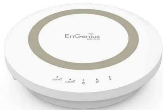
Exterior view of a circular electronic device labeled 'EnGenius' with control buttons at the bottom (no readable text beyond branding)Network Settings
Viewing System Status
To see a more detailed view of the router's status than the information displayed on the Home page of the Web Configuration interface, from the Home Page click on Network Settings button in the upper navigation bar.

EnGenius®
ESR1750
EnGenius Wireless Router ESR1750


| System Status LAN DHCP Log Monitor Language IP Camera Internet Wireless 2.4GHz Wireless 5GHz Parental Control Guest Network IPv6 Firewall VPN USB Port | System Model ESR1750 Mode AP Router Uptime 9 min 39 sec Current Date/Time 2013/06/17 18:14:01 Hardware Version 1.0.0 Serial Number 134211653 Application Version 1.0.0 WAN Settings Attain IP Protocol Static IP IP Address 67.130.140.145 Subnet Mask 255.255.255.0 Default Gateway 67.130.140.100 MAC Address 00:02.6F:FD:8A:BB Primary DNS 4.2.2.2 | TIPS Status page shows the summary of current system status including System (hardware/ software version, date/ time), Internet connection (WAN Settings), Wired (LAN Settings) and Wireless Network (WLAN) Information. |
Status
To view the Status settings, click System then click Status.
On the Status page, you can view a summary of the current router system status including the router's (hardware/software version, date/time), wired network (LAN) and wireless network (WLAN) information.
Model
The model name of the ESR Series Router.
Mode
The operating mode of the ESR Series Router.
Uptime
The amount of time the ESR Series Router has been connected for the current session.
Current Date/Time
The current system date and time.
Hardware Version
The hardware version number of the router.
Serial Number
The serial number of the router (required for customer service or support).
Application Version
The version of the router's firmware.

Note: To update the router's firmware, visit www.engeniustech.com and go to the product page for your router, then select the Downloads tab at the bottom of the web page to see if a newer version of the firmware is available.
WAN Settings
Attain IP Protocol
Displays the IP protocol in use for the router. It can be a dynamic or static IP address.
IP Address
The router's IP address as designated by an ISP (Internet Service Provider).
Subnet Mask
The router's WAN subnet mask as designated by an ISP provider.
Default Gateway
The router's gateway address as designated by an ISP provider.
MAC Address
The router's WAN MAC (Media Address Control) address. The router's MAC address is located on the label on the bottom panel of the router and is unique for each router.
Primary DNS
The primary DNS of an ISP provider.
Secondary DNS
The secondary DNS of an ISP provider.
| WAN Settings | |
| Attain IP Protocol | Dynamic IP Address |
| IP Address | 192.168.1.76 |
| Subnet Mask | 255.255.255.0 |
| Default Gateway | 192.168.1.254 |
| MAC Address | 00:02:6F:FD:8B:D1 |
| Primary DNS | 192.168.1.254 |
| Secondary DNS | --- |
LAN Settings
IP Address
The router's local IP address. The default LAN IP address is
http://192.168.0.1
To access the Web Configuration interface for the router, type this address into the address (URL) field of your web browser. This can only be done in the same physical location where the router resides (your home network).
Subnet Mask
The router's local Subnet Mask.
DHCP Server
The DHCP setting status (Default: Enabled). The DHCP (Dynamic Host Control Protocol) is a software mechanism in your router that assigns IP addresses to wired and wireless devices on your network, for example, a computer, printer, tablet or HDTV on your network may be assigned an IP address of http://192.168.0.104. Note how the address is essentially an extension or addition of your router's IP address.
MAC Address
The router's unique MAC address.
LAN Settings
| IP Address | 192.168.0.1 |
| Subnet Mask | 255.255.255.0 |
| DHCP Server | Enabled |
| MAC Address | 00:02:6F:FD:8C:6A |
WLAN Settings
Channel
The communications channel used by all stations, or computing devices, on the network.
ESSID
The ID value of a set of one or more interconnected basic service sets (BSSs).
Security
The security setting status (Default: Disabled).
BSSID
The unique ID of the BSS using the above channel value on this router. The ID is the MAC address of the BSSs access point.
Associated Clients
The number of clients associated (actively linked to the router via a wireless or wired/Ethernet connection) with this SSID.
| WLAN Settings | |
| Wireless 2.4GHz Setting | |
| Channel | 11 |
| SSID_1 | |
| ESSID | esr1200 |
| Security | WPA2 Pre-Shared key |
| BSSID | 00:02:6F:FD:8C:6A |
| Associated Clients | 1 |
| Wireless 5GHz Setting | |
| Channel | 44 |
| SSID_1 | |
| ESSID | EnGeniusFD8C6B |
| Security | WPA2 Pre-Shared key |
| BSSID | 00:02:6F:FD:8C:6B |
| Associated Clients | 0 |
Guest Network
Guest Network
The guest network status. (Default: Disabled)
IP Address
The Guest Network's LAN IP address.
Subnet Mask
The Guest Network's local subnet mask.
DHCP Server
The Guest Network DHCP setting status (Default: Enabled).
Guest Network Interface
The SSID (Service Set Identifier) of the Guest Network.
| Guest Network | Enabled |
| IP Address | 192.168.169.1 |
| Subnet Mask | 255.255.255.0 |
| DHCP Server | Enabled |
| Guest Network Interface | SSID_2 |
Configuring the LAN (Local Area Network)
The settings on this page allow you to configure the wired network settings. Devices connected to the router's Ethernet ports comprise its LAN. The router's IP is defined in the IP Address field. The default setting of the DHCP server is set to Enabled so that networked clients (computers, home entertainment components, printers, etc.) will automatically be assigned IP addresses by the router.
More advanced users may wish to configure the DNS server settings to meet their specific requirements. Changing the settings in this section are not necessary for most situations.
To view the LAN settings, click System, then click LAN.

Note: Keep the router's default values if you are uncertain of the settings values.
LAN IP
IP Address
IP Subnet Mask
802.1d Spanning Tree
DHCP Server
DHCP Server
Lease Time
Start IP
End IP
Domain Name
192.168.1.53
255.255.255.0
Disabled
Disabled
One Day
1921681100
192 168 1 200
ESR600
Apply
Cancel
LAN IP
IP Address
For configuring the router's LAN IP address.
IP Subnet Mask
For configuring the router's LAN Subnet Mask
802.1d Spanning Tree
Spanning Tree is disabled by default. When enabled, Spanning Tree prevents network loops (transmissions won't pass the same node twice or several times to reach the destination).
Note:
The default device IP address is 192.168.0.1.
DHCP Server
The DHCP server assigns IP addresses to the devices on the LAN.
DHCP Server
Enable or disable the DHCP server (Default: Enabled).
Lease Time
Configure the amount of time each allocated IP address can be used by a client.
Start IP
The first IP address in the range of addresses assigned by the router.
End IP
The last IP address in the range of addresses assigned by the router.
Domain Name
The domain name of the router.
LAN IP
IP Address
IP Subnet Mask
802.1d Spanning Tree
DHCP Server
DHCP Server
Lease Time
Start IP
End IP
Domain Name
192.168.1.53
255.255.255.0
Disabled
Disabled
One Day
1921681100
192 168.1 200
ESF600
Apply Cancel
Configuring Dynamic Host Configuration Protocol
This window allows you to view and configure Dynamic Host Configuration Protocol (DHCP) addresses.

WARNING! Do not modify the settings in this section without a thorough understanding of the parameters.
To view the DHCP settings, click System then click DHCP.
DHCP Client Table
Displays the connected DHCP clients whose IP addresses are assigned by the DHCP server of the router.
IP Address
Displays the IP address of the static DHCP client device in the table.
MAC Address
Displays the MAC address of the static DHCP client device in the table.
Expiration Time
The date and time when the current DHCP address is no longer valid.
Click Refresh to update the table.
| Current Static DHCP Table | |||
| No. | IP Address | MAC Address | Select |
| 1 | 192.168.0.99 | 00:02:6F:FD:8D:C5 | |
Enable Static DHCP IP
There are reasons why you may want to enable a static IP address on a client device on your ESR router's network.
On occasion, if there are power outages or if you've reconfigured the settings on your ESR router and reboot (restart) it to apply the new settings, the previous IP address that the router's DHCP server assigned to one or more devices on the network may have changed. Some client devices on your network may also have web configuration interfaces (set top boxes, Network Attached Storage, etc.) that are accessible from the router's assigned IP address from its DHCP server, so the client device can be managed. Thus if the client device's IP address changes from time to time, it may be difficult linking to it unless you find its new address through the ESR router's DHCP Client Table.
If you wish to avoid this, then the Enable Static DHCP IP option allows you set a static (essentially a permanent) address for given client devices on your network.
To do so, select the Enable Static DHCP IP option.
IP Address
Enter the IP address of the device to add as a static DHCP client.

MAC Address
Enter the MAC address of the device to add as a static DHCP client.
Click Add to add the device to the static DHCP client table or Reset to return the table to its previous state.
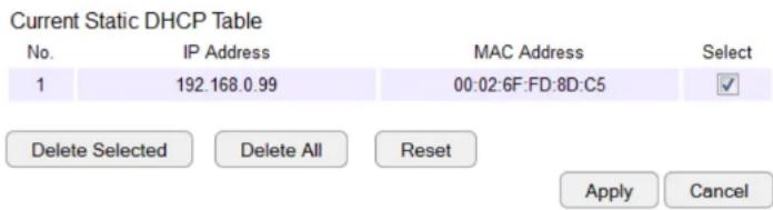
Current Static DHCP Table
Allows you to view the active static DHCP IP addresses that have been manually assigned to client devices with their corresponding MAC addresses.
No. (Number)
Displays the ID of the static DHCP client device in the table.
IP Address
Displays the IP address of the static DHCP client device in the table.
MAC Address
Displays the MAC address of the static DHCP client device in the table.
Select
Click to select static DHCP client devices to be deleted.
Click Delete Selected to remove a selected address. Click Delete All to remove all addresses from the table. Click Reset to return the table to its previous state. Click Apply to save the settings or Cancel to discard changes.
Configuring Event Logging
The logging service records and displays important system information and activity on the network. The events are stored in a memory buffer with older data overwritten by newer when the buffer is full.
To view the Log settings, click System then click Log.
Log Message List
Select Enable Logging to Syslog Server
Click Save to start logging information to the system.
Log Message window
Shows the current system operations and network activity. Click Save to save the message list to a text file, Clear to discard message from the memory buffer, or Refresh to clear previous messages and write new messages to the memory buffer. Click Apply to save changes.
SysLog Settings
Enable Logging To Syslog Server :

![day 0 10:59:05 [SYSTEM]: NET, start Firewall day 0 10:59:05 [SYSTEM]: NET, start NAT day 0 10:59:05 [SYSTEM]: NET, stop Firewall day 0 10:59:05 [SYSTEM]: NET, stop NAT day 0 10:59:04 [SYSTEM]: DHCP, start DHCP Server day 0 10:59:03 [SYSTEM]: DHCP, DHCP Server Stopping day 0 10:52:53 [SYSTEM]: DHCP Server, Sending ACK of 192.168.0.10 day 0 10:52:52 [SYSTEM]: DHCP Server, Sending OFFER of 192.168.0. day 0 10:46:58 [SYSTEM]: DDNS, EnGenius -- :**** day 0 10:46:35 [SYSTEM]: QoS, Stopping day 0 10:46:35 [SYSTEM]: NET, start IPv6 Firewall day 0 10:46:35 [SYSTEM]: NET, stop IPv6 Firewall day 0 10:46:35 [SYSTEM]: IPv6, Link Local mode day 0 10:46:34 [SYSTEM]: DNS, start DNS Proxy day 0 10:46:33 [SYSTEM]: QoS, Stopping](/content/2026/05/1066001/images/0cd2f367fcf87e6f9aad52a40822bda92d5ea974033f9c625f190573550a7dca.jpg)
Save
Clear
Refresh
Apply
Monitoring Bandwidth Usage
This tool allows you to view real-time bandwidth usage for WAN (Wide Area Network - or Internet), LAN (Local Area Network) and WLAN (Wireless Local Area Network) traffic. For the ESR1750, it shows both the bandwidth traffic in both the 2.4 and 5 GHz frequency bands.
To view the Bandwidth Monitor settings, click System, then click Monitor.
The screens display the active bandwidth usage for both the LAN and WLAN networks as well as the bandwidth being used on the WAN connection.

line
| Seconds | Rx | Tx | | ------- | ------ | ------ | | 10 | 0 | 0 | | 15 | 0 | 150K | | 20 | 0 | 0 | | 25 | 0 | 0 | | 30 | 0 | 0 | | 35 | 0 | 0 | | 40 | 0 | 0 | | 45 | 0 | 250K | | 50 | 0 | 0 |
line
| Seconds | Rx | Tx | | ------- | ----- | ----- | | 0 | 0 | 0 | | 5 | 2000 | 400 | | 10 | 600 | 0 | | 15 | 2000 | 0 | | 20 | 2000 | 0 | | 25 | 2000 | 0 | | 30 | 2000 | 0 | | 35 | 600 | 0 | | 40 | 800 | 0 | | 45 | 1000 | 0 | | 50 | 2000 | 0 |
line
| Seconds | Rx | Tx | | ------- | ----- | ----- | | 0 | 0 | 0 | | 10 | 3000 | 3000 | | 20 | 2000 | 2000 | | 30 | 3000 | 3000 | | 40 | 2000 | 2000 | | 50 | 2000 | 2000 |
bar
Bandwidth Monitor (5G WLAN) | Time (s) | Rx | Tx | |---|---|---| | 40 | 0.3 | 0.1 |Configuring the System Language
The ESR router's Web Configuration interface supports multiple languages.
To view the Language settings, click System, then click Language.
Select the system language you wish to use from the drop-down menu.
Multiple Language

Configuring IP Cameras
This ESR router supports up to four (4) EnGenius IP Cameras simultaneously. If no IP Camera is detected, please check that the IP Camera's IP address and UPnP client are configured correctly.
To view the IP Camera settings, click System, then click IP Camera.
Before starting this procedure, you must connect your EnGenius IP camera to the network.
Make sure the camera is powered on.
Click the Refresh button to view a listing of available devices.

Note: The "IP Camera" function supports EnGenius IP Camera products only.

natural_image
Exterior view of a modern security camera (EnGenius®) with no visible text or symbols on the device body.
Configuring Internet Settings
View Internet Status
The WAN Settings, or Internet Status, page shows a summary of the current Internet connection information. This section is also shown on the System Status page.
To view the Status settings, click Internet, then click Status.
WAN Settings
To view the WAN Settings, click Internet then select Status.

Attain IP Protocol
Display the IP Protocol type used for the ESR Series Router (Dynamic IP Address or Static IP Address).
IP Address
The router's WAN IP address.
Subnet Mask
The router's WAN subnet mask.
Default Gateway
The ISP's gateway IP address.
MAC Address
The router's WAN MAC address. The router's MAC address is located on the label on the back side of the router.
Primary DNS
The primary DNS address of an ISP provider.
Secondary DNS
The secondary DNS address of an ISP provider.
Configuring Dynamic IP
Dynamic IP addressing assigns a different IP address each time a device connects to an ISP (Internet Service Provider) and most commonly used by cable ISPs.
To view the Dynamic IP, click Internet then select Dynamic IP.
Dynamic IP
Hostname
Assign a name for the Internet connection type. This field can be blank.
MTU (Maximum Transmission Unit)
Allows you to configure the MTU. The MTU specifies the largest packet size permitted for an internet transmission. The factory default MTU size for Dynamic IP (DHCP) is 1500. The MTU size can be set between 512 and 1500.
Clone MAC
Enter the MAC address of your computer's (or tablet's) network embedded Network Interface Card (NIC) in the MAC address field and click Clone MAC.

Note: Some ISP providers require registering the MAC address of the Network Interface Card (NIC) connected directly to the cable or DSL modem. Clone MAC masks the router's MAC address with the MAC address of the computer's NIC.

DNS Servers
The DNS server translates a domain or website name into a URL (Uniform Resource Locator), or Internet address. There are two options to choose from: From ISP or User-Defined. Select From ISP to retrieve the DNS address value from the ISP; select User-Defined to assign a custom DNS server address.
DNS Server
Configure the type of DNS server. (Default = From ISP)
First DNS Server
Configure the first, or primary, DNS server.
Second DNS Server
Configure the second, or secondary, DNS server.
Click Apply to save the settings or Cancel to discard the changes.

Configuring Static IP
Setting a static IP address allows an administrator to set a specific IP address for the router and guarantees that it can not be assigned a different address.
To view the Static IP settings, click Internet, then click Static IP.
Static IP
IP Address
The router's WAN IP address.
Subnet Mask
The router's WAN subnet mask.
Default Gateway
The WAN gateway address.
Primary DNS
The primary DNS server address.
Secondary DNS
The secondary DNS server address.

MTU (Maximum Transmission Unit)
The MTU specifies the largest packet size permitted for an internet transmission. The factory default MTU size for static IP is 1500. The MTU size can be set between 512 and 1500.
MAC Address
The router's MAC address.
Click Apply to save the settings or Cancel to discard the changes.
Configuring PPPoE
Point-to-Point Protocol over Ethernet (PPPoE) is used mainly by ISPs that provide DSL modems to connect to the Internet.
To view the PPPoE settings, click Internet, then click PPPoE.
Username
Enter the username assigned by an ISP.
Password
Enter the password assigned by an ISP.
Service Name
Enter the service name of an ISP (optional).
MTU (Maximum Transmission Unit)
Enter the (MTU). The MTU specifies the largest packet size permitted for an internet transmission (PPPoE default: 1492). The MTU size can be set between 512 and 1492.
Authentication Type
Select the type of authentication provided by the ISP: Auto, PAP, or CHAP. If unsure of the best setting, select Auto or check with your Internet Service Provider.
Type
Configure the connection type between the router and the ISP. Select one of the following: Keep Connection, Automatic Connection or Manual Connection.

Idle Timeout
Configure the maximum idle time (1 to 1,000 minutes) allowed for an inactive connection.
Clone MAC
Enter the MAC address of the devices' network interface card (NIC) in the MAC address field and click Clone MAC.

Note: Some ISP providers require registering the MAC address of the network interface card (NIC) connected directly to the cable or DSL modem. Clone MAC masks the router's MAC address with the MAC address of the computer's NIC.
Click Apply to save the settings or Cancel to discard the changes.
Configuring PPTP
PPTP (Point-to-Point Tunnelling Protocol) is used in association with virtual private networks (VPNs). There are two parts to a PPTP connection: the WAN interface settings and the PPTP settings.
To view the PPTP settings, click Internet, then click PPTP.
WAN Interface Settings
Dynamic IP Address
WAN Interface Type
Select Dynamic IP Address to assign an IP address provided by an ISP.
Hostname
Enter a host name of an ISP. (optional).
Clone MAC
Enter the MAC address of the computer's (or tablet's) embedded Network Interface Card (NIC) in the MAC address field and click Clone MAC.

Note: Some ISP providers require registering the MAC address of the network interface card (NIC) connected directly to the cable or DSL modem. Clone MAC masks the router's MAC address with the MAC address of the computer's NIC.

PPTP Settings
User Name
Enter the username assigned by your ISP.
Password
Enter the password assigned by your ISP.
Service IP Address
Enter the PPTP server IP address provided by your ISP.
Connection ID
Enter the connection ID provided by your ISP (optional).
MTU (Maximum Transmission Unit)
Enter MTU. The MTU specifies the largest packet size (Default: 1462) permitted for an Internet transmission. The MTU size can be set between 512 and 1492.
Type
Configure the connection type between the router and the ISP. Select one of the following: Keep Connection, Automatic Connection or Manual Connection.

Idle Timeout
Configure the maximum amount of time, in minutes, allowed for inactive Internet connection. The Internet connection will be dropped when the maximum idle time is reached. Valid values are between one and one thousand.
Click Apply to save the settings or Cancel to discard the changes.
Configuring L2TP
L2TP (Layer 2 Tunneling Protocol) is used in association with VPNs (Virtual Private Networks). There are two parts to a L2TP connection:
- The WAN interface settings and
- The L2TP settings.
To view the L2TP settings, click Internet, then click L2TP.
WAN Interface Settings
Dynamic IP Address
WAN Interface Type
Select Dynamic IP Address to assign an IP address provided by an ISP.
Hostname
Enter a host name of an ISP (optional).
Clone MAC
Enter the MAC address of your computer's embedded Network Interface Card (NIC) in the MAC address field and click Clone MAC.


Note: Some ISP providers require registering the MAC address of the network interface card (NIC) connected directly to the cable or DSL modem. Clone MAC masks the router's MAC address with the MAC address of the computer's NIC.
L2TP Settings
Username
Enter the username assigned by an ISP.
Password
Enter the password assigned by an ISP.
Service IP Address
Enter the L2TP server IP address provided by an ISP.
Connection ID
Enter the connection ID provided by an ISP (optional).
MTU (Maximum Transmission Unit)
Enter MTU. The MTU specifies the largest packet size (Default: 1460) permitted for an Internet transmission. The MTU size can be set between 512 and 1492.
Type
Configure the connection type between the router and the ISP. Select one of the following: Keep Connection, Automatic Connection or Manual Connection.

Idle Timeout
Configure the maximum amount of time, in minutes, allowed for inactive Internet connection. The Internet connection will be dropped when the maximum idle time is reached. Valid values are between one and one thousand.
Click Apply to save the settings or Cancel to discard the changes.
Configuring DS-Lite
Dual-Stack Lite, or DS-Lite, allows ISPs to stop IPv4 addresses from reaching a customer's network devices and only use IPv6.
To view the DS-Lite settings, click Internet, then click DS-Lite.
DS-Lite Configuration
Select DS-Lite DHCPv6 Option or Manual Configuration
AFTR IPv6 Address
Enter the AFTR IPv6 connection type
B4 IPv4 Address
Enter an Optional B4 IPv4 address.
WAN IPv6 Address
Enter the WAN IPv6 address.
IPv6 WAN Default Gateway
Enter the IPv6 WAN default gateway address.
Click Apply to save the settings or Cancel to discard the changes.

Wireless LAN Setup
To view the Wireless Basic settings, click Wireless then select Basic.
Radio
Enable or disable the wireless radio. If the wireless radio is disabled, wireless access points are not available.
Mode
Select the wireless operating mode for the router. Two modes are available: Access Point or Wireless Distribution System (WDS) mode.
AP (Access Point)
Provides a connection access point for wireless devices.
WDS (Wireless Distribution System)
Allows the wireless network to be expanded using multiple access points without wired connections.
Click Apply to save the settings or Cancel to discard changes.

Access Point Mode
These instructions apply to both the 2.4 GHz and 5 GHz frequency bands.
The router by default is already configured in Access Point Mode. For optimum connectivity to a number of different wireless client devices, it's recommended that you keep the router in its default wireless settings. You can choose to have the router associate only with certain iterations (IEEE standards) and by doing so this will either positively or negatively affect the router's speed and throughput performance.
Band
Select a wireless standard for the network from the following options:
• 2.4 GHz (IEEE 802.11b)
• 2.4 GHz (IEEE 802.11n)
• 2.4 GHz (IEEE 802.11b/g)
• 2.4 GHz (IEEE 802.11g)
• 2.4 GHz (IEEE 802.11b/g/n)
- 5 GHz (IEEE 802.11a)
- 5 GHz (IEEE 802.11n)
- 5 GHz (IEEE 802.11a/n)
• 5 GHz (IEEE 802.11 draft ac)
Enable SSID#
Select the number of wireless groups, between one and four, available on the network.
SSID[#]
Enter the name of the wireless network(s).
Auto Channel
Enable or disable having the router automatically select a channel for the wireless network. Auto Channel is enabled by default. Select disable to manually assign a specific channel. (Default = Disable)
Check Channel Time
When Auto Channel is enabled, select a time period that the system checks the appropriate channel for the router.
Channel
When Auto Channel is disabled, select a channel to assign to the wireless network. Valid values are from one to eleven in the US and one to thirteen in the EU.
Wireless Distribution System Mode
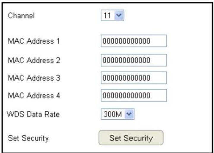
Configuring the router's wireless settings for WDS (Wireless Distribution System) mode.
Channel
Select a channel to assign to the wireless network. Valid values are from one to eleven in the US and one to thirteen in the EU.
MAC Address [#]
Enter the MAC address(es) for the wireless access point(s) that are part of the WDS.
WDS Data Rate
Select the data rate for the WDS.
Set Security
Click Set Security to set up the WDS security settings screen.
WDS Security Settings Screen
Selecting the type of WDS encryption (Disable, WEP or WPA Pre-Shared Key) for the wireless network.
Wired Equivalent Privacy (WEP)
Key Length
Select between 64-bit and 128-encryption.
Key Format
Select the type of characters used for the WEP Key: ASCII (5 characters) or Hexadecimal (10 characters).
Default Key
Select the default encryption key for wireless transactions.
Encryption Key [#]
Enter the encryption key(s) used to encrypt the data packets during data transmission.

Chapter 5
Wireless Encryption

natural_image
Exterior view of a circular electronic device labeled 'EnGenius' with control buttons (no readable text beyond branding)Wi-Fi Protected Access (WPA) Pre-Shared Key
WPA Type
Select the type of WPA.
- WPA Temporal Key Integrity Protocol (TKIP): Generates a 128-bit key for each packet.
- WPA2 Advanced Encryption Standard (AES): Government standard packet encryption which is stronger than TKIP.

Pre-Shared Key Type
Select the type of pre-shared key as Passphrase (ASCII) or Hexadecimal.
Pre-Shared Key
Enter the pre-shared Key value.
Configuring Security
Enabling security options on the wireless network to prevent intrusions to systems on the wireless network.
To view the Security settings, click Wireless then select
Security.
SSID Selection
Select the wireless network group in which you wish to change its wireless security settings.
Broadcast SSID
Enable or disable broadcast SSID. Choose whether or not the wireless group is visible to other members.
Wi-Fi Multimedia (WMM)
Enable or disable quality of server (QoS) to optimize the streaming for bandwidth sensitive data such as HDTV video streaming, online gaming, VoIP, videoconferencing, and etc.
Encryption
Select the encryption type for the router.
Enable 802.1x Authentication
Enable or disable 802.1x authentication.

Encryption Type
Enabling encryption is strongly encouraged because unauthorized parties within range of your router's wireless signal may attempt to access your wireless network and then gain access to private information on devices on your network. It's highly recommended that you encrypt your router with WPA2 (AES) for optimal security and throughput performance. Always select a strong passphrase greater than 8 characters long and comprised of letters, numbers, and symbols. Please make note of the passphrase and keep it in a secure location somewhere in your home in case you need to retrieve it.

IMPORTANT! WPA2 (AES) offers much stronger security than WEP (Wired Equivalent Privacy) which has been and can be compromised.
Click Apply to save the settings or Cancel to discard the changes.
Wi-Fi Protected Access (WPA) Pre-Shared Key
WPA Type
Select the type of WPA from the following:
• WPA2 Advanced Encryption Standard (AES):
RECOMMENDED – Government standard packet encryption which is stronger than TKIP.
- WPA Temporal Key Integrity Protocol (TKIP): Generates a 128-bit key for each packet.
- WPA2 Mixed: Mixed mode allows client devices to first associate to the router using WPA2, and if they fail to connect, then they are connected via WPA (TKIP).
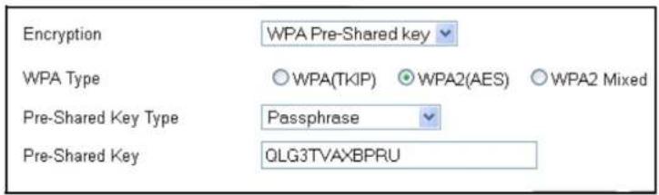
Pre-Shared Key Type
Select the type of pre-shared key as Passphrase (ASCII) or Hexadecimal.
Pre-Shared Key
Enter the Pre-sShared Key value.
WPA RADIUS
Using a RADIUS server to authenticate wireless stations and provide a session key to encrypt data during communications.
WPA Type
Select the type of Wireless Protected Access (WPA) from the following:
• WPA2 Advanced Encryption Standard (AES):
RECOMMENDED – Government standard packet encryption which is stronger than TKIP.
- WPA Temporal Key Integrity Protocol (TKIP): Generates a 128-bit key for each packet.
- WPA2 Mixed: Mixed mode allows client devices to first associate to the router using WPA2, and if they fail to connect, then they are connected via WPA (TKIP).
RADIUS Server IP Address
Enter the IP address of the server.
RADIUS Server Port
Enter the port number of the server.
RADIUS Server Password
Enter the password of the server.

Wired Equivalent Privacy (WEP)
Authentication Type
Select the type of authentication from the following:
- Open System: Wireless stations can associate with the router without WEP encryption
- Shared Key: Devices must provide the corresponding WEP key(s) when connecting to the router
- Auto: The router automatically detects whether Open System or Shared Key is being used
Key Length
Select between 64-bit and 128-encryption.
Key Type
Select the type of characters used for the WEP Key: ASCII (5 characters) or Hexadecimal (10 characters).
Encryption Key [#]
Enter the encryption key(s) used to encrypt the data packets during data transmission.
Enable 802.1x Authentication
Enable or disable 802.1x authentication.

Configuring Filters

WARNING! Incorrectly changing these settings may cause the device to stop functioning. Do not modify the settings in this section without a thorough understanding of the parameters.
When Enable Wireless Access Control is selected, only wireless clients with MAC addresses listed in the table are allowed to connect to the wireless network.
To view the Filter settings, click Wireless then select Filter.
Enabling Wireless Access Control
Select "Enable Wireless Access Control"
Description
Enter a description of the device allowed to connect to the network.
MAC Address
Enter the MAC Address of the wireless device.
Click Add to append a new device to the list or Reset to discard changes.

MAC Address Filtering Table
No. (Number)
The sequence number of the device.
Description
The description of the device.
MAC Address
The MAC address of the device.
Select
Indicates the device(s) that can have actions performed on them.
Click Delete Selected to remove selected devices from the list.
Click Delete All to remove all devices from the list.
Click Reset to discard changes. Click Apply to save the settings or Cancel to discard changes.

Configuring Wi-Fi Protected Setup
Wi-Fi Protected Setup (WPS) is an quick and easy way to associate a new wireless client device to the encrypted router using a PIN or the WPS buttons on each device.
To view the WPS settings, click Wireless then select WPS.
WPS
Enable or disable WPS.
WPS Current Status
Displays whether or not the wireless security is configured.
Self Pin Code
An 8-digit PIN which is required when configuring the router for the first time in Windows 7 or Vista.
SSID
The name of the wireless network.
Authentication Mode
The current security settings for the corresponding SSID (wireless network).
Passphrase Key
A randomly generated key created by the router during the WPS process.

WPS via Push Button
Click "Start to Process" to activate WPS.
WPS via PIN
Enter the PIN of a wireless device click "Start to Process" to activate WPS.
Configuring Client List
View the wireless devices currently connected to the router.
To view the Client List settings, click Wireless then select Client List.
Interface
The type of network connected to the device.
MAC Address
The MAC address of device connected to network.
Signal
The signal strength of the device connected to the network.
Idle Time
The amount of time the connected device has not been active on the network.
Click Refresh to refill the list with currently connected devices.
| WLAN Client Table | |||
| Interface | MAC Address | Signal (%) | Idle Time |
| Windows8test | 54:26:96:17:07:24 | 42 | 2 secs |
| Windows8test | 88 DC:96:01:4F:27 | 76 | 0 secs |
| Refresh | |||
Chapter 6
Advanced Settings
natural_image
Exterior view of a white EnGenius branded circular device with control buttons (no readable text or symbols beyond branding)Configuring Advanced Settings
Allows you to define the Advanced Settings available on the router.

WARNING! Incorrectly changing these settings may cause the device to stop functioning. Do not modify the settings in this section without a thorough understanding of the parameters.
To view the Advanced settings, click Wireless then select Advanced.
Fragment Threshold
Enter the maximum size of a packet during data transmission. A value too low could lead to low performance.
RTS Threshold
Enter the RTS threshold. If the packet size is smaller than the RTS threshold, the router does not use RTS/CTS to send the data packet.
Beacon Interval
Enter the beacon interval. This is the amount of time that the router sets to synchronize the network.
Delivery Traffic Indication Message (DTIM) Period
Enter the DTIM period. The DTIM is a countdown period informing clients of the next point of broadcast and multicast of messages over the network. Valid values are between 1 and 255.

N Data Rate
Select the N data rate. This is the rate in which the ESR Series Router will transmit data packets to wireless N compatible devices.
Channel Bandwidth
Select the channel bandwidth. The factory default is Auto 20/40MHz. The default setting provides the best performance by auto selecting channel bandwidth.
Preamble Type
Select the preamble type. Long Preamble provides better LAN compatibility and Short Preamble provides better wireless performance.
CTS Protection
Select the type of CTS protection. Using CTS Protection can lower the data collisions between Wireless B (802.11b) and Wireless G (802.11g) devices and lower data throughput.
Tx Power
Select the wireless signal strength level. Valid values are between 25% and 100%.
Click Apply to save the settings or Cancel to discard changes.
Setting Up Parental Controls
Offensive web content can be blocked when a parent specifies keywords. Parents can also limit Internet access within a specified time and day, with a Schedule. A Policy is a rule profile which describes the keyword filter and Internet access schedule. Parents can apply the policy to multiple users or Policy Members. The Parental Controls tool will screen policy members based on applied policies.
Configuring the Access Control List
To view the ACL settings, click Firewall then select ACL.

Note: By default, everyone is allowed to view all the contents without any limitation and filter.
Viewing the Access Control List
To learn how to view existing access control list, refer to Viewing Parental Policies.
Adding a Control Policy
To learn how to create and add a policy to the access control list, refer to Adding a Control Policy.
To view the Wizard settings,
click Parental Control then select Wizard.
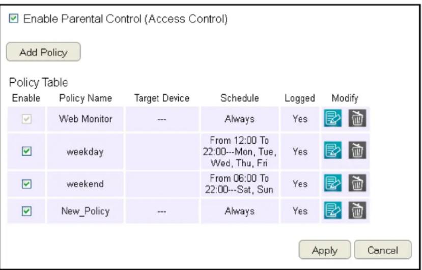
Enable Parental Control (Access Control)
Click to enable Parental Control.
Add Policy
Click the button to add a new control policy to the network.
Policy Table
Shows the control policies available on the network.
Click Apply to save changes or Cancel to discard them.
Adding a Control Policy
The router provides a wizard to guide you through setting up a new Access Control Policy.
To start the procedure, click the Add Policy button.

Click Next to continue the procedure or Cancel to stop the procedure.
The procedure consists of the following steps:
- Enter a unique name for your policy in the Policy Name text field.

- Click Prev to return to the previous screen, Next to continue the procedure, or Cancel to stop the procedure.
- Add target devices to the access control policy.
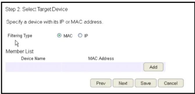
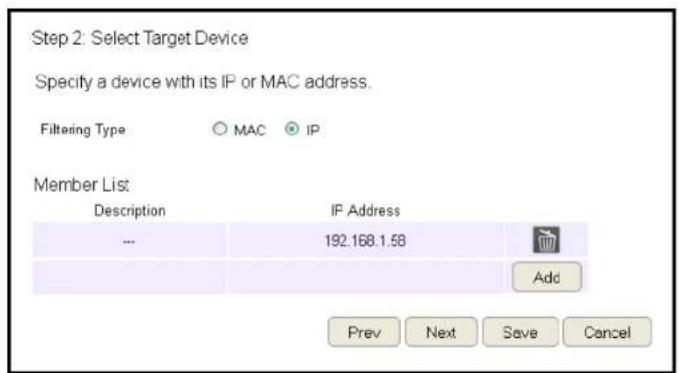
To add a device to the Member List, follow these steps:
a. Click MAC or IP from the Filter Type option.
b. Click Add to show the add client dialog.
c. Enter the name of the device in the Device Name text field.

d. Enter either a MAC address or an IP address in the Address field depending upon which filter type you chose.
e. Click the Add Device Button + to close the screen and add the device to the Member List.
-
Click Prev to return to the previous screen, Next to continue the procedure, Save to save the changes, or Cancel to stop the procedure.
-
Setting up a schedule for the router services.
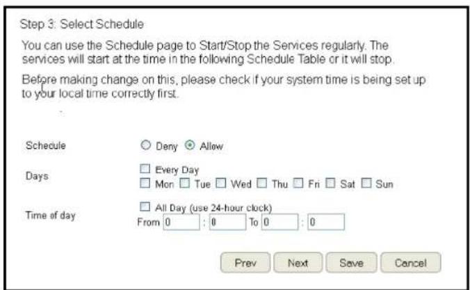
To set up a Service Schedule, follow these steps:
a. Select Allow from the Schedule option.
b. Click the days that the schedule will be active.
c. Enter the time period that the schedule will be active.
-
Click Prev to return to the previous screen, Next to continue the procedure, Save to save the changes, or Cancel to stop the procedure.
-
Setup a keyword and URL filter list.
Step 4: Web/Keyword Filter
You can block access to certain Web sites for a particular PC by entering either a full URL address or just a keyword of the Web site
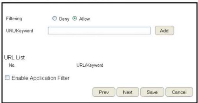
To set up a keyword/URL filter list, follow these steps:
a. Select Allow from the Filtering option.
b. Enter a keyword or URL in the URL/Keyword text field.
c. Click the Add button to add the filter to the list.
d. Repeat steps a through c for each filter.
- Click Enable Application Filter to filter software applications.
-
Click Prev to return to the previous screen, Next to continue the procedure, Save to save the changes, or Cancel to stop the procedure.
-
Select Enable to save web access information to a log file or Disable to ignore the information.

- Click Prev to return to the previous screen, Save to save the changes, or Cancel to stop the procedure.
Viewing Parental Policies
Available parental control policies are shown in a table and each policy can be enabled or disabled, edited, and deleted.
To view the Web settings, click Parental Control then select Web Monitor.
Enable
Click to enable or disable the control policy.
Policy Name
Shows the control policy name.
Target Device
Shows the target device MAC address or IP address.
Schedule
Shows the control policy schedule.
Logged
Shows whether the control policy is storing log information.
Modify
Edit a policy by clicking the Edit Button.

Delete a policy by clicking the Delete Button.


Guest Network
The Guest Network function enables you to offer Internet connectivity to visitors or guests while keeping other networked devices (computers and hard drives) and sensitive personal or company information private and secure.
The Guest Network is controlled by the Wireless SSID function. When the Guest Network function is enabled, the Guest SSID can only get the internet connection from WAN, but can not reach the client from the LAN port.
Enabling the Guest Network
To view the Selection settings, click Guest Network then select Selection.
Guest Network
Enable or Disable the Guest Network function
Client Isolation
Guest clients are isolated and cannot communicate with each other.
SSID
Choose a SSID for the Guest Network
used. The SSID can be defined from the Wireless setting page.
Wireless 2.4GHz
Guest Network
SSID
Wireless 5GHz
Guest Network
SSID
Disabled
esr600
Disabled
EnGeniusFD8C6B
Apply
Cancel
Click Apply to save the settings or Cancel to discard changes.
Configuring the DHCP Server Setting
The Guest Network SSID should be on a different subnet from the router's DHCP server.
To view the DHCP Server Settings, click Guest Network then select DHCP Server Setting.
Router IP address
Define the router IP address for the Guest network.
Default Subnet Mask
Define the Subnet Mask IP address for the Guest network.
Router IP Address
192.168.169.1
Default Subnet Mask
255.255.255.0
Start IP
192.168.169.100
End IP
192.168.169.200
Apply
Cancel
Start IP
To define the Guest network DHCP server start IP.
End IP
To define the Guest network DHCP server end IP.
Click Apply to save the settings or Cancel to discard changes.
Viewing the DHCP Client List on the Guest Network
Shows the list of guest clients registered on the network.
To view the DHCP Client List settings, click Guest Network then select DHCP Client List.
DHCP Client Table
Shows the IP address, MAC address, and expiration time of each of the registered clients on the list.
DHCP Client Table
IP Address
MAC Address
Expiration Time
No DHCP.
Refresh
IP Address
The IP address of the guest client.
MAC Address
The MAC address of the guest client.
Expiration Time
The time that the guest client's DHCP address will expire and must be renewed.
Click Refresh to refresh the view of the list.
IPv6
There are several connection types to choose from: Auto Detection, Static IPv6, Autoconfiguration (SLAAC/DHCPv6), PPPoE, IPv6 in IPv4 Tunnel, 6to4, and Link-local. If you are unsure of your connection method, please contact your IPv6 Internet Service Provider.

Note: If you are using the PPPoE option, you will need to ensure that any PPPoE client software on your computers has been removed or disabled.
Enabling IPv6 Settings
To view the Basic settings, click IPv6 then select Basic.
Before using or configuring the IPv6 protocol, or IPv6 passthrough, on an ESR Series Router you must enable it.
IPv6
Select enable to configure the IPv6 protocol on the router.
IPv6 Passthrough
Select enable to allow IPv6 passthrough functionality.
IPv6 must be disabled to enable this feature.
Click Apply to save the settings or Cancel to discard changes.

Viewing the IPv6 Connection Status
To view the Status information, click IPv6 then select Status.
IPv6 Connection Information
Shows the IPv6 connection type, the LAN IPv6 link-local address and the DHCP-PD.
LAN IPv6 Computers List
Shows a list of network computers and their IPv6 connection information.
IPv6 Connection Information
IPv6 Connection Type Link-local only
LAN IPv6 Link-Local Address FE80::202:6FFF:FEFB:A016
DHCP-PD Disabled
LAN IPv6 Computers
Name (if any)
MAC
IPv6 Address
Configuring Static IPv6
To view the Static IPv6 settings, click IPv6 then select Static IPv6.
Use Link-Local Address
Enable or disable LAN link-local address.
IPv6 Address
Enter the LAN (local) IPv6 address for the router.
Subnet Prefix Length
Enter the subnet prefix length.
Default Gateway
Enter the default gateway.
Primary IPv6 DNS Address
Enter the primary IPv6 DNS address.
Secondary IPv6 DNS Address
Enter the secondary IPv6 DNS address.
LAN IPv6 Address
Enter the LAN IPv6 address.
LAN IPv6 Link-Local Address
Enter the LAN IPv6 link-local address.
Enable Automatic IPv6 Address Assignment
Enable or disable automatic IPv6 address assignment.
Autoconfiguration Type
Enter the autoconfiguration type. (Default: SLAAC+RDNSS).
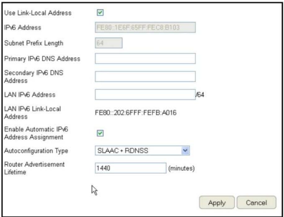
Router Advertisement Lifetime
Enter the IPv6 Address Lifetime (in minutes).
Click Apply to save the settings or Cancel to discard changes.
Setting Autoconfiguration
To view the Auto Configuration settings, click IPv6 then select Auto Configuration.
Obtain A DNS Server Address Automatically
Enable or disable obtaining a DNS server automatically.
Primary IPv6 DNS Address
Enter the primary IPv6 DNS address.
Secondary IPv6 DNS Address
Enter the secondary IPv6 DNS address.
Enable DHCP-PD
Enable or disable DHCP-prefix delegation (PD).
LAN IPv6 Address
Enter the LAN IPv6 address.
LAN IPv6 Link-Local Address
Enter the LAN IPv6 link-local address.
Enable Automatic IPv6 Address Assignment
Enable or disable automatic IPv6 address assignment.
Autoconfiguration Type
Enter the autoconfiguration type. (Default: SLAAC+RDNSS)
Router Advertisement Lifetime
Enter the IPv6 Address Lifetime (in minutes).
Click Apply to save the settings or Cancel to discard changes.

Configuring PPPoE
To view the PPPoE settings, click IPv6 then select PPPoE.
Address Mode
Select Static if your ISP assigned you the IP address, subnet mask, gateway, and DNS server addresses. In most cases, select Dynamic.
IP Address
Enter the IP address (Static PPPoE only).
User Name
Enter your PPPoE user name.
Password
Enter your PPPoE password.
Verify Password
Retype the your PPPoE password.
Service Name
Enter the ISP Service Name (optional).
Reconnect Mode
Select either Always-on, On-Demand, or Manual.
Maximum Idle Time
Enter a maximum idle time during which the Internet connection is maintained during inactivity. To disable this feature, enable Auto-reconnect.
MTU
Maximum Transmission Unit - you may need to change the MTU for optimal performance with your specific ISP. 1492 is the default MTU.
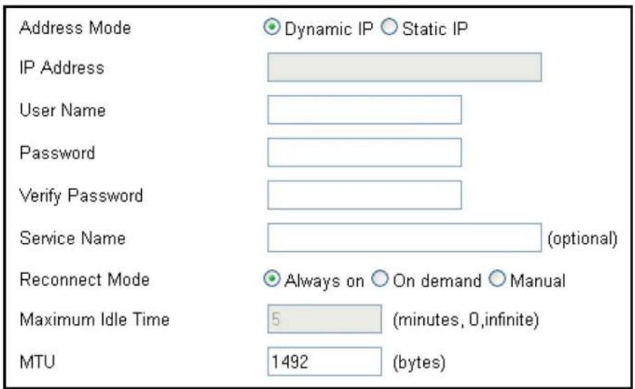
Obtain A DNS Server Address Automatically
Enable or disable obtaining a DNS server automatically.
Primary IPv6 DNS Address
Enter the primary IPv6 DNS address.
Secondary IPv6 DNS Address
Enter the secondary IPv6 DNS address.
Enable DHCP-PD
Enable or disable DHCP-prefix delegation (PD).
LAN IPv6 Address
Enter the LAN IPv6 address.
LAN IPv6 Link-Local Address
Enter the LAN IPv6 link-local address.
Enable Automatic IPv6 Address Assignment
Enable or disable automatic IPv6 address assignment.
Autoconfiguration Type
Enter the autoconfiguration type. (Default: SLAAC+RDNSS)
Router Advertisement Lifetime
Enter the IPv6 Address Lifetime (in minutes).
Click Apply to save the settings or Cancel to discard changes.

Configuring 6to4
To view the 6to4 settings, click IPv6 then select 6to4.
6to4 Address
Enter the 6to4 IP address.
Primary IPv6 DNS Address
Enter the primary IPv6 DNS address.
Secondary IPv6 DNS Address
Enter the secondary IPv6 DNS address.
LAN IPv6 Address
Enter the LAN IPv6 address.
LAN IPv6 Link-Local Address
Enter the LAN IPv6 link-local address.
Enable Automatic IPv6 Address Assignment
Enable or disable automatic IPv6 address assignment.

Autoconfiguration Type
Enter the autoconfiguration type. (Default: SLAAC+RDNSS)
Router Advertisement Lifetime
Enter the IPv6 Address Lifetime (in minutes).
Click Apply to save the settings or Cancel to discard changes.
Viewing Local Connections
To view the Link Local settings, click IPv6 then select Link Local.
LAN IPv6 Link-Local Address
Enter the LAN IPv6 link-local address.
Click Apply to save the settings or Cancel to discard changes.
LAN IPv6 Link-Local Address
FE80::202:6FFF:FEFB:A016
Apply
Cancel
Firewall Setup

Note: This section applies to Client Router mode.
Configuring Basic Settings
To view the Basic settings, click Firewall then select Basic.
The ESR Series Router firewall automatically detects and blocks Denial of Service (DoS) attacks. URL blocking, packet filtering and stateful packet inspection (SPI) are also supported. The details of the attack and the timestamp are recorded in the security log.
Firewall
Enable or disable the firewall of the ESR Series Router.
Click Apply to save the settings or Cancel to discard changes.
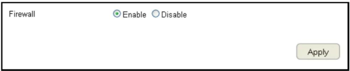
Configuring Advanced Settings
The router supports VPN pass-through which allows virtual private networking (VPN) packets to pass through the firewall. To view the Advanced settings, click Firewall then select Advanced.

Note: VPN L2TP Pass-through, VPN PPTP Pass-through, and VPN IPSec Pass-through are enabled by factory default.
VPN L2TP Pass-through
Click Select to allow an L2TP connection method over a VPN.
VPN PPTP Pass-through
Click Select to allow a PPTP connection method over a VPN.
| Description | Select |
| VPN L2TP Pass-Through | ☑ |
| VPN PPTP Pass-Through | ☑ |
| VPN IPSec Pass-Through | ☑ |
| PPPoE Pass-Through | ☐ |
| Apply Cancel |
VPN IPSec Pass-through
Click Select to allow an IPSec connection method over a VPN.
IPv6 Pass-through
Click Select to allow IPv6 packets to pass through the firewall.
PPPoE Pass-through
Click Select to allow a PPPoE packets to pass through the firewall.
Click Apply to save the settings or Cancel to discard changes.
VPN L2TP Pass-through Click Select to allow an L2TP connection method over a VPN.
VPN PPTP Pass-through Click Select to allow a PPTP connection method over a VPN.
VPN IPSec Pass-through Click Select to allow an IPSec connection method over a VPN.
IPv6 Pass-through Click Select to allow IPv6 packets to pass through the firewall.
PPPoE Pass-through Click Select to allow PPPoE packets to pass through the firewall.
| Description | Select |
| VPN L2TP Pass-Through | |
| VPN PPTP Pass-Through | |
| VPN IPSec Pass-Through | |
| IPv6 Pass-Through | |
| PPPoE Pass-Through |

Click Apply to save the settings or Cancel to discard changes.

Note: VPN L2TP Pass-through, VPN PPTP Pass-through, and VPN IPSec Pass-through are enabled by factory default.
Configuring Demilitarized Zone
Configuring a device on the LAN as a Demilitarized Zone (DMZ) host allows unrestricted two-way Internet access for Internet applications, such as online video games, to run from behind the NAT firewall. The DMZ function allows the router to redirect all packets going to the WAN port IP address to a particular IP address on the LAN. The difference between the virtual server and the DMZ function is that a virtual server redirects a particular service or Internet application, such as FTP, to a particular LAN client or server, whereas a DMZ redirects all packets, regardless of the service, going to the WAN IP address to a particular LAN client or server. A DMZ host allows a computer to have all its connections and ports completely open during data transmission.

WARNING! The PC defined as a DMZ host is not protected by the firewall and is vulnerable to malicious network attacks. Do not store or manage sensitive information on the DMZ host.
To view the DMZ settings, click Firewall then select DMZ.
Enabling DMZ
Click Enable DMZ to activate DMZ functionality.
Local IP Address
Enter an IP address of a device on the LAN.

Click Apply to save the settings or Cancel to discard changes.
Configuring Denial of Service
To enable blocking of denial of service (DoS) attacks, select the DoS option in the Firewall section. DoS attacks can flood the Internet connection with the continuous transmission of data. Blocking these attacks ensures that the Internet connection is always available.
To view the DoS settings, click Firewall then select DoS.
Block DoS
Enable or disable blocking DoS attacks.
Discard Ping on WAN
ICMP (ping) packages are blocked while Block DoS is enabled.
Block DoS
Discard Ping on WAN
Enable
Disable
Enable
Disable
Apply
Cancel
Enable Discard Ping on WAN if the WAN port is required.
Click Apply to save the settings or Cancel to discard changes.
Virtual Private Network Setup
A Virtual Private Network (VPN) provides a secure connection between two remote locations or two users over the Internet. It provides authentication to securely encrypt data communicated between the two remote endpoints. The Short Model Name supports up to 5 VPN tunnels, making it ideal for small-office / home-office users or employees who work from home but need to communicate securely back to the main office.
Viewing Status
To view the Status settings, click VPN then select Status.
No. (Number)
The sequence number of the VPN tunnel.
Name
The name of the VPN tunnel.
Type
The type of VPN tunnel.
Gateway/Peer IP Address
The VPN gateway or peer IP address.
Transmit Packets
The number of packets transmitted.
Received Packets
The number of packets received.
Uptime
The amount of time the VPN has been active.
Select
Indicates the device(s) that can have actions performed on them.

Configuring a VPN Tunnel Profile
To view the Status settings, click VPN then select Status. Manually configure a VPN tunnel profile.
Creating a Profile
- Click Add to create a new VPN tunnel profile.
- Click Edit to edit the settings of the selected profile.
- Click Delete Selected to delete the selected profile.
- Click Delete All to delete all current profiles.

General
For manually configuring a VPN tunnel profile.
Name: Enter the name for this profile.
Connection Type: Click the drop-down menu to select the connection type (PPTP, L2TP, IPSec, L2TP over IPSec).
Authentication Type: Click the drop-down menu to select the authentication type.
Shared Key: Enter the shared key to be used for this profile.
Confirm: Enter the shared key a second time to confirm the shared key.
Local ID Type: Click the drop-down menu to select the type of ID used for this profile (IP address, Domain Name, Email Address).
Local ID: Enter the local ID designation based on definition type from Local ID Type, previous field.
Peer ID type: Click the drop-down menu to select the type of Peer ID for this profile (IP address, Domain Name, Email Address).
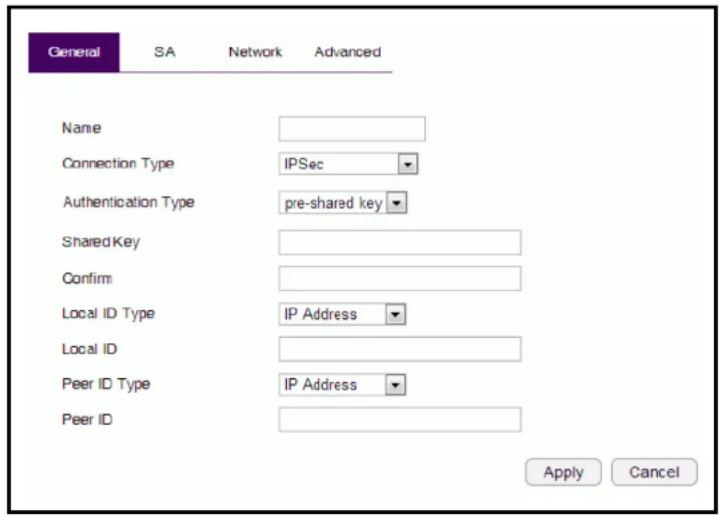
Peer ID: Enter the Peer ID designation based on definition type from Peer ID Type, previous field.
Apply: Click Apply to save the changes.
Cancel: Click Cancel to delete the changes.
SA (Security Association)
IKE (Internet Key Exchange) is configured in two negotiations. Phase 1 authenticates the VPN Clients to each other by confirming the matching Pre-Shared Key with the two gateways. IPSec is the Phase 2 of the VPN process.
Manually configuring a VPN tunnel profile.
IKE (Phase 1) Proposal
Exchange: Click the drop-down menu to select the type of exchange (Main Mode, Aggressive Mode).
DH Group: Click the drop-down menu to select the DH group (group 1, group 2, group 5, group 14).
Encryption: Click the drop-down menu to select the type of encryption (DES, 3DES, AES128, AES192, AES256).
Authentication: Click the drop-down menu to select the authentication protocol (MD5, SHA1).
Life Time: Enter the life time value for Phase 1. The life time value should be greater than Phase 2 (IPSec). 86400 sec. (1day) is a common default and is a normal value for Phase 1.
IPSec (Phase 2) Proposal
Protocol: Click the drop-down menu to select the protocol type (ESP, AH)
Encryption: Click the drop-down menu to select the type of encryption (DES, 3DES, AES128, AES192, AES256).

Authentication: Click the drop-down menu to select the authentication protocol (MD5, SHA1).
Perfect Forward Secrecy (PFS): Select enable to enable PFS. A fresh DH key is generated during IKE phase II and renewed for each key exchange to eliminate dependencies between the keys.
DH Group: Click the drop-down menu to select the DH group (group 1, group 2, group 5, group 14).
Life Time: Enter the life time value for Phase 2. The life time value should be smaller than Phase 1 (IKE). 3600 sec. (1 hour) is a common value for Phase 2.
Apply: Click Apply to save the changes.
Cancel: Click Cancel to delete the changes.
Network
Manually configuring a VPN tunnel profile.
Security Gateway Type: Click the drop-down menu to select the Security Gateway Type (IP Address, Domain Name)
Security Gateway: Enter the gateway value as defined in Security Gateway Type.
Local Network
Local Address: Enter the IP address of the local PC.
Local Netmask: Enter the netmaks of the local PC.
Remote Network
Remote Address: Enter the IP address of the remote PC.
Remote Netmask: Enter the netmask of the remote PC.
Apply: Click Apply to save the changes.
Cancel: Click Cancel to delete the changes.

Advanced
Manually configuring a VPN tunnel profile.
NAT Traversal: Select enable to enable the NAT Traversal function in order to hide the private IP address from public view.

Note: Services such as VoIP require the use of a private IP address.
Dead Peer Detection:
Apply: Click Apply to save the changes.
Cancel: Click Cancel to delete the changes.

Configuring a User Setting
The User Setting function allows you to create user profiles inorder to setup login access to the VPN service.
Name
Enter the name of the new user profile.
Password
Enter the password for the user name.
Confirm
Enter the password a second time to confirm the setting.
Add
Click Add to accept the profile and add it to the Current VPN User Table.
Reset
Click Reset to clear the new settings.
Current VPN User Table
Displays the User ID, User Name and Selection status.
Delete Selected
Click to delete the selected user profile.
Delete All
Click to delete all the current user profiles.

Reset
Click to clear the selections from the Current VPN User Table.
Apply
Click to accept save the new settings.
Cancel
Click to clear the new changes.
USB Port
The ESR1750 router is equipped with a USB port for connecting a hard drive so media content can be accessed or transferred to other devices in the home or devices away from home.
Viewing EnShare
The EnShare feature allows you to access media content stored on a USB hard drive connected to the router's USB port in the home and when you are away from home when you have access to the Internet.
By default the EnShare feature is enabled.
EnShare Remote Access

nable

sable
Apply
To view the EnShare settings or disable EnShare, click USB Port then select EnShare.
- Select Disable to disable the EnShare feature.
- Click Apply to save the new settings.
File Sharing
The File Sharing function allows you to provide users the ability to share files over the network through the Samba service. By default the EnShare feature is enabled.
Samba Service

nable

Disable
Apply
Cancel
To view the File Sharing settings, click USB Port then select File Sharing.
- Select Enable to enable the Samba Service function.
- Click Apply to save the new settings, or click Cancel to delete the changes.
Viewing File Server
The File Server function allows you to provide network users FTP access to shared USB stored files.
To view the File Server settings, click USB Port then select File Server.
Enable FTP Service
Select this to enable the FTP service to share files on the USB device
Port Number
Define the port number (default: 21) to open for the FTP service.
Login Timeout
Define the period of inactivity (default: 90) before a user is logged out.
Stay Timeout
Define the lockout period (default: 90) before a user is allowed to attempt a login.
Login User
Define the number of concurrent users to access the service (Max: 20 users)
Share Mode
Define the type of share privilege: Read/Write, Read only.
Use Anonymous Login
Select this to allow anonymous user login.
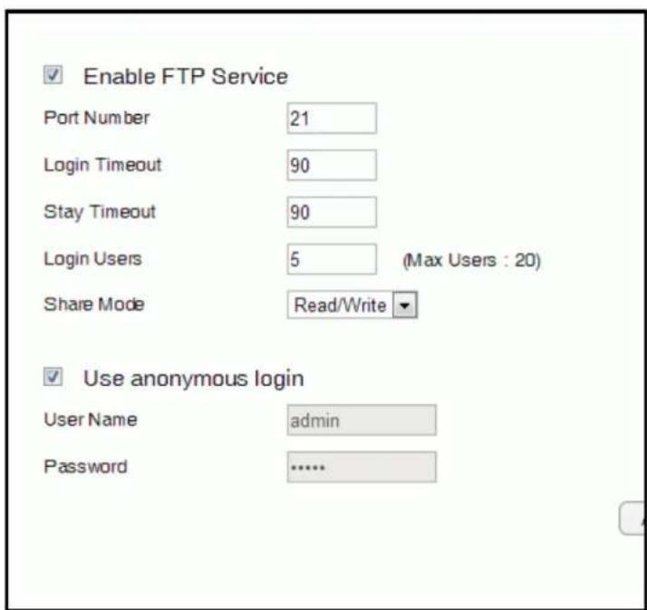
User Name
Enter the user name to login to the FTP service.
Password
Enter the password to login to the FTP service.
Viewing DLNA
The DLNA Media Server function allows you to transfer photos, music and video between networked devices through the ESR Series Router.
To view the DLNA settings, click USB Port then select DLNA.
- Select Enable to enable the DLNA Media Server function.
- In the Share Folder Name, enter the name of the shared folder.
- Click Apply to save the new settings, or Cancel to clear the changes.

Advanced Network Settings
NAT Setup
Network Address Translation (NAT) allows users on the LAN to access the Internet through a single Public IP Address or multiple Public IP Addresses. NAT provides firewall protection from hacker attacks and allows for mapping LAN IP addresses to WAN IP addresses with key services such as websites, FTP, and video game servers.
To view the NAT settings, click Advanced then select NAT.
NAT
Enable or Disable the NAT.
Network Turbine
Enable or Disable the network turbine.


Note: The network turbine is designed to improve the router's performance. There is about 20\~30% improvement when the network turbine is enabled.

Note: The network turbine may cause problems with the Internet connection. Disable the network turbine function if you experience connection issues.
Click Apply to save the settings or Cancel to discard changes.
Port Mapping Setup
Port Mapping allows you to redirect a particular range of service port numbers from the WAN to a particular LAN IP address.
To view the Port Mapping settings, click Advanced then select Port Mapping.
Enable Port Mapping
Click Enable Port Mapping to activate port mapping.
Description
Enter notes or details about the mapped port range configuration.
Local IP
Enter the local IP address of the server behind the NAT firewall.

Protocol
Select the protocol to use for mapping from the following: TCP, UDP or Both.
Port Range
Enter the range of ports to be forwarded.
Click Add to append a new device to the list or Reset to discard changes.
Current Port Mapping Table
Displays a list of mapped port ranges in use on the network.
No. (Number)
The sequence number of the mapped port range.
Description
Notes or details about the mapped port range.
Local IP
IP address of the server for the mapped port range.

Type
The protocol used to communicate with the WAN ports and LAN server.
Port Range
The range of mapped ports.
Select
Indicates the device(s) that can have actions performed on them.
Click Delete Selected to remove selected devices from the list.
Click Delete All to remove all devices form the list.
Click Reset the discard changes.
Click Apply to save the settings or Cancel to discard changes.
Port Forwarding Setup
Port forwarding enables multiple server applications on a LAN to serve clients on a WAN over a single WAN IP address. The router accepts incoming client packets, filters them based on the destination WAN, or public, port and protocol and forwards the packets to the appropriate LAN, or local, port. Unlike the DMZ feature, port forwarding protects LAN devices behind the firewall.
To view the Port Forwardung settings, click Advanced then select Port Forwarding.
Enable Port Forwarding
Click Enable Port Forwarding to active port forwarding.
Description
Enter notes or details about the forwarded port configuration.
Local IP
Enter the local IP address of the server behind the NAT firewall.
Protocol
Select the protocol to use for mapping from the following: TCP, UDP or Both.
Local Port
Enter the LAN port number that WAN client packets will be forward to.
Public Port
Enter the WAN port number that clients will send their packets to.
Click Add to append a new configuration to the table or Reset to discard changes.
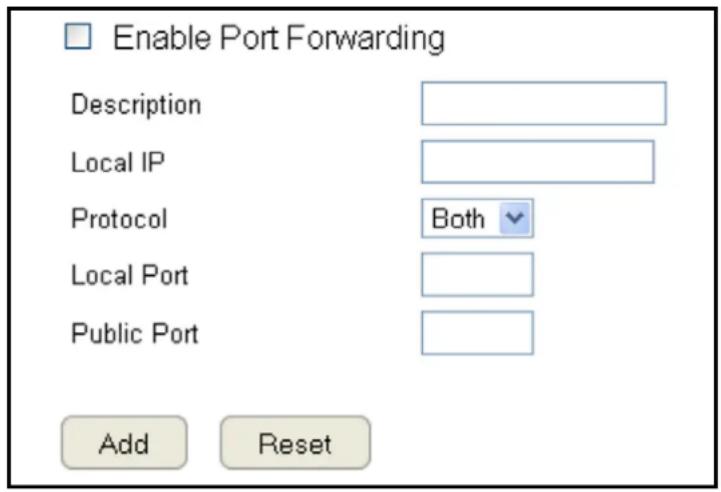
Current Port Forwarding Table
The table of current port forwarding configurations.
Click Delete Selected to remove selected devices from the list.
Click Delete All to remove all devices form the list.
Click Reset the discard changes.
Click Apply to save the settings or Cancel to discard changes.

Port Triggering Setup
Some applications, such as online games, videoconferencing and VoIP telephony, require multiple ports for inbound and outbound traffic. If an application requires simultaneous use of incoming and an outgoing ports, configure port triggering to map a local port or range of ports to a specific public port. Sending packets out over the local port triggers the router to open an incoming local port that is mapped to the same public port and application as the outgoing local port(s). The local application can communicate over the incoming and outgoing ports without the need for creating a fixed address.
To view the Port Triggering settings, click Advanced then select Port Triggering.
Enable Port Triggering
Click Enable Trigger Port to activate port triggering.
Description
Enter notes or details about the port triggered configuration.
Popular Applications
Select a default application or add a new one.
Trigger Port
Enter the application's outbound port number(s).
Trigger Type
Select the protocol to use for port triggering from the following: TCP, UDP or Both.
Public Port
Enter the inbound port(s) for the application in the following format: 2300-2400 or 47624.
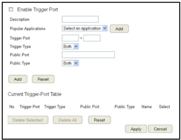
Public Type
Select the protocol to use for the inbound port from the following: TCP, UDP or Both.
Click Add to append a new configuration to the table or Reset to discard changes.
Current Port Triggering Table
The list of current port triggering configurations. Click Delete Selected to remove selected devices from the list.
Click Delete All to remove all devices form the list. Click Reset the discard changes.
Click Apply to save the settings or Cancel to discard changes.

Application Layer Gateway Setup
The ALG (Application Layer Gateway) serves as a window between correspondent application processes so that they may exchange information on an open environment.
To view the ALG settings, click Advanced then select ALG.
Select the listed applications that need ALG support and then the router will authorize them to pass through the NAT gateway.
Click Apply to save the settings or Cancel to discard changes.
| Description | Select |
| TFTP | □ |
| IPsec | □ |
| FTP | □ |
| SIP | □ |
| RTSP | □ |
| Apply Cancel |
Universal Plug and Play Setup
UPnP helps internet devices, such as gaming and videoconferencing, to access the network and connect to other registered UPnP devices.
To view the UPnP settings, click Advanced then select UPnP.
Click Enable or Disable to activate or deactivate UPnP.
Click Apply to save the settings or Cancel to discard changes.
UPnP

Enable

Disable
Apply
Cancel
Internet Group Multicast Protocol Setup
Internet Group Multicast Protocol (IGMP) is a network-layer protocol used to establish membership in a multicast group.
To view the IGMP settings, click Advanced then select IGMP.
Click Enable or Disable to activate or deactivate IGMP.
Click Apply to save the settings or Cancel to discard changes.

Note: Disabling the Multicast function may cause IP based multimedia devices, such as an IP-STB or OTT box, may lose connectivity with the media streaming server.
Quality of Service Setup
QoS can prioritize bandwidth use such as video streaming, online gaming, VoIP telephony and videoconferencing to ensure stable and efficient network performance.
To view the QoS settings, click Advanced then select QoS.
Total Bandwidth Settings
Uplink Select the maximum bandwidth speed for outbound traffic.
Downlink Select the maximum bandwidth speed for inbound traffic.
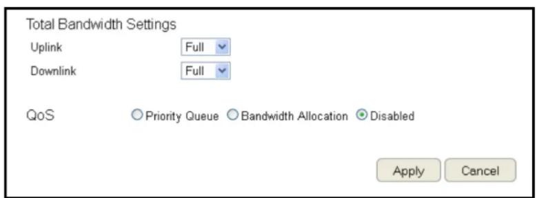
Note: Click Disabled if you do not want to prioritize any data or protocol.
Priority Queue
Set network resource usage based on specific protocols or port ranges. Incoming packets are processed based on the protocols' position within the queue.
Unlimited Priority Queue
Local IP Address
Enter the local IP address of a device on the network. This device's activity is not restricted by the QoS feature.
High/Low Priority Queue
Specify the priority for different protocols. Additional protocols and port ranges can be added.
Click Apply to save the settings or Cancel to discard changes.

Bandwidth Allocation
Set network resource usage, for inbound and outbound traffic, based on local IP and port ranges.
Type
Select Download or Upload to specific the direction of packet traffic.
Local IP Range
Enter the local IP range of the current configuration.
Protocol
Select the protocol to manage for the current configuration.
Port Range
Enter the local port range of the current configuration.
Policy
Select Min or Max to specify the type of configuration policy.
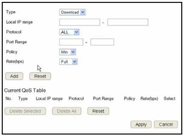
Rate (bps)
Select the bandwidth rate, in bits per second (bps), of the current configuration.
Click Add to save the settings and list the configuration in the Current QoS table or Reset the discard changes.
Click Apply to save the settings or Cancel to discard changes.
Routing Setup
Typically static routing does not need to be setup because the router has adequate routing information after it has been configured for Internet access. Static routing is only necessary if the router is connected to network under a different subnets.
To view the Routing settings, click Advanced then select Routing.

Note: To enable a static routing, NAT must be disabled. If the router is connected with a network under the different subnet, the routing setup allows the network connection within two different subnets.
Enable Static Routing
Click Enable Static Routing to activate the feature.
Destination LAN IP
Enter the LAN IP address of the destination device.
Subnet Mask
Enter the Subnet Mask of the destination device.
Default Gateway
Enter the default gateway IP address for the destination device.
Hops
Enter the maximum number of hops within the static routing that a packet is allowed to travel.
Interface
Select LAN or WAN as the interface.

Click Add to save the settings and list the configuration in the Current Static Routing table or Reset the discard changes.
View and select devices in the Current Static Routing Table.
Click Delete Selected or Delete All to remove devices from the table. Click Reset to stop.
Click Apply to save the settings or Cancel to discard changes.

Wake on LAN Setup
Wake on LAN setup (WOL) allows the administrator to activate a computer over the network.
To view the WOL settings, click Advanced then select WOL.
Enabling WOL over WAN
Click Enable WOL over WAN to activate the feature.
Server Port
Enter the server port of the device to activate.
Wake MAC Address
Enter the MAC address of the device to activate.
Click Start to activate the device.

Click Apply to save the settings or Cancel to discard changes.
Tools Setup
Configuring the Administrator Account
Change the router's system password as well as setup a device to remotely configure the settings.
To view the Admin settings, click Tools then select Admin.
- Login Name: Keep or change existing login name
- Old Password: Enter the existing administrator password
- New Password: Enter the new administrator password
- Repeat New Password: Re-type the new administrator password
• Graphical Authentication: To enable or disable CAPTCHA
Remote Management
- Host Address: Enter the designated host IP Address.
- Port: Enter the port number (Default: 8080) for remote accessing management web interface.
- Enable: Select to enable remote management.
Click Apply to save the settings or Cancel to discard changes.

Note: To access the settings of the ESR Series Router remotely, enter the router's WAN IP address and port number.


System Time Setting
Change the system time of the ESR Series Router and setup automatic updates through a network time (NTP) protocol server or through a computer.
To view the Time settings, click Tools then select Time.
Synchronizing with an NTP Server
Time Setup
Select how the ESR Series Router obtains the current time.
Time Zone
Select the time zone for the ESR Series Router.

NTP Time Server
Enter the domain name or IP address of an NTP server.
Enabling Daylight Savings
Click to enable or disable daylight savings time.
Start Time
Select the date and time when daylight savings time starts.
End Time
Select the date and time when daylight savings time ends.
Click Apply to save the settings or Cancel to discard changes.
Synchronizing Time with a Computer
Time Setup
Select how the ESR Series Router obtains the current time.
Computer Date and Time
Displays system date and time from a computer.
Enable Daylight Saving
Click to enable or disable daylight savings time.
Start Time
Select the date and time when daylights savings time starts.

End Time
Select the date and time when daylights savings time ends.
Click Apply to save the settings or Cancel to discard changes.
Dynamic Domain Name Service (DDNS) Setup
The most common use for DDNS is in allowing an Internet domain name to be assigned to a computer with a varying (dynamic) IP address. This makes it possible for other sites on the Internet to establish connections to the machine without needing to track the IP address themselves.
To view the DDNS settings, click Tools then select DDNS.
Dynamic DNS
Click to enable or disable DDNS.
Server Address
Select the server address.
Host Name
Enter the host name.
Username
Enter a username for the host service.
Password
Enter a password for the host service.
Click Apply to save the settings or Cancel to discard changes.

Diagnosis that Client Devices Are Connected to the Router
The diagnosis feature allows the administrator to verify that a client device is available on the network and is accepting request packets. If the ping result returns alive, it means a device is connected. This feature does not work if the target device is behind a firewall or has security software installed.
To view the Diagnosis settings, click Tools then select Diagnosis.
Diagnosing a Network Connection Problem
Address to Ping
Enter IP address of the device to ping.
Address to Ping
Ping Result
Start
Ping Frequency
Select the interval, in seconds, that the ping message is sent out.
Click Start to begin the diagnosis.
Upgrading The Router's Firmware
Firmware is the router's system software that operates and allows the administrator to interact with it.
To view the Firmware settings, click Tools then select Firmware.

WARNING! Upgrading firmware through a wireless connection is not recommended. Firmware upgrading must be performed while connected to an Ethernet (LAN port) with all other clients disconnected.
To update the firmware version, follow these steps:
- Download the appropriate firmware approved by EnGenius from an EnGenius web site. See the Downloads tab on the product page for this product. For new products, new firmware may not be readily available.
- Click Choose File.
- Browse the file system and select the firmware file.
- Click Apply.
You can upgrade the firmware of the router in this page. Ensure, the firmware you want to use is on the local hard drive of your computer. Click on Browse to browse and locate the firmware to be used for your update.

Apply
Cancel
Backing Up The Router's Settings
Save them as a configuration file on your computer.
To view the Back-up settings, click Tools then select Back-up.
Restoring to the router's Factory Default settings
Click Reset to restore the ESR Series Router to factory defaults.
Backup Settings
Click Save to save the current configuration on the router to a *.dlf file.
Restore Settings
To restore saved settings, do the following:
a. Click Choose File.
b. Browse the file system for location of the settings file (*.dlf).
c. Click Upload.

Rebooting the Router
This feature allows you to reboot the router in the event of a system hang up or other disruption to the network.
To view the Reset settings, click Tools then select Reset.
Click Apply to reset the device.
In the event the system stops responding correctly or stops functioning, you can perform a reset. Your settings will not be changed. To perform the reset, click on the APPLY button.
Apply
Appendix
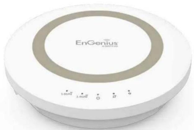
natural_image
Exterior view of a white EnGenius branded electronic device with circular design and control buttons (no readable text or symbols beyond branding)Wall Mounting The Router
The following are instructions if you choose to mount the router on a wall.

Note: Choose a location that is within reach of an electrical outlet for the AC adapter and the DSL or Cable modem.
To mount the device on the wall do the following:
- Measure the distance from the middle of each mounting screw hole.
- Mark the locations of the screw holes on the wall.
- Drill a hole for each marked location and insert a screw in each.

Note: Make sure to leave enough of the screw head above the wall surface to secure the router.
- Install and secure the mounts onto the router.
- Install the router on the wall.
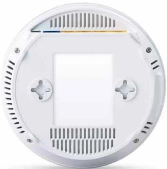
natural_image
Close-up of a white circular electronic device casing with ventilation grilles and mounting holes (no text or symbols visible)Federal Communication Commission Interference Statement
This equipment has been tested and found to comply with the limits for a Class B digital device, pursuant to Part 15 of the FCC Rules. These limits are designed to provide reasonable protection against harmful interference in a residential installation. This equipment generates uses and can radiate radio frequency energy and, if not installed and used in accordance with the instructions, may cause harmful interference to radio communications. However, there is no guarantee that interference will not occur in a particular installation. If this equipment does cause harmful interference to radio or television reception, which can be determined by turning the equipment off and on, the user is encouraged to try to correct the interference by one of the following measures:
- Reorient or relocate the receiving antenna.
- Increase the separation between the equipment and receiver.
- Connect the equipment into an outlet on a circuit different from that to which the receiver is connected.
- Consult the dealer or an experienced radio/TV technician for help.

WARNING! Any changes or modifications not expressly approved by the party responsible for compliance could void the user's authority to operate this equipment.
This device complies with Part 15 of the FCC Rules. Operation is subject to the following two conditions: (1) This device may not cause harmful interference, and (2) this device must accept any interference received, including interference that may cause undesired operation.

FCC Radiation Exposure Statement
Important: This equipment complies with FCC radiation exposure limits set forth for an uncontrolled environment. This device complies with FCC RF Exposure limits set forth for an uncontrolled environment, under 47 CFR 2.1093 paragraph (d)(2). This transmitter must not be co-located or operating in conjunction with any other antenna or transmitter.
Industry Canada Statement
This device complies with RSS-210 of the Industry Canada Rules. Operation is subject to the following two conditions: (1) This device may not cause harmful interference, and (2) this device must accept any interference received, including interference that may cause undesired operation.
Radiation Exposure Statement: This equipment complies with IC radiation exposure limits set forth for an uncontrolled environment.
This equipment should be installed and operated with minimum distance 20cm between the radiator & your body.
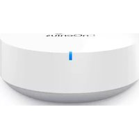
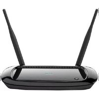
- IMPORTANT
- Table of Contents
- Chapter 1 Product Overview....5
- Chapter 2 Controlling the Router Through Its
- Web Configuration Interface....10
- Chapter 3 Installation Setup Wizard....27
- Chapter 4 Basic Network Settings....35
- Chapter 5 Wireless Encryption....65
- Chapter 6 Advanced Settings....75
- Appendix....132
- Chapter 1
- Product Overview
- Key Features
- Robust and Reliable Wireless Performance
- A Media Sharing Platform
- Industry-standard Wireless Security
- More Guest Access Options
- Technical Specifications
- Device Interface
- IEEE Standards
- LED Indicators
- Package Contents
- Power Specification
- Certifications
- Physical/Environmental Conditions
- Software Features
- Frequency Bands
- Operating Mode
- Wireless Features
- Security
- Physical Interface
- Chapter 2
- Controlling the Router Through Its Web Configuration Interface
- Logging In
- Viewing the Web Configuration Dash Board
- Home Page
- Home
- Setup Wizard
- Network Settings
- USB Storage Sharing
- IP Cam Viewer
- Language
- Logout
- Web Menus Overview
- System
- Operation Mode
- Status
- Schedule
- Event Log
- Monitor
- IP Camera
- Internet
- Dynamic IP
- Static IP
- PPPoE
- PPTP
- L2TP
- Wireless 2.4 GHz
- Basic
- Advanced
- Filter
- WPS
- Client List
- Wireless 5 GHz
- Parental Controls
- Wizard
- Web Monitor
- Guest Network
- Selection
- DHCP Server Setting
- DHCP Client List
- IPv6
- Static IPv6
- Auto Configuration
- 6to4
- Link Local
- Firewall
- DMZ
- DoS
- ACL
- VPN
- Profile Setting
- User Setting
- USB Port
- EnShare™
- File Sharing
- File Server
- DLNA
- NAT
- Port Mapping
- Port Forwarding
- Port Triggering
- ALG
- UPnP
- IGMP
- QoS
- Routing
- WOL (Wake On LAN)
- Tools
- Admin
- Time
- DDNS
- Diagnosis
- Firmware
- Backup
- Reset
- Chapter 3
- Installation Setup Wizard
- Internet Setup Wizard
- Setting Up Your Internet Connection
- Setting Your Wireless Security
- Setting Your Router's Administrator Password
- Step 3. Setup your Device Password
- Setting Your Router's Time Zone
- Step 4. Setup your Device Time Zone
- Status and Save Settings
- Chapter 4
- Basic Network Settings
- Viewing System Status
- Model
- Mode
- Uptime
- Current Date/Time
- Hardware Version
- Serial Number
- Application Version
- WAN Settings
- Attain IP Protocol
- IP Address
- Subnet Mask
- Default Gateway
- MAC Address
- Primary DNS
- Secondary DNS
- LAN Settings
- http://192.168.0.1
- DHCP Server
- WLAN Settings
- Channel
- ESSID
- BSSID
- Associated Clients
- Guest Network Interface
- Configuring the LAN (Local Area Network)
- LAN IP
- IP Subnet Mask
- 802.1d Spanning Tree
- Lease Time
- Start IP
- End IP
- Domain Name
- Configuring Dynamic Host Configuration Protocol
- DHCP Client Table
- Expiration Time
- Enable Static DHCP IP
- Current Static DHCP Table
- No. (Number)
- Select
- Configuring Event Logging
- Log Message List
- Select Enable Logging to Syslog Server
- Log Message window
- Monitoring Bandwidth Usage
- Configuring the System Language
- Configuring IP Cameras
- Configuring Internet Settings
- View Internet Status
- Configuring Dynamic IP
- Hostname
- MTU (Maximum Transmission Unit)
- Clone MAC
- DNS Servers
- DNS Server
- First DNS Server
- Second DNS Server
- Configuring Static IP
- Configuring PPPoE
- Username
- Password
- Service Name
- Authentication Type
- Type
- Idle Timeout
- Configuring PPTP
- WAN Interface Settings
- Dynamic IP Address
- WAN Interface Type
- PPTP Settings
- User Name
- Service IP Address
- Connection ID
- Configuring L2TP
- L2TP Settings
- Configuring DS-Lite
- DS-Lite Configuration
- AFTR IPv6 Address
- B4 IPv4 Address
- WAN IPv6 Address
- IPv6 WAN Default Gateway
- Wireless LAN Setup
- Radio
- AP (Access Point)
- WDS (Wireless Distribution System)
- Access Point Mode
- Band
- Enable SSID#
- SSID[#]
- Auto Channel
- Check Channel Time
- Wireless Distribution System Mode
- MAC Address [#]
- WDS Data Rate
- Set Security
- WDS Security Settings Screen
- Wired Equivalent Privacy (WEP)
- Key Length
- Key Format
- Default Key
- Encryption Key [#]
- Chapter 5
- Wireless Encryption
- Wi-Fi Protected Access (WPA) Pre-Shared Key
- WPA Type
- Pre-Shared Key Type
- Pre-Shared Key
- Configuring Security
- Security.
- SSID Selection
- Broadcast SSID
- Wi-Fi Multimedia (WMM)
- Encryption
- Encryption Type
- WPA RADIUS
- RADIUS Server IP Address
- RADIUS Server Port
- RADIUS Server Password
- Key Type
- Enable 802.1x Authentication
- Configuring Filters
- Enabling Wireless Access Control
- Description
- MAC Address Filtering Table
- Configuring Wi-Fi Protected Setup
- WPS Current Status
- Self Pin Code
- SSID
- Authentication Mode
- Passphrase Key
- WPS via Push Button
- WPS via PIN
- Configuring Client List
- Interface
- Signal
- Idle Time
- Chapter 6
- Advanced Settings
- Configuring Advanced Settings
- Fragment Threshold
- RTS Threshold
- Beacon Interval
- Delivery Traffic Indication Message (DTIM) Period
- N Data Rate
- Channel Bandwidth
- Preamble Type
- CTS Protection
- Tx Power
- Setting Up Parental Controls
- Configuring the Access Control List
- Viewing the Access Control List
- Adding a Control Policy
- Enable Parental Control (Access Control)
- Add Policy
- Policy Table
- Viewing Parental Policies
- Enable
- Policy Name
- Target Device
- Logged
- Modify
- Enabling the Guest Network
- Client Isolation
- Configuring the DHCP Server Setting
- Router IP address
- Default Subnet Mask
- Viewing the DHCP Client List on the Guest Network
- Enabling IPv6 Settings
- IPv6 Passthrough
- Viewing the IPv6 Connection Status
- IPv6 Connection Information
- LAN IPv6 Computers List
- Configuring Static IPv6
- Use Link-Local Address
- IPv6 Address
- Subnet Prefix Length
- Primary IPv6 DNS Address
- Secondary IPv6 DNS Address
- LAN IPv6 Address
- LAN IPv6 Link-Local Address
- Enable Automatic IPv6 Address Assignment
- Autoconfiguration Type
- Router Advertisement Lifetime
- Setting Autoconfiguration
- Obtain A DNS Server Address Automatically
- Enable DHCP-PD
- Address Mode
- Verify Password
- Reconnect Mode
- Maximum Idle Time
- MTU
- Configuring 6to4
- 6to4 Address
- Viewing Local Connections
- Firewall Setup
- Configuring Basic Settings
- VPN L2TP Pass-through
- VPN PPTP Pass-through
- VPN IPSec Pass-through
- IPv6 Pass-through
- PPPoE Pass-through
- Configuring Demilitarized Zone
- Enabling DMZ
- Local IP Address
- Configuring Denial of Service
- Block DoS
- Discard Ping on WAN
- Virtual Private Network Setup
- Viewing Status
- Name
- Gateway/Peer IP Address
- Transmit Packets
- Received Packets
- Configuring a VPN Tunnel Profile
- Creating a Profile
- General
- SA (Security Association)
- Manually configuring a VPN tunnel profile.
- IKE (Phase 1) Proposal
- IPSec (Phase 2) Proposal
- Network
- Local Network
- Remote Network
- Dead Peer Detection:
- Configuring a User Setting
- Confirm
- Add
- Current VPN User Table
- Delete Selected
- Delete All
- Apply
- Cancel
- Viewing EnShare
- Viewing File Server
- Enable FTP Service
- Port Number
- Login Timeout
- Stay Timeout
- Login User
- Share Mode
- Use Anonymous Login
- Viewing DLNA
- Advanced Network Settings
- NAT Setup
- Network Turbine
- Port Mapping Setup
- Enable Port Mapping
- Local IP
- Protocol
- Port Range
- Current Port Mapping Table
- Port Forwarding Setup
- Enable Port Forwarding
- Local Port
- Public Port
- Current Port Forwarding Table
- Port Triggering Setup
- Enable Port Triggering
- Popular Applications
- Trigger Port
- Trigger Type
- Public Type
- Current Port Triggering Table
- Application Layer Gateway Setup
- Universal Plug and Play Setup
- Internet Group Multicast Protocol Setup
- Quality of Service Setup
- Total Bandwidth Settings
- Priority Queue
- Unlimited Priority Queue
- High/Low Priority Queue
- Bandwidth Allocation
- Local IP Range
- Policy
- Rate (bps)
- Routing Setup
- Enable Static Routing
- Destination LAN IP
- Hops
- View and select devices in the Current Static Routing Table.
- Wake on LAN Setup
- Enabling WOL over WAN
- Server Port
- Wake MAC Address
- Tools Setup
- Configuring the Administrator Account
- Remote Management
- System Time Setting
- Synchronizing with an NTP Server
- Time Setup
- Time Zone
- NTP Time Server
- Enabling Daylight Savings
- Start Time
- End Time
- Synchronizing Time with a Computer
- Computer Date and Time
- Enable Daylight Saving
- Dynamic Domain Name Service (DDNS) Setup
- Dynamic DNS
- Server Address
- Host Name
- Diagnosis that Client Devices Are Connected to the Router
- Diagnosing a Network Connection Problem
- Address to Ping
- Ping Frequency
- Upgrading The Router's Firmware
- Backing Up The Router's Settings
- Restoring to the router's Factory Default settings
- Backup Settings
- Restore Settings
- Rebooting the Router
- Appendix
- Wall Mounting The Router
- Federal Communication Commission Interference Statement
- FCC Radiation Exposure Statement
- Industry Canada Statement
Brand : ENGENIUS
Model : ESR1750
Category : Router