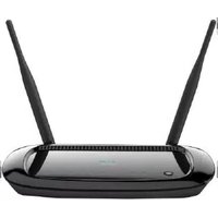
ESR600H - Router ENGENIUS - Free user manual and instructions
Find the device manual for free ESR600H ENGENIUS in PDF.


| Product Type | Wireless Router |
| Brand | EnGenius |
| Model | ESR600H |
| Wireless Standards | IEEE 802.11a/b/g/n (dual-band 2.4 GHz & 5 GHz) |
| Maximum Wireless Speed | 300 Mbps per band (600 Mbps total) |
| WAN Ports | 1 x 10/100/1000 Mbps Gigabit Ethernet |
| LAN Ports | 4 x 10/100/1000 Mbps Gigabit Ethernet |
| USB Ports | 1 x USB 2.0 |
| Antennas | 2 x external detachable dual-band antennas |
| Security | WPA/WPA2-PSK, WEP, WPS, SPI Firewall |
| Power Supply | DC 12V, 1A |
| Dimensions (W x D x H) | 185 x 130 x 30 mm |
| Weight | 0.3 kg |
| LED Indicators | Power, WAN, LAN (1-4), WLAN, WPS |
| Operation Temperature | 0°C to 40°C |
| Storage Temperature | -20°C to 70°C |
| Regulatory Certifications | FCC, CE |
| Mounting Options | Desktop, wall-mountable |
Frequently Asked Questions - ESR600H ENGENIUS
User questions about ESR600H ENGENIUS
0 question about this device. Answer the ones you know or ask your own.
Ask a new question about this device
Download the instructions for your Router in PDF format for free! Find your manual ESR600H - ENGENIUS and take your electronic device back in hand. On this page are published all the documents necessary for the use of your device. ESR600H by ENGENIUS.
USER MANUAL ESR600H ENGENIUS
natural_image
Front view of a wireless router with two antennas and a blue logo on the cover (no visible text or symbols)ESR600H/ESR750H
Dual Concurrent Wireless Media Router
V1.0
TABLE OF CONTENTS
Conventions 0-xi
Copyright 0-xiii
Product Overview
Product Overview....1-1
Features 1-1
Package Contents 1-3
Product Layout....1-4
Installation
System Requirements 2-1
Wall Mounting....2-2
EnGenius Quick Start
Installing the Software 3-1
Setup Notes 3-1
Installation....3-1
Connecting Network Cables....3-3
Web Configuration
Logging In. 4-1
Viewing the Dash Board....4-2
Services 4-3
Home 4-3
Setup Wizard 4-3
Network Settings 4-3
Language 4-3
Logout 4-3
Web Menus Overview 4-4
System 4-4
Internet 4-5
Wireless 2.4G 4-6
Wireless 5G....4-7
Firewall 4-8
Virtual Private Network 4-9
Advanced 4-10
Tools 4-11
Installation Setup Wizard
Detecting the Internet Connection 5-1
Basic Network Settings
System Setup....6-1
Viewing System Status 6-1
System 6-1
WAN Settings 6-2
LAN Settings....6-3
Wireless 2.4G Setting....6-3
Wireless 5G Setting 6-4
Configuring LAN 6-5
LAN IP 6-5
DHCP Server 6-6
DNS Server....6-7
Configuring DHCP 6-8
DHCP Client Table 6-8
Enable Static DHCP IP 6-8
Current Static DHCP Table....6-9
Configuring Logging....6-10
Log Message List 6-10
Monitoring Bandwidth Usage....6-11
Configuring Languages 6-12
Configuring WAN Settings 6-13
View WAN Status 6-13
WAN Settings 6-13
Configuring Dynamic IP....6-14
Dynamic IP 6-14
DNS Servers 6-15
Configuring Static IP 6-16
Static IP....6-16
Configuring PPPoE 6-17
Configuring PPTP 6-19
WAN Interface Settings....6-19
Dynamic IP Address....6-19
Static IP Address 6-20
PPTP Settings....6-21
Configuring L2TP....6-22
WAN Interface Settings....6-22
Dynamic IP Address....6-22
Static IP Address 6-23
L2TP Settings 6-24
Wireless 2.4G LAN Setup 6-25
Configuring Basic Settings....6-25
Access Point Mode....6-26
Wireless Distribution System Mode 6-27
Configuring Advanced Settings 6-30
Configuring Security 6-32
Encryption Type 6-33
Wired Equivalent Privacy (WEP) 6-33
Encryption: Wi-Fi Protected Access (WPA) Pre-Shared Key 6-34
Encryption: WPA RADIUS 6-35
Configuring Filter 6-36
Enable Wireless Access Control....6-36
MAC Address Filtering Table 6-37
Configuring Wi-Fi Protected Setup 6-38
Configuring Client List 6-39
Wireless LAN 5G Setup....6-40
Configuring Basic Settings....6-40
Access Point Mode. 6-41
Wireless Distribution System Mode 6-41
Configuring Advanced Settings 6-45
Configuring Security 6-47
Encryption Type 6-48
Wired Equivalent Privacy (WEP) 6-48
Encryption: Wi-Fi Protected Access (WPA) Pre-Shared Key 6-49
Encryption: WPA RADIUS 6-50
Configuring Filters 6-51
Enable Wireless Access Control....6-51
MAC Address Filtering Table 6-52
Configuring Wi-Fi Protected Setup 6-53
Configuring Client List 6-54
Firewall Setup....6-55
Configure Basic Settings 6-55
Configuring Advanced Settings 6-56
Configuring Demilitarized Zone 6-57
Configuring Denial of Service 6-58
WAN Settings 6-58
Virtual Private Network Setup 6-59
Viewing Status....6-59
Using the Virtual Private Network Wizard 6-60
L2TP 6-62
PPTP....6-64
Configuring a VPN Tunnel Profile 6-66
PPTP 6-67
L2TP 6-69
Configuring a User Profile 6-71
Creating a User Profile 6-71
Advanced Network Settings 6-72
NAT Setup....6-72
Port Mapping Setup....6-73
Port Forwarding Setup....6-75
Port Triggering Setup....6-77
Application Layer Gateway Setup 6-80
Universal Plug and Play Setup 6-81
Internet Group Multicast Protocol Setup 6-82
Quality of Service Setup 6-83
Priority Queue....6-84
Bandwidth Allocation....6-85
Routing Setup 6-86
NAT Disabled 6-86
NAT Enabled....6-87
Wake on LAN Setup 6-88
USB Port Setup 6-89
USB Access Mode 6-89
Tools Setup 6-91
Configuring the Administrator Account 6-91
Configuring the Router's Time....6-92
Configuring Dynamic Domain Name Service 6-93
Diagnosing a Network Connection 6-94
Upgrading Firmware 6-95
Backing Up Settings 6-96
Rebooting the Device 6-97
USB Services
USB Over IP 7-2
Using the USB Device Server 7-2
Introduction 7-2
Connect & Disconnect....7-2
Subnet Issue 7-2
Installation of a USB Device Driver....7-3
Using the USB Device Server....7-5
Printer and Scanner Sharing 7-6
Auto-Connected Printers....7-6
Viewing a List of Auto-Connected Printers....7-10
Removing a Printer from the Auto-Connect List....7-10
Printing to an Auto-Connected Printer 7-11
Configuring the Control Centre as a Windows Service 7-12
Network Scanners....7-14
Scanning with a USB Scanning Device and NetUSB....7-14
Storage 7-17
Request to Connect 7-18
Quitting the Control Center 7-19
Limitations....7-19
shAir Music 7-20
Using USB Speakers with shAir 7-20
Play Music from iTunes....7-22
Multiple Speakers 7-23
Streaming Music Stored from an iOS Device Directly to the shAir Music Server 7-24
Samba 7-26
Preliminary 7-26
Connecting USB Mass Storage to the Server....7-27
Supported Codepages 7-28
What is Codepage? 7-28
Filename Encoding of FAT File System....7-28
When do You Need to Configure Codepage? 7-28
Configuring the Server's Codepages 7-28
Using Shared Storage by USB Server Mode for Windows....7-29
Appendix A
Federal Communication Commission Interference Statement....A-1
Appendix B
Industry Canada Statement B-1
Appendix C
Link Layers....C-1
Dynamic IP Address (DHCP) C-1
Static IP....C-1
ESR600H/ESR750H USER GUIDE
TABLE OF CONTENTS
Point-to-Point Protocol over Ethernet (PPPoE). C-2
Layer 2 Tunneling Protocol (L2TP)....C-2
Appendix D
WorldWide Technical Support ....D-1
Conventions
The following conventions are used to give the user additional information about specific procedures or content. It is important to pay attention to these conventions as they provide information to prevent damage to equipment or personal injury.
General Conventions
The following general conventions are used in this document.

CAUTION!
CAUTIONS APPEAR BEFORE THE TEXT IT REFERENCES. CAUTIONS APPEAR IN CAPITAL LETTERS TO EMPHASIZE THAT THE MESSAGE CONTAINS VITAL HEALTH AND SAFETY INFORMATION.

WARNING!
Warning information appears before the text it references to emphasize that the content may prevent damage to the device or equipment.

Important:
Indicates information that is important to know for the proper completion of a procedure, choice of an option, or completing a task.

Note:
Indicates additional information that is relevant to the current process or procedure.

Example:
Indicates information used to demonstrate or explain an associated concept.
N/A:
Indicates that a component or a procedure is not applicable to this model.
Prerequisite:
Indicates a requirement that must be addressed before proceeding with the current function or procedure.
Typographical Conventions
The following typographical conventions are used in this document:
Italics
Indicates book titles, directory names, file names, path names, and program/process names.
Constant width
Indicates computer output shown on a computer screen, including menus, prompts, responses to input, and error messages.
Constant width bold
Indicates commands lines as entered on the computer. Variables contained within user input are shown in angle brackets (< >).
Bold
Indicates keyboard keys that are pressed by the user.
ESR600H/ESR750H USER GUIDE
COPYRIGHT
Copyright
This user guide and its content is copyright of © EnGenius Networks, 2011. All rights reserved.
Any redistribution or reproduction in part or in whole in any form is prohibited.
Do not distribute, transmit, store in any form of electronic retrieval system or commercially exploit the content without the expressed written permission of EnGenius Networks.
Product Overview
1.1 Product Overview
Thank you for purchasing the ESR600H/ESR750H Dual Concurrent Wireless Router from EnGenius Networks.
The EnGenius ESR600H/ESR750H Dual Concurrent Wireless Router is a member of the X-TRA RANGE series of routers.
The ESR600H/ESR750H offers 1 WAN and 4 LAN Gigabit connections and extended signal coverage with two external high gain 5dBi antennas. The ESR600H/ESR750H also features one USB port for SAMBA, NetUSB and shAir Music (ESR750H) functionality. The added features provide USB storage, printer and speaker sharing over a trusted network.
The ESR600H/ESR750H provides advanced security features to protect your network and the devices connected to it. An SPI Firewall protects the LAN as well as data sent over the Internet. For clients that want a direct, secure connection the router supports VPN lite tunneling. Data encryption protocols, such as WEP, WPA, WPA2 and TKIP/AES, IEEE802.1x Authentication and MAC Address Filtering are some of the other features which block access from unauthorized clients and better protect the network environment.
The ESR600H/ESR750H provides energy saving technology through the wireless LAN and supports Multiple SSID and Wi-Fi scheduling. It allows users to login to different SSIDs with different access rights. Wi-Fi Scheduling allows administrators to better manage Wi-Fi accessibility.
The ESR750H provides one USB2.0 port which supports SAMBA, NetUSB and shAir Music. shAir Music allows the ESR750 to handle the playback action on any iTunes device or allows an iPhone/iPad/iPod Touch* to stream audio to USB speakers connected to the router. This feature offers wireless audio streaming from anywhere the signal is accessible.
Features
• Extended Signal Coverage
• Dual-Band Concurrent Technology
• High Performance Gigabit Connection
PRODUCT OVERVIEW
PRODUCT OVERVIEW
• QoS Wireless Multimedia
• Wireless LAN Power Saving
• Support IEEE802.1x Authentication
• SAMBA and NetUSB
• shAir Music (ESR750H only)
1.2 Package Contents
| ITEM QUANTITY | |
| Dual Concurrent Wireless Router | 1 |
| 5dBi Antennas | 2 |
| Quick Installation Guide | 1 |
| 12V/1.25A Power Adaptor | 1 |
| Ethernet Cable | 1 |
| User CD (with user manual) | 1 |
| Technical Support Card | 1 |
1.3 Product Layout
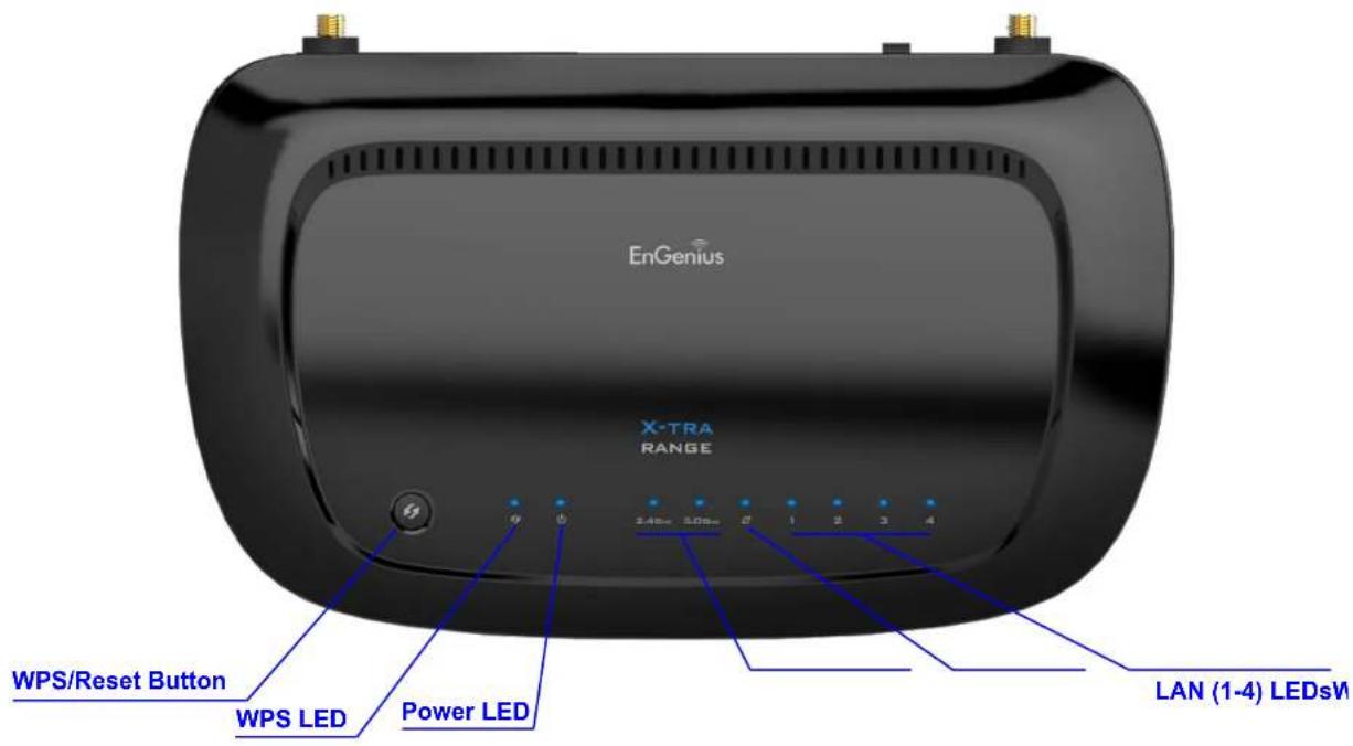
| FRONT PANEL COMPONENTS | DESCRIPTION |
| WPS/Reset Button | Wi-Fi Protected Setup button.To activate 2.4G WPS, press button for 0~5 seconds.To activate 5G WPS, press button for 5~10 seconds.N/A 10~15 secondsTo reset to factory settings, press button for > 15 seconds. |
| Power LED | Power status LED. |
| WLAN LED | Wireless LAN (WLAN) status LED. |
| WAN LED | Network status LED. |
| LAN (1 – 4) LEDs | LAN port status LED(s). |

| BACK PANEL COMPONENTS | DESCRIPTION |
| External Antenna Connectors | External interface for the antennas. |
| Power Switch | Turns the router on or off. |
| DC Power Slot | Connects the router to a DC power adapter source. |
| LAN Ports (1 – 4) | Connects up to four computers (4) to a local area network (LAN) using Ethernet cable. |
| WAN Port | Connects the router to a cable or DSL modem using an Ethernet cable. |
| USB Port | Provides Samba, NetUSB and shAir connectivity to devices on the LAN. |
Installation
2.1 System Requirements
To install the ESR600H/ESR750H, you need the following:
• Computer (Windows, Linux and MAC OS X Operating Systems)
- CD-ROM*
• Web Browser (Internet Explorer, FireFox, Chrome, Safari)
• Network Interface Card with an open RJ-45 Ethernet Port
• Wi-Fi Card or USB Wi-Fi Dongle (802.11 B/G/N)**
- External xDSL (ADSL) or Cable Modem with an open RJ-45 Ethernet Port
• RJ45 Ethernet Cables

Note:
*Using ESR600H/ESR750H Setup CD
**Optional
2.2 Wall Mounting
Mounting the ESR600H/ESR750H on a wall optimizes the wireless access range.

Note:
Choose a location that is within reach of an electrical outlet for the AC adapter and the DSL or Cable modem.
To mount the device on the wall do the following:
- Measure the distance from the middle of each mounting screw hole.
- Mark the locations of the screw holes on the wall.
- Drill a hole for each marked location and insert a screw in each.

Note:
Make sure to leave enough of the screw head above the wall surface to secure the router.
- Install and secure the mounts onto the ESR600H/ESR750H.
- Install the ESR600H/ESR750H on the wall.
EnGenius Quick Start
3.1 Installing the Software

Note:
Before getting started, please power off the cable or DSL modem.
Setup Notes
When considering the placement of the ESR600H/ESR750H remember the following:
- It must be located close to a DSL or Cable modem.
- It must be close to an electrical outlet.
- Upon first setup, it must be close to the computer that is used to set up and configure the router.
- For optimal wireless access place the router in the center of the room, at a high altitude and with an unobstructed view of the other wireless devices.
- Other electronic devices can interfere with the wireless frequency of the router and reduce the wireless access range.
Installation

Note:
If the instructions do not automatically start, open a file manager and browse the root folder of the CD-ROM. Look for the file named index.html and open it.
- Insert the ESR600H/ESR750H installation CD into the CD-ROM drive.

natural_image
Line drawing of a hand pressing a circular component into a rectangular block (no text or symbols)- Click Quick Start. The wizard will guide you through setting up your ESR600H/ESR750H.

3.2 Connecting Network Cables

CAUTION!
Unplug all peripherals and the router's adapter before starting with this procedure.
- Connect the adapter cable to an electrical outlet.
Note:
The Power LED lights up to show the device is active.
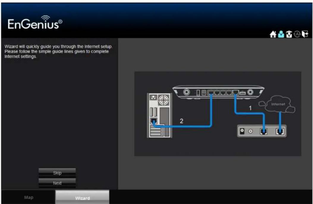
- Plug one end of the Ethernet cable (1) into the WAN port on the back panel of the router. Plug the other end of the cable into the cable or DSL modem.

- Plug one end of an Ethernet cable (2) into the LAN port on the back panel of the router. Plug the other end of the cable into the Ethernet port of the computer.
- Click Next to display the login screen.

flowchart
graph TD
    A["Server"] -->|2| B["Interface 1"]
    B --> C["Interface 2"]
    C --> D["Cloud"]
    style A fill:#f9f,stroke:#333
    style B fill:#bbf,stroke:#333
    style C fill:#dfd,stroke:#333
    style D fill:#dfd,stroke:#333

Note:
If the browser does not show the login screen, enter the default router IP address, 192.168.0.1.

Note:
Make sure the network cable and power adapter are firmly connected.
Web Configuration
4.1 Logging In

Note:
If the login screen does not display, enter the default router IP address of 192.168.0.1.
Note:
The default user name is admin and the default password is admin.
- At the login screen enter a user name and a password.
- Click Login to continue.

4.2 Viewing the Dash Board
The main screen, or dashboard, provides access to all of the router's services.

Services
The Home, Setup Wizard, Network Settings and Exit links are the main service areas.
Home
The Home link displays the dashboard screen.
Setup Wizard
The Setup Wizard link starts the wizard that automatically configures the router. Refer to "Detecting the Internet Connection" on page 5-1.
Network Settings
The Network Settings link displays the menus to manually configure the router. Refer to "Web Menus Overview" on page 4-4.
Language
The Language link displays the menu to set the OSD language. Refer to "Configuring Languages" on page 6-12.
Logout
The Logout link closes the router configuration software.
4.3 Web Menus Overview
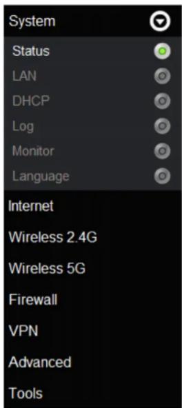
System
View and edit settings that affect system functionality.
- Status Display the summary of the current system status.
• LAN Configure the wired network.
• DHCP Configure dynamically allocated IP addresses. - Log View recorded system operations and network activity events.
• Monitor View the current network traffic bandwidth usage. - Language Configure the application menu and GUI language.
Internet
View and edit settings that affect network connectivity.
- Status Display the summary of the Internet status and type of connection.
• Dynamic IP Setup a dynamic IP connection to an Internet service provider (ISP).
• Static IP Setup a static IP connection to an ISP. - PPPoE Setup a PPPoE connection to an ISP.
- PPTP Setup a PPTP connection to an ISP.
• L2TP Setup an L2TP connection to an ISP.

Wireless 2.4G
View and edit settings for 2.4G wireless network connectivity.
- Basic Configure the minimum settings required to setup a wireless network connection.
- Advanced Configure the advanced network settings.
• Security Configure the wireless network security settings. - Filter Configure a list of clients that are allowed to wirelessly connect to the network.
- WPS Automate the connection between the a wireless device and the router using an 8-digit PIN.
- Client List View the 2.4G wireless devices currently connected to the network.

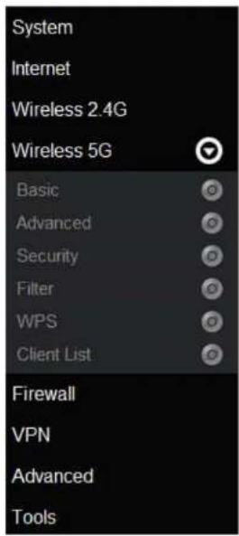
Wireless 5G
View and edit settings for 5G wireless network connectivity.
- Basic Configure the minimum settings required to setup a wireless network connection.
- Advanced Configure the advanced network settings.
• Security Configure the wireless network security settings. - Filter Configure a list of clients that are allowed to wirelessly connect to the network.
- WPS Automate the connection between the a wireless device and the router using an 8-digit PIN.
- Client List View the 5G wireless devices currently connected to the network.
Firewall
View and configure settings for firewall rule sets.
- Basic Enable or disable the network firewall.
- Advanced Configure virtual private network (VPN) packets.
- DMZ Redirect packets from the WAN port IP address to a particular IP address on the LAN.
- DoS Enable or disable blocking of denial of service (DoS) attacks.

Virtual Private Network
View and configure settings for VPN tunnelling.
• Status View the status of current VPN tunnels.
• Profile Setting Manually configure VPN tunnels.
- User Setting Configure users, user ID and password combinations, and assign access to specific VPN tunnels.
- Wizard Automatically configure VPN tunnels with guidance from the software.

Advanced
View and configure advanced system and network settings.
- NAT Enable or disable Network Address Translation (NAT).
- Port Mapping Re-direct a range of service port numbers to a specified LAN IP address.
- Port Forwarding Configure server applications to send and receive data from specific ports on the network.
- Port Triggering Configure applications that require multiple connections and different inbound and outbound connections.
• ALG Configure the application layer gateway (ALG). - UPnP Enable or disable Universal Plug and Play (UPnP) functionality.
- IGMP Enable or disable the Internet Group Multicast Protocol (IGMP).
- QoS Configure the network quality of service (QoS) setting by prioritizing the uplink and downlink bandwidth.
- Routing Configure static routing.
- WOL Configure wake on LAN (WOL) to turn on a computer over the network.
- USB port Configure the router's USB port to server or NetUSB mode.

Tools
View and configure system and network tools settings.
- Admin Configure the administrator password used to login to the router.
• Time Configure the system time on the router. - DDNS Map a static domain name to a dynamic IP address.
- Diagnosis Check if a specific computer is connected to the LAN.
- Firmware Update the router's firmware.
- Backup Load or save configuration settings from a backup file or restore the factory default settings.
- Reset Manually reset the router.

Installation Setup Wizard
5.1 Detecting the Internet Connection
Use the Wizard to automatically detect the type of Internet connection.
- Insert the ESR600H/ESR750H Installation CD into your CD-ROM drive to display the EnGenius Smart Wizard screen.

- Click Quick Start to continue an display the Wizard Introduction screen.
-
Click Next to continue or Skip to cancel the wizard.
-
The Wizard displays a progress bar while detecting the type of Internet connection.


Note:
This process may take several seconds.
- If the ESR600H/ESR750H can not detect the type of Internet connection, the following screen is displayed.

- Select a login method from the dropdown list.
- Fill in the required information.

Note:
There are four methods available to connect to the Internet: DHCP, Static IP, PPPoE and LT2P. For a description of each method, refer to "Link Layers" on page C-1. For configuration instructions, refer to "Configuring Dynamic IP" on page 6-14, "Configuring Static IP" on page 6-16, "Configuring PPPoE" on page 6-17 and "Configuring L2TP" on page 6-22.
-
Click Next to save these settings and continue to the next step; click Rescan to detect the Internet connection method; click Skip to discard changes and continue to the next step.
-
For the Wireless 2.4G connection, in the SSID text field enter a router name and in the Key text field enter a password.

WARNING!
Select High as the security level to best secure the wireless network.

- For the Wireless 5G connection, in the SSID text field enter a router name and in the Key text field enter a password.

WARNING!
Select High as the security level to best secure the wireless network.
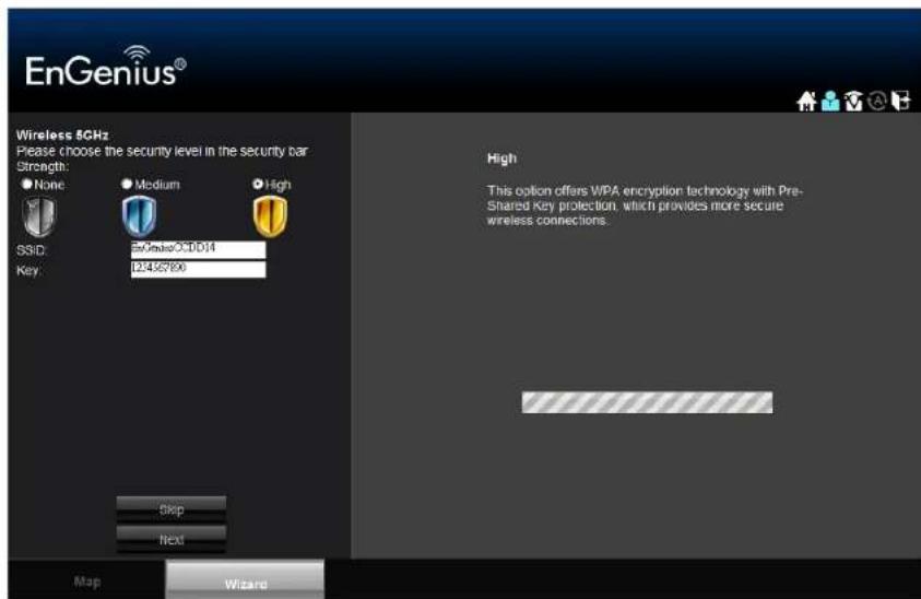
-
Click Next to save these settings or click Skip to discard changes and continue to the next step.
-
Review the settings.

- Click Apply to save the information entered in the previous steps. The ESR600H/ESR750H setup is complete.
Basic Network Settings
6.1 System Setup
6.1.1 Viewing System Status
The status page shows the summary of the current system status including system (hardware/software version, date/time), Internet connection (WAN), wired network (LAN) and wireless network (WLAN) information.
System
- Model The model name of the ESR600H/ESR750H.
- Mode The router's operating mode (AP / Router / WDS).
- Uptime The amount of time the device has been active.
- Current Date/Time The current system date and time.
- Hardware Version The hardware version number of the ESR600H/ESR750H.
- Serial Number The serial number of the ESR600H/ESR750H. The serial number is required for customer service or support.
- Application Version The firmware version number of the ESR600H/ESR750H.
Note:
To update the firmware visit www.engeniusnetworks.com.
| System | |
| Model | Wireless Gigabit Dualband Router |
| Mode | AP Router |
| Uptime | 17 min 22 sec |
| Current Date/Time | 2011/01/01 00:18:19 |
| Hardware Version | 1.0.0 |
| Serial Number | 000000001 |
| Application Version | 1.0.0 |
WAN Settings
- Attain IP Protocol Displays the IP protocol in use for the ESR600H/ESR750H. It can be a dynamic or static IP address.
- IP Address The router's IP address as designated by an ISP provider.
- Subnet Mask The router's WAN subnet mask as designated by an ISP provider.
- Default Gateway The router's gateway address as designated by an ISP provider.
- MAC Address The router's WAN MAC address. The router's MAC address is located on the label on the back side of the router.
• Primary DNS The primary DNS of an ISP provider.
• Secondary DNS The secondary DNS of an ISP provider.
WAN Settings
| Attain IP Protocol | Dynamic IP Address |
| IP Address | --- |
| Subnet Mask | --- |
| Default Gateway | --- |
| MAC Address | 00:AA:BB:CC:DD:11 |
| Primary DNS | --- |
| Secondary DNS | --- |
LAN Settings
- IP Address The router's local IP address. The default LAN IP address is 192.168.0.1.
- Subnet Mask The router's local subnet mask.
- DHCP Server: The DHCP setting status (Default: Enabled).
• MAC Address The router's LAN MAC address.
| LAN Settings | |
| IP Address | 192.168.1.220 |
| Subnet Mask | 255.255.255.0 |
| DHCP Server | Enabled |
| MAC Address | 00:00:00:9A:C0:64 |
Wireless 2.4G Setting
- Channel The communications channel used by all stations, or computing devices, on the network.
- ESSID The ID value of a set of one or more interconnected basic service sets (BSSs).
• Security The security setting status (Default: Disabled). - BSSID The unique ID of the BSS using the above channel value on this router. The ID is the MAC address of the BSSs access point.
• Associated Clients The number of clients associated with this SSID.
| WLAN Settings | |
| Wireless 2.4G Setting | |
| Channel | 11 |
| SSID_1 | |
| ESSID | EnGeniusCCDD10 |
| Security | Disable |
| BSSID | 00:00:00:9A:C0:64 |
| Associated Clients | 0 |
Wireless 5G Setting
- Channel The communications channel used by all stations, or computing devices, on the network.
- ESSID The ID value of a set of one or more interconnected basic service sets (BSSs).
• Security The security setting status (Default: Disabled). - BSSID The unique ID of the BSS using the above channel value on this router. The ID is the MAC address of the BSSs access point.
- Associated Clients The number of clients associated with this SSID.

6.1.2 Configuring LAN
Configure the wired network settings in the LAN section. The router's IP is defined in the IP Address field. The default setting of the DHCP server is set to enabled so that network clients can be automatically assigned a virtual IP addresses. Advanced users may configure DNS server settings to meet specific requirements. Changing the settings in this section are not necessary for most situations.

Note:
Keep the default values if you are uncertain of the settings values.
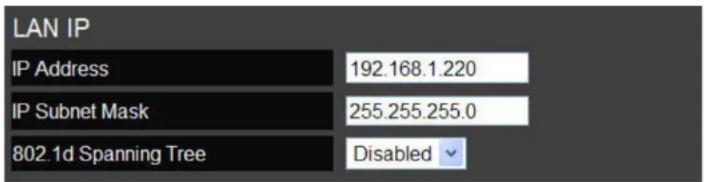
LAN IP
IP Address Configure the router's LAN IP address.
IP Subnet Mask Configure the router's LAN Subnet Mask
802.1d Spanning Tree The 802.1d Spanning Tree settings is disabled by default. When enabled, the spanning tree protocol is applied to prevent network loops (transmissions won't pass the same node twice to reach the destination).
DHCP Server
The DHCP server assigns IP addresses to the devices on the LAN.
DHCP Server Enable or disable the DHCP server (Default: Enabled).
Lease Time Configure the amount of time each allocated IP address can be used by a client.
Start IP The first IP address in the range of addresses assigned by the router.
End IP The last IP address in the range of addresses assigned by the router.
Domain Name: The domain name of the router.

DNS Server
The domain name system (DNS) server translates a domain or website name into a uniform resource locator (URL), or Internet address. There are four options to choose from: From ISP, User-Defined, DNS Relay or None. Select From ISP to retrieve the DNS address value from the ISP; select User-Defined to assign a custom DNS server address; select DNS Relay to forward all queries to a relay, which in turn sends them to an ISP's DNS server; select None to assign no server.
First DNS Server Configure the first, or primary, DNS server. (Default = DNS Relay)
Second DNS Server Configure the second, or secondary, DNS server. (Default = None)

Click Apply to save the settings.

6.1.3 Configuring DHCP
View active dynamically allocated IP (DHCP) addresses and configure and view static DHCP IP addresses.

WARNING!
Do not modify the settings in this section without a thorough understanding of the parameters.
DHCP Client Table
Displays the connected DHCP clients whose IP addresses are assigned by the DHCP server on the LAN.
Click Refresh to update the table.

Enable Static DHCP IP
Click Enable Static DHCP IP to add more static DHCP IP addresses.
Click Reset to return the table to its previous state.

Current Static DHCP Table
Active static DHCP addresses are listed along with the associated MAC addresses.
Click Delete Selected to remove a selected address.
Click Delete All to remove all addresses from the table.
Click Reset to return the table to its previous state.
Click Apply to save the settings.


6.1.4 Configuring Logging
The logging service records and displays important system information and activity on the network. The events are stored in a memory buffer with older data overwritten by newer when the buffer is full.
Log Message List
Shows the current system operations and network activity.
![day 1 00:00:12 [SYSTEM]: WAN, No PHY Link day 1 00:00:09 [SYSTEM]: WAN, start DHCP mode day 1 00:00:06 [SYSTEM]: WAN, stop DHCP mode day 1 00:00:05 [SYSTEM]: ECODES, start NuUSB day 1 00:00:05 [SYSTEM]: WLAN, start LLTO day 1 00:00:04 [SYSTEM]: HTTP, start day 1 00:00:04 [SYSTEM]: NET, start Firewall day 1 00:00:04 [SYSTEM]: NET, start NAP day 1 00:00:04 [SYSTEM]: NTP, start NTP Client day 1 00:00:03 [SYSTEM]: DHCP, DHCP Server Stoping day 1 00:00:03 [SYSTEM]: DNS, start DNS Proxy day 1 00:00:03 [SYSTEM]: WAN, No PHY Link day 1 00:00:03 [SYSTEM]: WAN, start DHCP mode day 1 00:00:02 [SYSTEM]: WLAN[2.4G], Channel = 11 day 1 00:00:02 [SYSTEM]: WLAN[2.4G], CountryRegion = 0](/content/2026/06/1254915/images/4805cec0b3598730e67a33706107c848a5a6270f6143cf067b6e38a72146d998.jpg)
Click Save to store data to a log file.
Click Clear to empty the log file.
Click Refresh to empty the log file and begin updating it with new data.

6.1.5 Monitoring Bandwidth Usage
View bandwidth usage for LAN and WLAN traffic.
Displays the bandwidth usage for the WLAN and LAN networks.

bar
| Bandwidth Monitor | TX | Rx | | --- | --- | --- | | WAN | 0.1 | 0.2 | | 2.4G WLAN | 0.3 | 0.7 | | 5G WLAN | 0.9 | 0.1 |6.1.6 Configuring Languages
The router supports multiple languages for using the graphical user interface (GUI).
Select the language to use from the dropdown list.

6.2 Configuring WAN Settings
6.2.1 View WAN Status
The WAN Settings, or Internet Status, page shows a summary of the current Internet connection information. This section is also shown on the System Status page.
WAN Settings
- Attain IP Protocol Display the IP Protocol type used for the ESR600H/ESR750H (Dynamic IP Address or Static IP Address).
- IP Address The router's WAN IP address.
- Subnet Mask The router's WAN subnet mask.
- Default Gateway The ISP's gateway IP address.
- MAC Address The router's WAN MAC address. The router's MAC address is located on the label on the back side of the router.
- Primary DNS The primary DNS address of an ISP provider.
- Secondary DNS: The secondary DNS address of an ISP provider.
WAN Settings
| Attain IP Protocol | Dynamic IP Address |
| IP Address | --- |
| Subnet Mask | --- |
| Default Gateway | --- |
| MAC Address | 00:AA:BB:CC:DD:11 |
| Primary DNS | --- |
| Secondary DNS | --- |
6.2.2 Configuring Dynamic IP
Dynamic IP addressing assigns a different IP address each time a device connects to an ISP service provider. The service is most commonly used by ISP cable providers.
Dynamic IP
- Host name Assign a name for the internet connection type. This field can be blank.
- MTU Configure the maximum transmission unit (MTU). The MTU specifies the largest packet size permitted for an internet transmission. The factory default MTU size for Dynamic IP (DHCP) is 1500. The MTU size can be set between 512 and 1500.
- Clone MAC Enter the MAC address of the devices' network interface card (NIC) in the MAC address field and click Clone MAC.
Note:
Some ISP providers require registering the MAC address of the network interface card (NIC) connected directly to the cable or DSL modem. Clone MAC masks the router's MAC address with the MAC address of the device's NIC.

DNS Servers
The DNS server translates a domain or website name into a uniform resource locator (URL), or Internet address. There are two options to choose from: From ISP or User-Defined. Select From ISP to retrieve the DNS address value from the ISP; select User-Defined to assign a custom DNS server address.
- DNS Server Configure the type of DNS server. (Default = From ISP)
- First DNS Server Configure the first, or primary, DNS server.
- Second DNS Server: Configure the second, or secondary, DNS server.
Click Apply to save the settings.

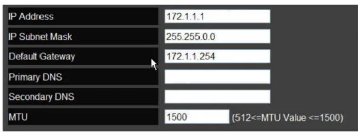
6.2.3 Configuring Static IP
Setting a static IP address allows an administrator to set a specific IP address for the router and guarantees that it can not be assigned a different address.
Static IP
- IP Address The router's WAN IP address.
- Subnet Mask The router's WAN subnet mask.
- Default Gateway The router's gateway address.
• Primary DNS The primary DNS server address.
• Secondary DNS The secondary DNS server address. - MTU The maximum transmission unit (MTU) specifies the largest packet size permitted for an internet transmission. The factory default MTU size for static IP is 1500. The MTU size can be set between 512 and 1500.
Click Apply to save the settings.
6.2.4 Configuring PPPoE
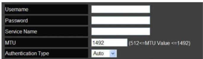
Point-to-Point Protocol over Ethernet (PPPoE) is used mainly by ISPs that provide DSL modems to connect to the Internet.
- Login Enter the username assigned by an ISP.
- Password Enter the password assigned by an ISP.
- Service Name Enter the service name of an ISP (optional).
- MTU Enter the maximum transmission unit (MTU). The MTU specifies the largest packet size permitted for an internet transmission (PPPoE default: 1492). The MTU size can be set between 512 and 1492.
- Authentication Type Select the type of authentication provided by the ISP: Auto, PAP, or CHAP. If unsure of the best setting, select Auto.
- Type Configure the connection type between the router and the ISP. Choose between Keep Connection, Automatic Connection or Manual Connection.
- Idle Timeout Configure the maximum idle time (1 to 1,000 minutes) allowed for an inactive connection.
- Clone MAC Enter the MAC address of the devices' network interface card (NIC) in the MAC address field and click Clone MAC.
Note:
Some ISP providers require registering the MAC address of the network interface card (NIC) connected directly to the cable or DSL modem. Clone MAC masks the router's MAC address with the MAC address of the device's NIC.
Click Apply to save the settings or Cancel to discard the changes.

6.2.5 Configuring PPTP
The point-to-point tunnelling protocol (PPTP) is used in association with virtual private networks (VPNs). There a two parts to a PPTP connection: the WAN interface settings and the PPTP settings.
WAN Interface Settings
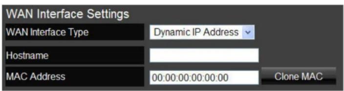
Dynamic IP Address
- WAN Interface Type Select Dynamic IP Address to assign an IP address provided by an ISP.
- Hostname Enter a host name of an ISP. (optional).
- Clone MAC Enter the MAC address of the devices' network interface card (NIC) in the MAC address field and click Clone MAC.
Note:
Some ISP providers require registering the MAC address of the network interface card (NIC) connected directly to the cable or DSL modem. Clone MAC masks the router's MAC address with the MAC address of the device's NIC.
Static IP Address
- WAN Interface Type Select Static IP Address to assign a specific IP address for the router.
- My IP Address Enter the custom IP address.
• My Subnet Mask Enter the custom subnet mask. - Gateway IP Address Enter the custom gateway IP address.

PPTP Settings
- User Name Enter the username assigned by your ISP.
- Password: Enter the password assigned by your ISP.
- Service IP Address: Enter the PPTP server IP address provided by your ISP.
- Connection ID: Enter the connection ID provided by your ISP (optional).
- MTU Enter the maximum transmission unit (MTU). The MTU specifies the largest packet size (Default: 1462) permitted for an internet transmission. The MTU size can be set between 512 and 1492.
- Type Configure the connection type between the router and the ISP. Choose between Keep Connection, Automatic Connection or Manual Connection.
- Idle Timeout Configure the maximum amount of time, in minutes, allowed for inactive Internet connection. The Internet connection will be dropped when the maximum idle time is reached. Valid values are between one and one thousand.
Click Apply to save the settings or Cancel to discard the changes.


6.2.6 Configuring L2TP
The layer 2 tunneling protocol (L2TP) is used in association with virtual private networks (VPNs). There a two parts to a L2TP connection: the WAN interface settings and the L2TP settings.
WAN Interface Settings
Dynamic IP Address
- WAN Interface Type Select Dynamic IP Address to assign an IP address provided by an ISP.
- Hostname Enter a host name of an ISP (optional).
- Clone MAC Enter the MAC address of the devices' network interface card (NIC) in the MAC address field and click Clone MAC.

Note:
Some ISP providers require registering the MAC address of the network interface card (NIC) connected directly to the cable or DSL modem. Clone MAC masks the router's MAC address with the MAC address of the device's NIC.
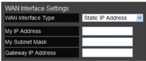
Static IP Address
- WAN Interface Type Select Static IP Address to assign a specific IP address for the router.
- My IP Address Enter the custom IP address.
• My Subnet Mask Enter the custom subnet mask. - Gateway IP Address Enter the custom gateway IP address.
L2TP Settings
- User Name Enter the username assigned by an ISP.
- Password: Enter the password assigned by an ISP.
- Service IP Address: Enter the L2TP server IP address provided by an ISP.
- Connection ID: Enter the connection ID provided by an ISP (optional).
- MTU Enter the maximum transmission unit (MTU). The MTU specifies the largest packet size (Default: 1460) permitted for an internet transmission. The MTU size can be set between 512 and 1492.
- Type Configure the connection type between the router and the ISP. Choose between Keep Connection, Automatic Connection or Manual Connection.
- Idle Timeout Configure the maximum amount of time, in minutes, allowed for inactive Internet connection. The Internet connection will be dropped when the maximum idle time is reached. Valid values are between one and one thousand.
Click Apply to save the settings or Cancel to discard the changes.


6.3 Wireless 2.4G LAN Setup
6.3.1 Configuring Basic Settings
- Radio Enable or disable the wireless radio. If the wireless radio is disabled, wireless access points are not available.
- Mode Select the wireless operating mode for the router. Two modes are available: Access Point or Wireless Distribution System (WDS) mode.
- AP Provides a connection access point for wireless devices.
- WDS Allows the wireless network to be expanded using multiple access points without wired connections.

Access Point Mode
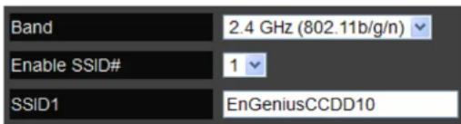
Configure the wireless settings of the router in access point mode.
- Band: Select a wireless standard for the network from the following options:
• 2.4 GHz (B)
• 2.4 GHz (G)
• 2.4 GHz (N)
• 2.4 GHz (B+G)
• 2.4 GHz (B+G+N)
- Enable SSID# Select the number of wireless groups, between one and four, available on the network.
- SSID[#] Enter the name of the wireless network(s).
-
Auto Channel Enable or disable having the router automatically select a channel for the wireless network. Auto channel is enabled by default. Select disable to manually assign a specific channel. (Default = Disable)
-
Check Channel Time When auto channel is enabled, select time period that the system checks the appropriate channel for the router.
- Channel When auto channel is disabled, select a channel to assign to the wireless network. Valid value are from one to eleven in the US and one to thirteen in the EU.


Wireless Distribution System Mode
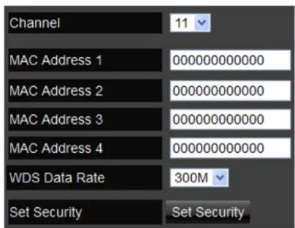
Configure the router's wireless settings in WDS mode.
- Channel Select a channel to assign to the wireless network. Valid value are from one to eleven in the US and one to thirteen in the EU.
- MAC Address [#] Enter the MAC address(es) for the wireless access point(s) that are part of the WDS.
• WDS Data Rate Select the data rate for the WDS. - Set Security Click Set Security to display the WDS security settings screen. For security configuration settings, refer to "WDS Security Settings Screen" on page 6-28.
Click Apply to save the settings or Cancel to discard changes.
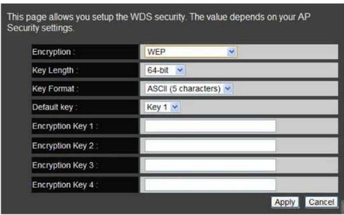
WDS Security Settings Screen
Select the type of WDS encryption (Disable, WEP or WPA Pre-Shared Key) for the wireless network.
Wired Equivalent Privacy (WEP)
• Key Length Select between 64-bit and 128-encryption.
- Key Format Select the type of characters used for the WEP Key: ASCII (5 characters) or Hexadecimal (10 characters).
- Default Key Select the default encryption key for wireless transactions.
- Encryption Key [#] Enter the encryption key(s) used to encrypt the data packets during data transmission.
Click Apply to save the settings or Cancel to discard changes.
Wi-Fi Protected Access (WPA) Pre-Shared Key
• WPA Type Select the type of WPA.
- WPA Temporal Key Integrity Protocol (TKIP) Generates a 128-bit key for each packet.
- WPA2 Advanced Encryption Standard (AES) Government standard packet encryption which is stronger than TKIP.
- WPA2 Mixed Mixed mode allows device to try WPA2 first, and if that fails selects WPA type.
- Pre-Shared Key Type Select the type of pre-shared key as Passphrase (ASCII) or Hexadecimal.
• Pre-Shared Key Enter the pre-shared Key value.
Click Apply to save the settings or Cancel to discard changes.

6.3.2 Configuring Advanced Settings
Advanced settings parameters available on the router.

WARNING!
Incorrectly changing these settings may cause the device to stop functioning. Do not modify the settings in this section without a thorough understanding of the parameters.
- Fragment Threshold Enter the maximum size of a packet during data transmission. A value too low could lead to low performance.
- RTS Threshold Enter the RTS threshold. If the packet size is smaller than the RTS threshold, the ESR600H/ESR750H does not use RTS/CTS to send the data packet.
- Beacon Interval Enter the beacon interval. This is the amount of time that the ESR600H/ESR750H sets to synchronize the network.
• Delivery Traffic Indication Message (DTIM) Period
Enter the DTIM period. The DTIM is a countdown period informing clients of the next point of broadcast and multicast of messages over the network. Valid values are between 1 and 255.

other
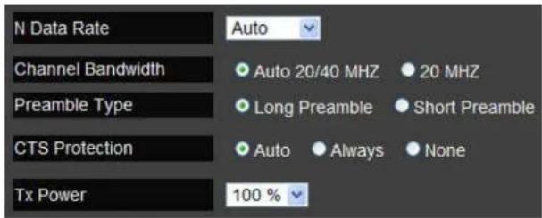
| Metric | Value | Timeframe | | :--- | :--- | :--- | | Fragment Threshold | 2346 | (256–2346) | | RTS Threshold | 2347 | (1–2347) | | Beacon Interval | 100 | (20–1024 ms) | | DTIM Period | 1 | (1–255) |- N Data Rate Select the N data rate. This is the rate in which the ESR600H/ESR750H will transmit data packets to wireless N compatible devices.
- Channel Bandwidth Select the channel bandwidth. The factory default is Auto 20/40MHz. The default setting provides the best performance by auto selecting channel bandwidth.
- Preamble Type Select the preamble type. Long Preamble provides better LAN compatibility and Short Preamble provides better wireless performance.
- CTS Protection Select the type of CTS protection. Using CTS Protection can lower the data collisions between Wireless B and Wireless G devices and lower data throughput.
- Tx Power Select the wireless signal strength level. Valid values are between 10% and 100%.
Click Apply to save the settings or Cancel to discard changes.

6.3.3 Configuring Security
Enable security options on the wireless network to prevent intrusions to systems on the wireless network.
- SSID Selection Select the wireless network group to change the wireless security settings for.
- Broadcast SSID Enable or disable broadcast SSID. Choose whether or not the wireless group is visible to other members.
- Wi-Fi Multimedia (WMM) Enable or disable quality of server (QoS) to optimize the streaming for bandwidth sensitive data such as HDTV video streaming, online gaming, VoIP, videoconferencing, and etc.
- Encryption Select the encrypt type for the router.
Click Apply to save the settings.


Encryption Type
Wired Equivalent Privacy (WEP)
- Authentication Type Select the type of authentication.
- Open System Wireless stations can associate with the ESR600H/ESR750H without WEP encryption
- Shared Key Devices must provide the corresponding WEP key(s) when connecting to the ESR600H/ESR750H.
- Auto
• Key Length Select between 64-bit and 128-encryption.
• Key Type Select the type of characters used for the WEP Key: ASCII (5 characters) or Hexadecimal (10 characters). - Encryption Key [#] Enter the encryption key(s) used to encrypt the data packets during data transmission.
Click Apply to save the settings.


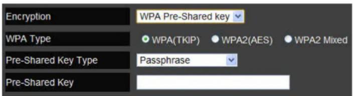
Encryption: Wi-Fi Protected Access (WPA) Pre-Shared Key
• WPA Type Select the type of WPA.
- WPA Temporal Key Integrity Protocol (TKIP) Generates a 128-bit key for each packet.
- WPA2 Advanced Encryption Standard (AES) Government standard packet encryption which is stronger than TKIP.
- WPA2 Mixed Mixed mode allows device to try WPA2 first, and if that fails selects WPA type.
- Pre-Shared Key Type Select the type of pre-shared key as Passphrase (ASCII) or Hexadecimal.
- Pre-Shared Key Enter the pre-shared Key value.
Click Apply to save the settings.

Encryption: WPA RADIUS
Use a RADIUS server to authenticate wireless stations and provide a session key to encrypt data during communications.
- WPA Type Select the type of Wireless Protected Access (WPA).
- WPA Temporal Key Integrity Protocol (TKIP) Generates a 128-bit key for each packet.
- WPA2 Advanced Encryption Standard (AES) Protects unauthorized access by verifying network users (encryption is stronger than TKIP).
- WPA2 Mixed Mixed mode allows device to try WPA2 first, and if that fails selects WPA type.
- RADIUS Server IP Address: Enter the IP address of the server.
- RADIUS Server Port: Enter the port number of the server.
- RADIUS Server Password: Enter the password of the server.
Click Apply to save the settings or Cancel to discard changes.


6.3.4 Configuring Filter

WARNING!
Incorrectly changing these settings may cause the device to stop functioning. Do not modify the settings in this section without a thorough understanding of the parameters.
When Enable Wireless Access Control is selected, only wireless clients with MAC addresses listed in the table are allowed to connect to the wireless network.
Enable Wireless Access Control
- Description Enter a description of the device allowed to connect to the network.
- MAC Address Enter the MAC address of the wireless device.

Click Add to append a new device to the list or Reset to discard changes.
MAC Address Filtering Table
• No. The sequence number of the device.
• Description The description of the device.
• MAC Address The MAC address of the device.
- Select Indicates the device(s) that can have actions performed on them.
Click Delete Selected to remove selected devices from the list.
Click Delete All to remove all devices form the list. Click Reset the discard changes.
Click Apply to save the settings or Cancel to discard changes.


6.3.5 Configuring Wi-Fi Protected Setup
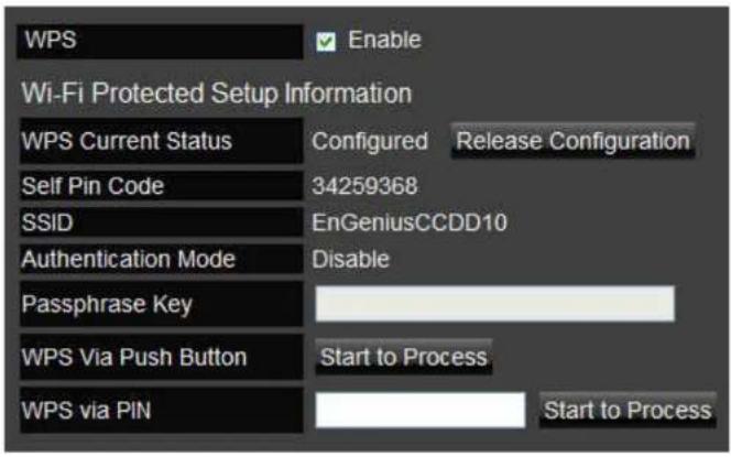
Wi-Fi protected setup (WPS) is an easy way to allow wireless clients to connect to the ESR600H/ESR750H. Automate the connection between the device and the ESR600H/ESR750H using a button or a PIN.
• WPS Enable or disable WPS.
- WPS Current Status A notification of whether or not wireless security is configured.
- Self Pin Code An 8-digit PIN which is required when configuring the router for the first time in Windows 7 or Vista.
• SSID The name of the wireless network.
- Authentication Mode The current security settings for the corresponding SSID.
• Passphrase Key A randomly generated key created by the ESR600H/ESR750H during WPS.
- WPS via Push Button Click Start to Process to activate WPS.
- WPS via PIN Enter the PIN of a wireless device click Start to Process to activate WPS.
6.3.6 Configuring Client List
View the 2.4G wireless devices currently connected to the ESR600H/ESR750H.
- Interface The type of network connected to the device.
- MAC Address The MAC address of device connected to network.
- Signal The signal strength of the device connected to the network.
- Idle Time The amount of time the connected device has not been active on the network.
Click Refresh to refill the list with currently connected devices.

6.4 Wireless LAN 5G Setup
6.4.1 Configuring Basic Settings
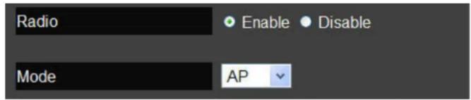
- Radio Enable or disable the wireless radio. If the wireless radio is disabled, wireless access points are not available.
- Mode Select the wireless operating mode for the router. Two modes are available: Access Point or Wireless Distribution System (WDS) mode.
- AP Provides an access point for wireless devices to connect to.
- WDS Access points expand the wireless coverage area by connecting to each other and acting as one.
Access Point Mode
Configure the wireless settings of the router in access point mode.
- Band: Select a wireless standard for the network from the following options:
- 5 GHz (802.11 a)
- 5 GHz (802.11 n)
-
5 GHz (802.11 a/n)
-
Enable SSID# Select the number of wireless groups, between one and four, available on the network.
- SSID[#] Enter the name of the wireless network(s).
-
Auto Channel Enable or disable having the router automatically select a channel for the wireless network. Auto channel is enabled by default. Select disable to manually assign a specific channel. (Default = Disable)
-
Check Channel Time When auto channel is enabled, select time period that the system checks the appropriate channel for the router.
- Channel When auto channel is disabled, select a channel to assign to the wireless network.
Wireless Distribution System Mode
Configure the wireless settings of the router in WDS mode.


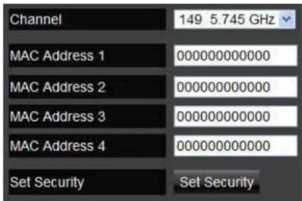
- Channel Select a channel to assign to the wireless network.
- MAC Address [#] Enter the MAC address(es) for the wireless access point(s) that are part of the WDS.
• WDS Data Rate Select the data rate for the WDS. - Set Security Click Set Security to display the WDS security settings screen. For security configuration settings, refer to "WDS Security Settings Screen" on page 6-43.
Click Apply to save the settings or Cancel to discard changes.

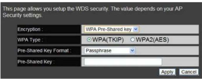
WDS Security Settings Screen
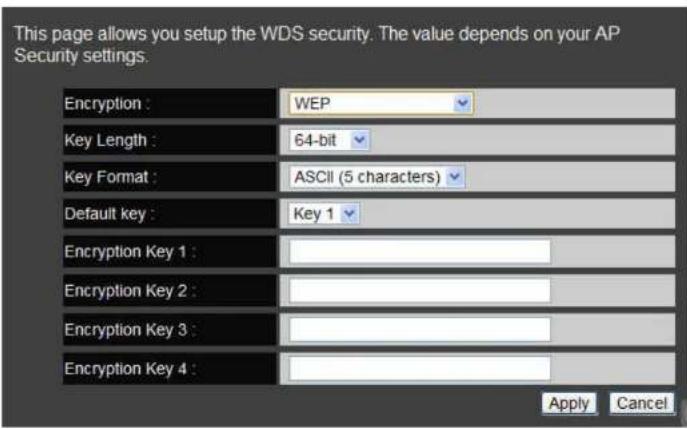
Select the type of WDS encryption (Disable, WEP or WPA Pre-Shared Key) for the wireless network.
Wired Equivalent Privacy (WEP)
• Key Length Select between 64-bit and 128-encryption.
- Key Format Select the type of characters used for the WEP Key: ASCII (5 characters) or Hexadecimal (10 characters).
- Default Key Select the default encryption key for wireless transactions.
- Encryption Key [#] Enter the encryption key(s) used to encrypt the data packets during data transmission.
Click Apply to save the settings or Cancel to discard changes.
Wi-Fi Protected Access (WPA) Pre-Shared Key
• WPA Type Select the type of WPA.
- WPA Temporal Key Integrity Protocol (TKIP) Generates a 128-bit key for each packet.
- WPA2 Advanced Encryption Standard (AES) Government standard packet encryption which is stronger than TKIP.
- WPA2 Mixed Mixed mode allows device to try WPA2 first, and if that fails selects WPA type.
- Pre-Shared Key Type Select the type of pre-shared key as Passphrase (ASCII) or Hexadecimal.
• Pre-Shared Key Enter the pre-shared Key value.
Click Apply to save the settings or Cancel to discard changes.
6.4.2 Configuring Advanced Settings
Advanced settings parameters available on the router.

WARNING!
Incorrectly changing these settings may cause the device to stop functioning. Do not modify the settings in this section without a thorough understanding of the parameters.
- Fragment Threshold Enter the maximum size of a packet during data transmission. A value too low could lead to low performance.
- RTS Threshold Enter the RTS threshold. If the packet size is smaller than the RTS threshold, the ESR600H/ESR750H will not use RTS/CTS to send the data packet.
- Beacon Interval Enter the beacon interval. This is the amount of time that the ESR600H/ESR750H will synchronize the network.
• Delivery Traffic Indication Message (DTIM) Period
Enter the DTIM period. The DTIM is a countdown period informing clients of the next point of broadcast and multicast of messages over the network. Valid values are between 1 and 255.

other
| Metric | Value | Timeframe | | :--- | :--- | :--- | | Fragment Threshold | 2346 | (256–2346) | | RTS Threshold | 2347 | (1–2347) | | Beacon Interval | 100 | (20–1024 ms) | | DTIM Period | 1 | (1–255) |- Data Rate: Select the data rate. This is the rate in which the ESR600H/ESR750H will transmit data packets to wireless devices.
- N Data Rate Select the N data rate. This is the rate in which the ESR600H/ESR750H will transmit data packets to wireless N compatible devices.
- Channel Bandwidth Select the channel bandwidth. The factory default is Auto 20/40MHz. The default setting provides the best performance by auto selecting channel bandwidth.
- Preamble Type Select the preamble type. Long Preamble provides better LAN compatibility and Short Preamble provides better wireless performance.
- Tx Power Select the wireless signal strength level. Valid values are between 10% and 100%.
- Country Selection Select the country where the wireless network is located.
Click Apply to save the settings or Cancel to discard changes.



6.4.3 Configuring Security
Enable security options on the wireless network to prevent intrusions to systems on the wireless network.
- SSID Selection Select the wireless network group to change the wireless security settings for.
- Broadcast SSID Enable or disable broadcast SSID. Choose whether or not the wireless group is visible to other members.
- Wi-Fi Multimedia (WMM) Enable or disable quality of server (QoS) to optimize the streaming for bandwidth sensitive data such as HDTV video streaming, online gaming, VoIP, videoconferencing, and etc.
- Encryption Select the encrypt type for the router.
Click Apply to save the settings.


Encryption Type
Wired Equivalent Privacy (WEP)
- Authentication Type Select the type of authentication.
- Open System Wireless stations can associate with the ESR600H/ESR750H without WEP encryption
- Shared Key Devices must provide the corresponding WEP key [up to 4] when connecting to the ESR600H/ESR750H.
- Auto The ESR600H/ESR750H automatically generates a passphrase.
• Key Length Select between 64-bit and 128-encryption.
• Key Type Select the type of characters used for the WEP Key: ASCII (5 characters) or Hexadecimal (10 characters). - Encryption Key [#] Enter the encryption key(s) used to encrypt the data packets during data transmission.
Click Apply to save the settings.
Note:
Do not use WEP type unless your device can not be upgraded to support WPA. Newer encryption types use stronger encryption than WEP.


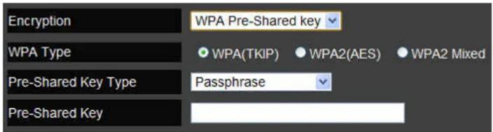
Encryption: Wi-Fi Protected Access (WPA) Pre-Shared Key
• WPA Type Select the type of WPA.
- WPA Temporal Key Integrity Protocol (TKIP) Generates a 128-bit key for each packet.
- WPA2 Advanced Encryption Standard (AES) Government standard packet encryption which is stronger than TKIP.
- WPA2 Mixed Mixed mode allows device to try WPA2 first, and if that fails selects WPA type.
- Pre-Shared Key Type Select the type of pre-shared key as Passphrase (ASCII) or Hexadecimal.
- Pre-Shared Key Enter the pre-shared Key value.
Click Apply to save the settings.

Encryption: WPA RADIUS
Use a RADIUS server to authenticate wireless stations and provide a session key to encrypt data during communications.
- WPA Type Select the type of Wireless Protected Access (WPA).
- WPA Temporal Key Integrity Protocol (TKIP) Generates a 128-bit key for each packet.
- WPA2 Advanced Encryption Standard (AES) Protects unauthorized access by verifying network users (encryption is stronger than TKIP).
- WPA2 Mixed Mixed mode allows device to try WPA2 first, and if that fails selects WPA type.
- RADIUS Server IP Address: Enter the IP address of the server.
- RADIUS Server Port: Enter the port number of the server.
- RADIUS Server Password: Enter the password of the server.
Click Apply to save the settings or Cancel to discard changes.


6.4.4 Configuring Filters

WARNING!
Incorrectly changing these settings may cause the device to stop functioning. Do not modify the settings in this section without a thorough understanding of the parameters.
When Enable Wireless Access Control is selected, only wireless clients with MAC addresses listed in the table are allowed to connect to the wireless network.
Enable Wireless Access Control
- Description Enter a description of the device allowed to connect to the network.
- MAC Address Enter the MAC address of the wireless device.

Click Add to append a new device to the list or Reset to discard changes.
MAC Address Filtering Table
• No. The sequence number of the device.
• Description The description of the device.
• MAC Address The MAC address of the device.
- Select Indicates the device(s) that can have actions performed on them.
Click Delete Selected to remove selected devices from the list.
Click Delete All to remove all devices form the list. Click Reset the discard changes.
Click Apply to save the settings or Cancel to discard changes.


6.4.5 Configuring Wi-Fi Protected Setup
Wi-Fi protected setup (WPS) is an easy way to allow wireless clients to connect to the ESR600H/ESR750H. Automate the connection between the device and the ESR600H/ESR750H using a button or a PIN.
• WPS Enable or disable WPS.
- WPS Current Status A notification of whether or not wireless security is configured.
- Self Pin Code An 8-digit PIN which is required when configuring the router for the first time in Windows 7 or Vista.
• SSID The name of the wireless network.
- Authentication Mode The current security settings for the corresponding SSID.
• Passphrase Key A randomly generated key created by the ESR600H/ESR750H during WPS.
- WPS via Push Button Click Start to Process to activate WPS.
- WPS via PIN Enter the PIN of a wireless device click Start to Process to activate WPS.

6.4.6 Configuring Client List
View the 5G wireless devices currently connected to the ESR600H/ESR750H.
- Interface The type of network connected to the device.
- MAC Address The MAC address of device connected to network.
- Signal The signal strength of the device connected to the network.
- Idle Time The amount of time the connected device has not been active on the network.
Click Refresh to refill the list with currently connected devices.

6.5 Firewall Setup
6.5.1 Configure Basic Settings
The ESR600H/ESR750H firewall automatically detects and blocks Denial of Service (DoS) attacks. URL blocking, packet filtering and stateful packet inspection (SPI) are also supported. The details of the attack and the timestamp are recorded in the security log.
Firewall Enable or disable the firewall of the ESR600H/ESR750H.
Click Apply to save the settings or Cancel to discard changes.

6.5.2 Configuring Advanced Settings
The router supports VPN pass-through which allows virtual private networking (VPN) packets to pass through the firewall.
- VPN Pass-through Click Select to allow VPN packets to pass through the firewall.
- VPN L2TP Pass-through Click Select to allow an L2TP connection method over a VPN.
- VPN PPTP Pass-through Click Select to allow a PPTP connection method over a VPN.
- VPN IPSec Pass-through Click Select to allow an IPSec connection method over a VPN.
Click Apply to save the settings or Cancel to discard changes.
| Description | Select |
| VPN L2TP Pass-Through | |
| VPN PPTP Pass-Through | |
| VPN IPSec Pass-Through | |
| IPv6 Pass-Through | |
| PPPoE Pass-Through |


Note:
VPN L2TP Pass-through, VPN PPTP Pass-through, and VPN IPSec Pass-through are enabled by factory default.
6.5.3 Configuring Demilitarized Zone
Configuring a device on the LAN as a demilitarized zone (DMZ) host allows unrestricted two-way Internet access for Internet applications, such as online video games, to run from behind the NAT firewall. The DMZ function allows the router to redirect all packets going to the WAN port IP address to a particular IP address on the LAN. The difference between the virtual server and the DMZ function is that a virtual server redirects a particular service or Internet application, such as FTP, to a particular LAN client or server, whereas a DMZ redirects all packets, regardless of the service, going to the WAN IP address to a particular LAN client or server.
A DMZ host allows a computer to have all its connections and ports completely open during data transmission.

WARNING!
The PC defined as a DMZ host is not protected by the firewall and is vulnerable to malicious network attacks. Do not store or manage sensitive information on the DMZ host.
- Enable DMZ Click Enable DMZ to activate DMZ functionality.
- Local IP Address Enter an IP address of a device on the LAN.
Click Apply to save the settings or Cancel to discard changes.

6.5.4 Configuring Denial of Service
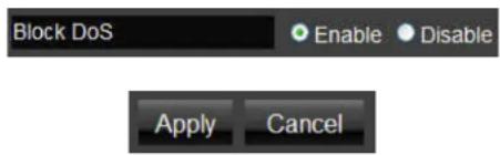
To enable blocking of denial of service (DoS) attacks, select the DoS option in the Firewall section.
DoS attacks can flood the internet connection with the continuous transmission of data. Blocking these attacks ensures that the internet connection is always available.
WAN Settings
Block DoS Enable or disable blocking DoS attacks.
Click Apply to save the settings or Cancel to discard changes.
6.6 Virtual Private Network Setup
A Virtual Private Network (VPN) provides a secure connection between two remote locations or two users over the Internet. It provides authentication to securely encrypt data communicated between the two remote endpoints. The ESR600H/ESR750H supports up to 5 VPN tunnels, making it ideal for small-office and home-office (SOHO) users.

Note:
It is highly recommended to start with the Wizard to establish VPN tunnels. If you are an advanced user and would like to manually configure VPN Settings, select Profile Setting for advanced VPN setting.
6.6.1 Viewing Status
View the status of currently configured VPN tunnels.
• No. The sequence number of the VPN tunnel.
• Name The name of the VPN tunnel.
• Type The type of VPN tunnel.
- Gateway/Peer IP Address The VPN gateway or peer IP address.
• Transmit Packets The number of packets transmitted.
• Received Packets The number of packets received.
- Uptime The amount of time the VPN has been active.
- Select Indicates the device(s) that can have actions performed on them.

6.6.2 Using the Virtual Private Network Wizard
The virtual private network (VPN) wizard guides the administrator through setting up a VPN over four different connection methods.
The VPN setup wizard introduction screen.
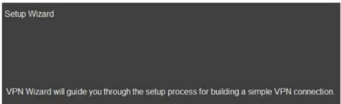
Click Next to continue.
Create a name for the VPN tunnel in the Name field.
Next

BASIC NETWORK SETTINGS
Click Back to return to the previous step;
Click Next to continue with the setup;
Click Cancel to stop the setup.
Select the type of VPN connection method to setup.
Back Next Cancel
Step2: VPN Connection Type
Please choose VPN connection type
L2TP
Choose this if you are using L2TP client for connection
PPTP
Choose this if you are using PPTP client for connection
L2TP
- User Name Enter the user name used to connect to L2TP server
- Password Enter the password used to connect to L2TP server
VPN Server IP Settings
- Server IP Enter an IP address which is different from the router's LAN IP address.
For example: ESR600H/ESR750H default IP: 192.168.0.1 Configure the IP address as 10.0.174.45
- Remote IP Range Enter an IP range under the same subnet as the above server IP.
For example: Server IP address is 10.0.174.45 Remote IP range is 10.0.174.66 – 100
IMPORTANT:
The remote IP range should not include the server IP address to avoid a network conflict.
Click Back to return to the previous step.
Click Next to continue with the setup.
Click Cancel to stop the setup.


BASIC NETWORK SETTINGS
If the setup is successful, the following screen is displayed. To enable the VPN policy immediately, click the check box.

Click Back to return to the previous step.
Click Apply to save the settings and continue.
Click Cancel to stop the setup.
Back Apply Cancel
PPTP
- User Name Enter the user name used to connect to the PPTP server.
- Password: Enter the password used to connect to the PPTP server.
VPN Server IP Settings
- Server IP: Enter an IP address which is different from the router's LAN IP address.
For example: ESR600H/ESR750H default IP: 192.168.0.1 Configure the IP address as 10.0.174.45
- Remote IP Range: Enter an IP range under the same subnet as the above server IP.
For example: Server IP address is 10.0.174.45 Remote IP range is 10.0.174.66 – 100
IMPORTANT:
The remote IP range should not include the server IP address to avoid a network conflict.
Click Back to return to the previous step.
Click Next to continue with the setup.
Click Cancel to stop the setup.


BASIC NETWORK SETTINGS
If the setup is successful, the following screen is displayed. To enable the VPN policy immediately, click the check box.

Click Back to return to the previous step.
Click Apply to save the settings and continue.
Click Cancel to stop the setup.
Back Apply Cancel
6.6.3 Configuring a VPN Tunnel Profile
Manually configure a VPN tunnel profile.
Click Add to begin creating a new VPN tunnel profile.
On the General tab, enter the following information:
• Name The name of the VPN tunnel profile.
- Connection Type: Select a connection type.

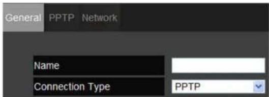
PPTP
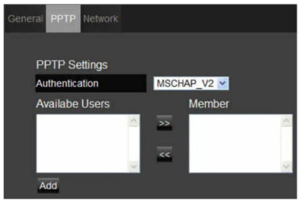
On the PPTP tab, enter the following information:
- Authentication There are three authentication algorithms: Select CHAP, PAP, or MSCHAP_V2.
- Available Users/Member Displays created users from the User Settings available to connect to PPTP server. Select the users in the list to include in the VPN tunnel, then click >> to add users to the Member field. Click << if you want to remove users from the Member box.
Click Add to manually add available users.
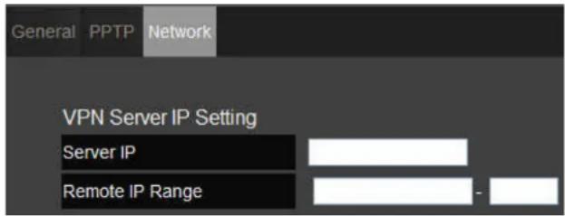
On the Network tab, enter the following information:
VPN Server IP Setting
- Server IP Enter an IP address which is different from the router's LAN IP address.
For example: the default LAN IP of the ESR600H/ESR750H is 192.168.0.1. set the server IP address as 10.2.2.1. - Remote IP Range Enter an IP range under the same subnet of the above server IP.
For example: if the server IP address is 10.2.2.1, create a remote IP range of 10.2.2.10 - 20.
Remote IP range is 10.0.174.66 - 100
IMPORTANT:
The remote IP range should not include the server IP address to avoid a network conflict.
Click Apply to save the settings or Cancel to discard changes.

L2TP
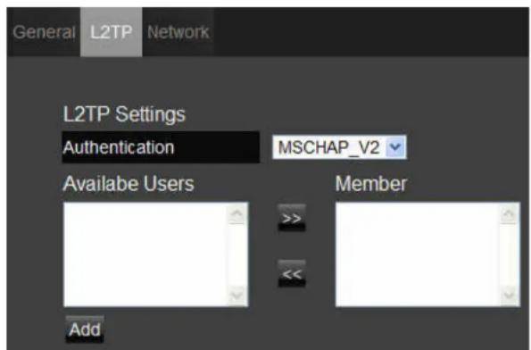
On the L2TP tab, enter the following information:
- Authentication: there are three authentication algorithms. Please select CHAP, PAP, or MSCHAP_V2.
- Available Users/Member: The users who you created in the User Setting to connect to L2TP server will be displayed. Select the users in the list who you wish to include in the VPN tunnel, and click the forward arrow to then add them to the Member Box. Click the backward arrow if you want to remove users from the Member box.
Click Add to manually add available users.
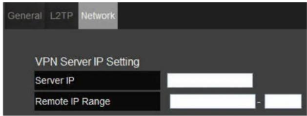
On the Network tab, enter the following information:
VPN Server IP Setting
- Server IP: enter an IP address which is different from your router's LAN IP address.
For example:
If the LAN IP of the ESR600H/ESR750H is 192.168.0.1, configure the server IP address as 10.2.2.1.
- Remote IP Range: enter an IP range under the same subnet of the above server IP.
For example:
If the server IP address is 10.2.2.1, configure a remote IP range of 10.2.2.10 - 20.
IMPORTANT:
The remote IP range should not include the server IP address to avoid a network conflict.
Click Apply to save the settings or Cancel to discard changes.

6.6.4 Configuring a User Profile
To manually setup a VPN tunnel, create a user profile and then a VPN profile.
Creating a User Profile
- Name Enter the name to connect to an L2TP or PPTP VPN tunnel.
- Password Enter the password to connect to an L2TP or PPTP VPN tunnel.
- Confirm Enter the password again to confirm the password entered above.
Click Add to add a user to the VPN user table or Reset to discard changes.
Table of Current VPN Users
Click Delete Selected to remove selected devices from the list.
Click Delete All to remove all devices form the list.
Click Reset the discard changes.
Click Apply to save the settings or Cancel to discard changes.


6.7 Advanced Network Settings
6.7.1 NAT Setup
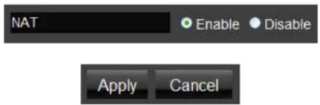
Network address translation (NAT) allows users on the LAN to access the Internet through a single Public IP Address or multiple Public IP Addresses. NAT provides firewall protection from hacker attacks and allows for mapping LAN IP addresses to WAN IP addresses with key services such as websites, FTP, video game servers, etc.
Click Enable or Disable to activate or deactivate the NAT.
Click Apply to save the settings or Cancel to discard changes.
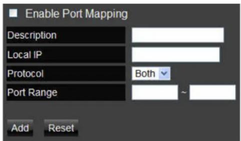
Port Mapping allows you to redirect a particular range of service port numbers from the WAN to a particular LAN IP address.
- Enable Port Mapping Click Enable Port Mapping to activate port mapping.
- Description Enter notes or details about the mapped port range configuration.
- Local IP Enter the local IP address of the server behind the NAT firewall.
- Protocol Select the protocol to use for mapping from the following: TCP, UDP or Both.
- Port Range Enter the range of ports to be forwarded.
Click Add to append a new device to the list or Reset to discard changes.
Current Port Mapping Table
Displays a list of mapped port ranges in use on the network.
• No. The sequence number of the mapped port range.
- Description Notes or details about the mapped port range.
- Local IP IP address of the server for the mapped port range.
- Type The protocol used to communicate with the WAN ports and LAN server.
- Port Range The range of mapped ports.
- Select Indicates the device(s) that can have actions performed on them.
Click Delete Selected to remove selected devices from the list.
Click Delete All to remove all devices form the list. Click Reset the discard changes.
Click Apply to save the settings or Cancel to discard changes.


6.7.3 Port Forwarding Setup
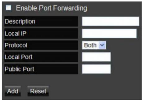
Port forwarding enables multiple server applications on a LAN to serve clients on a WAN over a single WAN IP address. The router accepts incoming client packets, filters them based on the destination WAN, or public, port and protocol and forwards the packets to the appropriate LAN, or local, port. Unlike the DMZ feature, port forwarding protects LAN devices behind the firewall.
- Enable Port Forwarding Click Enable Port Forwarding to active port forwarding.
- Description Enter notes or details about the forwarded port configuration.
- Local IP Enter the local IP address of the server behind the NAT firewall.
- Protocol Select the protocol to use for mapping from the following: TCP, UDP or Both.
- Local Port Enter the LAN port number that WAN client packets will be forward to.
- Public Port Enter the WAN port number that clients will send their packets to.
Click Add to append a new configuration to the table or Reset to discard changes.
ADVANCED NETWORK SETTINGS
PORT FORWARDING SETUP
Current Port Forwarding Table
The table of current port forwarding configurations.
Click Delete Selected to remove selected devices from the list.
Click Delete All to remove all devices form the list.
Click Reset the discard changes.
Click Apply to save the settings or Cancel to discard changes.


6.7.4 Port Triggering Setup
Some applications, such as online games, videoconferencing and VoIP telephony, require multiple ports for inbound and outbound traffic. If an application requires both an incoming and an outgoing port simultaneously, it is possible to configure static port forwarding to handle the packets. That is not an optimal solution because a static IP address must be configured for each device. With port triggering an application, local port or range of ports and a communication protocol can be mapped to a specific public port. Sending packets out over the local port triggers the router to open an incoming local port that is mapped to the same public port and application as the outgoing local port(s). The local application can communicate over the incoming and outgoing ports without the need for creating a fixed address.
- Enable Port Triggering Click Enable Trigger Port to activate port triggering.
- Description Enter notes or details about the port triggered configuration.
- Popular Applications Select a default application or add a new one.
- Trigger Port Enter the application's outbound port number(s).
- Trigger Type Select the protocol to use for port triggering from the following: TCP, UDP or Both.
- Public Port Enter the inbound port(s) for the application in the following format: 2300-2400 or 47624.
- Public Type Select the protocol to use for the inbound port from the following: TCP, UDP or Both.
Click Add to append a new configuration to the table or Reset to discard changes.

Current Port Triggering Table
The list of current port triggering configurations.
Click Delete Selected to remove selected devices from the list.
Click Delete All to remove all devices form the list.
Click Reset the discard changes.
Click Apply to save the settings or Cancel to discard changes.


6.7.5 Application Layer Gateway Setup
The ALG (Application Layer Gateway) serves as a window between correspondent application processes so that they may exchange information on an open environment.
Select the listed applications that need ALG support and then the router will authorize them to pass through the NAT gateway.
| Description | Select |
| H323 | |
| MMS | |
| TFTP | |
| Egg | |
| IRC | |
| Amanda | |
| Quake3 | |
| Talk | |
| IPsec | |
| FTP | |
| SIP | |
| RTSP |
Click Apply to save the settings or Cancel to discard changes.

6.7.6 Universal Plug and Play Setup
UPnP helps internet devices, such as gaming and videoconferencing, to access the network and connect to other registered UPnP devices.
Click Enable or Disable to activate or deactivate UPnP.
Click Apply to save the settings or Cancel to discard changes.

6.7.7 Internet Group Multicast Protocol Setup
Internet Group Multicast Protocol (IGMP) is a network-layer protocol used to establish membership in a multicast group.
Click Enable or Disable to activate or deactivate IGMP.
Click Apply to save the settings or Cancel to discard changes.


6.7.8 Quality of Service Setup
QoS can prioritize bandwidth use such as video streaming, online gaming, VoIP telephony and videoconferencing to ensure stable and efficient network performance.
Total Bandwidth Settings
Uplink Select the maximum bandwidth speed for outbound traffic.
Downlink Select the maximum bandwidth speed for inbound traffic.
Note:
Click Disabled if you do not want to prioritize any data or protocol.

Priority Queue
Set network resource usage based on specific protocols or port ranges. Incoming packets are processed based on the protocols' position within the queue.
Unlimited Priority Queue
- Local IP Address Enter the local IP address of a device on the network. This device's activity is not restricted by the QoS feature.
- High/Low Priority Queue: Specify the priority for different protocols. Additional protocols and port ranges can be added.
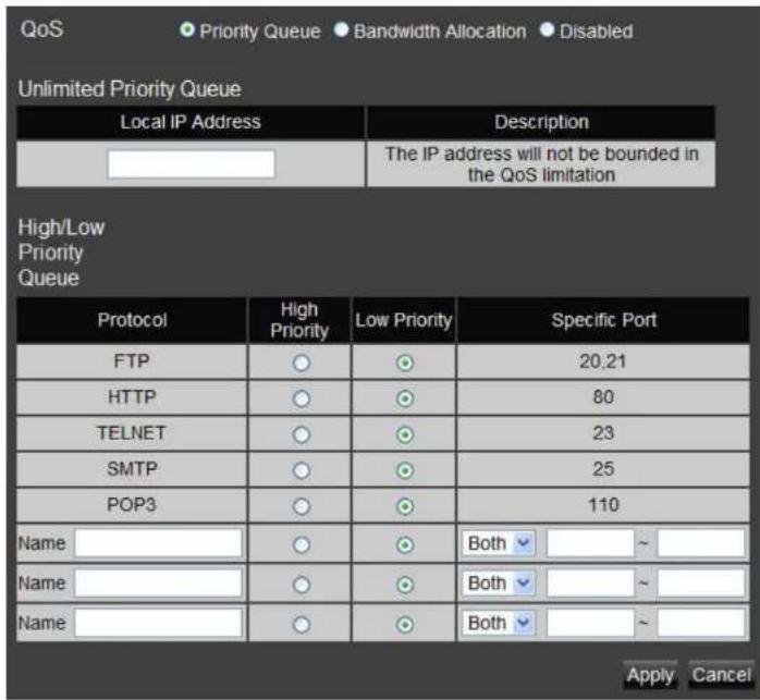
Bandwidth Allocation
Set network resource usage, for inbound and outbound traffic, based on local IP and port ranges.
- Type Select Download or Upload to specific the direction of packet traffic.
- Local IP Range Enter the local IP range of the current configuration.
- Protocol Select the protocol to manage for the current configuration.
- Port Range Enter the local port range of the current configuration.
- Policy Select Min or Max to specify the type of configuration policy.
- Rate (bps): Select the bandwidth rate, in bits per second (bps), of the current configuration.
Click Add to save the settings and list the configuration in the Current QoS table or Reset the discard changes.
Click Apply to save the settings or Cancel to discard changes.
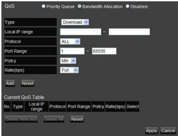


ADVANCED NETWORK SETTINGS
ROUTING SETUP
6.7.9 Routing Setup
Typically static routing does not need to be setup because the ESR600H/ESR750H has adequate routing information after it has been configured for Internet access. Static routing is only necessary if the router is connected to network under a different subnets.

Note:
To enable a static routing, NAT must be disabled.
NAT Disabled
Click Enable or Disable to activate or deactivate Static Routing.

NAT Enabled
If the router is connected with a network under the different subnet, the routing setup allows the network connection within two different subnets.
- Enable Static Routing Click Enable Static Routing to activate the feature.
- Destination LAN IP Enter the LAN IP address of the destination device.
- Subnet Mask Enter the Subnet Mask of the destination device.
- Default Gateway Enter the default gateway IP address for the destination device.
- Hops Enter the maximum number of hops within the static routing that a packet is allowed to travel.
Click Add to save the settings and list the configuration in the Current Static Routing table or Reset the discard changes.
Click Apply to save the settings or Cancel to discard changes.
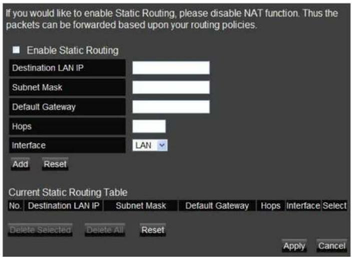

6.7.10 Wake on LAN Setup
Wake on LAN setup (WOL) allows the administrator to activate a computer over the network.
Enable WOL over WAN Click Enable WOL over WAN to activate the feature.
Server Port Enter the server port of the device to activate.
Wake MAC Address Enter the MAC address of the device to activate. Click Start to activate the device.
Click Apply to save the settings or Cancel to discard changes.
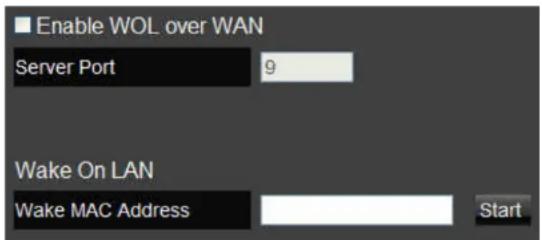
6.7.11 USB Port Setup
The USB Port feature allows the router to be used as a file server or a virtual USB port on a local device. To enable NetUSB mode, the Control Center software must be installed on the intended device. For more information about the ESR600H/ESR750H's wireless services, refer to "USB Services" on page 7-0.
USB Access Mode
- Access Mode Select Server Mode or NetUSB Mode.
- Server Name Enter the name of the Samba server.
• Workgroup Enter the name of the Windows workgroup. - Description (optional) Enter an optional description of the server.
- Administrator Enter the administrator's user ID.
- New Password Enter a new administrator password.
- Confirm Password Enter the administrator's password again for confirmation.
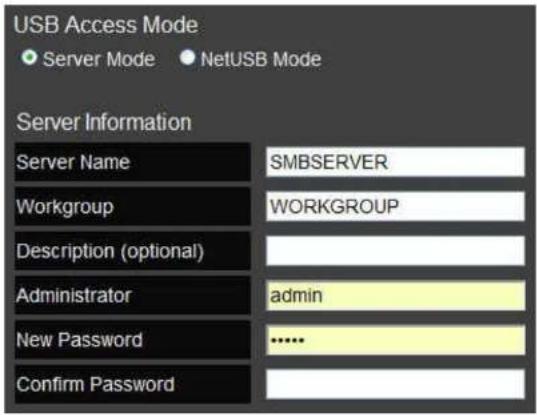
ADVANCED NETWORK SETTINGS
USB PORT SETUP
NetUSB Mode
Server Mode Click Server Mode to enable the router's USB port as a server.
NetUSB Mode Click NetUSB Mode to enable the router's USB port as a virtual, local USB port.
Click Apply to save the settings or Cancel to discard changes.


6.8 Tools Setup
6.8.1 Configuring the Administrator Account
Change the router's system password as well as setup a device to remotely configure the settings.
- Old Password: Enter the existing administrator password.
- New Password: Enter the new administrator password.
- Repeat New Password: Re-type the new administrator password.
Remote Management
- Host Address: Enter the designated host IP Address.
- Port: Enter the port number (Default: 8080) for remote accessing management web interface.
- Enable: Select to enable remote management.
Click Apply to save the settings or Cancel to discard changes.


Note:
To access the settings of the ESR600H/ESR750H remotely, enter the router's WAN IP address and port number.
6.8.2 Configuring the Router's Time
Change the system time of the ESR600H/ESR750H and setup automatic updates through a network time protocol server (NTP).
- Time Setup Select how the router obtains the current time.
• Time Zone Select the time zone for the router. - NTP Time Server Enter the domain name or IP address of an NTP server.
- Enable Daylight Saving Click to enable or disable day-light savings time.
- Start Time Select the date and time when daylights savings time starts.
- End Time Select the date and time when daylights savings time ends.

6.8.3 Configuring Dynamic Domain Name Service
Dynamic domain name service (DDNS) allows the administrator to map a static domain name to a dynamic IP address. A DDNS service provider, such as DynDNS, ZoneEdit or CyberGate, must provide an account, password, and static domain name to use this feature. DDNS particularly benefits end users that have their own websites or FTP sites.
• Dynamic DNS Enable or Disable DDNS.
• Server Address Select the DDNS Server Address.
- Host Name Enter the DDNS provider static domain name.
- Username Enter the username given by the DDNS provider.
- Password Enter the password given by the DDNS provider.

6.8.4 Diagnosing a Network Connection
The diagnosis feature allows the administrator to verify that another device is available on the network and is accepting request packets. If the ping result returns alive, it means a device is on line. This feature does not work if the target device is behind a firewall or has security software installed.
- Address to Ping Enter IP address of the device to ping.
- Ping Result View the result message from the ping test.

6.8.5 Upgrading Firmware
Firmware is system software that operates and allows the administrator to interact with the router.

WARNING!
Upgrading firmware through a wireless connection is not recommended. Firmware upgrading must be performed while connected to an Ethernet (LAN port) with all other clients disconnected.
To update the firmware version, follow these steps:
- Download the appropriate firmware approved by EnGenius Networks from an approved web site.
- Click Choose File.
- Browse the file system and select the firmware file.
- Click Apply.
You can upgrade the firmware of the router in this page. Ensure, the firmware you want to use is on the local hard drive of your computer. Click on Browse to browse and locate the firmware to be used for your update.
Choose File No file chosen
Apply Cancel
6.8.6 Backing Up Settings
Store multiple settings versions by saving the settings to a configuration file on the device.
- Restore to factory default Click Reset to restore the ESR600H/ESR750H to factory defaults.
- Backup Settings Click Save to save the current configuration on the ESR600H/ESR750H to a *.dlf file.
- Restore Settings To restore saved settings, do the following:
a. Click Choose File.
b. Browse the file system for location of the settings file (*.dlf).
c. Click Upload.

BASIC NETWORK SETTINGS
REBOOTING THE DEVICE
6.8.7 Rebooting the Device
This feature allows the administrator to reboot the router in the event of a system hang up.
Click Apply to reset the device.

USB Services
WIRELESS SERVICES
The ESR600H/ESR750H provides two ways to access USB devices over a network: server mode and NetUSB mode. In server mode, the router allows USB storage devices to act as a file servers which can be shared by users connected to the same network. In NetUSB mode, or USB over IP, the router allows users to connect to remote USB non-storage devices, such as speakers, on the same network.

7.1 USB Over IP
7.1.1 Using the USB Device Server
Introduction
NetUSB is a USB over IP technology that transparently redirects all USB packets to a TCP/IP network channel. The technology allows a USB device to be used as if it were connected directly to a PC when actually the USB device is remotely connected to the ESR600H/ESR750H Dual Concurrent Wireless Router.
Connect & Disconnect
Connecting to a USB device with the EnGenius USB Control Center simulates plugging a USB device into a PC. Similarly, disconnecting a USB device simulates unplugging a USB device from a PC. Once connected, the USB device can be used as if it were physically connected to the PC. Only one PC can connect to the USB device at a time so no other PC can connect this USB device until the USB device is disconnected.
Subnet Issue
In order for a PC to use the NetUSB technology, both the PC and USB device server must be on the same subnet. To determine the USB device server's subnet, open the Control Centre software let it search for available devices. All available USB device servers are listed in the control center. If a server is not on the same subnet as the PC, the server is highlighted in red. If the server is on the same subnet, it is highlighted in blue and can be used with NetUSB. To configure the USB device server to be on the same subnet as the PC, modify the device server's IP address to use the same subnet or switch the server to use DHCP mode.
Installation of a USB Device Driver
Some USB devices, like printers or multifunction printers (MFPs), require installing a vendor-supplied driver. For USB devices that do not need to a driver installed, skip this section.
To install a USB device driver, do the following:
- Insert the CDROM into the CDROM drive and run the "autorun" program.
- Follow the instructions of the installation program to install driver.
- When the installation program prompts to plug-in the USB device, run the Control Center.
- In the Control Center, click the USB device server that has the USB device attached.
- Click the USB device as in the following figure.

- Click Connect. The message Manually Connect by your_computer_name is shown, as the following figure.
![EnGenius USB Device Server Control Center System Tools About Configure Server Auto-Connect Printer Connect Disconnect Request to Connect Network Scanner ESR-750H - 192.168.1.220 Mass Storage - SanDisk Corporation - Cruzer Contour MFP - Hewlett-Packard - HP LaserJet 3052 [ Manually Connected by TEST ]](/content/2026/06/1254915/images/2578eec6e7a9df9176ff58e26a811d9c9d29e8ed0b0f779dc788e81a4792d876.jpg)
- The installation program detects the USB device and continues the installation.
- After the installation is complete, select the USB device in the Control Center and click Disconnect to disconnect the USB device.
The USB device driver has been successfully installed.
Using the USB Device Server
- In the Control Center, click the USB device server that has the USB device attached.
- Select the USB device.

- Click Connect. The message Manually Connect by your_computer_name is shown.
![EnGenius USB Device Server Control Center System Tools About Configure Server AutoConnect Packet Connect Request to Connect Disconnect Network Scanner ESR-750H - 192.168.1.220 Mass Storage - A-DATA - A-DATA USB Flash Drive [ Manually Connected by W/C2E8400 ]](/content/2026/06/1254915/images/029518c4fd23023b214ea20624d004b76b31f3a2b019aa6a0fe6f0d0d994ed29.jpg)
- The PC detects the USB device connection.
- Use the USB device as if it were connected directly to the PC's USB port.
- To finish using the USB device, Select the USB device in the Control Center and click Disconnect to disconnect the USB device. Other PCs can not connect to the USB device while it is in use by another PC.
7.1.2 Printer and Scanner Sharing
Auto-Connected Printers
The method described in the previous section, refer to “Using the USB Device Server” on page 7-5, demonstrated manually connecting and disconnecting to a virtual USB device. That procedure applies to USB storage devices but not to printers, scanners or multifunction printers (MFPs). For these devices, the USB device server supports auto-connect so users don’t need to manually connect and disconnect when using the USB device. The following instructions demonstrate how to use this feature.

Note:
A device driver must be installed for the USB device with the Control Centre for the auto-connect feature to work. Refer to “Installation of a USB Device Driver” on page 7-3.
To use the auto-connect feature, do the following:
- Connect the USB printer to the device server's USB port.
- Open the Control Centre software to perform a search of available devices.
- In the Control Center, select the USB device server that has the printer attached.
- Select the printer.
WIRELESS SERVICES
PRINTER AND SCANNER SHARING
- Click Auto Connect Printer.
![EnGenius USB Device Server Control Center System Tools About Configure Server Auto-Connect Printer Connect Disconnect Request to Connect Network Scanner + Set Auto-Connect Printer — Delete Auto-Connect Printer Mass Storage - SanDisk Corporation - Cruzer Contour MFP - Hewlett-Packard - HP LasesJet 3052 [ Manually Connected by TEST ]](/content/2026/06/1254915/images/10afe9718b2d24edb751d60e96df9e6ae19204b224fee434717f4fb123877dc3.jpg)
- Select Set Auto-Connect Printer on the context menu to display the Add to Auto-Connect Printer List dialogue.
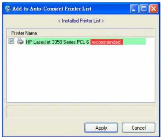

Note:
The selected printer in the dialogue must match the physical printer attached to the USB device server.
- Select a printer from the list.
-
Click Apply.
-
The printer is displayed in the list with the label Auto-Connected Printer in red.
![EnGenius USB Device Server Control Center System Tools About Configure Server Auto-Connect Printer Connect Disconnect Request to Connect Network Scanner ESR-750H - 192.168.1.220 Mass Storage - SanDisk Corporation - Cruzer Contour MFP - Hewlett-Packard - HP LaserJet 3052 [Auto-Connected Printer]](/content/2026/06/1254915/images/e842fbc581df80c2dadff0d7301a172d540624583a36d22169cf2e443c7746e9.jpg)
Viewing a List of Auto-Connected Printers
To view the list of auto-connected printers, do the following:
- Click the Tools menu item on the Control Centre.
- Click the Auto-Connect Printer List submenu item to display the Auto-Connect Printer List dialogue.

Removing a Printer from the Auto-Connect List
To remove a printer from the list, do the following:
- Click the Tools menu item on the Control Centre.
- Click the Auto-Connect Printer List submenu item to display the Auto-Connect Printer List dialogue.
- Select the printer to remove.
- Click Delete.
Printing to an Auto-Connected Printer

Note:
The Control Centre software must be running to issue a print job to an auto-connected printer.
Perform a print operation in the usual manner but make sure to select auto-connected printer in the software's printer options. The Control Centre manages the auto-connect operation with the USB device printer each time a print job is requested, so no manual intervention is required.
Configuring the Control Centre as a Windows Service

Note:
This feature is enabled by default.
The Control Centre must be running for a USB device printer to be available to PCs on the network. Instead of manually opening the software after every login, it is possible to configure the it as a Windows service.
To configure the Control Centre as a Windows service, do the following:
- Click the Tools menu item on the Control Centre.
- Click the Configuration submenu item to display the Control Centre - Configure dialogue.

- Click Automatically execute when logging on Windows.
- To complete the operation, do the following:
WIRELESS SERVICES
PRINTER AND SCANNER SHARING
- Click OK to save the settings and close the dialogue.
- Click Cancel to discard changes and close the dialogue.
- Click Apply to save the settings but keep the dialogue open.
Network Scanners
Scanning with a USB Scanning Device and NetUSB
To use a USB scanning device, do the following:
- Connect the USB scanner to the device server's USB port.
- Open the Control Centre software to perform a search of available devices.
- In the Control Center, select the USB device server that has the scanner attached.
- Select the scanner.
![EnGenius USB Device Server Control Center System Tools About Configure Server Auto-Connect Printer Connect Disconnect Request to Connect Network Scanner ESR-750H - 192.168.1.220 Mass Storage - SanDisk Corporation - Cruzer Contour MFP - Hewlett-Packard - HP LaserJet 3052 [Auto-Connected Printer] Auto](/content/2026/06/1254915/images/d414e91c18d0ac26cd9fb41dfec73c913f699ca138c232567af46c8cae889bbf.jpg)
WIRELESS SERVICES
PRINTER AND SCANNER SHARING
- Click Network Scanner to connect to the device and display the following dialogue.
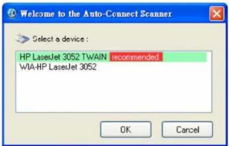
-
Select a scanner device in the list.
-
Click OK to display the scanner device configuration dialogue.

- Perform the scan operation.
- After the scan operation is complete, close the Auto-Connect Scanner dialogue (step 5).
- The Control Centre automatically disconnects the scanning device.
7.1.3 Storage
USB storage device must be manually connected. After you connecting to a USB storage device, the PC displays a new disk. If the USB storage device is a flash drive, the new disk is a displayed as a removable disk.
![EnGenius USB Device Server Control Center System Tools About Configure Server Auto-Connect Printer Connect Disconnect Request to Connect Network Scanner ESR-750H - 192.168.1.220 Mass Storage - SanDisk Corporation - Cruzer Contour [ Manually Connected by TEST ] MFP - Hewlett-Packard - HP LaserJet 3052 [ Auto-Connected Printer ]](/content/2026/06/1254915/images/1e31c823e53a419336870013517c0837e4de42ee7c78b6b347a66ddc0a960ba1.jpg)
The USB storage device can be viewed the system tray in the Remote Devices icon.

Remove the USB storage device in the usual manner.
WIRELESS SERVICES
STORAGE

In the Control Center, select the USB storage device and click Disconnect to disconnect the USB storage device.
Request to Connect
If a USB device is manually connected by another user, it can not be connected by another PC. There is a way to send a message to the PC using the device and request control. In the Control Centre, click Request to Connect to display the following dialogue.

A dialogue is displayed to the controlling PC requesting control of the storage device.

The controlling PC has the option to accept or reject the request. Click Accept to close the dialogue and relinquish control or Reject to keep control.
Quitting the Control Center
The Control Center does not close completely by clicking the system close button. The application windows disappears and closes to the system tray. There are two ways to completely close the Control Center. The first way is selecting the Exit submenu item in the File menu of the Control Center. The second way is right-clicking the icon of the Control Center in the system tray and selecting the Exit submenu item.
Limitations
There are some limitations to using the NetUSB technology.
- It supports Windows 2000/XP/2003/Vista and above.
- Only one PC can get the ownership of the same USB device at the same time.
7.1.4 shAir Music

Note:
The shAir Music feature is only available with the ESR750H model.
Using USB Speakers with shAir

Note:
If USB speakers are be detected by the iOS device, there is no need to use the Control Center software.
- Connect the USB speakers to the device server's USB port.
- Open the Control Centre software to perform a search of available devices.
- In the Control Center, select the USB device server that has the speakers attached.

- Select the USB speaker device.
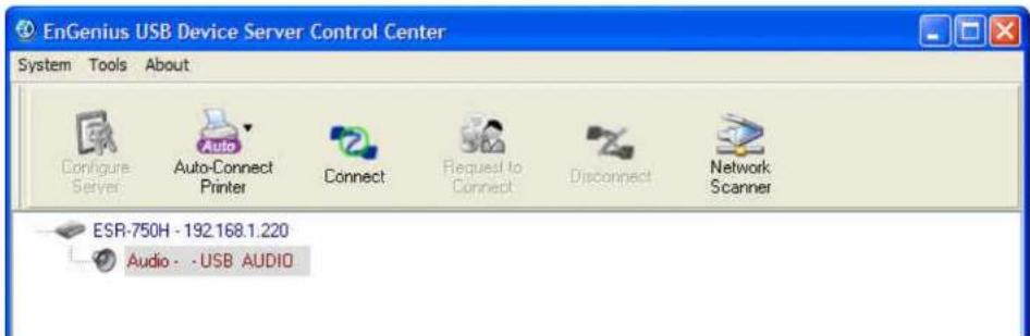
- Click Connect. The message Manually Connect by your_computer_name is shown.
![EnGenius USB Device Server Control Center System Tools About Configure Server Auto-Connect Printer Connect Request to Connect Disconnect Network Scanner ESR-750H - 192.168.1.220 Audio - -USB AUDIO [ Manually Connected by WIC2E8400 ]](/content/2026/06/1254915/images/bf68e6926c79c071b92cdb36f33a89bcd3ef1f9b81e73148510c73d9b285629a.jpg)
- The USB speaker device is available for use with iOS devices.
Play Music from iTunes
- Install iTunes 10, or later, on a Mac or PC that is connected to the same network as your shAir Music Server.
- Launch iTunes and click the AirPlay icon displayed in the lower right of the window and select your shAir Music device from the list.

natural_image
Computer monitor interface with navigation buttons and a play button (no text or symbols on icons)- Choose a song and click play in iTunes.
- The music will stream to your shAir Music Server.
Multiple Speakers
You can easily stream music from iTunes to multiple speakers in your home.
- Click the AirPlay icon and select Multiple Speakers from the list.
- Click the speakers you want to use.
![Multiple Speakers Master Volume My Computer This Computer YDENON:[AVR-3311CI] AirPlay Device](/content/2026/06/1254915/images/b6ba11e78ffbf6fde81a84e4b254ba96f387a3469140c9901207ce6fed5b1452.jpg)
Figure 7-1. shAir Music Server Connected to iTunes
Streaming Music Stored from an iOS Device Directly to the shAir Music Server
If you update your "iPhone/iPod touch/iPad" to iOS 4.2.1 or later, you can stream music stored in your "iPhone/iPod touch/iPad" directly to your shAir Music Server.
1. Tap the AirPlay icon

WIRELESS SERVICES
SHAIR MUSIC
- Select the speaker you want to use.

7.2 Samba
This chapter describes the file server function which allows USB storage devices to be shared across a network by using SMB: NetBIOS over TCP/IP protocol.
Preliminary
- This product supports file formats FAT12/16/32 and NTFS. The NTFS write operation is only supported in NetUSB mode.
- EnGenius Networks is not responsible for the loss or corruption of data in memory devices, including hard disks; EnGenius Networks is not responsible for the leaking, manipulation, loss, or corruption of data in memory devices connected to the Server after unauthorized access.
- In order to use the USB Mass Storage device connected to the server, the USB device must be turned on.
Connecting USB Mass Storage to the Server
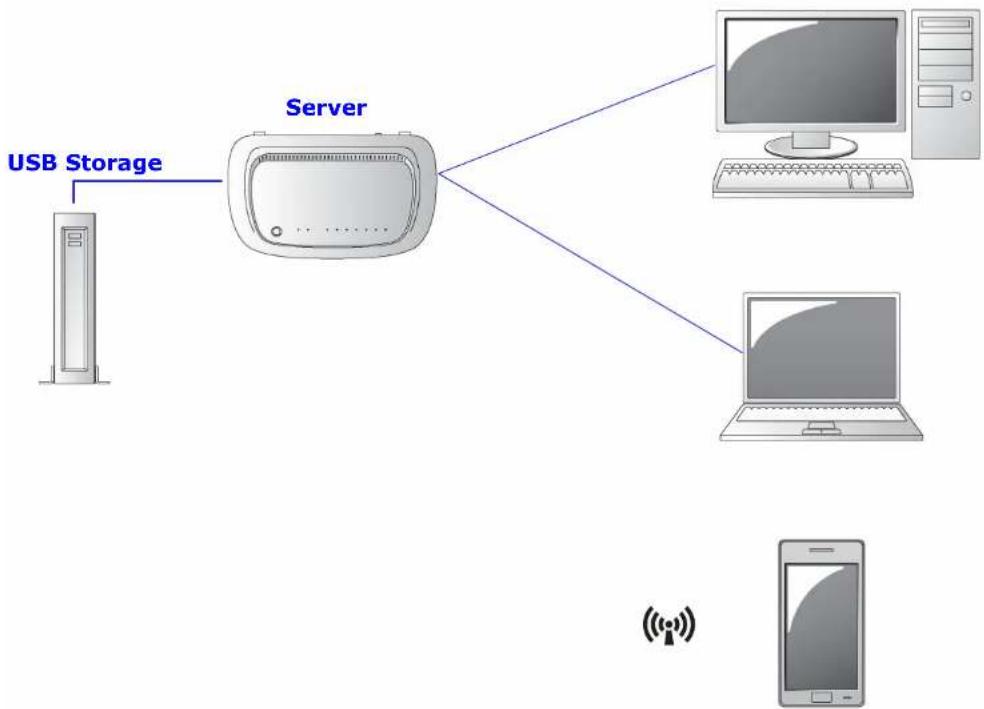
flowchart
graph TD
    A["USB Storage"] --> B["Server"]
    B --> C["Desktop Computer"]
    B --> D["Laptop"]
Supported Codepages
What is Codepage?
Used by the system to encode and interpret string characters. Codepage formats are not the same for each language. Some languages, such as Japanese have multibyte characters, while others, such as English and German, need only one byte to represent each character.
Filename Encoding of FAT File System
This is known as an 8.3 file name, a short file name using codepage encoding. The FAT file system also supports file names that can be up to 255 characters long. This is known as a long file name using Unicode (UTF-16) encoding.
When do You Need to Configure Codepage?
The Server supports Windows codepages. If users want to communicate files using SMB on Windows 98/Me/2000 with the Server, they have to set their Server codepage to be same as the codepage that their Windows PC is using.
Configuring the Server's Codepages
Users can use the following methods to set the Server's codepage.
- Start Control Center and Auto-searching Server window will appear.
- If the tool finds the Servers in your local area network, select the Server from the Server List and click "Configure Server" button.
- The Web manager will show, click Config button and enter the server administrator username (default: admin) and password (default: admin).
- After you have logged in successfully, setting General configuration dialog appears.
- Select your codepage form File Server Codepage box and click Apply.
Using Shared Storage by USB Server Mode for Windows
- Connect a USB storage device to this product.
- Select My Network Places.
- Click Display the Computers of Workgroup.
- Double click the Microsoft Windows Network icon.
- Double click the Workgroup that the Server belongs to. The default Workgroup name is "WORKGROUP". You can refer to Control Center or the Server's web pages to get it. You will see that the Server is displayed as its server name.
- If you cannot find Workgroup name of the Server in Microsoft Windows Network, you can select Search for Computer... in My Network Places and enter the Server Name of the Server to find it.
- Double click this Server Name icon.

Note:
If you use SMB on Windows 98 SE/ME, you must login to your Windows 98 SE/ME using the same user name as in the Server's User Account.
- The shared folders will be listed as sdax where x represents the x-th disk with respect to the USB port.
- Perform Open, Paste, Remove or Copy the files to the shared folders.
Appendix A
Federal Communication Commission Interference Statement
This equipment has been tested and found to comply with the limits for a Class B digital device, pursuant to Part 15 of the FCC Rules. These limits are designed to provide reasonable protection against harmful interference in a residential installation. This equipment generates uses and can radiate radio frequency energy and, if not installed and used in accordance with the instructions, may cause harmful interference to radio communications. However, there is no guarantee that interference will not occur in a particular installation. If this equipment does cause harmful interference to radio or television reception, which can be determined by turning the equipment off and on, the user is encouraged to try to correct the interference by one of the following measures:
- Reorient or relocate the receiving antenna.
- Increase the separation between the equipment and receiver.
- Connect the equipment into an outlet on a circuit different from that to which the receiver is connected.
- Consult the dealer or an experienced radio/TV technician for help.

WARNING!
Any changes or modifications not expressly approved by the party responsible for compliance could void the user's authority to operate this equipment.
This device complies with Part 15 of the FCC Rules. Operation is subject to the following two conditions: (1) This device may not cause harmful interference, and (2) this device must accept any interference received, including interference that may cause undesired operation.
FCC Radiation Exposure Statement

Important:
This equipment complies with FCC radiation exposure limits set forth for an uncontrolled environment. This device complies with FCC RF Exposure limits set forth for an uncontrolled environment, under 47 CFR 2.1093 paragraph (d)(2).
This transmitter must not be co-located or operating in conjunction with any other antenna or transmitter.
Appendix B
Industry Canada Statement
This device complies with RSS-210 of the Industry Canada Rules. Operation is subject to the following two conditions: (1) This device may not cause harmful interference, and (2) this device must accept any interference received, including interference that may cause undesired operation.
Radiation Exposure Statement:
This equipment complies with IC radiation exposure limits set forth for an uncontrolled environment. This equipment should be installed and operated with minimum distance 20cm between the radiator & your body.
There are different ways of connecting your personal computer (PC) or mobile computing device to the Internet. Here are four of the most common ways and how to connect to the Internet using them.
Dynamic IP Address (DHCP)
A DHCP of connection is where your internet connection is usually always on and your internet service provider automatically provides you with an IP address. A DHCP connection is usually from a Cable internet service.
Static IP
To set up a Static IP connection, enter the following: IP Address of the Internet Connection, Subnet Mask, Default Gateway, and both DNS Servers. This information can be obtained by either your Internet Service provider or Network Administrator. If your internet service provider requires a username and password to connect, you will then be prompted to enter the correct information.
MTU: Maximum Transmission Unit. It specifies the largest packet size permitted for internet transmission. The factory default MTU size of Static IP is 1500. If you wish to manually change the MTU size, set it between 512 and 1500.
Point-to-Point Protocol over Ethernet (PPPoE)
Point-to-Point Protocol over Ethernet (PPPoE): To set up a PPPoE connection, enter the Username, Password, and Service (name) of the internet connection provided by your ISP. Click Next and the ESR300H should connect to the internet successfully. A PPPoE connection is usually from a DSL internet service.
- Login: The username or e-mail address that the internet connection uses to access internet connectivity.
- Password: The password that corresponds to the username or e-mail address used to connect to the internet in the PPPoE.
- Service Name: The Service Name is optional. This is to signify the name of the Internet Service Provider.
- MTU: Maximum Transmission Unit. It specifies the largest packet size permitted for internet transmission. The factory default MTU size of Static IP is 1500. If you wish to manually change the MTU size, set it between 512 and 1500.
- Point-to-Point Tunneling Protocol (PPTP)
To set up a PPTP connection, enter the type of WAN connection (Static IP or DHCP). After, depending on the type of WAN, follow the instructions of DHCP or Static IP to fill out the corresponding information. Then, proceed to enter the Username, Password, Service, and Connection ID of the PPTP internet connection. Once completed, click Next. Once configured, the internet connection will successfully connect.
Layer 2 Tunneling Protocol (L2TP)
To set up an L2TP connection, enter the type of WAN connection (Static IP or DHCP). After, depending on the type of WAN, follow the instructions of DHCP or Static IP to fill out the corresponding information. Then, proceed to enter the Username, Password, and Service. Click next when completed. Once configured, the internet connection will successfully connect.
MTU: Maximum Transmission Unit. It specifies the largest packet size permitted for internet transmission. The factory default MTU size of Static IP is 1500. If you wish to manually change the MTU size, set it between 512 and 1500.
Appendix D
WorldWide Technical Support
| REGION/COUNTRY OF PURCHASE | SERVICE CENTRE | SERVICE INFORMATION |
| Canada | CANADA web site | www.engeniuscanada.com |
| rma@engeniuscanada.com | ||
| contact numbers | Toll-Free:(+1)888-397-2788Local: (+1)905-940-8181 | |
| hours of operation | Monday - Friday9:00AM to 5:30PM (GMT-5) | |
| USA | LOS ANGELES, USA web site | www.engeniustech.com |
| support@engeniustech.com | ||
| forum | www.engeniusforum.com | |
| contact numbers | Toll-Free: (+1) 888-735-7888ext.518Local: (+1) 714-432-8668 | |
| hours of operation | Monday - Friday8:00 AM to 5:30 PM PST (GMT-8) |
| REGION/COUNTRY OF PURCHASE | SERVICE CENTRE | SERVICE INFORMATION | |
| Mexico, Central and South America | MIAMI, USA web site | www.senaousa.com | |
| fae@senaousa.com | |||
| forum | www.engeniusforum.com | ||
| contact numbers | Miami: (+1) 305-592-5666Sao Paulo, Brazil: (+55)11-3957-0303D.F., Mexico:(+52)55-1163-8894 | ||
| hours of operation | Monday - Friday8:00 AM to 5:30PM EST (GMT-5) | ||
| Singapore, Cambodia, Indonesia,Malaysia, Thailand, Philippines, VietnamChina, Hong Kong, Korea,IndiaSouth AfricaEuropeOceania | SINGAPORE web site | www.engeniustech.com.sg | |
| techsupport@engeniustech.com.sg | |||
| contact numbers | (+65) 6227 1088 | ||
| hours of operation | Monday - Friday9:00 AM - 6:00 PM (GMT+8) | ||
| Africa | DUBAI, UAE web site | www.engenius-me.com | |
| Middle East | support@engenius-me.com | ||
| Russia | contact | (+971) 4357 5599 | |
| CIS / Armenia, Azerbaijan, Balerus, Georgia, Kazakhstan, Kyrgyzstan, Moldova, Tajikistan, Turkmenistan, Ukraine, Uzbekistan Turkey | numbers | ||
| hours of operation | Monday - Friday 9:00 AM - 5:00 PM (GMT+4) | ||
| Afghanistan | |||
| Pakistan | |||
| Bangladesh, Maldives, Nepal, Sri Lanka | |||
| Other | TAIWAN web site | www.engeniusnetworks.com | |
| technology@senao.com |
Note:
* Service hours are based on the local time of the service center.
* Please visit the regional website for the customer service latest information.
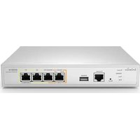
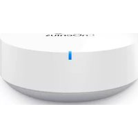
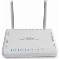
- TABLE OF CONTENTS
- Product Overview
- Installation
- EnGenius Quick Start
- Web Configuration
- Installation Setup Wizard
- Basic Network Settings
- USB Services
- Appendix A
- Appendix B
- Appendix C
- Appendix D
- Conventions
- General Conventions
- CAUTION!
- WARNING!
- Important:
- Note:
- Example:
- N/A:
- Prerequisite:
- Typographical Conventions
- Bold
- Copyright
- Product Overview
- Features
- Package Contents
- Product Layout
- System Requirements
- Wall Mounting
- Installing the Software
- Setup Notes
- Connecting Network Cables
- Logging In
- Viewing the Dash Board
- Services
- Home
- Setup Wizard
- Network Settings
- Language
- Logout
- Web Menus Overview
- System
- Internet
- Wireless 2.4G
- Wireless 5G
- Firewall
- Virtual Private Network
- Advanced
- Tools
- Detecting the Internet Connection
- System Setup
- Viewing System Status
- WAN Settings
- LAN Settings
- Wireless 2.4G Setting
- Wireless 5G Setting
- Configuring LAN
- LAN IP
- DHCP Server
- DNS Server
- Configuring DHCP
- DHCP Client Table
- Enable Static DHCP IP
- Current Static DHCP Table
- Configuring Logging
- Log Message List
- Monitoring Bandwidth Usage
- Configuring Languages
- Configuring WAN Settings
- View WAN Status
- Configuring Dynamic IP
- Dynamic IP
- DNS Servers
- Configuring Static IP
- Static IP
- Configuring PPPoE
- Configuring PPTP
- WAN Interface Settings
- Dynamic IP Address
- Static IP Address
- PPTP Settings
- Configuring L2TP
- L2TP Settings
- Wireless 2.4G LAN Setup
- Configuring Basic Settings
- Access Point Mode
- Wireless Distribution System Mode
- WDS Security Settings Screen
- Wired Equivalent Privacy (WEP)
- Wi-Fi Protected Access (WPA) Pre-Shared Key
- Configuring Advanced Settings
- Configuring Security
- Encryption Type
- Encryption: Wi-Fi Protected Access (WPA) Pre-Shared Key
- Encryption: WPA RADIUS
- Configuring Filter
- Enable Wireless Access Control
- MAC Address Filtering Table
- Configuring Wi-Fi Protected Setup
- Configuring Client List
- Wireless LAN 5G Setup
- Configuring Basic Settings
- Configuring Advanced Settings
- Configuring Security
- Configuring Filters
- Configuring Wi-Fi Protected Setup
- Configuring Client List
- Firewall Setup
- Configure Basic Settings
- Configuring Advanced Settings
- Configuring Demilitarized Zone
- Configuring Denial of Service
- Virtual Private Network Setup
- Viewing Status
- Using the Virtual Private Network Wizard
- L2TP
- VPN Server IP Settings
- PPTP
- Configuring a VPN Tunnel Profile
- VPN Server IP Setting
- Configuring a User Profile
- Creating a User Profile
- Table of Current VPN Users
- Advanced Network Settings
- NAT Setup
- Current Port Mapping Table
- Port Forwarding Setup
- Current Port Forwarding Table
- Port Triggering Setup
- Current Port Triggering Table
- Application Layer Gateway Setup
- Universal Plug and Play Setup
- Internet Group Multicast Protocol Setup
- Quality of Service Setup
- Total Bandwidth Settings
- Priority Queue
- Unlimited Priority Queue
- Bandwidth Allocation
- Routing Setup
- NAT Disabled
- NAT Enabled
- Wake on LAN Setup
- USB Port Setup
- USB Access Mode
- NetUSB Mode
- Tools Setup
- Configuring the Administrator Account
- Remote Management
- Configuring the Router's Time
- Configuring Dynamic Domain Name Service
- Diagnosing a Network Connection
- Upgrading Firmware
- Backing Up Settings
- Rebooting the Device
- USB Over IP
- Using the USB Device Server
- Introduction
- Connect & Disconnect
- Subnet Issue
- Installation of a USB Device Driver
- Using the USB Device Server
- Printer and Scanner Sharing
- Auto-Connected Printers
- Viewing a List of Auto-Connected Printers
- Removing a Printer from the Auto-Connect List
- Printing to an Auto-Connected Printer
- Configuring the Control Centre as a Windows Service
- WIRELESS SERVICES
- Network Scanners
- Scanning with a USB Scanning Device and NetUSB
- Storage
- Request to Connect
- Quitting the Control Center
- Limitations
- shAir Music
- Using USB Speakers with shAir
- Play Music from iTunes
- Multiple Speakers
- Streaming Music Stored from an iOS Device Directly to the shAir Music Server
- Tap the AirPlay icon
- Samba
- Preliminary
- Connecting USB Mass Storage to the Server
- Supported Codepages
- What is Codepage?
- Filename Encoding of FAT File System
- When do You Need to Configure Codepage?
- Configuring the Server's Codepages
- Using Shared Storage by USB Server Mode for Windows
- Federal Communication Commission Interference Statement
- FCC Radiation Exposure Statement
- Industry Canada Statement
- Radiation Exposure Statement:
- Dynamic IP Address (DHCP)
- Point-to-Point Protocol over Ethernet (PPPoE)
- Layer 2 Tunneling Protocol (L2TP)
Brand : ENGENIUS
Model : ESR600H
Category : Router