PRT-ETS - Thermostat Heatmiser - Free user manual and instructions
Find the device manual for free PRT-ETS Heatmiser in PDF.

| Product Type | Programmable Thermostat |
| Model | PRT-ETS |
| Brand | Heatmiser |
| Dimensions (H x W x D) | 86 x 86 x 33 mm |
| Weight | Approx. 150 g |
| Power Supply | 230 V AC, 50/60 Hz |
| Switching Capacity | 16 A resistive / 3 A inductive |
| Display | LCD with backlight |
| Temperature Setting Range | 5°C to 35°C (adjustable) |
| Accuracy | ±0.5°C |
| Floor Sensor (Optional) | NTC thermistor, 10 kΩ |
| Programmable Schedules | Up to 4 periods per day (5+2 day modes) |
| Control Modes | Room temperature, floor temperature, or combination |
| Frost Protection | Yes (adjustable threshold, default 5°C) |
| Key Lock | Yes |
| Care and Cleaning | Wipe with a soft dry cloth; do not use water or solvents |
| Safety | Complies with CE standards; built-in overtemperature protection |
| Spare Parts / Repairability | Components are not user-serviceable; contact Heatmiser for replacement |
| General Information | Suitable for electric underfloor heating systems; designed for surface mounting |
Frequently Asked Questions - PRT-ETS Heatmiser
User questions about PRT-ETS Heatmiser
0 question about this device. Answer the ones you know or ask your own.
Ask a new question about this device
Download the instructions for your Thermostat in PDF format for free! Find your manual PRT-ETS - Heatmiser and take your electronic device back in hand. On this page are published all the documents necessary for the use of your device. PRT-ETS by Heatmiser.
USER MANUAL PRT-ETS Heatmiser
text_image
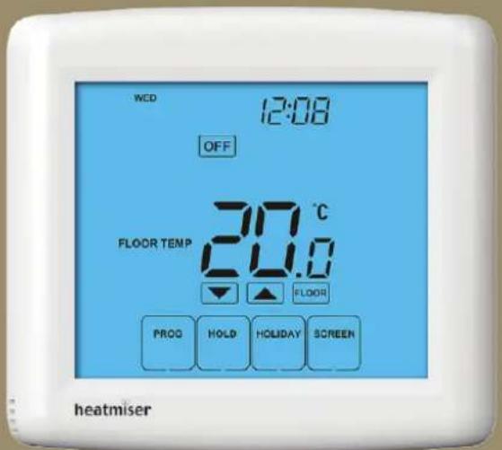
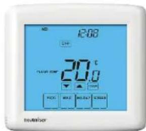
MED 12:08 OFF FLOOR TEMP 21.0°C FLOOR PROG HOLD HOLIDAY SCREENheatmiser
Model: PRT-ETS / PRT-ENTS _1Mo
Model: PRT-ETS / PRT-ENTS
text_image
WED 12:08 OFF FLOOR TEMP 20.0 °C FLOOR PROD HOLD HOLIDAY SCREEN heatmiser
Table Of Contents
| Product Image | 1 |
| Table of Contents | 2 |
| What is a Programmable Room Thermostat? | 3-4 |
| Installation Procedure | 5-6 |
| LCD Display | 7-8 |
| Setting the Clock | 9 |
| Temperature Display | 10 |
| Comfort Levels Explained | 11-12 |
| Clean Screen | 13 |
| Locking the Keypad | 13 |
| Temperature Control | 14 |
| Temperature Hold | 15 |
| Holiday Programming | 16 |
| Frost Protection | 17 |
| Heating ON/OFF | 18 |
| Optional Features Explained | 19-21 |
| Adjusting the Optional Settings | 22 |
| Optional Settings - Features Table | 23 |
| Error Codes | 24 |
| Re-calibrating the Thermostat | 25 |
| Factory Reset | 26 |
| Wiring Diagrams | 27-30 |
? What is a Programmable Room Thermostat?
A programmable room thermostat is both a programmer and a room thermostat.
The programmer allows you to set "On" and "Off" periods to suit your own lifestyle. The room thermostat works by sensing the air temperature, switching on the heating when the air temperature falls below the thermostat setting, and switching it off once this set temperature has been reached.
So a programmable room thermostat lets you choose what times you want the heating to be on, and what temperature it should reach while it is on. It will allow you to select different temperatures in your home at different times of the day (and days of the week) to meet your particular needs and preferences.
Setting a room thermostat to a higher temperature will not make the room heat up any faster. How quickly the room heats up depends on the design & size of the heating system.
Similarly reducing the temperature setting does not affect how quickly the room cools down. Setting a programmable room thermostat to a lower temperature will result in the room being controlled at a lower temperature, and saves energy.
The way to set and use your programmable room thermostat is to find the lowest temperature settings that you are comfortable with at the different times you have chosen, and then leave it alone to do its job.
The best way to do this is to set the room thermostat to a low temperature – say 18^ C, and then turn it up by 1^ C each day until you are comfortable with the temperature. You won't have to adjust the thermostat further. Any adjustment above this setting will waste energy and cost you more money.
If your heating system is a boiler with radiators, there will usually be only one programmable room thermostat to control the whole house. But you can have different temperatures in individual rooms by installing thermostatic radiator valves (TRVs) on individual radiators.
If you don't have TRVs, you should choose a temperature that is reasonable for the whole house. If you do have TRVs, you can choose a slightly higher setting to make sure that even the coldest room is comfortable, then prevent any overheating in other rooms by adjusting the TRVs.
You are able to temporarily adjust the heating program by overriding or using the temperature hold feature. These features are explained further on pages 14 and 15 of this manual.
Programmable room thermostats need a free flow of air to sense the temperature, so they must not be covered by curtains or blocked by furniture. Nearby electric fires, televisions, wall or table lamps may also prevent the thermostat from working properly.

Installation Procedure

Do
Mount the thermostat at eye level.
Read the instructions fully so you get the best from our product.

Don't
Do not install near to a direct heat source as this will affect functionality.
Do not push hard on the LCD screen as this may cause irreparable damage.
This Touchscreen Series thermostat is designed to be flush mounted and requires a back box of 35mm (minimum depth) to be sunk into the wall prior to installation.
Step 1
Carefully separate the front half of the thermostat from the back plate by placing a small flat head terminal driver into the slots on the bottom face of the thermostat.
Step 2
Place the thermostat front somewhere safe.
Terminate the thermostat as shown in the diagrams on pages 27-30 of this booklet.
Step 3
Screw the thermostat back plate securely into the back box.
Step 4
Clip the front of the thermostat back onto the thermostat back plate.

natural_image
White electronic device with a screen and cable, labeled '1' in the corner (no visible text or symbols on the device body)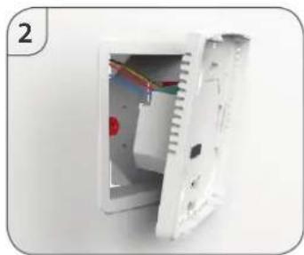
natural_image
White plastic electronic device with exposed internal components and wiring (no text or symbols visible)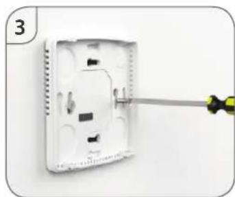
natural_image
Close-up of a white wall-mounted electrical socket with a screwdriver inserted, no visible text or symbols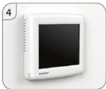
natural_image
White portable electronic device with a black screen and 'luofer' branding (no visible text or symbols on the device body)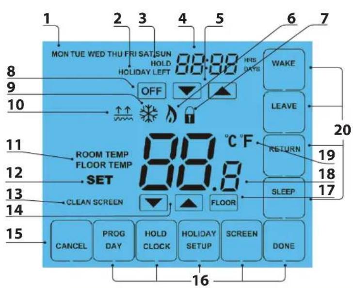
text_image
MON TUE WED THU FRI SAT SUN HOLD HOLIDAY LEFT OFF ROOM TEMP FLOOR TEMP SET CLEAN SCREEN CANCEL PROG DAY HOLD CLOCK HOLIDAY SETUP SCREEN DONE 16 17 18 19 20 WAKE LEAVE RETURN SLEEP HRS DAYS 88:00 °C F 88.8LCD
LCD Display
- Day Indicator - Displays the day of the week.
- Holiday Indicator - Displayed when the thermostat is in Holiday mode.
- Temperature Hold - Displayed when the thermostat is in Hold mode.
- Clock - Displays time in normal operation, time left in hold or days left in holiday mode.
- Up/Down Keys - Increase or decrease values shown on top digit group.
- Flame Icon - Displayed when the thermostat is calling for heat, the flame icon will flash when optimum start function is in operation.
- Keypad Lock Icon - Displayed when the keypad is locked.
- OFF Key - Single press to enable/disable frost protection or press and hold to turn off display.
- Frost Icon - Displayed when the thermostat is in frost protection mode.
- Floor Temp Achieved Icon - Displayed when the floor set point temperature is reached.
- Room/Floor Temp - Indicates the current temperature sensor mode.
- Set - Indicates when changes are being made to programs or temperature set points.
- Clean Screen - Freezes screen temporarily to enable cleaning.
- Up/Down Keys - Increase of decrease values shown on bottom digit group.
- Cancel Key - Used to exit setup/program operations.
- Setup/Programming Keys - Used to navigate setup options.
- View Floor Temperature Key - Used to change display to show floor temperature.
- Current Temp - Indicates the current sensor temperature.
- Units of Temperature - Degrees Celsius or Fahrenheit.
- Comfort Level Selection Keys - Used in comfort level setup (see page 11).

Setting the Clock
To set the clock, follow these steps.
- Press PROG
- Press CLOCK
CLOCK
• Use the Down key to set the hours .... - Use the Up key to set the minutes ____
• Use the Day key to set the day of the week ____ - Press DONE to confirm and exit ...... DONE

text_image
Day MOB 00:00 Hours Minutes Change Minutes Change Hours CNC-CL DAY DONE
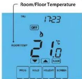
Temperature Display
The temperature display information is driven by two different inputs; the sensor measurement and the target temperature you have set.
text_image
Room/Floor Temperature THU 17:23 OFF ROOM TEMP 21.0 °C FLOOR PROG HOLD HOLIDAY SCREENThis is the current room/floor temperature.
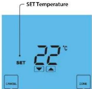
text_image
SET Temperature SET 22 °C CANCEL DONEThis is the temperature you are trying to achieve in your home.
When the thermostat is in air and floor sensing mode, the thermostat will display a FLOOR button.
Pressing this allows you to view the current floor temperature.
Pressing FLOOR again will return the thermostat to the room temperature display.

Comfort Levels Explained
Comfort levels allow you to set different temperatures throughout the day. For example, you may want the home warm in the morning when you are getting ready for work, cooler during the day when the house is unoccupied and then warmer in the evening when you are home relaxing.
The thermostat offers 2 programming options:
5/2 Day Programming - 4 levels for the weekdays and 4 different levels for the weekend.
7 Day Programming - 4 levels for each day.
See page 21 for details on how to switch between these modes.
Tip! If you don't want to use all of the comfort levels, just set the time to --.
Default comfort levels are pre-programmed but you can change them easily.
| Weekday Level | Time Temp | ||
| Wake | 08:00 | 21°C | |
| Leave | 09:30 | 16°C | |
| Return | 16:30 | 22°C | |
| Sleep | 23:00 | 17°C | |
| Weekend Level | Time Temp | ||
| Wake | 09:00 | 21°C | |
| Leave | 22:00 | 16°C | |
| Return | --,- | --°C | |
| Sleep | --,- | --°C |
- Press PROG ......
- Select WAKE
• Use the Up/Down keys to set the time for WAKE period ..... [▼] - Use the Up/Down keys to set the temperature ....
- Repeat these steps for the LEAVE, RETURN & SLEEP periods .....
- Press DAY to select the next day to program and repeat ....

text_image
SAT SUN 07:00 WAVE LEAVE RETURN SLEEP DONE CANCEL DAY THE 07:00 WAVE LEAVE RETURN SLEEP DONEIn 5/2 Day mode the thermostat will display "Sat Sun" prompting you to program the temperature levels for the weekend.
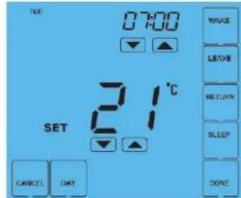
text_image
TUE 07:00 21°C SET WAVE LEAVE RETURN SLEEP DONE CANCEL DAYIn 7 Day mode, the thermostat will display Tue.
- When complete, press DONE to confirm settings and exit ....

Clean Screen
Pressing 📄 will disable all keys, providing you 15 seconds to wipe the screen clean before the keys are re-activated.

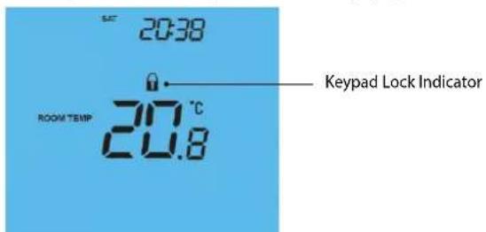
Locking the Keypad
The thermostat has a keypad lock facility.
• To activate the lock press the bottom right corner of the display and hold for 10 secs.
- When activated, you will see the Keypad Lock symbol.
• To cancel, press the bottom right corner of the display again for 10 secs.
text_image
20:38 ROOM TEMP 20.8 °C Keypad Lock Indicator
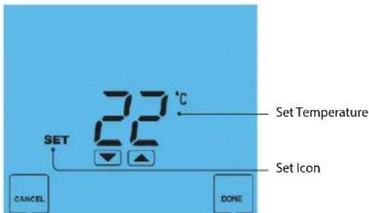
Temperature Control
The ▼▲ keys under the temperature display allow you to adjust the set temperature.
When you press either of these keys, you will see the temperature and the word SET appear on screen.
Select the desired temperature and press DONE to confirm and exit.
Note: This new temperature is maintained only until the next programmed comfort level. At this time, the thermostat will revert back to the programmed levels.
text_image
SET 22°C CANCEL DONE Set Icon Set Temperature
Temperature Hold
The temperature Hold function allows you to manually override the current operating program and set a different temperature for a desired period.
text_image
Hold Icon Hold Time HOLD 00:30 °C SET 22 °C Hold Temperature CANCEL DONETo cancel a Temperature Hold, follow the same steps but reduce the time to 00:00.

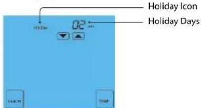
Holiday
The Holiday function reduces the set temperature in your home to the frost protection temperature setting (see page 19).
The thermostat will maintain this temperature for the duration of the holiday and will then automatically return to the program mode on your return.
- Press HOLIDAY
- Enter the desired duration in days ....
- Press DONE to confirm and exit ....
Note: A holiday period does not start until 00:00 the next day. For example, if you set a holiday period on Friday for 2 days, Saturday will be counted as the first day and the thermostat will revert back to the programmed schedule at 00:00 on Monday.
text_image
Holiday Icon Holiday Days 02 01 C:\WINDOWS\THM\STOPTo cancel a Holiday setting, reduce the Holiday time to 00 days.

Frost Mode
Pressing the OFF key once will place the thermostat in frost protect mode.
In this mode, the thermostat will display the frost icon and will only turn the heating on should the room temperature drop below the set frost temperature (see page 19).
Should the heating be turned on whilst in frost mode, the flame symbol will be displayed.
To cancel the frost protect mode, press the OFF key once.

text_image
MON 18:03 OFF ROOM TEMP 20.8°C PROG HOLD HOLIDAY SCREEN Frost Protection Mode Enabled
Heating On/Off
The heating is indicated ON when the flame icon is displayed.
When the flame icon is absent, there is no requirement for heating to achieve the set temperature but the thermostat remains active.
To turn the thermostat OFF completely, press and hold the OFF key ....OFF
The display and heating output will be turned off completely.*
To turn the thermostat back ON, press the ON key once ...... ON
Thermostat completely OFF
natural_image
White rectangular electronic device with a black screen and a small logo on the front panel (no readable text or symbols)Thermostat powered ON
text_image
12:00 OFF 20.0 FLUOR TIME 20.0 STOP PICK MAKE MAKEOUT START Revitaber*See Feature 3 on page 19

Optional Features Explained
THE FOLLOWING SETTINGS ARE OPTIONAL AND IN MOST CASES NEED NOT BE ADJUSTED
Feature 01 - Temperature Format: This function allows you to select between ^ or ^ .
Feature 02 - Switching Differential: This function allows you to increase the switching differential of the thermostat. The default is 1°C which means the thermostat will switch the heating on 1°C below the set temperature and will turn it off when the set temperature is achieved. With a 2°C differential, the heating will switch on 2°C below the set temperature and will switch off when the set temperature is achieved.
Feature 03 - Frost Protect: You can set whether the thermostat will maintain the frost temperature when the thermostat display is turned off. As a default, this is enabled.
Feature 04 – Frost Protect Temperature: This is the temperature maintained when the thermostat is in frost mode. The range is 07-17°C. The default is 12°C and is suitable for most applications.
Feature 05 – Output Delay: To prevent rapid switching, an output delay can be entered. This can be set from 00 -15 minutes. The default is 00 which means there is no delay.
Feature 06 – Communication Address: This setting is used when you have connected your thermostat to a network system. Each thermostat on the network must have a unique communication address. This can be set from 01-32.
Feature 07 – Temperature Up/Down Limit: This function allows you to limit the use of the up and down keys. This limit is also applicable when the thermostat is locked and so allows you to give others limited control over the heating system.
Feature 08 – Sensor Selection: This thermostat offers 5 sensor modes.
00 = Built in air sensor. In this mode, the thermostat will maintain the set temperature by monitoring the built in air sensor. Note: Built in air sensor only MUST NOT be used to control electric under-floor heating. Floor sensor only or built in air & floor sensor together must be used.
01 = Remote air sensor. In this mode, the thermostat will maintain the set temperature by monitoring the remote air sensor.
02 = Floor sensor. In this mode, the thermostat will maintain the set temperature by monitoring the remote floor temperature.
03 = Floor sensor and built in air sensor. In this mode, the thermostat will maintain the set temperature by monitoring the built in air sensor and will also ensure the floor surface doesn't overheat by monitoring the remote floor sensor.
04 = Floor sensor and remote air sensor. In this mode, the thermostat will maintain the set temperature by monitoring the remote air sensor and will also ensure the floor surface doesn't overheat by monitoring the remote floor sensor.
Feature 09 – Floor Limit Temperature: This function allows you to set a maximum floor temperature in order to protect the floor surface from overheating. This function works for Sensor Modes 03 & 04 (see above). The default setting is 28°C.

Optional Features Continued
Feature 10 – Optimum Start: Optimum start will delay the start up of the heating system to the latest possible moment to avoid unnecessary heating and ensure the building is warm at the programmed time. The thermostat uses the rate of change information to calculate how long the heating needs to raise the building temperature 1^ C (with a rate of change of 20, the thermostat has calculated the heating needs 20 minutes to raise the building temperature 1^ C) and starts the heating accordingly.
Feature 11 – Rate Of Change: This is the number of minutes the thermostat has calculated it takes to raise your building temperature 1^ C. The thermostat will continue to monitor and learn the heat up time of your home to optimise heating efficiency.
Feature 12 - Programming Mode: The thermostat offers 2 programming methods. Weekday/Weekend allows you to program 4 comfort levels for the weekdays and 4 different comfort levels for the weekend. In 7 Day program mode, each day has 4 comfort levels that can be programmed independently.

Adjusting the Optional Settings
To adjust the optional settings, follow these steps.
- Press PROG ......
- Press SETUP
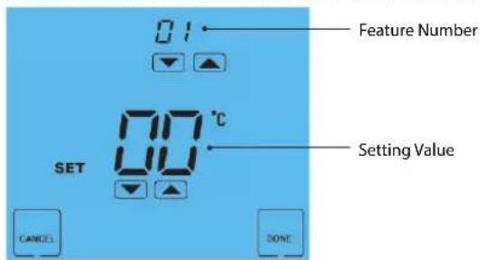
text_image
01 Feature Number 00 °C SET Setting Value CANCEL DONEOptional Settings - Feature Table
| FEATURE | DESCRIPTION | SETTING |
| 01 | Temperature Format | 00 = ^, 01 = ^ (°C = Default) |
| 02 | Switching Differential | 0.5^ - 3.0^ (1^ = Default) |
| 03 | Frost Protect | 00 = Disabled, 01 = Enabled (01 = Default) |
| 04 | Frost Protection Temperature | 07^ - 17^ (12^ = Default) |
| 05 | Output Delay | Enter Value: 00 - 15 Minutes (00 = Default) |
| 06 | Communications ID No. | Enter number 01-32 |
| 07 | Up/Down Temperature Limit | 00^ - 10^ (00 = Default) |
| 08 | Sensor Selection | 00 = Built in Air Sensor 01 = Remote Air Sensor 02 = Floor Sensor 03 = Floor Sensor and Built In Air Sensor 04 = Floor Sensor and Remote Air Sensor |
| 09 | Floor Temperature Limit | 20-45^ (28^ = Default) |
| 10 | Optimum Start | 00 = Disabled (Default) 01 = 01hr, 02 = 02hr, 03 = 03hr |
| 11 | Rate of Change | For Information Only |
| 12 | Program Mode | 00 = Weekday/Weekend (Default) 01 = 7 Day Programming |

Error Codes
E0 = The internal sensor has developed a fault.
You should contact your thermostat retailer for assistance.
E1 = The remote floor probe has not been connected, has been wired incorrectly or the probe is faulty.
E2 = The remote air probe has not been connected, has been wired incorrectly or the probe is faulty.
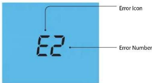
text_image
Error Icon E2 Error Number
Re-calibrating the Thermostat
If you need to re-calibrate the thermostat, follow these steps.
text_image
26.0 °C SET CANCEL DONE Calibration Temperature Setting Set Icon
Factory Reset
The thermostat has a reset function to restore all settings to their factory defaults.
To perform a factory reset, follow these steps.
- Press & hold the OFF key to turn the thermostat display OFF ....OFF
- Press and hold the bottom left corner of the LCD for 10 seconds.
• All of the screen icons will appear for 2 seconds and then disappear. - Press the ON key once to turn the thermostat display back ON ____ ON
All icons displayed simultaneously.

text_image
88:38 OFF ▼ +2 ▲ 89.8 °C ROOM TEMPLE FLUORE TEMPLE 温度 T CLEAR NUMBER ▼ ▲ FLOOR CANCEL PICO BATT POLD CLOSE HOLDUP SETUP SWITCH DONEFactory reset is complete.

text_image
OK
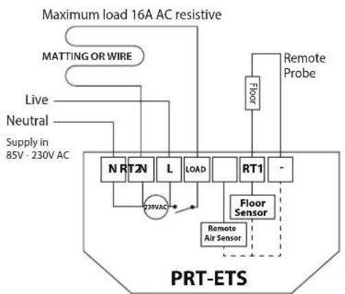
Wiring Diagram - PRT-ETS
With Remote Floor and Air Sensors for Use in Wet Areas
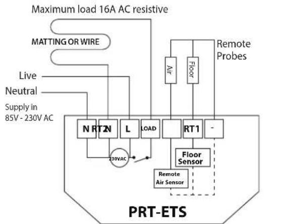
flowchart
graph TD
    A["Maximum load 16A AC resistive"] --> B["MATTING OR WIRE"]
    B --> C["Live"]
    B --> D["Neutral"]
    C --> E["Supply in 85V - 230V AC"]
    D --> E
    E --> F["N RT2N"]
    E --> G["L"]
    E --> H["LOAD"]
    E --> I["RT1"]
    E --> J["-"]
    F --> K["230VAC"]
    G --> K
    H --> K
    I --> K
    J --> K
    K --> L["Floor Sensor"]
    L --> M["Remote Air Sensor"]
    L --> N["Remote Probes"]
The mains supply must be properly protected and fused.

Wiring Diagram - PRT-ETS
With Remote Floor Probe Used for Use in Dry Areas or For Direct Floor Control
flowchart
graph TD
    A["Maximum load 16A AC resistive"] --> B["MATTING OR WIRE"]
    B --> C["Live"]
    B --> D["Neutral"]
    C --> E["Supply in 85V - 230V AC"]
    D --> E
    E --> F["NRT2N"]
    E --> G["L"]
    E --> H["LOAD"]
    E --> I["RT1"]
    I --> J["-"]
    J --> K["Floor Sensor"]
    K --> L["Remote Air Sensor"]
    L --> M["230VAC"]
    M --> N["Ground"]
    J --> O["Remote Probe"]
    O --> P["Floor"]
    P --> Q["Ground"]
The mains supply must be properly protected and fused.

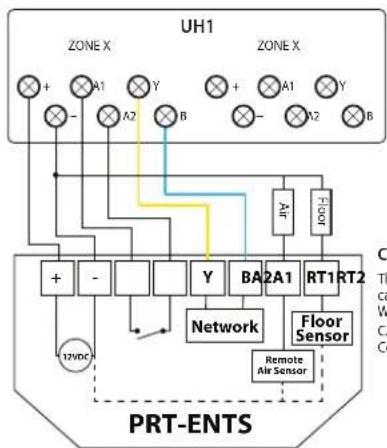
Wiring Diagram - PRT-ENTS
Optional Remote Air Sensor Connection For Use In Wet Areas
flowchart
graph TD
    subgraph UH1
        A1["Zone X"] --> B1["+"]
        A2["Zone X"] --> B2["+"]
        A3["Zone X"] --> B3["+"]
        A4["Zone X"] --> B4["+"]
        A5["Zone X"] --> B5["+"]
        A6["Zone X"] --> B6["+"]
    end
    subgraph PRT-ENTS
        C1["Network"] --> D1["12VDC"]
        D1 --> E1["+"]
        D1 --> E2["-"]
        E1 --> F1["Square"]
        E2 --> F2["Square"]
        F1 --> G1["Square"]
        F2 --> G2["Square"]
        G1 --> H1["Square"]
        G2 --> H2["Square"]
        H1 --> I1["Square"]
        H2 --> I2["Square"]
        I1 --> J1["Square"]
        I2 --> J2["Square"]
        J1 --> K1["Square"]
        J2 --> K2["Square"]
        K1 --> L1["Square"]
        K2 --> L2["Square"]
        L1 --> M1["Square"]
        L2 --> M2["Square"]
        M1 --> N1["Square"]
        M2 --> N2["Square"]
        N1 --> O1["Square"]
        N2 --> O2["Square"]
        O1 --> P1["Square"]
        O2 --> P2["Square"]
        P1 --> Q1["Square"]
        P2 --> Q2["Square"]
        Q1 --> R1["Square"]
        Q2 --> R2["Square"]
        R1 --> S1["Square"]
        R2 --> S2["Square"]
        S1 --> T1["Square"]
        S2 --> T2["Square"]
        T1 --> U1["Square"]
        T2 --> U2["Square"]
        U1 --> V1["Square"]
        U2 --> V2["Square"]
        V1 --> W1["Square"]
        V2 --> W2["Square"]
        W1 --> X1["Square"]
        W2 --> X2["Square"]
        X1 --> Y1["Square"]
        X2 --> Y2["Square"]
        Y1 --> Z1["Square"]
        Y2 --> Z2["Square"]
        Z1 --> AA1["Square"]
        Z2 --> AA2["Square"]
        AA1 --> AB1["Square"]
        AA2 --> AB2["Square"]
        AB1 --> AC1["Square"]
        AB2 --> AC2["Square"]
        AC1 --> AD1["Square"]
        AD1 --> AE1["Square"]
        AD2 --> AE2["Square"]
        AE1 --> AF1["Square"]
        AE2 --> AF2["Square"]
        AF1 --> AG1["Square"]
        AF2 --> AG2["Square"]
Connecting PRT-ENTS to the UH1
The UH1 is an 8 zone wiring centre that can be expanded to control up to 32 zones. When connecting PRT-ENTS to the UH1 use CAT5-FTP or BELDEN 9538. Connect the screen to Earth at the UH1.
PRT-ENTS for use in wet area where floor temperature control or limiting is required.

Wiring Diagram - PRT-ENTS to PRC
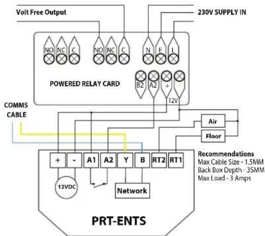
flowchart
graph TD
    A["Volt Free Output"] --> B["POWERED RELAY CARD"]
    B --> C["230V SUPPLY IN"]
    C --> D["Air"]
    D --> E["Floor"]
    E --> F["PRT-ENTS"]
    F --> G["Network"]
    G --> H["12VDC"]
    H --> I["A1"]
    H --> J["A2"]
    H --> K["Y"]
    H --> L["B"]
    H --> M["RT2"]
    H --> N["RT1"]
    B --> O["COMMS CABLE"]
    O --> F
    style A fill:#f9f,stroke:#333
    style F fill:#ccf,stroke:#333
    style G fill:#cfc,stroke:#333
    style H fill:#fcc,stroke:#333
    style I fill:#ffc,stroke:#333
    style J fill:#ffc,stroke:#333
    style K fill:#ffc,stroke:#333
    style L fill:#ffc,stroke:#333
    style M fill:#ffc,stroke:#333
    style N fill:#ffc,stroke:#333
For 230V switched live output, link mains L to C

text_image
heatmiser™ PRODUCT INSTALLATION GUIDEHeating Professionals:
Request a copy of our product installation guide containing detailed technical specifications for our complete product range: www.heatmiser.com/guide
Want More Information?
Call our support team on: +44 (0)1254 669090
Or view technical specifications directly on our website: www.heatmiser.com

natural_image
Abstract orange line drawing on white background (no text or symbols)
natural_image
Orange question mark icon inside a rounded square (no text or symbols)PDF FAQ
31 TouchScreen Series

Follow us on: twitter
Twitter: heatmiseruk

Find us on: facebook®
Facebook: facebook.com/thermostats