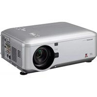
XG-PH80WN - Video projector SHARP - Free user manual and instructions
Find the device manual for free XG-PH80WN SHARP in PDF.


| Product Type | DLP Video Projector |
| Brand | Sharp |
| Model | XG-PH80WN |
| Display Technology | Single 0.7" DLP® Chip |
| Brightness | 8000 ANSI Lumens |
| Native Resolution | XGA (1024 x 768) |
| Contrast Ratio | 2500:1 (full on/off) |
| Lamp Type | NSHA (330W) x 2 |
| Lamp Life | Up to 2000 hours (Normal Mode) |
| Dimensions (W x H x D) | 505 x 195 x 385 mm (19.9" x 7.7" x 15.2") |
| Weight | Approx. 10.9 kg (24.0 lbs) |
| Power Supply | AC 100-240V, 50/60Hz |
| Power Consumption | 880W (max) |
| Lens Shift | Motorized: Vertical ±50%, Horizontal ±10% |
| Key Features | Multiple input options (HDMI, DVI, VGA, S-Video, Composite), Edge Blending, Picture-in-Picture, Network control (RJ-45) |
| Maintenance & Cleaning | Regular filter cleaning required; lamp replacement accessible via top cover |
| Safety | Overheat protection; auto power-off; Kensington lock slot |
| Spare Parts & Repairability | Replacement lamps and filters available; serviceable by qualified technicians |
| General Information | Designed for large venue installations; supports 24/7 operation |
Frequently Asked Questions - XG-PH80WN SHARP
User questions about XG-PH80WN SHARP
0 question about this device. Answer the ones you know or ask your own.
Ask a new question about this device
Download the instructions for your Video projector in PDF format for free! Find your manual XG-PH80WN - SHARP and take your electronic device back in hand. On this page are published all the documents necessary for the use of your device. XG-PH80WN by SHARP.
USER MANUAL XG-PH80WN SHARP
natural_image
Line drawing of a projector with visible lens and ventilation slots (no text or symbols)
PJLink™
IMPORTANT
- For your assistance in reporting the loss or theft of your Projector, please record the Model and Serial Number located on the bottom of the projector and retain this information.
- Before recycling the packaging, please ensure that you have checked the contents of the carton thoroughly against the list of “Supplied accessories” on page 11.
Model No.:
Serial No.:
SPECIAL NOTE FOR USERS IN THE U.K.
The mains lead of this product is fitted with a non-rewireable (moulded) plug incorporating a 10A fuse. Should the fuse need to be replaced, a BSI or ASTA approved BS 1362 fuse marked 🏠 or 📞 and of the same rating as above, which is also indicated on the pin face of the plug, must be used.
Always refi t the fuse cover after replacing the fuse. Never use the plug without the fuse cover fi tted.
In the unlikely event of the socket outlet in your home not being compatible with the plug supplied, cut off the mains plug and fit an appropriate type.
DANGER:
The fuse from the cut-off plug should be removed and the cut-off plug destroyed immediately and disposed of in a safe manner.
Under no circumstances should the cut-off plug be inserted elsewhere into a 13A socket outlet, as a serious electric shock may occur.
To fit an appropriate plug to the mains lead, follow the instructions below:
WARNING:
THIS APPARATUS MUST BE EARTHED.
IMPORTANT:
The wires in this mains lead are coloured in accordance with the following code:
| Green-and-yellow | : | Earth | |
| Blue | : | Neutral | |
| Brown | : | Live |
As the colours of the wires in the mains lead of this apparatus may not correspond with the coloured markings identifying the terminals in your plug proceed as follows:
- The wire which is coloured green-and-yellow must be connected to the terminal in the plug which is marked by the letter E or by the safety earth symbol 12 or coloured green or green-and-yellow.
- The wire which is coloured blue must be connected to the terminal which is marked with the letter N or coloured black.
- The wire which is coloured brown must be connected to the terminal which is marked with the letter L or coloured red.
IF YOU HAVE ANY DOUBT, CONSULT A QUALIFIED ELECTRICIAN.
Authorized representative responsible for the European Union Community Market
SHARP ELECTRONICS (Europe) GmbH
The supplied CD-ROM contains operation instructions in English, German, French, Spanish, Italian, Dutch, Swedish, Portuguese, Chinese, Korean and Arabic. Carefully read through the operation instructions before operating the projector.
Before using the projector, please read this operation manual carefully.
Introduction
ENGLISH
There are two important reasons for prompt warranty registration of your new SHARP Projec tor, using the REGISTRATION CARD packed with the projector.
1. WARRANTY
This is to assure that you immediately receive the full benefit of the parts, service and labor warranty applicable to your purchase.
2. CONSUMER PRODUCT SAFETY ACT
To ensure that you will promptly receive any safety notification of inspection, modification, or recall that SHARP may be required to give under the 1972 Consumer Product Safety Act, PLEASE READ CAREFULLY THE IMPORTANT "LIMITED WARRANTY" CLAUSE.
U.S.A. ONLY
WARNING:
High brightness light source. Do not stare into the beam of light, or view directly. Be especially careful that children do not stare directly into the beam of light.

WARNING: To reduce the risk of fire or electric shock, do not expose this product to rain or moisture.
See bottom of projector.

CAUTION: TO REDUCE THE RISK OF ELECTRIC SHOCK, DO NOT REMOVE COVER. NO USER-SERVICEABLE PARTS EXCEPT LAMP UNIT. REFER SERVICING TO QUALIFIED SERVICE PERSONNEL.


The lightning flash with arrowhead symbol, within an equilateral triangle, is intended to alert the user to the presence of uninsulated “dangerous voltage” within the product's enclosure that may be of sufficient magnitude to constitute a risk or electric shock to persons.
The exclamation point within a triangle is intended to alert the user to the presence of important operating and maintenance (servicing) instructions in the literature accompanying the product.
WARNING:
This is a Class A product. In a domestic environment this product may cause radio interference in which case the user may be required to take adequate measures.
WARNING:
FCC Regulations state that any unauthorized changes or modifications to this equipment not expressly approved by the manufacturer could void the user's authority to operate this equipment.
U.S.A. ONLY
The enclosed computer cable must be used with the device. The cable is provided to ensure that the device complies with FCC Class A verification.
U.S.A. ONLY
INFORMATION
This equipment has been tested and found to comply with the limits for a Class A digital device, pursuant to Part 15 of the FCC Rules. These limits are designed to provide reasonable protection against harmful interference when the equipment is operated in a commercial environment. This equipment generates, uses, and can radiate radio frequency energy and, if not installed and used in accordance with the operation manual, may cause harmful interference to radio communications. Operation of this equipment in a residential area is likely to cause harmful interference, in which case the user will be required to correct the interference at his own expense. U.S.A. ONLY
U.S.A. ONLY
PRODUCT DISPOSAL
This product utilizes lamp containing a small amount of mercury. Disposal of these materials may be regulated due to environmental considerations. For disposal or recycling information, please contact your local authorities, the Electronics Industries Alliance: www.eiae.org, the lamp recycling organization www.lamprecycle.org, or Sharp at 1-800-BE-SHARP.
U.S.A. ONLY
Caution Concerning Lamp Replacement
This projector utilizes a pressurized mercury lamp. A loud sound may indicate lamp failure. Lamp failure can be attributed to numerous sources such as: excessive shock, improper cooling, surface scratches or deterioration of the lamp due to a lapse of usage time.
The period of time up to failure largely varies depending on the individual lamp and/or the condition and the frequency of use. It is important to note that failure can often result in the bulb cracking.
■ When the lamp replacement indicator and on-screen display icon are illuminated, it is recommended that the lamp be replaced with a new one immediately, even if the lamp appears to be operating normally.
■ Should the lamp break, there is also a possibility that glass particles may spread inside of the projector. In such a case, it is recommended you contact your nearest Sharp Authorized Projector Dealer or Service Center to assure safe operation.
■ Should the lamp break, the glass particles may spread inside the lamp cage or gas contained in the lamp may be vented into the room from the exhaust vent. Because the gas in this lamp includes mercury, ventilate the room well if the lamp breaks and avoid all exposure to the released gas. In case of exposure to the gas, consult a doctor as soon as possible.

Caution
- Do not remove the lamp unit from the projector right after use. The lamp will be very hot and may cause burns or injury.
- Wait at least one hour after the power cord is disconnected to allow the surface of the lamp unit to fully cool before removing the lamp unit.
- Do not touch the glass surface of the lamp unit or the inside of the projector.
- Do not loosen other screws except for the lamp unit cover and lamp unit.
- Make sure to reset the lamp timer only when replacing the lamp. If you reset the lamp timer and continue to use the same lamp, this may cause the lamp to become damaged or explode.
■ Carefully change the lamp by following the instructions described on pages 66 to 68. * If you wish, you may have the lamp replaced at your nearest Sharp Authorized Projector Dealer or Service Center.
* If the new lamp does not light after replacement, take your projector to the nearest Sharp Authorized Projector Dealer or Service Center for repair.
How to Read this Operation Manual
The specifications are slightly different, depending on the model. However, you can connect and operate all models in the same manner.
- In this operation manual, the illustration and the screen display are simplified for explanation, and may differ slightly from the actual display.

Info ......Indicates safeguards for using the projector.

Note ...... Indicates additional information for setting up and operating the projector.
For Future Reference
Maintenance

P. 61
Troubleshooting

PP. 73 to 75
Index

P. 79
Contents
Preparing
Introduction
How to Read this Operation Manual .....3
Contents......4
IMPORTANT SAFEGUARDS ......6
How to Access the PDF Operation Manuals....10
Accessories 11
Part Names and Functions 13
Top View 13
Front View 13
Side View (Terminals) 14
Inserting the Batteries 16
Usable Range 16
Easy Start
Easy Start 17
Setup and Projection 17
Setup
Setting Up the Projector 19
Video Setup.... 19
Setting Up the Projector 19
Standard Setup (Front Projection) 19
Projection (PRJ) Mode 20
Ceiling-Mount Setup 20
Connections
Connecting the Projector to Other Equipment 21
Controlling the Projector by a Computer ....24
Attaching the Optional Lens 26
Connecting the Power Cord 27
Using
Basic Operation
Turning the Projector On/Off 28
Turning the Projector On 28
Turning the Power Off (Putting the Projector into Standby Mode) 28
Image Projection 29
Shifting the Lens 29
Using the Adjustment Feet.... 30
Adjusting the Focus 31
Adjusting the Projected Image Size ...... 31
Correcting Trapezoidal Distortion 32
Switching the Input Mode 33
Adjusting the Volume 33
Displaying the Black Screen and Turning Off the Sound Temporarily ..... 33
Resize Mode 34
Useful Features
Operating with the Remote Control.....36
Auto Sync (Auto Sync Adjustment) ...... 36
Freezing a Moving Image 36
Using the Remote Control to Operate the Computer 37
Menu Items 38
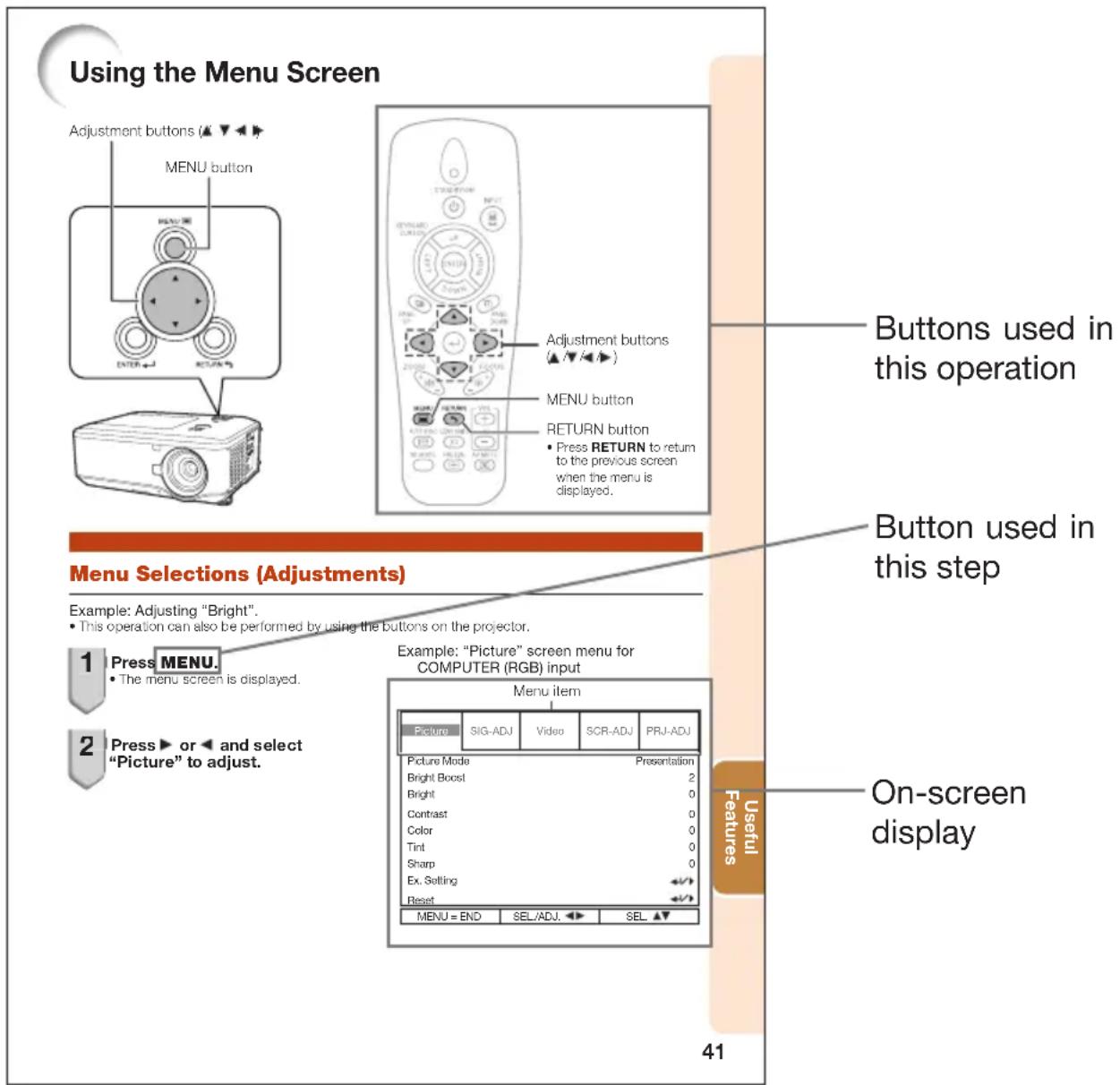
Using the Menu Screen 41
Menu Selections (Adjustments) .....41
Picture Adjustment ("Picture" Menu) ....43
Selecting the Picture Mode 43
Adjusting the Image 44
Using the Ex. Setting 44
Signal Type Setting 44
Adjusting the Color Temperature 44
Adjusting the Red/Blue 44
Adjusting the Colors 45
Selecting the Film Mode 45
Reducing Image Noise (DNR) 45
Setting the Dynamic Black 45
Signal Adjustment ("SIG-ADJ" Menu) ..46
Adjusting the Computer Image 46
Setting the Resolution 46
Auto Sync (Auto Sync Adjustment) ...... 46
Video Adjustment ("Video" Menu) .....47
Setting the Overscan 47
Setting the Video System 47
Setting the Video Setup 48
Closed Caption 48
Adjusting the Projected Image ("SCR - ADJ" Menu) 49
Selecting the On-screen Display Language ... 49
Selecting the Background Image 49
Reversing/Inverting Projected Images ..... 49
Setting the Resize Mode 49
Keystone Correction 50
Image Resizing 50
Selecting the Wall Color 50
Using the Ex. Setting 50
Security Lock Function 51
Keypad Lock Function 51
Image Capture.... 51
Adjusting the Projector Function
("PRJ - ADJ" Menu) 52
Detecting the Input Signals Automatically .. 52
Auto Power Off Function 52
Auto Restart Function 52
Eco+Quiet 52
Setting the Lamp Mode 53
Setting the Audio 53
Using the Ex. Setting 53
Fan Mode Setting 53
STANDBY Mode 53
STANDBY Audio Out 53
Filter Message 54
3D MODE 54
Setting the LAN/RS232C 54
Setting the Network 54
Returning to the Default Settings ..... 55
Information 55
Viewing Stereoscopic 3D Images .....56
Precautions on Viewing Stereoscopic
3D Images 56
Information on the 3D Projection Function .. 58
Using 3D Viewing Mode 59
Appendix....60
Reference
Appendix
Maintenance....61
Cleaning and Replacing the
Dust Filters 62
Cleaning the Dust Filters 62
Replacing the Dust Filters 62
Maintenance Indicators 64
Regarding the Lamp 66
Lamp 66
Caution Concerning the Lamp 66
Replacing the Lamp 66
Removing and Installing the
Lamp Unit 67
Resetting the Lamp Timer 68
Replacing the Color Wheel 69
Compatibility Chart 71
Troubleshooting......73
For SHARP Assistance 76
Specifications 77
Dimensions....78
Index....79
IMPORTANT SAFEGUARDS
CAUTION: Please read all of these instructions before you operate this product and save these instructions for later use.
Electrical energy can perform many useful functions. This product has been engineered and manufactured to assure your personal safety. BUT IMPROPER USE CAN RESULT IN POTENTIAL ELECTRICAL SHOCK OR FIRE HAZARDS. In order not to defeat the safeguards incorporated in this product, observe the following basic rules for its installation, use and servicing.
1. Read Instructions
All the safety and operating instructions should be read before the product is operated.
2. Retain Instructions
The safety and operating instructions should be retained for future reference.
3. Heed Warnings
All warnings on the product and in the operating instructions should be adhered to.
4. Follow Instructions
All operating and use instructions should be followed.
5. Cleaning
Unplug this product from the wall outlet before cleaning. Do not use liquid cleaners or aerosol cleaners. Use a damp cloth for cleaning.
6. Attachments
Do not use attachments not recommended by the product manufacturer as they may cause hazards.
7. Water and Moisture
Do not use this product near water—for example, near a bath tub, wash bowl, kitchen sink, or laundry tub; in a wet basement; or near a swimming pool; and the like.
8. Accessories
Do not place this product on an unstable cart, stand, tripod, bracket, or table. The product may fall, causing serious injury to a child or adult, and serious damage to the product. Use only with a cart, stand, tripod, bracket, or table recommended by the manufacturer, or sold with the product. Any mounting of the product should follow the manufacturer's instructions, and should use a mounting accessory recommended by the manufacturer.
9. Transportation
A product and cart combination should be moved with care. Quick stops, excessive force, and uneven surfaces may cause the product and cart combination to overturn.

natural_image
Symbolic icon of a person climbing a ladder inside a circle (no text or symbols)10. Ventilation
Slots and openings in the cabinet are provided for ventilation to ensure reliable operation of the product and to protect it from overheating, and these openings must not be blocked or covered. The openings should never be blocked by placing the product on a bed, sofa, rug, or other similar surface. This product should not be placed in a built-in installation such as a book case or rack unless proper ventilation is provided or the manufacturer's instructions have been adhered to.
11. Power Sources
This product should be operated only from the type of power source indicated on the marking label. If you are not sure of the type of power supply to your home, consult your product dealer or local power company. For products intended to operate from battery power, or other sources, refer to the operating instructions.
12. Grounding or Polarization
This product is provided with one of the following types of plugs. If the plug should fail to fit into the power outlet, please contact your electrician.
Do not defeat the safety purpose of the plug.
a. Two-wire type (mains) plug.
b. Three-wire grounding type (mains) plug with a grounding terminal.
This plug will only fit into a grounding type power outlet.
13. Power-Cord Protection
Power-supply cords should be routed so that they are not likely to be walked on or pinched by items placed upon or against them, paying particular attention to cords at plugs, convenience receptacles, and the point where they exit from the product.
14. Lightning
For added protection for this product during a lightning storm, or when it is left unattended and unused for long periods of time, unplug it from the wall outlet and disconnect the cable system. This will pre vent damage to the product due to lightning and power-line surges.
15. Overloading
Do not overload wall outlets, extension cords, or integral convenience receptacles as this can result in a risk of fire or electric shock.
16. Object and Liquid Entry
Never push objects of any kind into this product through openings as they may touch dangerous voltage points or short-out parts that could result in a fi re or electric shock. Never spill liquid of any kind on the product.
17. Servicing
Do not attempt to service this product yourself as opening or removing covers may expose you to dan ger ous voltage or other hazards. Refer all servicing to qualified service personnel.
18. Damage Requiring Service
Unplug this product from the wall outlet and refer servicing to qualified service personnel under the following conditions:
a. When the power-supply cord or plug is damaged.
b. If liquid has been spilled, or objects have fallen into the product.
c. If the product has been exposed to rain or water.
d. If the product does not operate normally by following the operating instructions. Adjust only those con trols that are covered by the operating instructions, as an improper adjustment of other controls may result in damage and will often require extensive work by a qualifi ed technician to restore the product to normal operation.
e. If the product has been dropped or damaged in any way.
f. When the product exhibits a distinct change in performance, this indicates a need for service.
19. Replacement Parts
When replacement parts are required, be sure the service technician has used replace ment parts specified by the manufacturer or have the same characteristics as the original part. Unauthorized substitutions may result in fire, electric shock, or other hazards.
20. Safety Check
Upon completion of any service or repairs to this product, ask the service technician to per form safety checks to determine that the product is in proper operating condition.
21. Wall or Ceiling Mounting
This product should be mounted to a wall or ceiling only as recommended by the manufacturer.
22. Heat
This product should be situated away from heat sources such as radiators, heat registers, stoves, or other products (including amplifiers) that produce heat.
- DLP® and the DLP logo are registered trademarks of Texas Instruments and DLP ® Link™ is a trademark of Texas Instruments.
- Microsoft® and Windows® are registered trademarks of Microsoft Corporation in the United States and/or other countries.
- PC/AT is a registered trademark of International Business Machines Corporation in the United States.
- Adobe® Reader® is a trademark of Adobe Systems Incorporated.
- Macintosh ^ is a registered trademark of Apple Computer, Inc. in the United States and/or other countries.
- PJLink is a registered trademark or an application trademark in Japan, the United States, Canada, E.U., China and/or other countries/regions.
- All other company or product names are trademarks or registered trademarks of their respective companies.
- Some IC chips in this product include confi dential and/or trade secret property belonging to Texas Instruments. Therefore you may not copy, modify, adapt, translate, distribute, reverse engineer, reverse assemble or discompile the contents thereof.
Observe the following safeguards when setting up your projector.
Caution concerning the lamp unit
■ Potential hazard of glass particles if lamp ruptures. In case of lamp rupture, contact your nearest Sharp Authorized Projector
Dealer or Service Center for replacement.
See "Regarding the Lamp" on page 66.
Caution concerning the setup of the projector
For minimal servicing and to maintain high image quality, SHARP recommends that this projector be installed in an area free from humidity, dust and cigarette smoke. When the projector is subjected to these environments, the vents and lens must be cleaned more often. As long as the projector is regularly cleaned, use in these environments will not reduce the overall operation life of the unit. Internal cleaning should only be performed by a Sharp Authorized Projector Dealer or Service Center.
Rest your eyes occasionally.
■ Continuously watching the screen for long hours will cause eye strain. Take regular breaks to rest your eyes.
Do not set up the projector in places exposed to direct sunlight or bright light.
■ Position the screen so that it is not in direct sunlight or room light. Light falling directly on the screen washes out the colors, making viewing diffi cult. Close the curtains and dim the lights when setting up the screen in a sunny or bright room.
Caution regarding placing of the projector
■ Place the projector on a level site within the adjustment range (10 degrees) of the adjustment foot.

natural_image
Two diagrams showing a hand holding a red X and a blue circle on a surface, with no text or symbols present.■ After the projector is purchased, a faint smell from the vent may appear when the power is first turned on. This is normal and is not a malfunction. It will disappear after the projector is used for a while.
When using the projector in high-altitude areas such as mountains (at altitudes of approximately 1,200 meters (4,000 feet) or more)
- When you use the projector in high-altitude areas with thin air, set “Fan Mode” to “High”. Neglecting this can affect the longevity of the optical system.
■ Use the projector at altitudes of 3,000 meters (10,000 feet) or less.
Warning about placing the projector in a high position
■ When placing the projector in a high position, make certain it is carefully secure to avoid personal injury caused by the projector falling down.
Do not subject the projector to hard impact and/or vibration.
■ Protect the lens so as not to hit or damage the surface of the lens.
Avoid locations with extremes of temperature.
■ The operating temperature of the projector is from 41^ F to 104^ F ( +5^ C to +40^ C).
■ The storage temperature of the projector is from 14°F to 140°F (-10°C to +60°C).
Do not block the exhaust and intake vents.
- Allow at least 11^13 / _16 inches (30 cm) of space between the exhaust vent and the nearest wall or obstruction.
■ Ensure that the intake vent and the exhaust vent are not obstructed.
If the cooling fan becomes obstructed, a protection circuit will automatically put the projector into Standby mode to prevent overheat damage. This does not indicate a malfunction. (See pages 64 and 65.)
Remove the projector power cord from the wall outlet and wait at least 10 minutes.
Place the projector where the intake and exhaust vents are not blocked, plug the power cord back in and turn on the projector. This will return the projector to the normal operating condition.
Caution regarding usage of the projector
If you are not to use the projector for a long time or before moving the projector, make certain you unplug the power cord from the wall outlet, and disconnect any other cables connected to it.
■ Do not carry the projector by holding the lens.
■ When storing the projector, ensure you attach the lens cap or dustproof cap to the projector.
■ Do not expose the projector to direct sunlight or place next to heat sources. Doing so may affect the cabinet color or cause deformation of the plastic cover.
Other connected equipment
- When connecting a computer or other audiovisual equipment to the projector, make the connections AFTER unplugging the power cord of the projector from the AC outlet and turning off the equipment to be connected.
■ Please read the operation manuals of the projector and the equipment to be connected for instructions on how to make the connections.
Using the projector in other countries
The power supply voltage and the shape of the plug may vary depending on the region or country you are using the projector in. When using the projector overseas, make sure you use an appropriate power cord for the country you are in.
Temperature monitor function
If the temperature inside the projector increases, due to blockage of the air vents, or the setting location, the lamp will turn off, the cooling fan will run and then the projector will enter Standby mode, and then the TEMP. (temperature warning)/STATUS indicator will blink. Refer to "Maintenance Indicators" on pages 64 and 65 for details.

Info
- The cooling fan regulates the internal temperature, and its performance is automatically controlled. The sound of the fan may change during projector operation due to changes in the fan speed. This does not indicate malfunction.
Optional lens installation
For installing an optional lens, refer to "Attaching the Optional Lens" on page 26 or the lens installation manual (supplied with the optional lens).
■ Remove the optional lens when carrying the projector. Carrying the projector with an optional lens attached can cause the projector to be damaged by vibration or other factors.
■ When carrying the projector with no lens attached, attach the dustproof cap to the projector.
Closed Caption uses Bitstream Vera fonts
Copyright (c) 2003 by Bitstream, Inc. All Rights Reserved. Bitstream Vera is a trademark of Bitstream, Inc. Permission is hereby granted, free of charge, to any person obtaining a copy of the fonts accompanying this license (“Fonts”) and associated documentation files (the “Font Software”), to reproduce and distribute the Font Software, including without limitation the rights to use, copy, merge, publish, distribute, and/or sell copies of the Font Software, and to permit persons to whom the Font Software is furnished to do so, subject to the following conditions:
The above copyright and trademark notices and this permission notice shall be included in all copies of one or more of the Font Software typefaces.
The Font Software may be modified, altered, or added to, and in particular the designs of glyphs or characters in the Fonts may be modified and additional glyphs or characters may be added to the Fonts, only if the fonts are renamed to names not containing either the words “Bitstream” or the word “Vera”.
This License becomes null and void to the extent applicable to Fonts or Font Software that has been modified and is distributed under the “Bitstream Vera” names.
The Font Software may be sold as part of a larger software package but no copy of one or more of the Font Software typefaces may be sold by itself.
THE FONT SOFTWARE IS PROVIDED "AS IS", WITHOUT WARRANTY OF ANY KIND, EXPRESS OR IMPLIED, INCLUDING BUT NOT LIMITED TO ANY WARRANTIES OF MERCHANTABILITY, FITNESS FOR A PARTICULAR PURPOSE AND NONINFRINGEMENT OF COPYRIGHT, PATENT, TRADEMARK, OR OTHER RIGHT. IN NO EVENT SHALL BITSTREAM OR THE GNOME FOUNDATION BE LIABLE FOR ANY CLAIM, DAMAGES OR OTHER LIABILITY, INCLUDING ANY GENERAL, SPECIAL, INDIRECT, INCIDENTAL, OR CONSEQUENTIAL DAMAGES, WHETHER IN AN ACTION OF CONTRACT, TORT OR OTHERWISE, ARISING FROM, OUT OF THE USE OR INABILITY TO USE THE FONT SOFTWARE OR FROM OTHER DEALINGS IN THE FONT SOFTWARE.
Except as contained in this notice, the names of Gnome, the Gnome Foundation, and Bitstream Inc., shall not be used in advertising or otherwise to promote the sale, use or other dealings in this Font Software without prior written authorization from the Gnome Foundation or Bitstream Inc., respectively. For further information, contact: fonts at gnome dot org.
How to Access the PDF Operation Manuals
PDF operation manuals in several languages are included in the CD-ROM. To utilize these manuals, you need to install Adobe ^ Reader ^ on your computer (Windows ^ or Macintosh ^ ).
Please download Adobe ^® Reader ^® from the Internet (http://www.adobe.com).
Accessing the PDF Manuals
For Windows®:
① Insert the CD-ROM in the CD-ROM drive.
② Double click the "My Computer" icon.
③ Double click the "CD-ROM" drive.
④ When you want to view the operation manual
1) Double click the "MANUALS" folder.
2) Double click the language (name of the folder) that you want to view.
3) Double click the pdf file to access the projector manuals.
When you want to view the SETUP MANUAL
1) Double click the "SETUP" folder.
2) Double click the language (name of the folder) that you want to view.
3) Double click the pdf file to access the SETUP MANUAL.
For Macintosh®:
① Insert the CD-ROM in the CD-ROM drive.
② Double click the "CD-ROM" icon.
③ When you want to view the operation manual
1) Double click the "MANUALS" folder.
2) Double click the language (name of the folder) that you want to view.
3) Double click the pdf file to access the projector manuals.
When you want to view the SETUP MANUAL
1) Double click the "SETUP" folder.
2) Double click the language (name of the folder) that you want to view.
3) Double click the pdf file to access the SETUP MANUAL.

Note
- If the desired pdf file cannot be opened by double clicking the mouse, start Adobe ^ Reader ^ first, then specify the desired file using the "File", "Open" menu.
SETUP MANUAL
Refer to the "SETUP MANUAL" contained on the supplied CD-ROM for details.
Setting up the Screen 2
Screen Size and Projection Distance 3
Connecting Pin Assignments 14
RS-232C Specifications and Commands 16
Setting up the Projector Network Environment 18
Controlling the Projector via LAN 24
Operating the Projector Using the PJLink ™ Protocol 27
Troubleshooting 28
Dimensions 31
Accessories
Supplied accessories
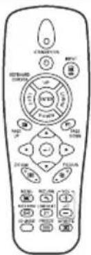
Remote control <9NK5041821400>

Two R-6 batteries ("AAA" size, UM/SUM-4, HP-7 or similar)

natural_image
Coiled electrical connector with two connectors (no text or symbols visible)RGB cable (6' (1.8 m)) <9NK3081405002>

Dustproof cap
<9NK3392038200>

Anti-theft screw <9NK3100132500>
Power cord ^* (1) (2) (3) (4)

For U.S., Canada, etc.
(6' (1.8 m))
<9NK3090204900>
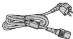
For Europe, except U.K.
(6' (1.8 m))
<9NK3090152701>

For U.K., Hong Kong and Singapore (6' (1.8 m))
<9NK3090152901>

For Australia, New Zealand and Oceania (6' (1.8 m)) <9NK3090152601>
* Which power cords are supplied along with your projector depends on the region. Use the power cord that corresponds to the wall outlet in your country.
- Operation manuals (manual pack (including this manual and CD-ROM))
For U.S., Canada and Taiwan: <9NK3534150200>
For Europe, Asia, Australia and New Zealand: <9NK3534160900>
For Korea: <9NK3534161000>

Note
- Codes in "< >" are Replacement parts codes.
- When the lens is attached, use the lens cap supplied with the lens.
- You can attach the dustproof cap to the projector only when no lens is attached. (Do not attach the dustproof cap when the lens is attached.)
Optional accessories
Lamp unit
■ Ceiling-mount unit
■ 3 RCA to mini D-sub 15 pin cable (10' (3.0 m))
■ Six-segment color wheel
AN-PH80LP
AN-XGCM80 (for U.S.A only)
AN-C3CP2
AN-PH80CW

Note
- Some of the optional accessories may not be available depending on the region. Please check with your nearest Sharp Authorized Projector Dealer or Service Center.
Accessories (Continued)
Optional accessories
| Lens Type | Projection Distance for 100" Screen Size | ||
| XG-PH80W-N XG-PH80X-N | |||
| Fixed wide lens (× 0.8) | AN-PH808EX 5'6" (1.7 m) 5'2" | (1.6 m) | |
| Wide-zoom lens (× 1.3 - 1.8) | AN-PH814EZ | 9'5" (2.9 m) - 12'8" (3.9 m) | 8'10" (2.7 m) - 11'11" (3.6 m) |
| Standard zoom lens (× 1.8 - 2.4) | AN-PH818EZ | 12'7" (3.8 m) - 16'7" (5.1 m) | 11'10" (3.6 m) - 15'8" (4.8 m) |
| Tele-zoom lens (× 2.2 - 4.4) | AN-PH823EZ | 15'8" (4.8 m) - 31'4" (9.5 m) | 14'10" (4.5 m) - 29'6" (9.0 m) |
| Tele-zoom lens (× 4.4 - 8.3) | AN-PH845EZ | 31'4" (9.5 m) - 58'8" (17.9 m) | 29'6" (9.0 m) - 55'4" (16.9 m) |
No lens is attached to XG-PH80W-N/XG-PH80X-N. The optional lenses from Sharp are also available for specialized application. Please see your nearest Sharp Authorized Projector Dealer for details on all the lenses. (Refer to the lens operation manual when using a lens.)
Throw Distance
XG-PH80W-N
The graph below is for 100-inch (254 cm) screen with 16:10 normal mode.
Screen
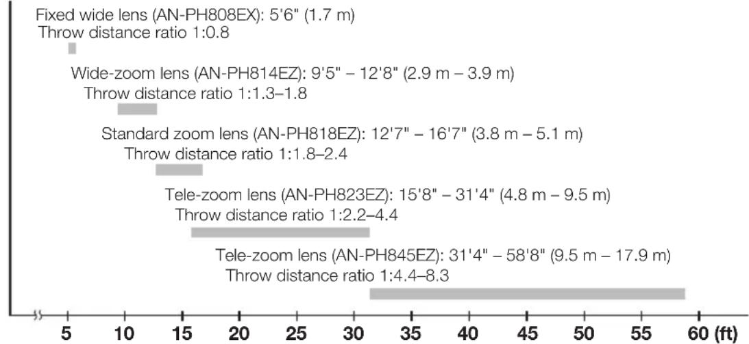
bar
| Lens Type | Throw distance ratio (ft) | Drop-off (m) | | :--- | :--- | :--- | | Fixed wide lens (AN-PH808EX) | 1.0 | 5'6" | | Wide-zoom lens (AN-PH814EZ) | 1.3-1.8 | 9'5" - 12'8" | | Standard zoom lens (AN-PH818EZ) | 1.8-2.4 | 12'7" - 16'7" | | Tele-zoom lens (AN-PH823EZ) | 2.2-4.4 | 15'8" - 31'4" | | Tele-zoom lens (AN-PH845EZ) | 4.4-8.3 | 31'4" - 58'8" | Throw distance ratio 1:0.8 | Throw distance ratio 1:1.3-1.8 Throw distance ratio 1:1.8-2.4 Throw distance ratio 1:2.2-4.4 Throw distance ratio 1:4.4-8.3 | Throw distance ratio 1:3.9-3.9 m Throw distance ratio 1:5.1 m Throw distance ratio 1:7.9 m Throw distance ratio 1:9.5 m Throw distance ratio 2:3.9 m Throw distance ratio 3:3.9 m Throw distance ratio 4:3.9 m Throw distance ratio 5:3.9 m Throw distance ratio 6:3.9 m Throw distance ratio 7:3.9 m Throw distance ratio 8:3.9 m Throw distance ratio 9:3.9 m Throw distance ratio 10:3.9 m Throw distance ratio 11:3.9 m Throw distance ratio 12:3.9 m Throw distance ratio 13:3.9 m Throw distance ratio 14:3.9 m Throw distance ratio 15:3.9 m Throw distance ratio 16:3.9 m Throw distance ratio 17:3.9 m Throw distance ratio 18:3.9 m Throw distance ratio 19:3.9 m Throw distance ratio 20:3.9 m Throw distance ratio 21:3.9 m Throw distance ratio 22:3.9 m Throw distance ratio 23:3.9 m Throw distance ratio 24:3.9 m Throw distance ratio 25:3.9 m Throw distance ratio 26:3.9 m Throw distance ratio 27:3.9 m Throw distance ratio 28:3.9 m Throw distance ratio 29:3.9 m Throw distance ratio 30:3.9 m Throw distance ratio 31:3.9 m Throw distance ratio 32:3.9 m Throw distance ratio 33:3.9 m Throw distance ratio 34:3.9 m Throw distance ratio 35:3.9 m Throw distance ratio 36:3.9 m Throw distance ratio 37:3.9 m Throw distance ratio 38:3.9 m Throw distance ratio 39:3.9 m Throw distance ratio 40:3.9 m Throw distance ratio 41:3.9 m Throw distance ratio 42:3.9 m Throw distance ratio 43:3.9 m Throw distance ratio 44:3.9 m Throw distance ratio 45:3.9 m Throw distance ratio 46:3.9 m Throw distance ratio 47:3.9 m Throw distance ratio 48:3.9 m Throw distance ratio 49:3.9 m Throw distance ratio 50:3.9 m Throw distance ratio 51:3.9 m Throw distance ratio 52:3.9 m Throw distance ratio 53:3.9 m Throw distance ratio 54:3.9 m Throw distance ratio 55:3.9 m Throw distance ratio 56:3.9 m Throw distance ratio 57:3.9 m Throw distance ratio 58:3.9 m Throw distance ratio 59:3.9 m Throw distance ratio 60:3.9 mXG-PH80X-N
The graph below is for 100-inch (254 cm) screen with 4:3 normal mode.
Screen

bar
| Lens Type | Range (ft) | Throw distance ratio | | :--- | :--- | :--- | | Fixed wide lens (AN-PH808EX): 5'2" (1.6 m) | 5-10 | 1:0.8 | | Wide-zoom lens (AN-PH814EZ): 8'10" - 11'11" (2.7 m - 3.6 m) | 10-15 | 1:1.3-1.8 | | Standard zoom lens (AN-PH818EZ): 11'10" - 15'8" (3.6 m - 4.8 m) | 15-20 | 1:1.8-2.4 | | Tele-zoom lens (AN-PH823EZ): 14'10" - 29'6" (4.5 m - 9.0 m) | 20-25 | 1:2.2-4.4 | | Tele-zoom lens (AN-PH845EZ): 29'6" - 55'4" (9.0 m - 16.9 m) | 25-30 | 1:4.4-8.3 | The chart displays a horizontal bar for each lens type, with the length of the bar labeled as 'm'. The values are in feet on the x-axis.Part Names and Functions
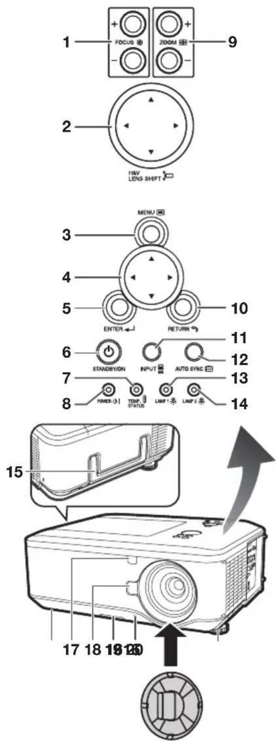
Numbers in ■ refer to the main pages in this operation manual where the topic is explained.
Attaching the lens cap/dustproof cap Snap on the lens cap/dustproof cap straight.
Removing the lens cap/dustproof cap Pull the lens cap/dustproof cap directly outward.
Top View
1 FOCUS buttons 31
For adjusting the focus.
2 H&V LENS SHIFT (▲/▼/◄/►) buttons 30
For shifting the lens horizontally and vertically.
3 MENU button41
For displaying adjustment and setting screens.
4 Adjustment buttons (▲/▼/◄/►) 41
For selecting menu items.
5 ENTER button 33
For setting items selected or adjusted on the menu.
6 STANDBY/ON button28
For turning the power on and putting the projector into Standby mode.
7 TEMP. (temperature warning)/STATUS indicator 64
8 POWER indicator 64
9 ZOOM buttons31
For adjusting the projected image size.
10 RETURN button41
For returning to the previous menu screen during menu operations.
11 INPUT button33
For switching Input mode.
12 AUTO SYNC buttc36
For automatically adjusting images when connected to a computer.
13 LAMP 1 indicato64
14 LAMP 2 indicato64
Front View
15 Carrying handle
For carrying the projector.
16 Adjustment foot30
17 Remote control sensor
18 LENS RELEASE button
19 Dust fi Ite 62
20 Anti-theft screw 27
16
26
[Non-Text]
Part Names and Functions (Continued)
Numbers in ■ refer to the main pages in this operation manual where the topic is explained.

Side View (Terminals)
1 COMPUTER/COMPONENT1 input terminals 21, 23 Terminal for computer RGB and component signals and audio input terminal.
2 LAN terminal 25 Terminal for controlling the projector using a computer via network.
3 USB terminal 37 Terminal connecting with the USB terminal on the computer for using the supplied remote control as the computer key board.
4 DVI-D input terminals 21, 22 Terminals for DVI digital RGB and digital component signals and audio input terminal.
5 MONITOR OUT terminals 23 • COMPUTER/COMPONENT output terminal for computer RGB and component signals. (Shared for COMPUTER/COMPONENT1 and 2, COMPONENT input) • AUDIO output terminal. (Shared for all inputs)
6 COMPUTER/COMPONENT2 input terminals 21, 22 BNC terminals for computer RGB and component signals and audio input term
7 RS-232C terminal 24 Terminal for controlling the projector using a computer.
8 TRIGGER terminal When the projector is turned on, a control signal (DC 12V) outputs from this terminal. If an electric screen or other compatible device is connected, it can be turned on when the projector is turned on.
9 Speaker 53 10 Intake vent 62 11 Dust filter 62 12 AC socket 27
Connect the supplied power cord.
13 MAIN POWER switch 26 Turn the projector On or Off.
14 Remote control senso16 15 Exhaust vent 62
16 Kensington Security Standard connector 17 COMPONENT input terminals 22 Terminals for component signals and audio input terminal.
18 VIDEO input terminals 23 Terminal for connecting video equipment and audio input terminal.
19 S-VIDEO input terminals 23 Terminal for connecting video equipment with an S-video terminal and audio input terminal.
Using the Kensington Lock
- This projector has a Kensington Security Standard connector for use with a Kensington MicroSaver Security System. Refer to the information that came with the system for instructions on how to use it to secure the projector.
Numbers in ■ refer to the main pages in this operation manual where the topic is explained.

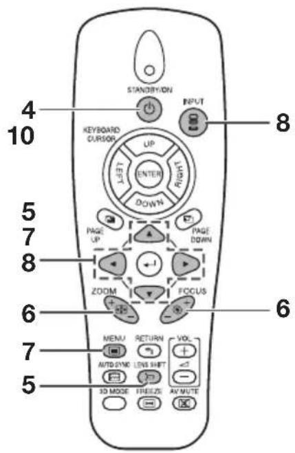
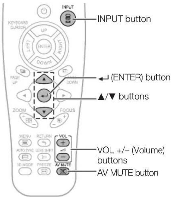
1 STANDBY/ON button28
For turning the power on and putting the projector into Standby mode.
2 KEYBOARD CURSOR (UP/DOWN/LEFT/RIGHT/ENTER) buttons 37
- For moving the computer cursor when with the USB connection (using a USB cable).
- Same as the [Enter] key on a computer keyboard, when with the USB connection (using a USB cable).
3 PAGE UP button 37
Same as the [Page Up] key on a computer keyboard, when with the USB connection (using a USB cable).
4 Adjustment buttons (▲/▼/◄/►) 30, 41
For selecting and adjusting menu items.
5 ZOOM buttons31
For adjusting the projected image size.
6 MENU button41
For displaying adjustment and setting screens.
7 AUTO SYNC butto36
For automatically adjusting images when connected to a computer.
8 LENS SHIFT button 30
For displaying the lens shift adjustment screen.
9 3D MODE button 59
For displaying the 3D MODE menu screen.
10 INPUT button 33
For switching Input mode.
11 PAGE DOWN button37
Same as the [Page Down] key on a computer keyboard, when with the USB connection (using a USB cable).
12 (ENTER) button 33
For setting items selected or adjusted on the menu.
13 FOCUS buttons 31
For adjusting the focus.
14 RETURN button41
For returning to the previous menu screen during menu operations.
15 VOL +/- (Volume) buttons 33
For adjusting the speaker sound level.
16 AV MUTE button 33
For temporarily displaying a black screen and turning off the sound.
17 FREEZE button36
For freezing images.
Part Names and Functions (Continued)
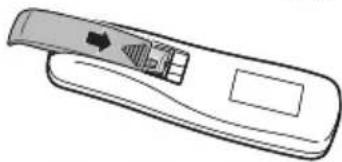
Inserting the Batteries
1 Remove the cover by sliding towards the direction of the arrow.

natural_image
Line drawing of a remote control device with a scroll wheel and indicator lights (no text or symbols)2 Insert the batteries.

- Insert the batteries making sure the polarities correctly match the and marks inside the battery compartment.
3 Replace the cover.
natural_image
Line drawing of a remote control device with a scroll wheel and indicator lights (no text or symbols)Incorrect use of the batteries may cause them to leak or explode. Please follow the precautions below

Caution
- Danger of explosion if battery is incorrectly replaced. Replace only with alkaline or manganese batteries.
- Insert the batteries making sure the polarities correctly match the and marks inside the battery compartment.
- Batteries of different types have different properties, therefore do not mix batteries of different types.
- Do not mix new and old batteries.
This may shorten the life of new batteries or may cause old batteries to leak. - Remove the batteries from the remote control once they have run out, as leaving them in can cause them to leak. Battery fluid from leaked batteries is harmful to skin, therefore ensure you wipe them first and then remove them using a cloth.
- The batteries included with this projector may run down in a short period, depending on how they are kept. Be sure to replace them as soon as possible with new batteries.
- Remove the batteries from the remote control if you will not be using the remote control for a long time.
- Comply with the rules (ordinance) of each local government when disposing of worn-out batteries.
Usable Range
The remote control can be used to control the projector within the ranges shown in the illustration.

Note
- Another remote control sensor is located on the rear of the projector. (See page 14.)
- The signal from the remote control can be reflected off a screen for easy operation. However, the effective distance of the signal may differ depending on the screen material.
When using the remote control
- Ensure that you do not drop it or expose it to moisture or high temperature.
- The remote control may malfunction under a fl fluorescent lamp. In this case, move the projector away from the fl fluorescent lamp.

Remote control
Easy Start
This section shows the basic operation (projector connecting with the computer). For details, see the page described below for each step.
Setup and Projection
In this section, connection of the projector and the computer is explained using one example.

- Remove the dustproof cap and then attach the optional lens →P.26
- Place the projector facing a wall or a screen →P. 19
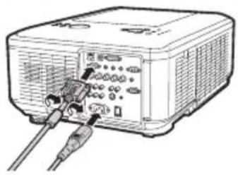
- Connect the projector to the computer and plug the power cord into the AC socket of the projector
natural_image
Line drawing of a portable electronic device with ports and cables (no text or symbols)When connecting equipment other than a computer, see pages 22 and 23.
→PP. 21, 25
4. Turn the projector on
Switch the MAIN POWER switch on the projector to "ON" and, after the POWER indicator has turned red, press STANDBY/ON on the projector or on the remote control.
On the projector On the remote control


→P.28
Easy Start (Continued)
5. Adjust the angle
Adjust the projector angle:
- Shift the lens horizontally and vertically.
- Press H&V LENS SHIFT (▲/▼/◄/►) on the projector.
- Press LENS SHIFT and then press ▲, ▼, ◀ or ▶ on the remote control.
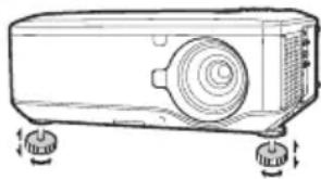
- Adjust the projector angle by rotating the adjustment feet.
natural_image
Line drawing of a projector with two wheels and a circular vent (no text or symbols)→P.30
6. Adjust the focus and the zoom
1 Press FOCUS +/- on the projector or on the remote control to adjust the focus.
2 Press ZOOM +/- on the projector or on the remote control to adjust the zoom.
→P. 31
7. Correcting the image distortion due to the projection angle
1 Press MENU to display the menu screen.
2 Press ◀ or ▶ to select "SCR-ADJ".
3 Press ▲ or ▼ to select "Keystone".
4 Press ◀ or ▶ to adjust the Keystone Correction.
→P.32
8. Select the Input mode
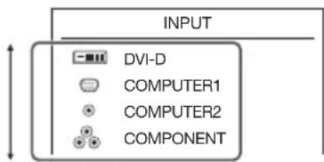
Press INPUT to display the INPUT list. Use ▲/▼ to select the Input mode.
INPUT list
On the projector

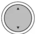
On the remote control


→P.33
9. Turn the computer on
10. Turn the power off
Press STANDBY/ON on the projector or on the remote control, and then press the button again while the confirmation message is displayed to put the projector into Standby mode.
On the projector On the remote control


On-screen display

Enter STANDBY Mode?
Yes : Press Again
No : Please Wait
- You can unplug the power cord or switch the MAIN POWER switch to “OFF” even if the projector is operating.
- Even if you unplug the power cord or switch the MAIN POWER switch to "OFF", the cooling fan continues to run for a while.
→P.28
Setting Up the Projector
Video Setup
If using this projector outside the U.S.A., please change setting to "0 IRE" in Video Setup. (See page 48.)
Setting Up the Projector
For optimal image quality, position the projector perpendicular to the screen with the projector's feet fl at and level. Doing so will eliminate the need for Keystone correction and provide the best image quality. (See page 32.)
Standard Setup (Front Projection)
Place the projector at the required distance from the screen according to the desired picture size. (For details, refer to "SETUP MANUAL" contained on the supplied CD-ROM.)
Indication of the Projection Image Size and Projection Distance
XG-PH80W-N
(Example: 16:10 Signal Input (Normal Mode) for the standard zoom lens (AN-PH818EZ))

geo
| Picture Size | Projection Distance (m) | | ------------ | ------------------------ | | 500" | 1077 | | 200" | 673 | | 100" | 269 | | 80" | 135 | | 60" | 108 | | 51" | 81 | | 77" | -16 | | 101" | -13 | | 127" | -16 | | 252" | -33 | | 821" | -83 | | 822" | -25 |XG-PH80X-N
(Example: 4:3 Signal Input (Normal Mode) for the standard zoom lens (AN-PH818EZ))

geo
| Picture Size | Projection Distance | | ------------ | ------------------- | | 500" | 1270 m | | 200" | 508 m | | 100" | 254 m | | 80" | 203 m | | 60" | 152 m | | 48" | 36 m | | 64" | 48 m | | 80" | 60 m | | 160" | 120 m | | 406 cm | 305 cm | | 122 cm | 91 cm | | 7.1" | -9.5 m | | 9.6" | -12.6 m | | 11.1" | -15.8 m | | 23.9" | -31.4 m | | 59.4" | -78.4 m | | 18.1" | -23.9 m |
Setting Up the Projector (Continued)
Projection (PRJ) Mode
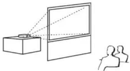
The projector can use any of the 4 projection modes shown in the diagram below. Select the mode most appropriate for the projection setting in use. (You can set the PRJ mode in "SCR-ADJ" menu. See page 49.)
■ Table mounted, front projection [Menu item → "Front"]

natural_image
Simple line drawing of a projector and two human figures (no text or symbols)■ Table mounted, rear projection (with a translucent screen) [Menu item → “Rear”]
natural_image
Diagram showing a projector projecting onto a screen to a seated audience (no text or symbols present)■ Ceiling mounted, front projection [Menu item → "Ceiling + Front"]

natural_image
Simple line drawing of a projector projecting onto a screen, with two silhouettes of people below (no text or symbols)■ Ceiling mounted, rear projection (with a translucent screen) [Menu item → “Ceiling + Rear”]

natural_image
Diagram showing a projector projecting onto a screen to an audience, with no text or symbols present.■ Ceiling-Mount Setup
Before mounting the projector, contact your nearest Sharp Authorized Projector Dealer or Service Center to obtain the recommended ceiling-mount adaptor and unit (sold separately).
Connecting the Projector to Other Equipment
Before connecting, ensure that the power cord of the projector is unplugged from the AC outlet and turn off the equipment to be connected. After making all connections, turn on the projector and then the other pieces of equipment. When connecting a computer, ensure that it is the last equipment to be turned on after all the connections are made.
IMPORTANT: Ensure that the appropriate input mode has been selected on the projector before you turn on the connected equipment.
- For more details of connection and cables, refer to the operation manual of the connected equipment.
- You may need other cables or connectors not listed below.
Terminals on the Projector

| Equipment | Terminal on connected equipment | Cable | Terminal on the projector |
Computer  | RGB output terminal 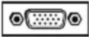 Computer audio output terminal Computer audio output terminal | COMPUTER/ COMPONENT1 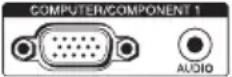 | |
RGB cable (supplied)  | |||
| Computer audio cable ( 3.5 mm stereo minijack, commercially available) | |||
RGB output terminal 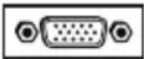 Computer audio output terminal Computer audio output terminal | Mini D-sub 15 pin/5 BNC cable (commercially available)  | COMPUTER/ COMPONENT2 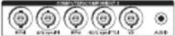 | |
| Computer audio cable ( 3.5 mm stereo minijack, commercially available) | |||
DVI digital output terminal  Computer audio output terminal Computer audio output terminal | DVI Digital cable (commercially available) DVI-D  |  | |
| Computer audio cable ( 3.5 mm stereo minijack, commercially available) |

Note
- When using the 3.5mm mono audio cable, the volume level will be half of when using the 3.5mm stereo audio cable.
- When connecting the projector to a compatible computer other than a PC (VGA/SVGA/XGA/SXGA/UXGA) or Macintosh (i.e. Workstation), a separate cable may be needed. Please contact your dealer for more information.
- See page 71 "Compatibility Chart" for a list of computer signals compatible with the projector. Use with computer signals other than those listed may cause some of the functions to not work.
- A Macintosh adaptor may be required for use with some Macintosh computers. Contact your nearest Macintosh Dealer.
- Depending on the computer you are using, an image may not be projected unless the computer's external output port is switched on (e.g. Press "Fn" and "F5" keys simultaneously when using a SHARP notebook computer). Refer to the specific instructions in your computer's operation manual to enable your computer's external output port.
Connecting the Projector to Other Equipment (Continued)
| Equipment | Terminal on connected equipment | Cable | Terminal on the projector |
Video equipment, Camera, Video game     | DVI digital output terminal Audio output terminal Audio output terminal | DVI Digital cable (commercially available) | DVI-D |
ø3.5 mm stereo minijack to RCA audio cable (commercially available) | |||
RGB video output terminal Audio output terminal Audio output terminal | 5 BNC cable (commercially available)COMPUT  | TER/COMPONENT2 | |
ø3.5 mm stereo minijack to RCA audio cable (commercially available)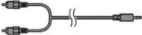 | |||
Component video output terminal Audio output terminal Audio output terminal | Component cable (commercially available) + BNC-RCA adaptor plug (commercially available) | COMPUTER/COMPONENT2 | |
ø3.5 mm stereo minijack to RCA audio cable (commercially available)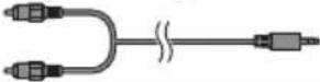 | |||
Component video output terminal Audio output terminal Audio output terminal | Component cable (commercially available)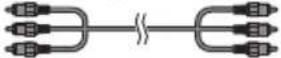 | COMPONENT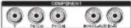 | |
RCA audio cable (commercially available)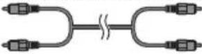 |

Note
- When using the 3.5mm mono audio cable, the volume level will be half of when using the 3.5mm stereo audio cable.
- Select the input signal type of the video equipment when connecting to the COMPUTER/COMPONENT1, 2 or DVI-D terminal. See page 44.
- The HD/C sync and VD terminals may be used depending on the specifications of the DTV decoder connected to this projector. Please refer to the operation manual of the DTV decoder for details.
- The HD/C sync terminal of the 5 BNC terminal is only for TTL signal.
- Depending on specifications of video equipment or the DVI⇔HDMI digital cable, the signal transmission may not work property. (The HDMI specifi cation does not support all connections to video equipment that has HDMI digital output terminal using a DVI⇔HDMI digital cable.)
- For details on compatibility for connection, see support information on DVI connection provided by the video equipment manufacturer.
- When you connect video equipment with a 21-pin RGB output (Euro-scart) to the projector, use a commercially available cable that fits in the projector terminal you want to connect.
- The projector does not support RGBC signals via the Euro-scart.
| Equipment | Terminal on connected equipment | Cable | Terminal on the projector |
Video equipment, Camera, Video game     | D-video output terminal | Cables for a camera or a video game/3 RCA to mini D-sub 15 pin cable (optional, AN-C3CP2)RCA adaptor plug (commercially available) | COMPUTER/COMPONENT1[IMAGE] |
| Audio output terminal | ø3.5 mm stereo minijack to RCA audio cable (commercially available) | ||
| S-video output terminalAudio output terminal | S-video cable (commercially available) S-VIDEO | [IMAGE] | |
| RCA audio cable (commercially available) | |||
| Video output terminalAudio output terminal | Video cable (commercially available) VIDEO | [IMAGE] | |
| RCA audio cable (commercially available) | |||
Monitor RGB input | terminal | RGB cable (supplied or commercially available) | MONITOR OUT[IMAGE] |
Amplifi er Audio input | terminal | ø3.5 mm stereo minijack to RCA audio cable (commercially available) | MONITOR OUT[IMAGE] |

Note
- When using the 3.5mm mono audio cable, the volume level will be half of when using the 3.5mm stereo audio cable.
- The audio signal is not output from the speaker of the projector when the audio cable is connected to the audio output terminal.
- Video signal for monitor output is analog RGB signal as well as component signal (COMPUTER/COMPONENT1, 2). DVI input video signals would not be output.
Controlling the Projector by a Computer
When the RS-232C terminal on the projector is connected to the RS-232C serial terminal on the computer, or when the LAN terminal on the projector is connected to the LAN terminal on the computer, the computer can be used to control the projector. Refer to the "SETUP MANUAL" contained on the supplied CD-ROM for details.
When connecting to a computer using an RS-232C serial control cable


Note
- When you establish the connection shown above, set "LAN/RS232C" in "Ex. Setting" of the "PRJ-ADJ" menu to "RS232C".
- The RS-232C function may not operate if your computer terminal is not correctly set up. Refer to the operation manual of the computer for details.
- Refer to "SETUP MANUAL" contained on the supplied CD-ROM for the RS-232C specifications and commands.

Info
- Do not connect the RS-232C cable to a terminal other than the RS-232C terminal on the computer. This may damage your computer or projector.
- Do not connect or disconnect an RS-232C serial control cable to or from the computer while it is on. This may damage your computer.
When connecting to the LAN terminal using a LAN cable
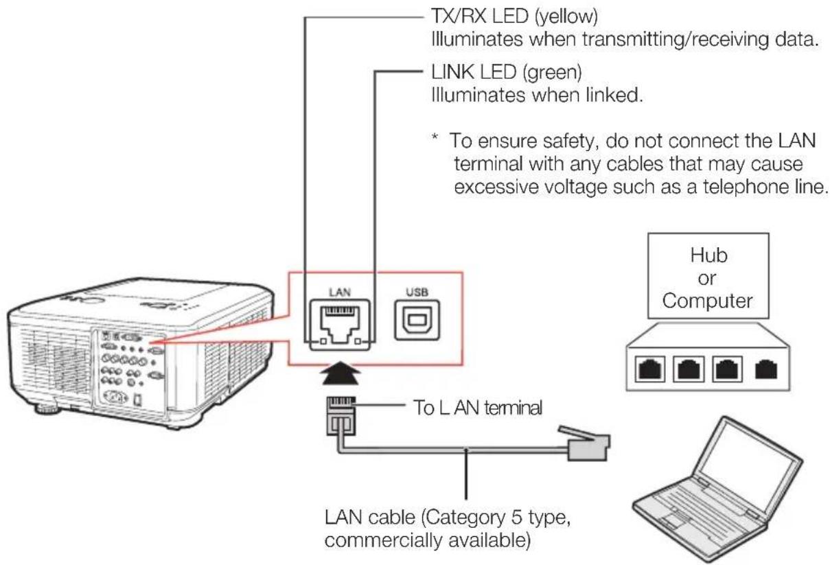

Note
- When you establish the connection shown above, set "LAN/RS232C" in "Ex. Setting" of the "PRJ-ADJ" menu to "LAN".
- When connecting to a hub, use a straight-through Category 5 (CAT.5) type cable (commercially available).
- When connecting to a computer, use a cross-over Category 5 (CAT.5) type cable (commercially available).
Attaching the Optional Lens
When you attach a lens for the first time, skip steps 1 to 3. (When you replace the lens, start from step 1.)
Do not attempt to exchange the lens when the projector is installed hanging from the ceiling. Injury may occur if the lens falls.
1
Press STANDBY/ON on the projector or on the remote control to put the projector into standby mode.
- Switch the MAIN POWER switch on the projector to "OFF".
- Disconnect the power cord and unplug the power cord from the AC socket after the cooling fan stops.
2
Push the LENS RELEASE button all the way in and turn the lens anti-clockwise.
• The lens will be disengaged.

Note
- If the anti-theft screw is used to secure the lens, the lens cannot be removed when the LENS RELEASE button is pressed. In this case, remove the anti-theft screw first.
3
Pull the lens out slowly.
4
Remove the lens cap from a replacement lens.
- Start with this step when you set a lens for the first time.
STANDBY/ON button

LENS RELEASE buttonLENS RELEASE button

natural_image
Illustration of hands using a tool to interact with a device (no text or symbols visible)
natural_image
Diagram of a projector with a hose inserted into a housing component (no text or symbols)
Info
- If you try to attach the lens to the projector without removing this cap, the optional lens attachment part can be damaged.

natural_image
Diagram of a mechanical component with arrows indicating assembly or transformation (no text or symbols)5
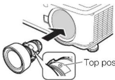
Insert the replacement lens with the top position mark on it facing up, and then turn the lens clockwise until you hear a click sound.
- Make sure that the lens cannot be released even when you try to turn the lens anti-clockwise and pull it out.
Top position markTop positio

natural_image
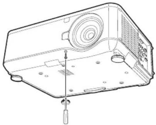
Hand holding a circular component with an arrow indicating rotation (no text or symbols)Using the Anti-Theft Screw
- The lens is secured by the above method, but for added security, an anti-theft screw is supplied to secure the lens more tightly.
- The screw is designed to be rather long, and to secure the screw, give it about 40-50 turns.
natural_image
Technical line drawing of a device casing with screwdriver and ventilation slots (no text or symbols)Connecting the Power Cord
Plug the supplied power cord into the AC socket on the side of the projector. Then plug into AC outlet.

Turning the Projector On/Off
Turning the Projector On
Note that the connections to external equipment and power outlet should be done before performing the operations written below. (See pages 21 to 25.)
Remove the lens cap. Then switch the MAIN POWER switch on the projector to "ON" and, after the POWER indicator has turned red, press STANDBY/ON on the projector or on the remote control.
• The POWER indicator illuminates green.
• After the LAMP indicator illuminates, the projector is ready to start operation.

Note
- About the LAMP Indicator
The LAMP indicator illuminates to indicate the status of the lamp. (See page 64 for details.)
Green or orange: The lamp is on.
Blinking in green or orange: The lamp is warming up.
Red: The lamp is shut down abnormally or the lamp should be replaced.
- When you switch on the projector, a slight fl ickering of the image may be experienced within the first minute after the lamp has been illuminated. This is normal operation as the lamp's control circuitry is stabilizing the lamp output characteristics. It should not be regarded as faulty operation.
- If the projector is put into Standby mode and immediately turned on again, the lamp may take some time to start projection.
- When Security Lock is set, the password input box appears. To cancel the password setting, input the password that you have already set. See page 51 for details.
Turning the Power Off (Putting the Projector into Standby Mode)
Press STANDBY/ON on the projector or on the remote control, then press that button again while the confirmation message is displayed, to put the projector into Standby mode.
- The projector cannot be turned on while cooling.

Info
- When "Auto Restart" is set to "On": If the power cord is unplugged from the outlet or the breaker switch is turned off when the projector is on, then the projector automatically turns on when the power cord is plugged into the AC outlet or the breaker switch is turned on. (See page 52.)
- English is the factory default language. If you want to change the on-screen display to another language, change the language according to the procedure on page 49.

On-screen display (confirmation message)

Enter STANDBY Mode?
Yes : Press Again
No : Please Wait

Info
Direct Power Off function:
- You can unplug the power cord or switch the MAIN POWER switch to "OFF" even if the cooling fan is still running.
-
If you turn the power back on in the cases shown below, the lamp will take a longer time to light up than usual:
-
When the power cord is unplugged during operation
- When the MAIN POWER switch is turned "OFF" during operation
Shifting the Lens
In addition to the zoom function and adjustment of projection angle using the adjustment feet, you can adjust the position of the projection using the lens shift function. This is a useful function in cases such as when the screen cannot be moved.
When moving upward or downward

When moving in the left and right direction

Adjustable range
- The adjustable range is shown below.
Horizontal range: ±10%
Vertical range: +50% (AN-PH814EZ, AN-PH818EZ, AN-PH823EZ, AN-PH845EZ)/0% (AN-PH808EX)
The adjustable range has limitations even within the range shown above.
- The image can be adjusted as shown on the diagram.
AN-PH814EZ, AN-PH818EZ, AN-PH823EZ, AN-PH845EZ
Position of the image when the image is centered, both vertically and horizontally, in lens shift

H : Height of the image
W : Width of the image
AN-PH808EX
Position of the image when the image is placed at the bottom vertically and is centered horizontally in lens shift

H : Height of the image
W : Width of the image
Image Projection (Continued)
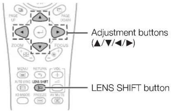
1
Press H&V LENS SHIFT (▲/▼/◄/►) on the projector, or press LENS SHIFT and ▲/▼/◄/► on the remote control, to adjust the image position.
▼On-screen display


Using the Adjustment Feet
- When the position of the projected image cannot be adjusted with the lens shift function, use the adjustment feet to adjust the projected angle.
- The height of the projector can be adjusted using the adjustment feet when the screen is located higher than the projector, the screen is inclined or when the installation site is slightly inclined.
• Install the projector so that it is as perpendicular to the screen as possible.
1
Rotate the adjustment feet to adjust the projected angle.
- The projector is adjustable up to approximately 10 degrees.
[Non-Text]
Warning!
- Do not hold the lens when projector angle is adjusted.
- Use caution not to pinch your finger in the space between the adjustment foot and the projector when the projector angle is lowered.

Adjusting the Focus
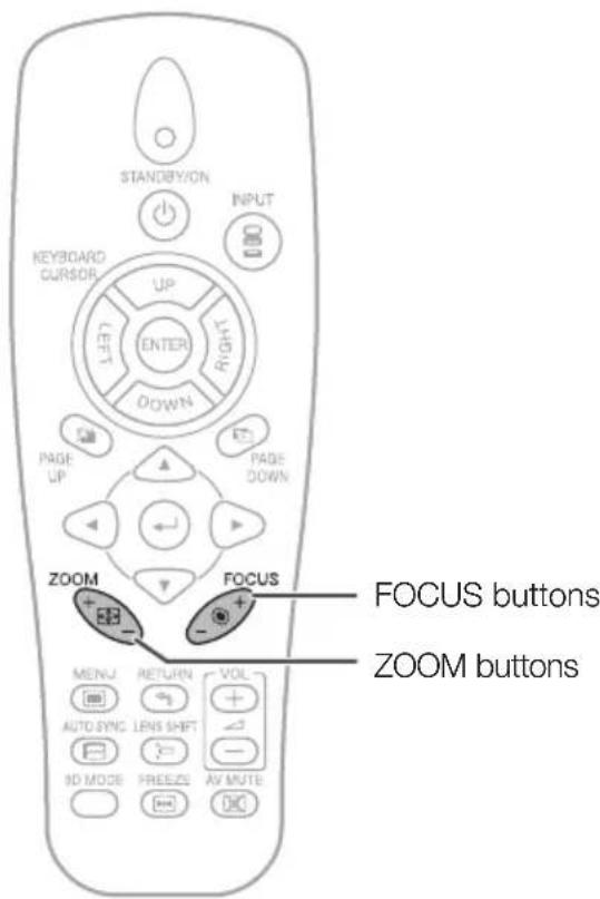
Press FOCUS +/- on the projector or on the remote control to adjust the focus.

Info
- It is recommended that the focus be adjusted after the projector has warmed up for at least 30 minutes.
Adjusting the Projected Image Size
Press ZOOM +/- on the projector or on the remote control to adjust the projected image size.

Note
- For fi ne adjustments, when H&V LENS SHIFT, FOCUS or ZOOM is pressed, the projected image moves a small amount in the desired direction for approximately one second. Hold down the buttons to move the projected image quickly.

Correcting Trapezoidal Distortion
When the image is projected either from the top or from the bottom towards the screen at an angle, the image becomes distorted trapezoidally. The function for correcting trapezoidal distortion is called Keystone Correction.


Note
- The Keystone Correction can be adjusted up to an angle of approximately ±30 degrees and the screen can also be set up to an angle of approximately ±30 degrees.
1 Press MENU to display the menu screen, and then press ◀ or ▶ to select "SCR-ADJ".
2 Press ▲ or ▼ to select "Keystone".
3 Press ◀ or ▶ to adjust the Keystone Correction.
4 Press ▼ to select "Image Resizing".
- Only when "Keystone" is set to the values other than "0", "Image Resizing" works.
5 Press ◀ or ▶ to correct the image distortion.
6 Press MENU.
• The menu screen will disappear.

Info
- While adjusting the image using Keystone Correction, straight lines and the edges of the image may appear jagged.
On-screen display (Keystone Correction mode)
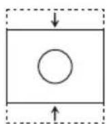
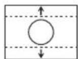
Keystone


Shrinks upper side. (Move the slide bar in the + direction.)

natural_image
Simple geometric diagram showing a square with a circle inside and two dashed arrows pointing outward (no text or symbols)Shrinks lower side. (Move the slide bar in the - direction.)
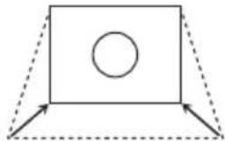
natural_image
Simple geometric diagram showing a rectangle with a circle inside and two dashed lines extending from its corners (no text or symbols)On-screen display (Image Resizing mode)
Image Resizing


Shrinks the image vertically. (Move the slide bar in the + direction.)
Enlarges the image vertically. (Move the slide bar in the - direction.)
Switching the Input Mode
Select the appropriate Input mode for the connected equipment.
Press INPUT on the projector or on the remote control to display the INPUT list.
INPUT list
| INPUT | |
| DVI-D | |
| COMPUTER1 | |
| COMPUTER2 | |
| COMPONENT | |
| S-VIDEO | |
| VIDEO | |
- While the INPUT list is displayed, follow the procedure below to switch the input mode.
- Press ▲/▼ to select the desired input mode and then press ← (ENTER).
- If (ENTER) is not pressed, the projector switches to the selected input mode in a few seconds.

Note
- When no signal or non-supported signal is received, "NO SIGNAL" will be displayed.
Adjusting the Volume
Press VOL +/- on the remote control to adjust the volume.
On-screen display

Volume 1


Note
- Pressing VOL- will lower the volume.
- Pressing VOL+ will raise the volume.
- When the projector is connected to external equipment, the volume level of the external equipment changes in accordance with the volume level of the projector. Set the projector's volume to the lowest level when turning the projector on/off or when changing the input signal.
- When you do not want to output the sound from the projector's speaker while the projector is connected to external equipment, set "Speaker" in "Audio" of the "PRJ-ADJ" menu to "Off". (See page 53.)
- The audio signal is not output from the internal speaker when connecting the audio cable to the MONITOR OUT (AUDIO) terminal.
Displaying the Black Screen and Turning Off the Sound Temporarily
Press AV MUTE on the remote control to temporarily display a black screen and turn off the sound.
On-screen display
AV MUTE

Note
- Pressing AV MUTE again will turn the projected image back on.
Image Projection (Continued)
Resize Mode
This function allows you to modify or customize the Resize mode to enhance the input image. You can set the Resize mode in "SCR-ADJ" menu. See page 49.
1 Press MENU to display the menu screen, and then press ◀ or ▶ to select "SCR-ADJ".
2 Press ▲ or ▼ to select "Resize".
3 Press ◀ or ▶ to adjust the desired Resize mode and then press ← (ENTER).


Note
- The RESIZE function that can be selected varies depending on the input signal (resolution and vertical frequency).
Resize Mode
| RESIZE Output screen image | |
Normal The image is displayed with the original aspect ratio.  | |
Full The image is displayed at full-screen.  | |
16:9 An image compressed from a 16:9 aspect ratio to a 4:3 aspect ratio is restored to a 16:9 aspect ratio and displayed at full-screen. 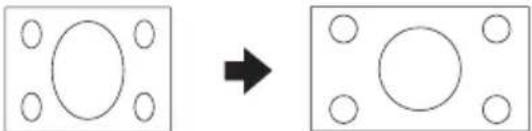 | |
| RESIZE Output | screen image |
4:3 An image stretched from a 4:3 aspect ratio to a 16:9 aspect ratio is restored to a 4:3 aspect ratio.  | |
Native The image is displayed according to the original input signal. “Native” cannot be selected when the input mode is VIDEO or S-VIDEO.  | |
About Copyrights
- When using the Resize function to select an image size with a different aspect ratio to a TV program or video image, the image will look different from its original appearance. Keep this in mind while choosing an image size.
- The use of the Resize or Keystone Correction function to compress or stretch the image for commercial purposes/public displays in a café, hotel, etc. may be an infringement of copyright protected by law for copyright holders. Please use caution.
Operating with the Remote Control
Auto Sync (Auto Sync Adjustment)
Auto Sync function works when detecting input signal after the projector turns on.
Press AUTO SYNC to manually adjust with Auto Sync function.

Note
- When the optimum image cannot be achieved with Auto Sync adjustment, use manual adjustments. (See page 46.)
Freezing a Moving Image
1 Press FREEZE.
• The projected image is frozen.
2 Press FREEZE again to return to the moving image from the currently connected device.

Using the Remote Control to Operate the Computer
When connecting the projector and the computer with a USB cable, you can use the remote control to operate the computer.
Connecting with a USB cable

The computer can be operated in the following way after it is connected.
■ When moving the cursor
Same as the [ ↑ / ↓ /←/→ ] keys on a computer keyboard.
Press KEYBOARD CURSOR (UP/DOWN/LEFT/RIGHT).
■ When using [Enter]
Same as the [Enter] key on a computer keyboard.
Press KEYBOARD CURSOR (ENTER).
■ When using [Page Up] or [Page Down]
Same as the [Page Up] and [Page Down] keys on a computer keyboard.
Press PAGE UP or PAGE DOWN.
![SHARP XG-PH80WN - ■ When using [Page Up] or [Page Down] - 1](/content/2026/05/1065914/images/23d8b4c3d5c4c8b3c87abb089afccc2e76b5ac758f0c6a9cc278fd0e8e4cccff.jpg)
Note
- This function only works with the Microsoft® Windows® OS and Mac OS® that support USB.
- Confirm that the computer recognizes the USB connection.

KEYBOARD CURSOR (ENTER) button
KEYBOARD CURSOR (UP/DOWN/LEFT/RIGHT) buttons
PAGE DOWN button PAGE UP button
Menu Items
The following shows the items that can be set in the projector.
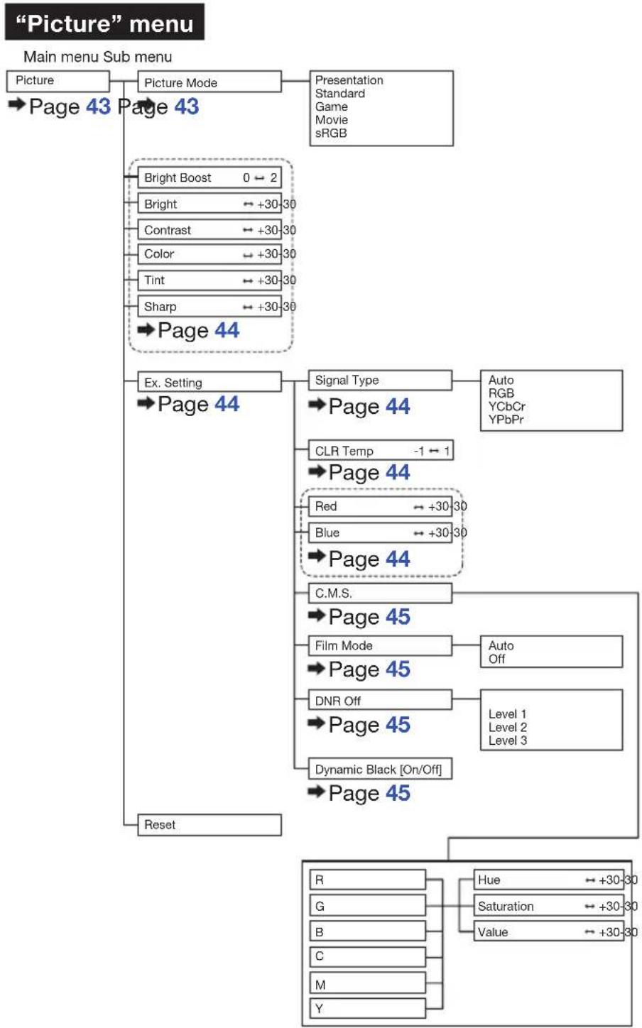
flowchart
graph TD
    A["Main menu Sub menu"] --> B["Picture"]
    B --> C["Picture Mode"]
    C --> D["Presentation Standard Game Movie sRGB"]
    C --> E["Bright Boost 0 ← 2"]
    C --> F["Bright ← +30→30"]
    C --> G["Contrast ← +30→30"]
    C --> H["Color ← +30→30"]
    C --> I["Tint ← +30→30"]
    C --> J["Sharp ← +30→30"]
    C --> K["Page 44"]
    K --> L["Ex. Setting"]
    L --> M["Page 44"]
    M --> N["Signal Type"]
    N --> O["Auto RGB YCbCr YPbPr"]
    M --> P["CLR Temp -1 ← 1"]
    M --> Q["Page 44"]
    Q --> R["Red ← +30→30"]
    Q --> S["Blue ← +30→30"]
    Q --> T["Page 44"]
    T --> U["C.M.S."]
    U --> V["Page 45"]
    V --> W["Film Mode"]
    W --> X["Auto Off"]
    V --> Y["Page 45"]
    Y --> Z["DNR Off"]
    Y --> AA["Page 45"]
    AA --> AB["Dynamic Black [On/Off"]]
    AA --> AC["Page 45"]
    AC --> AD["Reset"]
    AD --> AE["R"]
    AD --> AF["G"]
    AD --> AG["B"]
    AD --> AH["C"]
    AD --> AI["M"]
    AD --> AJ["Y"]
    AE --> AK["Hue ← +30→30"]
    AE --> AL["Saturation ← +30→30"]
    AE --> AM["Value ← +30→30"]
"Signal adjustment (SIG-ADJ)" menu
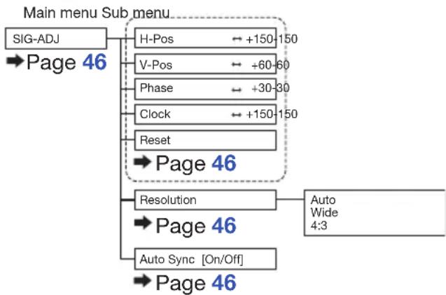
flowchart
graph TD
    A["Main menu Sub menu"] --> B["SIG-ADJ"]
    B --> C["Page 46"]
    C --> D["H-Pos ← +150-150"]
    C --> E["V-Pos ← +60-60"]
    C --> F["Phase ← +30-30"]
    C --> G["Clock ← +150-150"]
    C --> H["Reset"]
    H --> I["Page 46"]
    I --> J["Resolution"]
    J --> K["Auto Wide 4:3"]
    I --> L["Page 46"]
    L --> M["Auto Sync [On/Off"]]
    L --> N["Page 46"]
"Video" menu

flowchart
graph TD
    A["Main menu Sub menu"] --> B["Video"]
    A --> C["Overscan [On/Off"]]
    B --> D["Page 47"]
    C --> E["Page 47"]
    C --> F["Video System Auto"]
    F --> G["PAL SECAM NTSC4.43 NTSC3.58 PAL-M PAL-N PAL-60"]
    F --> H["Video Setup"]
    H --> I["0 IRE 7.5 IRE"]
    H --> J["Closed Caption"]
    J --> K["CC1 Off"]
    H --> L["Page 48"]
    L --> M["Page 48"]
"Screen adjustment (SCR-ADJ)" menu

flowchart
graph TD
    A["SCR - ADJ"] --> B["Page 49"]
    B --> C["Language"]
    C --> D["English Puccski"]
    C --> E["Deutsch polski"]
    C --> F["Espanol magyar nyelv"]
    C --> G["Nederlands Türke"]
    C --> H["Français 汉语"]
    C --> I["Italiano 한국어"]
    C --> J["Svenska 日本語"]
    C --> K["Português"]
    B --> L["Background"]
    L --> M["Page 49"]
    M --> N["Logo Custom Blue None"]
    B --> O["PRJ Mode"]
    O --> P["Page 49"]
    P --> Q["Front Rear Ceiling + Front Ceiling + Rear"]
    B --> R["Resize"]
    R --> S["Page 49"]
    S --> T["Normal Full 4:3 16:9 Native"]
    B --> U["Keystone ← +80→80"]
    U --> V["Page 50"]
    V --> W["Image Resizing ← +30→30"]
    W --> X["Page 50"]
    X --> Y["Wall Color Whiteboard"]
    Y --> Z["Page 50"]
    Z --> AA["Blackboard Off"]
    Z --> AB["Security Lock [Enable/Disable"]]
    AB --> AC["Page 51"]
    AB --> AD["Keypad Lock"]
    AD --> AE["Page 51"]
    AD --> AF["Image Capture Save Image Delete"]
    AB --> AG["Page 51"]
"Projector adjustment (PRJ-ADJ)" menu

flowchart
graph TD
    A["PRJ - ADJ"] --> B["Auto Search [On/Off"]]
    B --> C["Page 52"]
    C --> D["Auto Power Off [On/Off"]]
    D --> E["Page 52"]
    E --> F["Auto Restart [On/Off"]]
    F --> G["Page 52"]
    G --> H["Eco + Quiet [On/Off"]]
    H --> I["Page 52"]
    I --> J["Lamp Mode Both Lamps"]
    J --> K["Page 53"]
    K --> L["Lamp1 Only Lamp2 Only Equal Use"]
    L --> M["Audio Volume"]
    M --> N["Page 53"]
    N --> O["Ex. Setting"]
    O --> P["Page 53"]
    P --> Q["Fan Mode"]
    Q --> R["Page 53"]
    R --> S["STANDBY Mode"]
    S --> T["Page 53"]
    T --> U["STANDBY Audio Out [On/Off"]]
    U --> V["Page 53"]
    V --> W["Filter Message"]
    W --> X["Page 54"]
    X --> Y["3D MODE"]
    Y --> Z["Page 54"]
    Z --> AA["DLP® Link™ [On/Off"]]
    AA --> AB["Page 59"]
    AB --> AC["DLP® Link™ Invert"]
    AC --> AD["Page 59"]
    AD --> AE["LAN/RS232C"]
    AE --> AF["Network"]
    AF --> AG["Page 54"]
    AG --> AH["Link DHCP Client [On/Off"] IP Address Subnet Mask Gateway DNS]
    A --> AI["Reset"]
    AI --> AJ["Page 55"]
    AJ --> AK["All Reset"]
    AK --> AL["Page 55"]
    AL --> AM["Information INPUT"]
    AM --> AN["Page 55"]
    AN --> AO["Signal Info Lamp Timer (Life) Lamp1 Lamp2 Filter Timer Model Name Software Version"]
Using the Menu Screen
Adjustment buttons (▲/▼/◄/►)

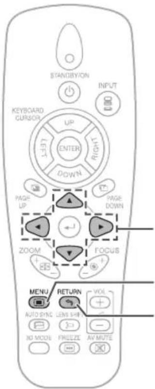
Adjustment buttons

MENU button
RETURN button
- Press RETURN to return to the previous screen when the menu is displayed.
Menu Selections (Adjustments)
Example: Adjusting "Bright".
This operation can also be performed by using the buttons on the projector.
1
Press MENU.
• The menu screen is displayed.
2
Press ▶ or ◀ and select
"Picture" to adjust.
Example: "Picture" screen menu for COMPUTER (RGB) input

Using the Menu Screen (Continued)
3 Press ▲ or ▼ and select "Bright" to adjust.
• The selected item is highlighted.

Items to be adjusted

4 Press ◀ or ▶ to adjust the item selected.
• The adjustment is stored.

5 Press MENU.
• The menu screen will disappear.
Picture Adjustment ("Picture" Menu)
Menu operation → Page 41
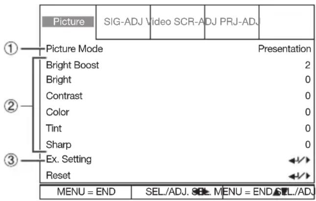

① Selecting the Picture Mode
| Selectable items | Description | The default settings of each item when selecting Picture Mode | |
| CLR Temp Bright Boost | |||
| Presentation | Brightens portions of image for more enhanced presentations. | 0 | 2 |
| Standard For | standard image 0 1 | ||
| Game Gives | sharpness to the projected image. | 0 | 1 |
| Movie Gives | natural tint to the projected image. | -1 | 0 |
| sRGB* | For high fidelity reproduction of images from a computer. | - | - |
- "sRGB" is displayed only when RGB signal is input.
- You can set or adjust each item in the “Picture” menu to your preference. Any changes you make are retained in memory.

Note
- *sRGB is an international standard of color reproduction regulated by the IEC (International Electrotechnical Commission). As the fixed color area has been decided by the IEC, the images are displayed in a natural tint based on an original image, when “sRGB” is selected. You cannot set the items, “Red”, “Blue”, “CLR Temp”, “Bright Boost”, “C.M.S.”, when “sRGB” is selected.

Info
- When "sRGB" is selected, the projected image may become dark, but this does not indicate a malfunction.
Picture Adjustment (“Picture” Menu) (Continued)
Menu operation → Page 41
② Adjusting the Image
| Adjustment items | ◀ button ▶ button | |
| Bright Boost | To improve color reproduction, lower bright boost setting. | To increase brightness, increase bright boost setting. |
| Bright For less | brightness. | For more brightness. |
| Contrast For less | contrast. | For more contrast. |
| Color*1 | For less color intensity. | For more color intensity. |
| Tint*1 | For making skin tones purplish. | For making skin tones greenish. |
| Sharp*1 | For less sharpness. | For more sharpness. |
*1 Not selected in the RGB input mode.

Note
- "Bright Boost" cannot be set when "sRGB" is selected.
- To reset all adjustment items, select "Reset" and press ← (ENTER).
③ Using the Ex. Setting
Select "Ex. Setting" and then press ENTER to set "Signal Type", "CLR Temp", "Red", "Blue", "C.M.S.", "Film Mode", "DNR" or "Dynamic Black".
④ Signal Type Setting
This function allows you to select the input signal for COMPUTER/COMPONENT1, 2 or COMPONENT.
| Selectable items | Description |
| Auto Input signals are automatically recognized as RGB or component. | |
| RGB Set when RGB signals are received. | |
| YCbCr Set when Component signals (480I/480P/576I/576P) are received. | |
| YPbPr Set when Component signals (720P/1080I/1080P) are received. | |
⑤ Adjusting the Color Temperature
| Selectable items | Description |
| -1 | For lower color temperature for warmer, reddish incandescent-like images. |
| 0 | |
| 1 | For higher color temperature for cooler, bluish, fluorescent-like images. |

Note
- "CLR Temp" cannot be set when "sRGB" is selected.
- Values on "CLR Temp" are only for general standard purposes.
⑥ Adjusting the Red/Blue
| Adjustment items | ◀ button ▶ | button |
| Red For weaker red. For stronger | red. | |
| Blue For weaker blue. | For stronger blue. | |

Note
- "Red" and "Blue" are not adjustable/selectable when selecting "sRGB".
⑦ Adjusting the Colors
This function adjusts each of the six main colors that comprise the color wheel, altering their “Hue”, “Saturation”, or “Value”.
| Selectable items | Description |
| Hue Sets the hue of | the main colors. |
| Saturation Sets the | saturation of the main colors. |
| Value Sets the bright | tness of the main colors. |
Adjusting "Hue", "Saturation", or "Value".
1 Select "C.M.S." in "Ex. Setting" of the "Picture" menu and then press ← (ENTER).
2 Select "R", "G", "B", "C", "M" or "Y" and then press ← (ENTER).
3 Press ▲ or ▼ to select either "Hue", "Saturation", or "Value".
4 Select the color to be adjusted with ◀ or ▶.
Example of adjusting the "Hue"
| Main colors | ◀ button | ▶ button |
| R (Red) | Closer to magenta | Closer to yellow |
| G (Green) | Closer to yellow | Closer to cyan |
| B (Blue) | Closer to cyan | Closer to magenta |
| C (Cyan) | Closer to green | Closer to blue |
| M (Magenta) | Closer to blue Closer | to red |
| Y (Yellow) | Closer to red | Closer to green |
- When "Saturation" is selected, the selected color becomes
◀: lighter. ▶: thicker. - When "Value" is selected, the selected color becomes
◀: darker. ▶: brighter.

Note
- "C.M.S." is not selectable when "sRGB" is selected.
⑧ Selecting the Film Mode
This function provides high-quality playback of images originally projected at 24 fps, such as movies on DVDs.
| Selectable items | Description |
| Auto Films are detected automatically. | |
| Off Films are not detected. | |

Note
- This function is available for the following signals.
With COMPUTER/COMPONENT1, 2 or COMPONENT input:
- 480I
-576I - 1080I
With S-VIDEO or VIDEO input:
- All signals
⑨ Reducing Image Noise (DNR)
Video digital noise reduction (DNR) provides high quality images with minimal dot crawl and cross color noise.
| Selectable items | Description |
| Off DNR does not function. | |
| Level 1 | Sets the DNR level for viewing a clearer picture. |
| Level 2 | |
| Level 3 | |

Note
This function is not available for some signals.
⑩ Setting the Dynamic Black
Use this function to improve the black level of the projector.
| Selectable items | Description |
| On The black | level of the projector will be improved. |
| Off Dynamic | Black does not function. |
Signal Adjustment ("SIG-ADJ" Menu)
Menu operation → Page 41

① Adjusting the Computer Image
If the optimum image cannot be obtained with Auto Sync adjustment, use the SIG-ADJ function.
| Selectable items | Description |
| H-Pos Centers | the on-screen image by moving it to the left or right. |
| V-Pos Centers | the on-screen image by moving it up or down. |
| Phase Adjusts | horizontal noise (similar to tracking on your VCR). |
| Clock Adjusts | vertical noise. |

Note
- To reset all adjustment items, select "Reset" and press ← (ENTER).
- The adjustable range of "H-Pos" (H-Position) and "V-Pos" (V-Position) may vary depending on the screen resolution of the computer.
② Setting the Resolution
| Selectable items | Description |
| Auto | Input signal resolution is automatically recognized. |
| Wide | Set when the Wide signal is received. |
| 4:3 | Set when the 4:3 signal is received. |
③ Auto Sync (Auto Sync Adjustment)
| Selectable items | Description |
| On Auto Sync | adjustment will occur when the projector is turned on or when the input signals are switched, when connected to a computer. |
| Off Auto Sync | adjustment is not automatically performed. |

Note
• Auto Sync adjustment is also performed by pressing AUTO SYNC.
- The Auto Sync adjustment may take some time to complete, depending on the image of the computer connected to the projector.
- When the optimum image cannot be achieved with Auto Sync adjustment, use manual adjustments.
Video Adjustment ("Video" Menu)
Menu operation → Page 41

①Setting the Overscan
This function allows you to set the overscan area (display area).
| Selectable items | Description |
| On The input | area is displayed without the screen edges. |
| Off The whole | input area is displayed. |

Note
- This function is available for the following signals.
With COMPUTER/COMPONENT1, 2, COMPONENT or DVI-D input:
- 480P
-576P
-720P
- 1080I/1080P
- If noise appears at the screen edges when "Off" is selected, set the function to "On".
- Also see "About Copyrights" on page 35.
② Setting the Video System
The video input system mode is factory preset to "Auto"; however, a clear picture from the connected audio-visual equipment may not be received, depending on the Video signal difference.
In that case, switch the Video signal.
| Selectable items |
| Auto |
| PAL |
| SECAM |
| NTSC4.43* |
| NTSC3.58 |
| PAL-M |
| PAL-N |
| PAL-60 |
* When reproducing NTSC signals in PAL video equipment.

Note
- The Video signal can only be set in S-VIDEO or VIDEO mode.
- When “Video System” is set to “Auto”, you may not receive a clear picture due to signal differences. Should this occur, switch to the video system of the source signal.
Video Adjustment (“Video” Menu) (Continued)
Menu operation → Page 41

Setting the Video Setup
| Selectable items | Description |
| 0 IRE Sets the black level to 0 IRE. | |
| 7.5 IRE Sets the black level to 7.5 IRE. | |

Note
- This function is available for the following signals.
With COMPUTER/COMPONENT1, 2 or COMPONENT input:
- 480I
With S-VIDEO or VIDEO input:
- NTSC3.58

Closed Caption

Info
- This function is available for NTSC3.58 signal.
- This function is available in the following cases only:
| Resize mode Keystone Correction | |
| NormalFull4:3 | -40 - +40 |
| 16:9 -12 - +12 | |
- “Closed Caption” is a system which allows conversations, narration, and sound effects in TV programs (Limited regions) and home videos to be viewed as captions on the screen.
- Not all programs and videos will offer closed captioning. Please look for the symbol to ensure that captions will be shown.
| Selectable items | Description |
| CC1 | Closed Caption mode for CH1 data |
| Off — |

Note
- Closed Caption may malfunction (white blocks, strange characters, etc.) if signal conditions are poor or if there are problems at the broadcast source. This does not necessarily indicate a problem with the projector.
- If any button is pressed to call up the on-screen display while viewing a Closed Caption broadcast, the closed captions will disappear.
Adjusting the Projected Image ("SCR-ADJ" Menu)
Menu operation → Page 41

① Selecting the On-screen Display Language
The projector can switch the on-screen display language among 15 languages.
| English | Русский |
| Deutsch | polski |
| Español | magyar nyelv |
| Nederlands | Türkçe |
| Français | 汉语 |
| Italiano | 한국어 |
| Svenska | 日本語 |
| Português |
② Selecting the Background Image
| Selectable items | Description |
| Logo Sharp logo screen | |
| Custom User customized image (e.g. company logo) | |
| Blue Blue screen | |
| None | Black screen |

Note
- When "Custom" is selected, an image saved using "Image Capture" can be displayed as a background image.
③ Reversing/Inverting Projected Images
| Selectable items | Description |
| Front | Normal image (Projected from the front of the screen) |
| Rear | Reversed image (Projected from the rear of the screen or with a mirror) |
| Ceiling + Front | Inverted image (Projected from the front of the screen with an inverted projector) |
| Ceiling + Rear | Reversed and inverted image (Projected with a mirror) |
See page 20 for details of Projection (PRJ) Mode.
④ Setting the Resize Mode
Use this function to stretch the image vertically or horizontally or when the edges of the image cannot be seen.

Note
- For details of the Resize mode, see pages 34 and 35.
Adjusting the Projected Image ("SCR-ADJ" Menu) (Continued)
Menu operation → Page 41
⑤ Keystone Correction
When the image is projected either from the top or from the bottom towards the screen at an angle, the image becomes distorted trapezoidally. The function for correcting trapezoidal distortion is called Keystone Correction.
Select "Keystone" on the "SCR-ADJ" menu and adjust with the slide bar.
See page 32 for details of “Correcting Trapezoidal Distortion”.


Note
- The Keystone Correction can be adjusted up to an angle of approximately ± 30 degrees.
⑥ Image Resizing
For correcting the image distortion which cannot be corrected with “Keystone”. Only when “Keystone” is set to the values other than “0”, “Image Resizing” can be adjusted.
Select "Image Resizing" on the "SCR-ADJ" menu and adjust with the slide bar.
See page 32 for details of "Correcting Trapezoidal Distortion".
◀ button▶ button

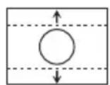
⑦ Selecting the Wall Color
This function allows you to project the image to a colored (white or dark green) surface or wall without using a screen.
| Selectable items | Description |
| Whiteboard Projects | images onto a whiteboard. |
| Blackboard Projects | images onto a blackboard (dark green). |
| Off The Wall Color function is not activated. | |
⑧ Using the Ex. Setting
Select "Ex. Setting" and then press ENTER to set "Security Lock", "Keypad Lock" or "Image Capture".
⑨ Security Lock Function
This function prevents unauthorized use of the projector. Once this function is activated, users must enter the correct password each time the projector is turned on. We suggest you record the password in a safe place where only authorized users have access.

Info
- If you lose or forget your password, contact your nearest Sharp Authorized Projector Dealer or Service Center (see page 76). Even if the product warranty is valid, the password reset will incur a charge.
■ Setting a Password
1 Select "Security Lock", then press ▶when "Disable" is displayed.
- The screen for entering the password appears.
2 Press ▲/▼/◄/► (Adjustment buttons) on the remote control or on the projector to enter the password in "Setting the Password".

3 Enter the same password in "Confir rm Password".
4 Press RETURN to exit.

Note
When the Security Lock is set
- When Security Lock is set, the password input screen appears after the power is turned on. When it appears, enter the right password to start projection.
Input screen for password

■ Canceling a Password
Select "Security Lock", then press ▶ when "Enable" is displayed.
⑩ Keypad Lock Function
Use this function to lock the operation buttons on the projector.
| Selectable items | Description |
| No Turns off | the Keypad Lock function. |
| Yes All buttons | on the projector, except STANDBY/ON, are locked. |
■ Taking the Keypad Lock Off
Hold down ▼ (Adjustment button) on the projector for about 5 seconds.

Info
- Keypad Lock cannot be released while the projector is: displaying the "Menu" screens, in Standby mode, warming up, changing input signals or operating the Auto Sync function, in Freeze mode or on the "Security Lock" screen during warming up.
⑪ Image Capture
This projector allows you to capture projected images (RGB signals) and set them as a startup image, or background image when no signals are being received.

Note
- Images can be captured only when they are from WXGA (1280 × 800) (XG-PH80W-N), XGA (1024 × 768) (XG-PH80X-N) non-interlace signals in COMPUTER/COMPONENT1, 2 or DVI-D mode with “Resize” set to “Normal”.
- Images from equipment connected to VIDEO or S-VIDEO terminal cannot be captured.
- To delete the captured image, select "Yes" in "Delete", and then press ← (ENTER). (See OSD tree image on page 39.)
- An image can be saved for either of the four-segment color wheel or the six-segment one, separately. Each color wheel can save one image.
- When the four-segment color wheel is used, only the image saved for the four-segment color wheel is available.
- When the six-segment color wheel is used, only the image saved for the six-segment color wheel is available.
- Depending on the image type, it may take the projector some 2 minutes to complete the capture.
- Switching input signals during performing Image Capture may result in the failure of the performance of the capture.
Adjusting the Projector Function ("PRJ-ADJ" Men u)
Menu operation → Page 41

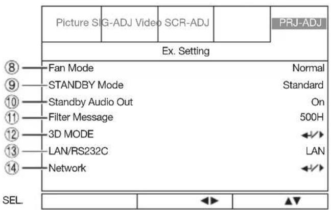
① Detecting the Input Signals Automatically
This function enables the projector to detect the received signal and to switch the Input mode automatically when the power is turned on.
| Selectable items | Description |
| On Automatically searches for and switches to the input mode in which signals are being received. | |
| Off Auto Search does not function. | |

Note
- While the "Auto Search" function is detecting the input signal, pressing a button on the projector or the remote control stops the "Auto Search" function. After the "Auto Search" function finishes completely, press the desired button.
② Auto Power Off Function
| Selectable items | Description |
| On When no | input signal is detected for more than 15 minutes, the projector will automatically enter Standby mode. |
| Off The Auto | Power Off function will be disabled. |
③ Auto Restart Function
| Selectable items | Description |
| On | If the power cord is unplugged from the outlet or the breaker switch is turned off when the projector is on, then the projector automatically turns on when the power cord is plugged into the AC outlet or the breaker switch is turned on. |
| Off The projector does not turn on automatically when the power cord is plugged into the AC outlet or the breaker switch is turned on. | |
To activate the Auto Restart function, you need to switch the MAIN POWER switch on the projector to "ON".
④ Eco+Quiet
| Selectable items | Brightness and Power consumption |
| On Approx. | 83% |
| Off 100% |

Note
- When "Eco+Quiet" is set to "On", the fan sound and power consumption are lower than they are when "Off" is selected. (Projection brightness decreases as shown in the chart.)
⑤ Setting the Lamp Mode
This function allows you to select the usage of the two lamps installed in the projector.
| Selectable items | Description |
| Both Lamps Both lamps are used for greater brightness. | |
| Lamp 1 Only The lamp 1 is used.When the lamp 1 burns out, the lamp 2 automatically switches in use. | |
| Lamp 2 Only The lamp 2 is used.When the lamp 2 burns out, the lamp 1 automatically switches in use. | |
| Equal Use The lamp whose remaining life time is the longer is used. | |

Note
- For lamp protection, this function is not available for several minutes when changing the lamp mode.
⑥ Setting the Audio
You can set the following Audio items.
| Selectable items | Description | |
| Volume You can change the volume level.The adjustable range is 0 to 60. | ||
| Speaker On The audio signal is output from the internal speaker. | ||

Note
- The audio signal is not output from the speaker of the projector when the audio cable is connected to the audio output terminal and you cannot change the setting.
⑦ Using the Ex. Setting
Select "Ex. Setting" and then press ← (ENTER) to set "Fan Mode", "STANDBY Mode", "STANDBY Audio Out", "Filter Message", "3D MODE", "LAN/RS232C" or "Network".
⑧ Fan Mode Setting
This function changes the fan rotation speed.
| Selectable items | Description |
| Normal Suitable for normal environments. | |
| High Set when using the projector at altitudes of approximately 1,200 meters (4,000 feet) or more. | |
When “Fan Mode” is set to “High”, the fan rotation speeds up, and the fan noise becomes louder.
⑨ STANDBY Mode
When set to "Eco", power consumption is reduced in Standby mode.
| Selectable items | Description |
| Standard The monitor output, LAN/RS232C and Network functions are activated even if the projector is in Standby mode. | |
| Eco The monitor output, LAN/RS232C and Network functions are switched off in Standby mode. | |
⑩ STANDBY Audio Out
You can set audio output from the AUDIO OUTPUT terminal of the projector that is in Standby mode.
| Selectable items | Description |
| On The audio | signal is output from the AUDIO OUTPUT terminal in Standby mode. |
| Off The audio | signal is not output from the AUDIO OUTPUT terminal in Standby mode. |

Note
- When "Eco" is selected for "STANDBY Mode", "STANDBY Audio Out" is set to "Off" automatically and you cannot change the setting.
Adjusting the Projector Function (“PRJ-ADJ” Menu) (Continued)
Menu operation → Page 41
⑪ Filter Message
You can select the interval time to display a message for cleaning the filter.
Clean The Filter.
| Selectable items | Description |
| Off Not displaying the message. | |
| 100H/200H/500H/1000H | Select the interval time to display a message. |
12 3D MODE
You can set "DLP® Link™" and "DLP® Link™ Invert". See "Using 3D Viewing Mode" on page 59 for details.
13 Setting the LAN/RS232C
You can select "LAN" or "RS232C" and selected terminal is only used.
| Selectable items | Description |
| LAN The LAN | function is activated. |
| RS232C The | RS-232C function is activated. |
⑭ Setting the Network
Link
| Selectable items | Description |
| Connected | Connected to the network. |
| Disconnected | Disconnected from the network. |
DHCP Client
Connect the LAN cable before turning the projector on. If not, the DHCP Client function does not work. If the DHCP server is not available, set the IP Address, Subnet Mask, Gateway and DNS manually.
| Selectable items | Description |
| On Obtains | confi guration parameters for IPAddress, Subnet Mask, Gateway, and DNS automatically. |
| Off Set the IP | Address, Subnet Mask,Gateway, and DNS manually. |
■ IP Address/Subnet Mask/Gateway/DNS/Apply
| Selectable items | Description |
| IP Address F | Factory default setting:192.168.150.002Enter an IP address appropriate for the network. |
| Subnet Mask | Factory default setting:255.255.255.000Set the subnet mask to the same as that of the computer and equipment on the network. |
| Gateway Factory default setting:000.000.000.000* When not in use, set to “000.000.000.000”. | |
| DNS Factory default setting:000.000.000.000* When not in use, set to “000.000.000.000”. | |
| Apply | Apply and save the new settings. |

Note
- Confirm the existing network's segment (IP address group) to avoid setting an IP address that duplicates the IP addresses of other network equipment or computers. If
"192.168.150.002" is not used in a network with an IP address of "192.168.150.XXX", you don't have to change the projector IP address. - For details about each setting, consult your network administrator.
⑮ Returning to the Default Settings
All Reset
This function allows you to initialize the settings you have made in the projector.

Note
- The following items or menu cannot be initialized.
- Lamp Timer (Life)
- Filter Timer
- Image stored using "Image Capture"
■ Filter Timer Reset
This function allows you to reset the filter timer.

Note
- Make sure to reset the filter timer after cleaning or changing the dust filter. (See page 62.)
16 Information
You can confirm the following items.
| Displayed items | Description |
| INPUT Used input terminal is displayed. | |
| Signal Info Current input signal information is displayed. | |
| Lamp Timer (Life) | Lamp usage time and the remaining lamp life (%) are displayed (Both Lamp1 and Lamp2). See “Lamp Life” below. |
| Filter Timer Filter usage time is displayed. | |
| Model Name Model Name is displayed. | |
| Software Version | Current software version is displayed. |
Lamp Life
| Lamp usage condition | Remaining lamp life | ||
| “Life” 100 | % 5% | ||
| Operated exclusively with “Eco+Quiet” set to “On” | Approx. 3,000 hours | Approx. 150 hours | |
| Operated exclusively with “Eco+Quiet” set to “Off” | Approx. 2,000 hours | Approx. 100 hours | |

Note
- It is recommended that the lamp be changed when the remaining lamp life becomes 5%.
- The lamp life may vary depending on the usage condition.
Precautions on Viewing Stereoscopic 3D Images
Before viewing stereoscopic 3D images, please read this section carefully.

WARNING
■ Under normal conditions, viewing stereoscopic 3D images is safe for any duration that you would normally view your screen. However, some people may experience discomfort. The following precautions are recommended to minimize the potential for experiencing visual problems or any adverse symptoms.
■ Take regular breaks, at least 5 to 15 minutes after every 30 to 60 minutes of stereoscopic 3D viewing.
* Based on the guidelines issued by the 3D Consortium revised December 10, 2008.
- Maintain an appropriate distance from the screen. Viewing from too close a distance can strain your eyes. If you experience eye strain, immediately discontinue viewing.
If you experience any of the following symptoms during viewing:
- nausea
- queasiness/dizziness
- headache
– blurry vision or double vision that lasts longer than few seconds
Do not engage in any potentially hazardous activity (for example, driving a vehicle) until your symptoms have completely gone away. If symptoms persist, discontinue use and do not resume stereoscopic 3D viewing without discussing your symptoms with a physician.
- As you get more comfortable viewing stereoscopic 3D:
- Adjust the parallax on the 3D-video playback equipment. (You may not be able to adjust the parallax on some models of equipment.)
- Adjust the projected image to the most comfortable viewing size by zooming.
(Projecting images on the smallest or largest screen size possible may eliminate the stereoscopic effect and strain your eyes.) - Use the DLP ^® Link ^TM Invert function to properly set the video for your left and right eyes. (For details on using “DLP ^® Link ^TM Invert”, see the section on its operation in this operation manual.)

WARNING
■ The following people should limit stereoscopic 3D viewing:
– Children under 6 years of age (to protect the eye growth process)
- People with a history of photosensitivity
- People with heart disease
- People in poor health
- People who are sleep deprived
- People who are physically tired
– People under the influence of drugs or alcohol
■ Epilepsy
A small percentage of the population may experience epileptic seizures when viewing certain types of images that contain fl ashing patterns of light.
IF YOU OR ANY MEMBER OF YOUR FAMILY HAS A HISTORY OF EPILEPSY
The following people should consult a physician before viewing stereoscopic 3D images.
- Anyone with a history of epilepsy, or who has a family member with a history of epilepsy
– Children under 6 years of age - Anyone who has ever experienced epileptic seizures or sensory disturbances triggered by fl ashing light effects
SOME LIGHT PATTERNS MAY INDUCE SEIZURES IN PERSONS WITH NO PRIOR HISTORY OF EPILEPSY
Discontinue use if you experience any of the following symptoms while viewing stereoscopic 3D images.
- Involuntary movements, eye or muscle twitching
- Muscle cramps
– Nausea, dizziness, or queasiness - Convulsions
- Disorientation, confusion, or loss of awareness of your surroundings
Information on the 3D Projection Function
• To display 3D images, this projector requires:
WHAT YOU WILL NEED
1) Source devices that support the field sequential format
- For details on the supported signals, see the Compatibility Chart in this operation manual.
2) 3D LCD shutter glasses that support the DLP ^ Link ^TM* system
-
Contact your nearest Sharp Authorized Projector Dealer for purchasing details.
* DLP® Link™ is a trademark of Texas Instruments. -
The projected image may become dark when using the 3D projection function (with “DLP ^ Link ^TM ” set to “On”).
-
When “DLP® Link™” is set to “On”, the following functions may not work fully or may not be available at all.
-
Keystone
- Resize
-
Image Resizing
-
3D formats except for the field sequential method, such as ones used for Blu-ray 3D or DVD prepackaged media, are not compatible with this projector. (As of February 2011)
- If the power of your left and right eyes greatly differs and you primarily use one eye for viewing the images, the images will not appear in 3D.
In addition, images may be difficult to view in 3D or images may not be able to be viewed in 3D depending on the individual or the content being displayed.
The stereoscopic effect varies with the individual.
- 3D viewing is possible within the range that the 3D LCD shutter glasses are able to receive light signals reflected by the screen. However, most 3D images are manufactured to be viewed from directly in front of the screen, so 3D viewing is recommended directly in front of the screen as much as possible.
- The range for receiving signals varies depending on the 3D LCD shutter glasses. For details, see the operation manual of your 3D LCD shutter glasses.
- 3D images may not be able to be played back correctly on your computer.
Using 3D Viewing Mode
Use the following procedure to project 3D images.
For operation of the 3D LCD shutter glasses and the 3D-video playback equipment, see the corresponding operation manual.

Projecting 3D images
1 Turn the projector on.
2 Turn the 3D-video playback equipment on.
- Set the 3D-video playback equipment so that it outputs one of the signals listed in the Compatibility Chart in this operation manual.
3 Switch the Input mode of the projector to enable input of 3D video signals.
4 Operate the 3D-video playback equipment and play back the 3D content.
5 Turn the 3D LCD shutter glasses on and place them over your eyes.
6 Press 3D MODE on the remote control to display the 3D MODE menu.
7 Press ▲ or ▼ to select "DLP® Link™", and then select "On".
8 Select “DLPLink™ Invert”, and then press ← (ENTER) to switch the mode and enable more natural 3D image viewing.

- If the projector, 3D-video playback equipment, and 3D LCD shutter glasses are not properly set, you may experience eye strain in addition to not being able to view the images in 3D.
9 Press 3D MODE.
- The 3D MODE menu will disappear.

Note
- If the images are not displayed in 3D, repeat steps 6 to 8.
- You can also use "DLP® Link™" and "DLP® Link™ Invert" on the menu screen to change the 3D setting.
Ending 3D projection
1 Press 3D MODE on the remote control to display the 3D MODE menu.
2 Press ▲ or ▼ to select "DLP® Link™", and then select "Off".
3 Press 3D MODE. • The 3D MODE menu will disappear.

Note
- You may not be able to enjoy the full 3D effects depending on the installation or usage environment of the projector.
- When you use the 3D projection function, it is recommended that "Lamp Mode" be set to "Both Lamps" and "Eco + Quiet" be switched to "Off".
Viewing Stereoscopic 3D Images (Continued)
Appendix
■ How the 3D Projection Function (DLP Link™) Works
The 3D projection function of this projector is compatible with the DLP ^ Link ^TM system. To watch 3D images, you use a pair of 3D LCD shutter glasses that alternately display the projected images for the left and right eyes and are synchronized with a control (light) signal.

* The control light signal is transmitted from the lens of the projector, reflected by the screen, and received by the light reception sensor on the 3D LCD shutter glasses. Therefore, the range of 3D viewing varies depending on the specifications of the 3D LCD shutter glasses (light signal receiving sensitivity). For details, see the operation manual of your 3D LCD shutter glasses.
■ For more information on the 3D projection function
Future information on the 3D projection function will be posted on the following web site. http://www.sharp-world.com/projector/
Maintenance
Cleaning the projector
■ Ensure that you have unplugged the power cord before cleaning the projector.
■ The cabinet as well as the operation panel is made of plastic. Avoid using benzene or thinner, as these can damage the finish on the cabinet.
■ Do not use volatile agents such as insecticides on the projector.
Do not attach rubber or plastic items to the projector for long periods.
The effects of some of the agents in the plastic may cause damage to the quality or fi nish of the projector.
■ Wipe off dirt gently with a soft fl annel cloth. Using a chemical cloth (wet/dry sheet type cloth, etc.) may deform the components of the cabinet or cause cracking.
■ Wiping with a hard cloth or using strong force may scratch the cabinet surface.
When the dirt is hard to remove, soak a cloth in a mild detergent diluted with water, wring the cloth well and then wipe the projector. Strong cleaning detergents may discolor, warp or damage the coating on the projector. Make sure to test on a small, inconspicuous area on the projector before use.

Cleaning the lens
■ Use a commercially available blower or lens cleaning paper (for glasses and camera lenses) for cleaning the lens. Do not use any liquid type cleaning agents, as they may wear off the coating film on the surface of the lens.
As the surface of the lens can easily get damaged, be careful not to scrape or hit the lens.
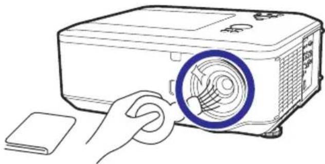
natural_image
Line drawing of a projector with a blue circular button and a hand holding the button, next to a flat sheet (no text or symbols)Cleaning and Replacing the Dust Filters
When the message shown below is displayed, clean or replace the three dust fi Iters and then reset the fi Iter timer (see page 55). You must clean or replace all three dust fi Iters at the same time to synchronize the fi Iter timer.
Clean The Filter.
Cleaning the Dust Filters
Use a vacuum cleaner to clean dust from the exhaust vent and the intake vent (bottom, side and rear).

Info
- The dust filters should be cleaned every 100 hours of use. Clean the filters more often when the projector is used in a dusty or smoky location.
- If you want to clean the air vents during projector operation, ensure you press STANDBY/ON on the projector or on the remote control and put the projector into Standby mode. After the cooling fan has stopped, clean the vents.

natural_image
Technical line drawings of an open projector case with two views showing internal components and close-ups of connectors (no text or symbols present)Replacing the Dust Filters

Info
- If the filters become too dirty to clean effectively, purchase new ones (Front: 9NK3243073701, Side: 9NK3243073801, Rear: 9NK3243073601) from your nearest Sharp Authorized Projector Dealer or Service Center.
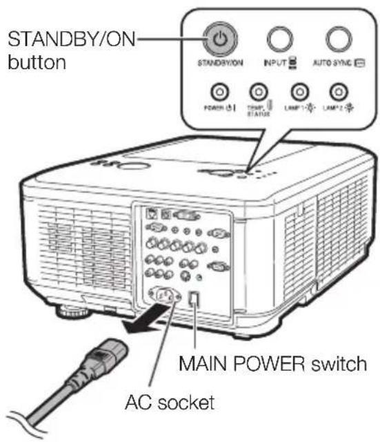
1
Press STANDBY/ON on the projector or on the remote control to put the projector into standby mode.
- Switch the MAIN POWER switch on the projector to "OFF" after the cooling fan stops, and then disconnect the power cord and unplug the power cord from the AC socket.
2 Remove the fi Iter covers.
- Remove the filter covers towards the direction of the arrow.
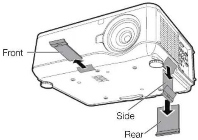
3 Pick the dust fi Iters up and lift them out of all the three fi Iter covers as shown in the fi gures.
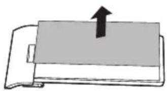
natural_image
Simple line drawing of a mechanical component with an upward arrow, no text or symbols present4 Place replacement dust fi Iters and press them down fi rmly.

natural_image
Simple line drawing of a rectangular object with a downward arrow and small square holes, no text or symbols present.5 Replace the fi Iter covers.
- Insert the filter covers and push them gently as shown in the figure.

Maintenance Indicators
■ The warning lights (POWER indicator, TEMP. (temperature warning)/STATUS indicator and LAMP indicator) on the projector indicate problems inside the projector.
If a problem occurs, either the TEMP. (temperature warning)/STATUS indicator or the LAMP indicator will illuminate red, and the projector will enter Standby mode. After the projector has entered Standby mode, follow the procedures given below.
Top View


POWER

TEMP.

LAMP 1

LAMP2
LAMP (1, 2) indicators
TEMP. (temperature warning)/STATUS indicator
POWER indicator
About the TEMP. (temperature warning)/STATUS indicator
If the temperature inside the projector increases, due to blockage of the air vents, or the setting location, the lamp will turn off, the cooling fan will run and then the projector will enter Standby mode, and then the TEMP. (temperature warning)/STATUS indicator will blink. When you find the TEMP. (temperature warning)/STATUS indicator blinking, be sure to perform the measures described on page 65.
About the LAMP indicator

Change The Lamp.(LAMP1)
- When the remaining lamp life becomes 5% or less, (yellow) and “Change The Lamp.(LAMP1/2)” will be displayed on the screen. When the percentage becomes 0%, it will change to (red), the lamp will automatically turn off and then the projector will automatically enter Standby mode. At this time, the lamp indicator will illuminate in red.
If you try to turn on the projector a fourth time without replacing the lamp, the projector will not turn on.
Indicators on the Projector
| POWER indicator | Red on Normal (Standby) | |
| Green on Normal (Power on) | ||
| Orange blinks Normal (Cooling) | ||
| Green blinks Normal (Warming up) | ||
| LAMP indicator Green on Normal (“Eco + Quiet” is “Off”.) | ||
| TEMP.(temperature warning)/STATUS indicator | Off | Normal |
| Red/Orange blinks | Abnormal. (See page 65.) | |
| Maintenance indicator | Problem Cause | Possible Solution | |||
| Normal Abnormal | |||||
| TEMP.(temperature warning)/STATUS indicator | Off Red | blinks The TEM. (temperature warning)/STATUS indicator blinks in red when the projector is on. | • If the temperature is open. | • Temperature is open. | • Warning)/STATUS indicator blinks in red even when the lamp unit cover are securely installed, contact your nearest Sharp Authorized Projector Dealer or Service Center (see page 76) for advice. |
| Red blinks 2 times (Repeatedly) | The internal temperature is abnormally high. | • Temperatures around the projector are high.• Blocked air intake• Internal circuit failure. | • Use the projector in an area with a temperature of lower than 104°F (+40°C).• Relocate the projector to an area with proper ventilation. (See page 8.) | ||
| Orange blinks | • Cooling fan breakdown• Internal circuit failure• Clogged air intake | • Take the projector to your nearest Sharp Authorized Projector Dealer or Service Center (see page 76) for repair. | |||
| LAMP indicator | Green on (Green blinks when the lamp is warming up.)/Orange on (Eco) | Red blinks | The lamp does not illuminate. | No lamp• Install the lamp unit. | |
| Time to change the lamp. | • Biscaining the lamp becomes 5% or less. | ord from the AC outlet, and then connect it again.• Carefully replace the lamp. (See page 66.)• Take the projector to your nearest Sharp Authorized Projector Dealer or Service Center (see page 76) for repair.• Please exercise care when replacing the lamp.• Securely install the cover. | |||
| Red blinks 2 times (Repeatedly) | The lamp does not illuminate. | • The lamp is shut down abnormally.• Burnt-out lamp• Lamp circuit failure | |||
| Orange blinks (When the lamp is cooling.) | Red on Time | the lamp. | The lamp life is over. | ||
* For information about other types of blinking, contact your nearest Sharp Authorized Projector Dealer or Service Center (see page 76).

Info
- If the TEMP. (temperature warning)/STATUS indicator illuminates, and the projector enters Standby mode, follow the possible solutions above and then wait until the projector has cooled down completely before plugging in the power cord and turning the power back on. (At least 10 minutes.)
- If the power is turned off for a brief moment due to power outage or some other cause while using the projector, and the power supply recovers immediately after that, the LAMP indicator will illuminate in red and the lamp may not be lit. In this case, unplug the power cord from the AC outlet, replace the power cord in the AC outlet and then turn the power on again.
- The cooling fan keeps the internal temperature of the projector constant and this function is controlled automatically. The sound of the cooling fan may change during operation because the fan speed may change and this is not a malfunction.
Regarding the Lamp
Lamp
It is recommended that the lamp (sold separately) be replaced when the remaining lamp life becomes 5% or less, or when you notice a signifi cant deterioration in the picture and color quality. The lamp life (percentage) can be checked with the on-screen display. (See page 55.)
■ Purchase a replacement lamp of type AN-PH80LP from your place of purchase, nearest Sharp Authorized Projector Dealer or Service Center.
IMPORTANT NOTE TO U.S. CUSTOMERS:
The lamp included with this projector is backed by a 90-day parts and labor limited warranty. All service of this projector under warranty, including lamp replacement, must be obtained through a Sharp Authorized Projector Dealer or Service Center. For the name of the nearest Sharp Authorized Projector Dealer or Service Center, please call toll-free: 1-888-GO-SHARP (1-888-467-4277).
Hg LAMP CONTAINS MERCURY For State Lamp Disposal Information
www.lamprecycle.org or 1-800-BE-SHARP
U.S.A ONLY
Caution Concerning the Lamp
This projector utilizes a pressurized mercury lamp. A loud sound may indicate lamp failure. Lamp failure can be attributed to numerous sources such as: excessive shock, improper cooling, surface scratches or deterioration of the lamp due to a lapse of usage time.
The period of time up to failure largely varies depending on the individual lamp and/or the condition and the frequency of use. It is important to note that failure can often result in the bulb cracking.
■ When the lamp replacement indicator and on-screen display icon are illuminated, it is recommended that the lamp be replaced with a new one immediately, even if the lamp appears to be operating normally.
■ Should the lamp break, there is also a possibility that glass particles may spread inside of the projector. In such a case, it is recommended you contact your nearest Sharp Authorized Projector Dealer or Service Center to assure safe operation.
■ Should the lamp break, the glass particles may spread inside the lamp cage or gas contained in the lamp may be vented into the room from the exhaust vent. Because the gas in this lamp includes mercury, ventilate the room well if the lamp breaks and avoid all exposure to the released gas. In case of exposure to the gas, consult a doctor as soon as possible.
Replacing the Lamp

Caution
- Do not remove the lamp unit from the projector right after use. The lamp will be very hot and may cause burns or injury.
- Wait at least one hour after the power cord is disconnected to allow the surface of the lamp unit to fully cool before removing the lamp unit.
■ Carefully change the lamp by following the instructions described in this section.
* If you wish, you may have the lamp replaced at your nearest Sharp Authorized Projector Dealer or Service Center.
* If the new lamp does not light after replacement, take your projector to the nearest Sharp Authorized Projector Dealer or Service Center for repair.
Removing and Installing the Lamp Unit

Info
- Do not touch the glass surface of the lamp unit or the inside of the projector.
- To avoid injury to yourself and damage to the lamp, make sure you carefully follow the steps below.
- Do not loosen other screws except for the lamp unit cover and lamp unit.

Warning!
- Do not remove the lamp unit from the projector right after use. The lamp and parts around the lamp will be very hot and may cause burns or injury.
Optional accessory

Lamp unit AN-PH80LP
1
Press STANDBY/ON on the projector or on the remote control to put the projector into Standby mode.
2
Switch the MAIN POWER switch on the projector to "OFF" and then disconnect the power cord.
- Unplug the power cord from the AC socket.
- Leave the lamp until it has fully cooled down (about 1 hour).
STANDBY/ON button

3
Remove the lamp unit cover.
- Loosen the user service screw (①) that secures the lamp unit cover. Remove the lamp unit cover (②).

User service screw (for lamp unit cover)
4
Remove the lamp unit.
- Loosen the securing screws (two for each lamp) from the lamp unit. Hold the lamp unit by the handle and pull it in the direction of the arrow. At this time, keep the lamp unit horizontal and do not tilt it.

natural_image
Diagram of a mechanical assembly with two blocks and a tool, no visible text or symbols
natural_image
Diagram of two hands assembling or adjusting electronic components with arrows indicating assembly (no text or symbols present)Regarding the Lamp (Continued)
5 Insert the new lamp unit.
- Press the lamp unit firmly into the lamp unit compartment. Fasten the securing screw.
6 Replace the lamp unit cover.
- Align the lamp unit cover and slide it to close (①). Then tighten the user service screw (②) to secure the lamp unit cover.

Info
- If the lamp unit and lamp unit cover are not correctly installed, the power will not turn on, even if the power cord is connected to the projector.
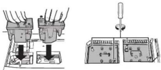
natural_image
Technical line drawing showing two mechanical assembly steps: one with a tool inserted into a housing, the other with a screwdriver inserted into a control panel (no text or symbols present)
natural_image
Illustration of a portable electronic device with labeled ports and an arrow indicating direction (no text or symbols present)Resetting the Lamp Timer
Reset the lamp timer after replacing the lamp.

Info
- Make sure to reset the lamp timer only when replacing the lamp. If you reset the lamp timer and continue to use the same lamp, this may cause the lamp to become damaged or explode.
- You can reset the lamp timer only when "STANDBY mode" is set to "Standard".
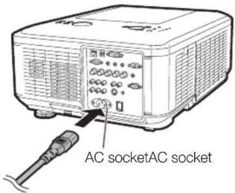
1 Connect the power cord and switch the MAIN POWER switch on the projector to "ON".
- Plug the power cord into the AC socket of the projector.
2 Reset the lamp timer.
- The projector enters Standby mode when you reset the lamp timer.
For Lamp 1
- When you reset the timer, press MENU → ENTER → ENTER → MENU → ◀ → STANDBY/ON on the projector.
- "LAMP1 0000H" is displayed, indicating that the lamp timer is reset.
For Lamp 2
- When you reset the timer, press MENU → ENTER → ENTER → MENU → ▶ → STANDBY/ON on the projector.
- "LAMP2 0000H" is displayed, indicating that the lamp timer is reset.

Replacing the Color Wheel
The projector is equipped with a four-segment color wheel. You can replace it with a six-segment color wheel (sold separately). The replacement procedure described below also applies when you put the four-segment color wheel back in the place of the six-segment one.

Warning!
- Do not remove the color wheel from the projector right after use. The lamp and parts around the lamp will be very hot and may cause burns or injury.
1
Press STANDBY/ON on the projector or on the remote control to put the projector into Standby mode.
2
Switch the MAIN POWER switch on the projector to "OFF" and then disconnect the power cord.
- Unplug the power cord from the AC socket.
- Leave the lamp until it has fully cooled down (about 1 hour).

3
Remove the lamp unit cover.
- Loosen the user service screw (①) that secures the lamp unit cover. Remove the lamp unit cover (②).
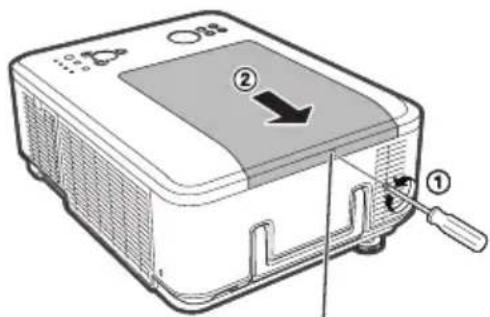
User service screw (for lamp unit cover)
Replacing the Color Wheel (Continued)
4 Loosen the 4 retaining screws from the four-segment color wheel.
5 Hold the color wheel and pull it in the direction of the arrow.
Caution
The module contains components that can be damaged or destroyed by electrostatic discharge. Please pick the module with the handle.
6 Insert the six-segment color wheel, and tighten the 4 retaining screws.
7 Replace the lamp unit cover.
- Align the lamp unit cover and slide it to close (①). Then tighten the user service screw (②) to secure the lamp unit cover.

Info
Storing the Unused Color Wheel:
Use the zipper bag in which the six-segment color wheel was packaged to store the unused color wheel. This bag prevents dust and dirt from collecting on the color wheel.
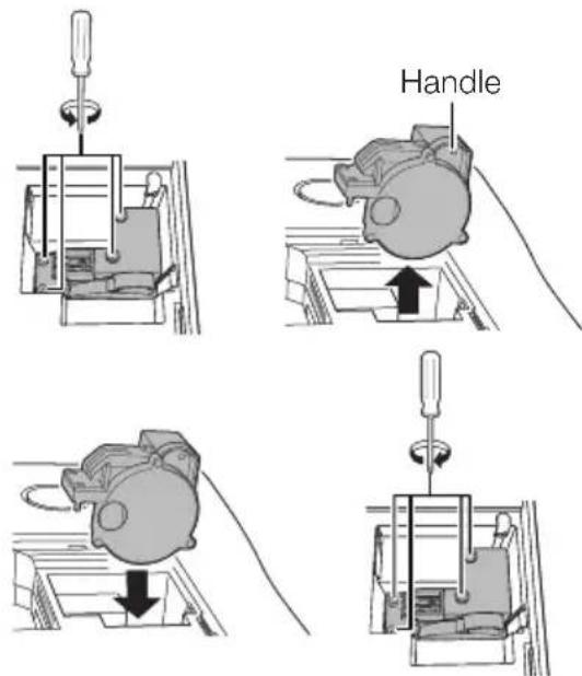

Compatibility Chart
Computer
- Multiple signal support Horizontal Frequency: 15, 31-90 kHz, Vertical Frequency: 50-85 Hz,
Pixel Clock: 12-165 MHz Sync signal: Compatible with TTL level • Compatible with sync on green signal
| PC/MAC Mode Resolution | Horizontal Frequency (kHz) | Vertical Frequency (Hz) | Analog Support | Digital Support | Display | |||
| XG-PH80W-N XG-PH80X-N | ||||||||
| PC | VGA 640 × 480 | 31.5 | 60 | √ | √ | Upscale | Upscale | |
| 37.9 | 72 | √ | √ | |||||
| 37.5 | 75 | √ | √ | |||||
| 43.3 | 85 | √ | ||||||
| SVGA 800 × 600 | 35.2 | 56 | √ | √ | ||||
| 37.9 | 60 | √ | √ | |||||
| 48.1 | 72 | √ | √ | |||||
| 46.9 | 75 | √ | √ | |||||
| 53.7 | 85 | √ | ||||||
| XGA 1024 × 768 | 48.4 | 60 | √ | √ | TRUE | |||
| 56.5 | 70 | √ | √ | |||||
| 60.0 | 75 | √ | √ | |||||
| 68.7 | 85 | √ | ||||||
| WXGA | 1280 × 720 45.0 | 60 | √ | √ | TRUE | Intelligent Compression | ||
| 1280 × 768 47.8 | 60 | √ | √ | |||||
| 1280 × 800 | 49.7 | 60 | √ | √ | ||||
| 62.8 | 75 | √ | ||||||
| 1360 × 768 47.7 | 60 | √ | Intelligent Compression | |||||
| 1366 × 768 47.7 | 60 | √ | ||||||
| WXGA+ 1440 × 900 55.9 60 | √ | |||||||
| SXGA | 1152 × 864 67.5 | 75 | √ | |||||
| 1280 × 960 60.0 | 60 | √ | √ | |||||
| 1280 × 1024 | 64.0 | 60 | √ | √ | ||||
| 80.0 | 75 | √ | √ | |||||
| SXGA+ 1400 × 1050 65.3 60 | √ | √ | ||||||
| WSXGA+ 1680 × 1050 65.3 60 | √ | |||||||
| UXGA | 1600 × 1200 75.0 | 60 | √ | |||||
| MAC 13" | VGA 640 × 480 34.9 67 | √ | Upscale | Upscale | ||||
| MAC 16" | SVGA 832 × 624 49.7 75 | √ | ||||||
| MAC 19" | XGA 1024 × 768 60.2 75 | √ | TRUE | |||||
| MAC 21" | SXGA | 1152 × 870 68.7 | 75 | √ | Intelligent Compression | Intelligent Compression | ||

Note
- Optimum image quality will be achieved by matching your computer's output resolution to the resolution that corresponds to "TRUE" in the "Display" column shown above.
- When “Screen resolution” of the computer is different from the resolution displayed on the projected image, follow the procedures shown below.
- Make the appropriate adjustments for "Resolution" in "SIG-ADJ".
- Depending on the computer you are using, the output signal may not be faithful to the "Screen resolution" adjustment. Check the settings of the computer's signal output. If the settings cannot be changed, it is recommended that the resolution be set to the one that corresponds to "TRUE" in the "Display" column.
Compatibility Chart (Continued)
3D Supported Signals
| Signal Horizontal Frequency (kHz) Vertical Frequency (Hz) | Analog Support | Digital Support | |||
| SVGA 800 | ×600 | 37.9 60 | √ | √ | |
| 77.1 120 | √ | √ | |||
| XGA 1024 | ×768 | 48.4 60 | √ | √ | |
| 98.6 120 | √ | √ | |||
| WXGA | 1280 ×800 | 49.7 60 | √ | √ | |
| 101.6 120* | 1 | √ | √ | ||
| 1280 ×720 | 45.0 60 | √ | √ | ||
| 92.6 120 | √ | √ | |||
*1 Reduced Blanking

Note
- Your computer graphics card must be able to display 3D stereoscopic signals. Please check with your computer/graphic card specifications or call your computer manufacturer to ensure this capability.
DTV
| Signal | Horizontal Frequency (kHz) | Vertical Frequency (Hz) | Analog Support | Digital Support | Signal | Horizontal Frequency (kHz) | Vertical Frequency (Hz) | Analog Support | Digital Support |
| 480I | 15.7 60 | √ | 1080I | 28.1 50 | √ | √ | |||
| 480P | 31.5 | 60 | √ | √ | 1080I | 33.8 | 60 | √ | √ |
| 576I | 15.6 50 | √ | 1080P | 56.3 | 50 | √ | √ | ||
| 576P | 31.3 | 50 | √ | √ | 1080P | 67.5 | 60 | √ | √ |
| 720P | 37.5 50 | √ | √ | ||||||
| 720P | 45.0 60 | √ | √ | ||||||
Troubleshooting
| ProblemCheckPage | ||
 No picture and no sound or projector does not start. No picture and no sound or projector does not start. | Projector power cord is not plugged into the wall outlet.● | 27 |
| Power to the external connected devices is off.●- | ||
| The selected Input mode is wrong.● | 33 | |
| The AV Mute function is working.●33 | ||
| Cables are incorrectly connected to the projector.●21-25 | ||
| Remote control battery has run out.●16 | ||
| External output has not been set when connecting notebook computer.When the connected DVI digital equipment is turned on before the "DVI-D" input mode is selected on the projector, the image may not be projected properly or may not be displayed at all. Ensure that the appropriate input mode has been selected and set the input signal type on the projector before you turn on the connected equipment. | 21 | |
| The lamp unit cover is not installed correctly. | 67, 68 | |
 Sound is heard but no picture appears (or picture is dark). Sound is heard but no picture appears (or picture is dark). | Cables are incorrectly connected to the projector.● | 21-25 |
| “Bright” is set to minimum position.●44 | ||
| Depending on the computer you are using, an image may not be projected unless the signal output setting of the computer is switched to the external output. Refer to the computer's operation manual for how to switch its signal output settings.Is “On” selected in “DLP® LinkTM”? | -58 | |
| Dark or bluish image | Check that “Wall Color” is configured correctly.● | 50 |
 Color is faded or poor. Color is faded or poor. | Image adjustments are incorrectly set.● | 44 |
| (S-VIDEO, VIDEO Input only)Video input system is incorrectly set.(COMPUTER/COMPONENT1, 2, COMPONENT, DVI Input only)Input signal type (RGB/Component) is incorrectly set. | 4744 | |
 Picture is blurred; noise appears. Picture is blurred; noise appears. | Adjust the focus. | 31 |
| The projection distance exceeds the focus range.When an optional lens is attached, refer to the operation manual of the lens. | - | |
| There is fog on the lens. If the projector is carried from a cold room into a warm room, or if it is suddenly heated, condensation may form on the surface of the lens and the image will become blurred. Set up the projector at least one hour before it is to be used. If condensation should form, remove the power cord from the wall outlet and wait for it to clear. | - | |
| (Computer Input only)Perform “SIG-ADJ” Adjustments (“Clock” and “Phase” Adjustment)Turn off the LCD display of the notebook computer.Noise may appear depending on the computer. | 46- | |
 Picture appears but no sound is heard. Picture appears but no sound is heard. | Cables are incorrectly connected to the projector.● | 21-25 |
| Volume is set to minimum.When the projector is connected to an external device and the volume is set to minimum, the sound is not output even if you turn up the volume of the external device. | 33 | |
| “Speaker” is set to “Off”.The AV Mute function is working. | 5333 | |
Troubleshooting (Continued)
| ProblemCheckPage | ||
| Data image is not centered. | Make the necessary adjustments of each item in the “SIG-ADJ” menu.● | 46 |
| ·Depending on the computer you are using, the output resolution signal may be different from the one you have set. For details, refer to the operation manual of the computer. | - | |
| An unusual sound is occasionally heard from the cabinet. | ·If the picture is normal, the sound is due to cabinet shrinkage caused by room temperature changes. This will not affect operation or performance. | - |
| Maintenance indicator on the projector illuminates or blinks in red. | See “Maintenance Indicators”.● | 64 |
| Picture is green on COMPUTER/ COMPONENT1, 2 (Component). | Change the input signal type setting.● | 44 |
| Picture is pink (no green) on COMPUTER/ COMPONENT1, 2 or DVI (RGB). | ||
| Picture is too bright and whitish. | Image adjustments are incorrectly set.● | 44 |
| The cooling fan becomes noisy. | ·When temperature inside the projector increases, the cooling fan runs faster. | 8, 9, 64, 65 |
| The lamp does not light up even after the projector turns on. | ·The LAMP indicator is illuminating in red. Replace the lamp. | 64, 67, 68 |
| The lamp suddenly turns off during projection. | ||
| The image sometimes flickers. | ·Cables are incorrectly connected to the projector or the connected equipment works improperly.·If this happens frequently, replace the lamp. | 21-2567 |
| The lamp needs much time to turn on. | ·The lamp will eventually need to be changed. While the remaining lamp life draws to a close, replace the lamp. | 67 |
| Picture is dark. | ||
| The remote control cannot be used. | ·Operate the remote control while pointing it at the projector's remote control sensor.·The remote control may be too far away from the projector.·If direct sunlight or a strong fluorescent lamp is shining on the projector's remote control sensor, place the projector where it will not be affected by strong light. | 16 |
| ·TBe batteries may be depleted or inserted incorrectly. Make sure the batteries are inserted correctly or insert new ones. | ||
| 3D images fl icker when watching in a room. | Images may appear to fl icker when fl uorescent light or ambient light enters your vision.Turn off the lights.Block any ambient light. | - |
| Ghosting (a double image) occurs without the image appearing in 3D. | Check that you are using 3D LCD shutter glasses that support the DLP® LinkTM system.Be sure to use 3D LCD shutter glasses that support the DLP® LinkTM system. | - |
| Check that the shutters on the 3D LCD shutter glasses are working properly.Turn the 3D LCD shutter glasses off and then on again.Check the batteries of the 3D LCD shutter glasses.Check that the 3D LCD shutter glasses are set to 3D viewing mode. Some 3D LCD shutter glasses are equipped with a special viewing mode (such as “dual view mode”) in addition to the normal 3D viewing mode. See the operation manual of your 3D LCD shutter glasses. | - | |
| Check the settings of the projector.Turn the DLP® LinkTM function “On”.Use “DLP® LinkTM Invert” to change the setting. | - | |
| Check whether a signal that is not supported is being input.Confi gure your 3D application at the correct resolution and refresh rate.Make sure you are running your 3D application in resolutions that support 3D. To support 3D, your 3D application must be confi gured to run at the correct settings for this projector.For details on the supported signals, see “3D Supported Signals” of the Compatibility Chart. | 72 | |
| If the projector is connected to a computer for 3D image playback, check that a stereoscopically-enabled application is being used.Use the applicable software.Set the applicable software to the fi eld sequential format. | - | |
| Check that there are no obstructions between the screen and the 3D LCD shutter glasses.Remove any obstructions.Any obstructions may cause the glasses not to function properly causing the lenses to fl icker or turn off. Do not place your hand or other objects in front of the 3D control signal sensor on the glasses. | - | |
| Check whether there is a source of high intensity lighting nearby.Block the light or turn it off.High intensity lighting can interfere with communication between the 3D LCD shutter glasses and the screen resulting in some fl icker. | - | |
| Check whether two or more projectors are projecting 3D images at the same time.Use only one projector at a time. | - | |
This unit is equipped with a microprocessor. Its performance could be adversely affected by incorrect operation or interference. If this should happen, unplug the Unit and plug it in again after more than 5 minutes.
For SHARP Assistance
If you encounter any problems during setup or operation of this projector, first refer to the “Troubleshooting” section on pages 73 to 75. If this operation manual does not answer your question, please contact the SHARP Service departments listed below.
| U.S.A. | Sharp Electronics1-888-GO-SHARPlcdsupport@sharpsec.comhttp://www.sharpusa.com | Corporation | SHARP Electronics Benelux BV0900-SHARPCE (0900-7427723)Nederland9900-0159 Belgiumhttp://www.sharp.nlhttp://www.sharp.behttp://www.sharp.lu |
| Canada Sharp Electronics of Canada Ltd.(905) 568-7140http://www.sharp.ca | |||
| Mexico | Sharp ElectronicsMexico Branch(525) 716-9000http://www.sharp.com.mx | Australia Corporation | Sharp Corporation of Australia Pty.Ltd.1300-135-022http://www.sharp.net.au |
| Latin America | Sharp Electronics Corp. Latin American Group(305) 264-2277www.servicio@sharpsec.comhttp://www.sharpla.com | New Zealand Phone: (09) 573-0111Fax: (09) 573-0112 | Sharp Corporation of New Zealand65-226-6556ckng@srs.global.sharp.co.jphttp://www.sharp.com.sg |
| Germany Sharp Electronics (Europe) GMBH01805-234675http://www.sharp.de | Singapore | Sharp-Roxy Sales (S) Pte. Ltd.65-226-6556ckng@srs.global.sharp.co.jphttp://www.sharp.com.sg | |
| U.K. Sharp Electronics (U.K.) Ltd.08705 274277http://www.sharp.co.uk/customersupport | Hong Kong | Sharp-Roxy (HK) Ltd.(852) 2410-2623dcmktg@srh.global.sharp.co.jphttp://www.sharp.com.hk | |
| Italy Sharp Electronics (Italy) S.P.A.(39) 02-89595-1http://www.sharp.it | Taiwan | Sharp Corporation (Taiwan)0800-025111http://www.sharp-scot.com.tw | |
| France01 49 90 35 40 | Sharp Electronicshotlineced@sef.sharp-eu.comhttp://www.sharp.fr | France Malaysia | Sharp-Roxy Sales & Service Co.(60) 3-5125678 |
| Spain Sharp Electronica Espana, S.A.93 5819700sharplcd@sees.sharp-eu.comhttp://www.sharp.es | U.A.E. | Sharp Middle East Fze971-4-81-5311helpdesk@smef.global.sharp.co.jp | |
| Switzerland Sharp Electronics (Schweiz) AG0041 1 846 63 11cattaneo@sez.sharp-eu.comhttp://www.sharp.ch | Thailand | Sharp Thebnakorn Co. Ltd.02-236-0170svc@stcl.global.sharp.co.jphttp://www.sharp-th.com | |
| Sweden Sharp Electronics ( Nordic ) AB(46) 8 6343600vision.support@sen.sharp-eu.comhttp://www.sharp.se | Korea | Sharp Electronics Incorporated of Korea(82) 2-3660-2002lcd@sharp-korea.co.krhttp://www.sharpkorea.co.kr | |
| Austria Sharp Electronics (Europe) GMBHBranch Office Austria0043 1 727 19 123pogats@sea.sharp-eu.comhttp://www.sharp.at | India Sharp Business Systems (India)Limited(91) 11- 6431313service@sharp-oa.com | ||
Specifications
| Model XG-PH80W-N XG-PH80X-N | |||
| Display devices 0.65" DLP | ® Chip 0.7" DLP | ® Chip | |
| Resolution WXGA (1280 × 800) XGA (1024 × 768) | |||
| Optional Lens(Standard)(AN-PH818EZ) | F number F 1.7 - 1.9 | ||
| Zoom Power, ×1.3 (f = 26.0 - 34.0 mm) | |||
| Focus Power | |||
| Lens shift Power (V: +50% / H: ±10%) | |||
| Input terminals DVI-D (Compatible with HDCP) ×1 | |||
| Computer/Component (5BNC) | ×1 | ||
| Computer/Component(D-sub 15 pin) | ×1 | ||
| Component (RCA) | ×1 (Y/Pb (Cb)/Pr (Cr)) | ||
| S-Video (mini DIN 4 pin) | ×1 | ||
| Video (RCA) | ×1 | ||
| Audio (ø3.5 mm stereo minijack) | ×3 | ||
| Audio (RCA) | ×2 (L/R) | ||
| Outputterminals | Computer/Component(D-sub 15 pin) | ×1 | |
| Audio (ø3.5 mm stereo minijack) | ×1 (variable audio output) | ||
| TRIGGER | ×1 (DC 12 V output) | ||
| Control andcommunicationterminals | LAN (RJ-45) | ×1 | |
| USB (Type B) | ×1 | ||
| RS-232C (D-sub 9 pin) | ×1 | ||
| Speaker | 3 W × 2 (Stereo) | ||
| Projection lamp 280 W × 2 lamps | |||
| Rated voltage | AC 100 - 240 V | ||
| Rated frequency | 50/60 Hz | ||
| Input current | 7.3 A | ||
| Power consumption (STANDBY Mode: Standard/Eco) | 715 W (20.3 W/0.28 W) with AC 100 V675 W (21.3 W/0.41 W) with AC 240 V | ||
| Operation temperature | 41°F to 104°F (+5°C to +40°C) | ||
| Cabinet | Plastic | ||
| Dimensions (main body only) [W × H × D] | 19 57/64" × 7 41/64" × 15 11/64"(505 × 194 × 385 mm) | ||
| Weight (approx.) | 36.4 lbs. (16.5 kg) | ||
As a part of policy of continuous improvement, SHARP reserves the right to make design and specification changes for product improvement without prior notice. The performance specification figures indicated are nominal values of production units. There may be some deviations from these values in individual units.
This SHARP projector uses a DLP ^® chip. This very sophisticated panel contains 1,024,000 (XG-PH80W-N) or 786,432 (XG-PH80X-N) pixels (micromirrors). As with any high technology electronic equipment such as large screen TVs, video systems and video cameras, there are certain acceptable tolerances that the equipment must conform to.
This unit has some inactive pixels within acceptable tolerances which may result in inactive dots on the picture screen. This will not affect the picture quality or the life expectancy of the unit.
Dimensions
Units: inches (mm)

Index
4:3....35
16:9....34
3D MODE 54
3D MODE button 15
Accessories 11
AC socket 27
Adjustment buttons 41, 42
Adjustment foot 30
All Reset 55
Apply 54
Aspect ratio 34
AUDIO terminals 21-23
AUDIO output terminal 23
Auto Power Off 52
Auto Restart 52
Auto Search 52
Auto Sync (Auto Sync adjustment) 36, 46
AUTO SYNC button 36
AV MUTE button 33
Background 49
Batteries 16
Blue 44
Bright 44
Bright Boost 44
Clock 46
Closed Caption 48
CLR Temp (Color Temperature) 44
C.M.S. 45
Color 44
COMPONENT terminal 22
COMPUTER/COMPONENT1, 2 input terminals …… 21-23
Contrast 44
DHCP Client 54
DLP ^® Link ^TM 59
DLP ^® Link ^TM Invert 59
DNR 45
DNS 54
DVI-D terminal 21, 22
Dynamic Black 45
Eco+Quiet 52
ENTER button 33
Exhaust vent 8,62
Fan Mode 53
Film Mode 45
Filter Message 54
Filter Timer Reset 55
FOCUS buttons 31
FREEZE button 36
Full 34
H-Pos 46
Image Capture 51
Image Resizing 32,50
Information 55
INPUT modes 33
Intake vent 8,62
IP Address 54
Kensington Security Standard connector 14
KEYBOARD CURSOR buttons 37
Keypad lock 51
Keystone Correction 32,50
Lamp 66
LAMP indicator 64
Lamp Mode 53
Lamp Timer (Life) 55
Lamp unit 67
Language (on-screen display language) 49
LAN/RS232C 54
LAN terminal 25
LENS SHIFT button 30
Link 54
MENU button 41
MONITOR OUT terminal 23
Native 35
Network 54
Normal 34
Optional accessories 11
Overscan 47
PAGE DOWN button 37
PAGE UP button 37
Password 51
PDF....10
Phase 46
Picture Adjustment 43
Picture Mode 43
Power cord 27
POWER indicator....64
PRJ-ADJ 52
PRJ Mode 20,49
Red 44
Remote control 15
Remote control sensor 16
Replacing the lamp....66, 67
Resize 34,49
Resolution 46
RETURN button 41
RGB cable 21
RS-232C terminal 24
SCR-ADJ 49
Security Lock 51
Sharp 44
SIG-ADJ 46
Signal Info 55
Signal Type 44
Speaker 53
STANDBY Audio Out 53
STANDBY Mode 53
STANDBY/ON button 28
Supplied accessories 11
S-VIDEO terminal 23
TEMP. (temperature warning)/STATUS indicator ……64
Tint 44
TRIGGER terminal 14
USB terminal 37
Video menu 47
Video Setup 48
Video System 47
VIDEO terminal 23
VOL (Volume) buttons 33
V-Pos 46
Wall Color 50
ZOOM buttons 31
SHARP®
SHARP CORPORATION
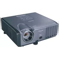
- IMPORTANT
- Model No.:
- Serial No.:
- SPECIAL NOTE FOR USERS IN THE U.K.
- DANGER:
- WARNING:
- IMPORTANT:
- Introduction
- ENGLISH
- WARRANTY
- CONSUMER PRODUCT SAFETY ACT
- INFORMATION
- PRODUCT DISPOSAL
- Caution Concerning Lamp Replacement
- Caution
- How to Read this Operation Manual
- For Future Reference
- Contents
- Preparing
- Easy Start
- Setup
- Connections
- Using
- Basic Operation
- Useful Features
- Adjusting the Projector Function
- Viewing Stereoscopic 3D Images .....56
- Reference
- Appendix
- IMPORTANT SAFEGUARDS
- CAUTION: Please read all of these instructions before you operate this product and save these instructions for later use.
- Read Instructions
- Retain Instructions
- Heed Warnings
- Follow Instructions
- Cleaning
- Attachments
- Water and Moisture
- Accessories
- Transportation
- Ventilation
- Power Sources
- Grounding or Polarization
- Power-Cord Protection
- Lightning
- Overloading
- Object and Liquid Entry
- Servicing
- Damage Requiring Service
- Replacement Parts
- Safety Check
- Wall or Ceiling Mounting
- Heat
- Observe the following safeguards when setting up your projector.
- Caution concerning the lamp unit
- Caution concerning the setup of the projector
- Rest your eyes occasionally.
- Do not set up the projector in places exposed to direct sunlight or bright light.
- Caution regarding placing of the projector
- When using the projector in high-altitude areas such as mountains (at altitudes of approximately 1,200 meters (4,000 feet) or more)
- Warning about placing the projector in a high position
- Do not subject the projector to hard impact and/or vibration.
- Avoid locations with extremes of temperature.
- Do not block the exhaust and intake vents.
- Caution regarding usage of the projector
- Other connected equipment
- Using the projector in other countries
- Temperature monitor function
- Info
- Optional lens installation
- Closed Caption uses Bitstream Vera fonts
- How to Access the PDF Operation Manuals
- Accessing the PDF Manuals
- For Windows®:
- When you want to view the SETUP MANUAL
- For Macintosh®:
- Note
- SETUP MANUAL
- Accessories
- Supplied accessories
- Optional accessories
- Accessories (Continued)
- Throw Distance
- XG-PH80W-N
- XG-PH80X-N
- Part Names and Functions
- Top View
- Front View
- Part Names and Functions (Continued)
- Side View (Terminals)
- Using the Kensington Lock
- STANDBY/ON button28
- KEYBOARD CURSOR (UP/DOWN/LEFT/RIGHT/ENTER) buttons 37
- PAGE UP button 37
- Adjustment buttons (▲/▼/◄/►) 30, 41
- ZOOM buttons31
- MENU button41
- AUTO SYNC butto36
- LENS SHIFT button 30
- 3D MODE button 59
- INPUT button 33
- PAGE DOWN button37
- (ENTER) button 33
- FOCUS buttons 31
- RETURN button41
- VOL +/- (Volume) buttons 33
- AV MUTE button 33
- FREEZE button36
- Inserting the Batteries
- Incorrect use of the batteries may cause them to leak or explode. Please follow the precautions below
- Usable Range
- When using the remote control
- Setup and Projection
- Turn the projector on
- Easy Start (Continued)
- Adjust the angle
- Adjust the focus and the zoom
- Correcting the image distortion due to the projection angle
- Select the Input mode
- Turn the computer on
- Turn the power off
- Setting Up the Projector
- Video Setup
- Standard Setup (Front Projection)
- Indication of the Projection Image Size and Projection Distance
- Setting Up the Projector (Continued)
- Projection (PRJ) Mode
- ■ Ceiling-Mount Setup
- Connecting the Projector to Other Equipment
- Connecting the Projector to Other Equipment (Continued)
- Controlling the Projector by a Computer
- When connecting to a computer using an RS-232C serial control cable
- When connecting to the LAN terminal using a LAN cable
- Attaching the Optional Lens
- 1
- 2
- 3
- 4
- 5
- Using the Anti-Theft Screw
- Connecting the Power Cord
- Turning the Projector On/Off
- Turning the Projector On
- Turning the Power Off (Putting the Projector into Standby Mode)
- Enter STANDBY Mode?
- Direct Power Off function:
- Shifting the Lens
- Adjustable range
- Image Projection (Continued)
- Using the Adjustment Feet
- Rotate the adjustment feet to adjust the projected angle.
- [Non-Text]
- Warning!
- Adjusting the Focus
- Adjusting the Projected Image Size
- Correcting Trapezoidal Distortion
- Switching the Input Mode
- Adjusting the Volume
- Displaying the Black Screen and Turning Off the Sound Temporarily
- Resize Mode
- About Copyrights
- Operating with the Remote Control
- Auto Sync (Auto Sync Adjustment)
- Freezing a Moving Image
- Press FREEZE.
- Press FREEZE again to return to the moving image from the currently connected device.
- Using the Remote Control to Operate the Computer
- Connecting with a USB cable
- The computer can be operated in the following way after it is connected.
- ■ When moving the cursor
- ■ When using [Enter]
- ■ When using [Page Up] or [Page Down]
- Menu Items
- Using the Menu Screen
- Menu Selections (Adjustments)
- Using the Menu Screen (Continued)
- Press ▲ or ▼ and select "Bright" to adjust.
- Press ◀ or ▶ to adjust the item selected.
- Press MENU.
- Picture Adjustment ("Picture" Menu)
- ① Selecting the Picture Mode
- Picture Adjustment (“Picture” Menu) (Continued)
- ③ Using the Ex. Setting
- ④ Signal Type Setting
- ⑥ Adjusting the Red/Blue
- ⑦ Adjusting the Colors
- ⑧ Selecting the Film Mode
- ⑨ Reducing Image Noise (DNR)
- ⑩ Setting the Dynamic Black
- Signal Adjustment ("SIG-ADJ" Menu)
- ① Adjusting the Computer Image
- ② Setting the Resolution
- ③ Auto Sync (Auto Sync Adjustment)
- Video Adjustment ("Video" Menu)
- ①Setting the Overscan
- ② Setting the Video System
- Video Adjustment (“Video” Menu) (Continued)
- Setting the Video Setup
- Closed Caption
- Adjusting the Projected Image ("SCR-ADJ" Menu)
- ① Selecting the On-screen Display Language
- ② Selecting the Background Image
- ③ Reversing/Inverting Projected Images
- ④ Setting the Resize Mode
- Adjusting the Projected Image ("SCR-ADJ" Menu) (Continued)
- ⑤ Keystone Correction
- Select "Keystone" on the "SCR-ADJ" menu and adjust with the slide bar.
- ⑥ Image Resizing
- Select "Image Resizing" on the "SCR-ADJ" menu and adjust with the slide bar.
- ⑦ Selecting the Wall Color
- ⑧ Using the Ex. Setting
- ⑨ Security Lock Function
- ■ Setting a Password
- ■ Canceling a Password
- ⑩ Keypad Lock Function
- ■ Taking the Keypad Lock Off
- ⑪ Image Capture
- Adjusting the Projector Function ("PRJ-ADJ" Men u)
- ① Detecting the Input Signals Automatically
- ② Auto Power Off Function
- ③ Auto Restart Function
- ④ Eco+Quiet
- ⑤ Setting the Lamp Mode
- ⑥ Setting the Audio
- ⑦ Using the Ex. Setting
- ⑧ Fan Mode Setting
- ⑨ STANDBY Mode
- ⑩ STANDBY Audio Out
- Adjusting the Projector Function (“PRJ-ADJ” Menu) (Continued)
- ⑪ Filter Message
- 3D MODE
- Setting the LAN/RS232C
- ⑭ Setting the Network
- DHCP Client
- ⑮ Returning to the Default Settings
- All Reset
- ■ Filter Timer Reset
- Information
- Precautions on Viewing Stereoscopic 3D Images
- WARNING
- ■ Epilepsy
- IF YOU OR ANY MEMBER OF YOUR FAMILY HAS A HISTORY OF EPILEPSY
- SOME LIGHT PATTERNS MAY INDUCE SEIZURES IN PERSONS WITH NO PRIOR HISTORY OF EPILEPSY
- Information on the 3D Projection Function
- Using 3D Viewing Mode
- Projecting 3D images
- Ending 3D projection
- Viewing Stereoscopic 3D Images (Continued)
- Maintenance
- Cleaning the projector
- Cleaning the lens
- Cleaning and Replacing the Dust Filters
- Cleaning the Dust Filters
- Replacing the Dust Filters
- Remove the fi Iter covers.
- Replace the fi Iter covers.
- Maintenance Indicators
- About the TEMP. (temperature warning)/STATUS indicator
- About the LAMP indicator
- Change The Lamp.(LAMP1)
- Regarding the Lamp
- Lamp
- IMPORTANT NOTE TO U.S. CUSTOMERS:
- Caution Concerning the Lamp
- Replacing the Lamp
- Removing and Installing the Lamp Unit
- Optional accessory
- Regarding the Lamp (Continued)
- Insert the new lamp unit.
- Replace the lamp unit cover.
- Resetting the Lamp Timer
- Connect the power cord and switch the MAIN POWER switch on the projector to "ON".
- Reset the lamp timer.
- For Lamp 1
- For Lamp 2
- Replacing the Color Wheel
- Replacing the Color Wheel (Continued)
- Storing the Unused Color Wheel:
- Compatibility Chart
- Computer
- Compatibility Chart (Continued)
- Troubleshooting
- Troubleshooting (Continued)
- For SHARP Assistance
- Specifications
- Dimensions
- Index
- SHARP®
Brand : SHARP
Model : XG-PH80WN
Category : Video projector