Tube Architectural DS-WS06-F27A-BK - Lighting WAC Lighting - Free user manual and instructions
Find the device manual for free Tube Architectural DS-WS06-F27A-BK WAC Lighting in PDF.

User questions about Tube Architectural DS-WS06-F27A-BK WAC Lighting
0 question about this device. Answer the ones you know or ask your own.
Ask a new question about this device
Download the instructions for your Lighting in PDF format for free! Find your manual Tube Architectural DS-WS06-F27A-BK - WAC Lighting and take your electronic device back in hand. On this page are published all the documents necessary for the use of your device. Tube Architectural DS-WS06-F27A-BK by WAC Lighting.
USER MANUAL Tube Architectural DS-WS06-F27A-BK WAC Lighting
IMPORTANT: NEVER attempt any work without shutting off the electricity.
- Read all instructions before installing.
- System is intended for installation by a qualified electrician in accordance with the National Electrical Code and local regulations.
- Go to the main fuse box, or circuit breaker. Place the main power switch in the "OFF" position and unscrew the fuse(s) or switch "OFF" the circuit breaker switch(es) that control the power to the fixture or room that you are working on.
- Place the wall switch in the "OFF" position.
CAUTION
- All parts must be used as indicated in these instructions. Do not substitute any parts, leave parts out, or use any parts that are worn out or broken. Failure to follow this instruction could invalidate the ETL/CETL listing of this fixture. CAUTION When handling the fixture, do not apply pressure to the LEDs. Hold the fixture by the base only.
AVERTISSEMENT
Wire Connector Junction Box Screw Gasket
waclighting.com
Phone (800) 526.2588
Fax (800) 526.2585
Headquarters/Eastern Distribution Center
44 Harbor Park Drive
Port Washington, NY 11050
Central Distribution Center
1600 Distribution Ct
Lithia Springs, GA 30122
Western Distribution Center
1750 Archibald Avenue
Ontario, CA 91760
OVERVIEW
It is surface mount down light, included ceiling mount, pendant mount, single direction wall wash and up-down direction wall wash. Check catalog for various mount type, size, beam angle and color choices.
FIXTURE INSTALLATION
- Carefully unpack your new fixture and lay out all the parts on a clear area. Be carefully not to lose any small parts necessary for installation. (See FIG.1)
- Remove the screw holding mounting plate to fixture, and remove mounting plate from fixture. (See FIG.2)
- Secure mounting plate to the junction box in wall provided by others. (See FIG.2)
- Pull power supply wires out of junction box through mounting plate. Connect black fixture wire to hot wire, white fixture wire to neutral wire and green fixture wire to ground. This fixture offers 0-10V dimming capability. To utilize, connect purple fixture wire to hot dimming wire and gray fixture wire to neutral dimming wire. If not utilizing dimming, terminate the dimming wires by capping them separately. After wires are connected securely, tuck them carefully inside the junction box. (See FIG.2)
- Put the fixture to the mounting plate, and secure with screws and gasket.(See FIG.2)
FIG.2
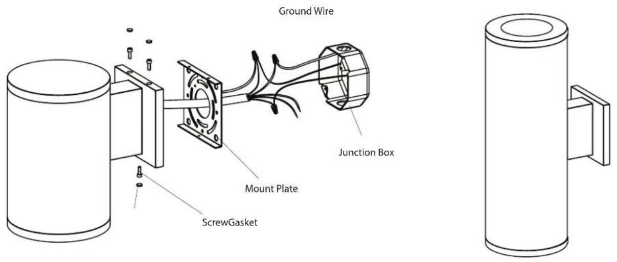
text_image
Ground Wire Junction Box Mount Plate ScrewGasketREFLECTOR REPLACEMENT
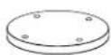
- Remove panel assembly by loosening the fixture screw and gasket, remove three chips to change reflector. (FIG.3)
- Replace your beam angle reflector on panel and fix the clips. (FIG.4)
FIG.3
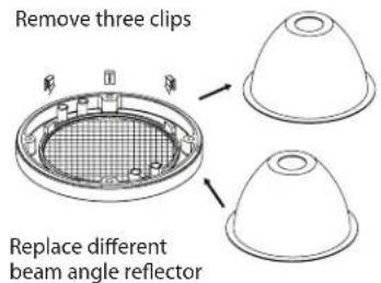
text_image
Remove three clips Replace different beam angle reflectorFIG.4
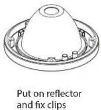
text_image
Put on reflector and fix clipsLED REPLACEMENT
- Loosen the screw and gasket (See FIG.5), remove the panel assembly (See FIG.6).
- Loosen the LED holder and LED screws, carefully disconnect LED connector from driver connector and replace LED by removing LED mounting screws. (See FIG.7).
FIG.5

natural_image
Technical line drawing of a cylindrical mechanical component with mounting flanges and a side bracket (no text or symbols)Loosen the fixture screws and gaskets
FIG.6
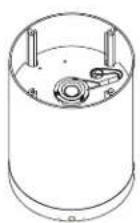
Remove panel assembly
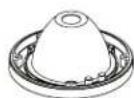
FIG.7
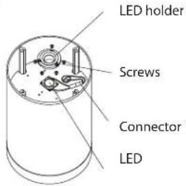
text_image
LED holder Screws Connector LEDDRIVER REPLACEMENT
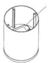
- Loosen the screw and gasket (See FIG.8), remove the cover assembly (See FIG.9).
- Loosen the LED driver screws, carefully disconnect LED driver connector from LED connector and replace driver by removing driver mounting screws. (See FIG.10).
FIG.8
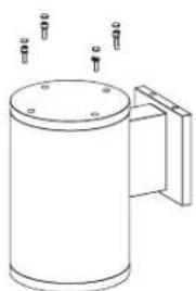
natural_image
Line drawing of a cylindrical mechanical component with mounting holes and a handle (no text or symbols)Loosen the fixture screws and gaskets
FIG.9
Remove panel assembly
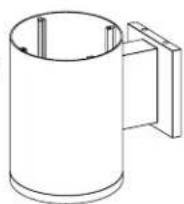
FIG.10
LED holder
COMPLETING THE INSTALLATION
To prevent moisture from entering the outlet box and causing a short, use clear caulking (i.e. indoor/outdoor silicone sealant) to outline the outside of fixture plate where it meets the wall leaving a space at bottom to allow moisture a means to escape.
waclighting.com
Phone (800) 526.2588
Fax (800) 526.2585
Headquarters/Eastern Distribution Center
44 Harbor Park Drive
Port Washington, NY 11050
Central Distribution Center
1600 Distribution Ct
Lithia Springs, GA 30122
Western Distribution Center
1750 Archibald Avenue
Ontario, CA 91760