
SMK V SB 33 Plus - Speaker Stand Extron - Free user manual and instructions
Find the device manual for free SMK V SB 33 Plus Extron in PDF.


| Product Type | Speaker Stand |
| Brand | Extron |
| Model | SMK V SB 33 Plus |
| Compatible Speaker Size | Bookshelf speakers up to 33 cm width |
| Material | Heavy-duty steel with black powder coating |
| Height Adjustment Range | 60 cm to 100 cm (continuously adjustable) |
| Maximum Load Capacity | 15 kg per stand |
| Base Dimensions | 300 mm x 300 mm |
| Top Plate Dimensions | 150 mm x 200 mm |
| Weight of Stand | 3.5 kg (each) |
| Color | Black |
| Mounting Options | Floor spikes or rubber feet included |
| Warranty | 2 years |
| Accessories Included | Mounting hardware, cable management clips, user manual |
| Safety Features | Anti-slip pads on top plate; wide base for stability |
| Maintenance | Wipe with a damp cloth; do not use harsh chemicals |
| Assembly Required | Yes, simple assembly with included tools |
| Suitable For | Indoor use only |
| Country of Origin | China |
| Package Dimensions | 80 cm x 35 cm x 15 cm |
Frequently Asked Questions - SMK V SB 33 Plus Extron
User questions about SMK V SB 33 Plus Extron
0 question about this device. Answer the ones you know or ask your own.
Ask a new question about this device
Download the instructions for your Speaker Stand in PDF format for free! Find your manual SMK V SB 33 Plus - Extron and take your electronic device back in hand. On this page are published all the documents necessary for the use of your device. SMK V SB 33 Plus by Extron.
USER MANUAL SMK V SB 33 Plus Extron
SMK V SB 33 Plus VESA Mounting Kit • Installation Guide
The SMK V SB 33 Plus VESA Mounting Kit allows the SB 33 Series of soundbar speakers to be attached to the same VESA mount supporting the display device. The SB 33 speaker front surface can be adjusted flush with the front of the display. It can be adjusted forward, backward, up, down, and side-to-side.
Installation
VESA display mounts come in a variety of different styles, so installation may vary. Please consult the installation guides for your specific VESA display mount and your display device before installing the SMK V SB 33 Plus VESA mounting kit. Follow the steps below to install the kit.
NOTE: Observe all applicable building codes and local ordinances when installing a soundbar speaker.
The SMK V SB 33 Plus VESA mounting kit is composed of 2 long L-brackets, 2 short L-brackets, 4 metal washers/spacers, 4 plastic spacers, 6 bolts, 6 lock washers, and 6 wingnuts.
-
Install the wall mount portion of the VESA display mount onto the desired wall location.
-
Position one long L-bracket of the SMK V SB 33 Plus kit on the back of the display, while aligning the bottom bolt hole on the display with a round hole on the L-bracket and the top bolt hole with one of the slotted holes.
NOTE: The L-bend of the long bracket should align with the bottom of the display device.
Repeat this procedure for the other long L-bracket on the other side of the display. Use the included plastic spacers if any portion of the display back panel protrudes further than the VESA mounting points and prevents the brackets from being seated properly.
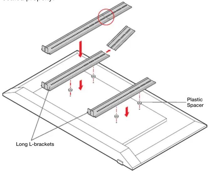
Figure 1. Installing Long L-Brackets
NOTE: The long L-brackets are designed to accommodate a variety of display heights. If the bracket is exposed over the top of the display, the top 8" (203 mm) of the SMK V SB 33 Plus long L-bracket can be broken off. To do this, simply bend the top breakaway portion back at the seam until it breaks off. (see figures 1 and 2 for details).
- Place the VESA display mount on top of the L-bracket, while aligning the bolt holes of the display mount with the bottom round hole and top slot hole of the L-bracket and the bolt hole of the display. Repeat this procedure for the other long L-bracket on the other side of the display.
NOTE: If the VESA display mount uses horizontal mounting brackets or a X-braced bracket, then insert the included four metal washer/spacers between the long L-bracket and VESA display mount.
- Insert bolts through the VESA display mounts, the long L-brackets, and the display. Be sure to align the bolt holes of the VESA display mounts with the display mounting holes and insert the bolts. Hand tighten all 4 bolts. Spacers are provided if needed (see figure 1 on the previous page).
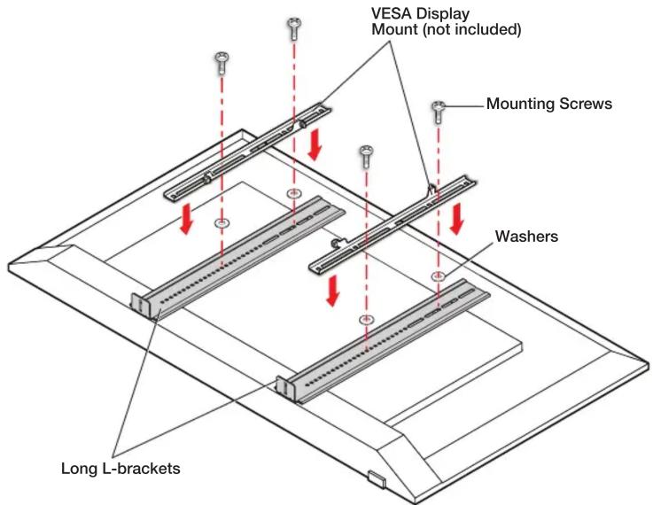
Figure 2. Installing VESA display mount
- Position the short L-bracket under the long L-bracket so that the L-bends of each bracket are paired together (see figure 3). Afterwards, install one bolt with a wingnut and lock-washer so that the long and short L-brackets are held together. Tighten the wingnut.
Repeat this procedure for the other long L-bracket on the other side of the display.
NOTE: The short L-bracket may be reversed if the soundbar needs to be positioned further forward relative to the display (see figure 3).
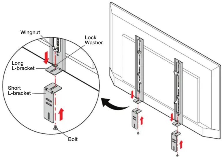

Figure 3. Installing short L-brackets on the long L-brackets
- Install the SB 33 speaker wall plate to the short L-bracket using two bolts, two lock washers, and two wingnuts as shown in figure 4.
Repeat this procedure for the other short L-bracket on the other side.

Figure 4. Installing the SB 33 speaker wall plate
- Tighten the bolts and permanently fasten the display onto the VESA wall mount previously attached in figure 2.
- To adjust the SB 33 speaker vertically:
a. Loosen, but do not remove, the bolts that attach the long L-brackets to the display.
b. Adjust the SB 33 to the desired distance from the display and then tighten the bolts.

Figure 5. Adjusting the SB 33 speaker wall plate
NOTE: Assuming the display screen is level, allow for some space between the bottom of the display screen and the top of the speaker because the speaker assemblies and the center bracket attach to the wallplate by hooking the top mounting clasps of the speaker assemblies and center bracket over the top mounting rail of the wall plate.
To allow sufficient clearance between the top of the SB 33 speaker and the display screen above it, allow for at least a minimum clearance of 11/16 inches (17.5 mm) between the highest part of the top rail of the wallplate and the top of the speaker, as shown to the right. The display screen should not encroach into this area above the top rail.
The long L-brackets for the SMK V SB 33 Plus have holes for the lower VESA holes. As a result, it may be necessary to remove the lower bolts in order to adjust the vertical height. Depending on the short L-bracket orientation and depth adjustment, it is also possible to adjust the SB 33 speaker height by adjusting the wall bracket position on the short L-bracket.

- Install the SB 33 speaker to the wall plate as shown in figure 6.
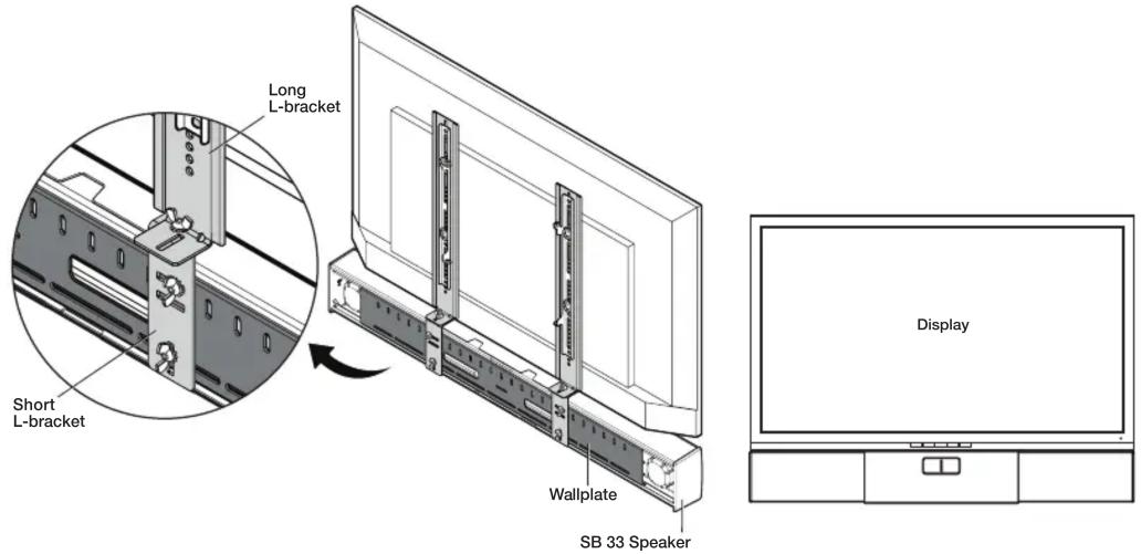
Figure 6. Installing the SB 33 speaker wall plate
- If the alignment between the display and the SB 33 speaker needs to be adjusted in order to align the front of the speaker assembly relative to front of the display, do the following:
a. Loosen, but do not remove, the two wingnuts attaching the long L-brackets to the short L-brackets.
b. Adjust the soundbar speaker to either the front or the rear of the display and then tighten the wingnuts.
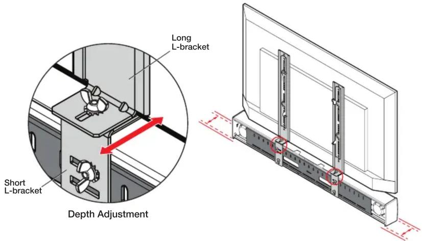
Figure 7. Adjusting Depth
For information on safety guidelines, regulatory compliances, EMI/EMF compatibility, accessibility, and related topics, see the Extron Safety and Regulatory Compliance Guide on the Extron website.


Brand : Extron
Model : SMK V SB 33 Plus
Category : Speaker Stand