
V-Lock - Speaker Stand Extron - Free user manual and instructions
Find the device manual for free V-Lock Extron in PDF.


| Product Type | Speaker Stand |
| Brand | Extron |
| Model | V-Lock |
| Height Range | 1.2 m to 1.8 m (adjustable) |
| Base Diameter | 80 cm (32 inches) |
| Weight Capacity | Up to 30 kg (66 lbs) |
| Net Weight | 5.2 kg (11.5 lbs) |
| Material | Steel with powder-coated finish |
| Locking Mechanism | V-Lock secure locking system |
| Height Adjustment | Clamp-style with locking pin |
| Speaker Mount | Top plate with M8 thread insert |
| Power Source | None (passive stand) |
| Maintenance | Wipe clean with damp cloth; check fasteners regularly |
| Safety Features | Non-slip feet, safety pin, anti-tip base |
| Warranty | Limited lifetime warranty |
| Spare Parts Availability | Contact Extron support or authorized dealers |
Frequently Asked Questions - V-Lock Extron
User questions about V-Lock Extron
0 question about this device. Answer the ones you know or ask your own.
Ask a new question about this device
Download the instructions for your Speaker Stand in PDF format for free! Find your manual V-Lock - Extron and take your electronic device back in hand. On this page are published all the documents necessary for the use of your device. V-Lock by Extron.
USER MANUAL V-Lock Extron
natural_image
Close-up of a black wall-mounted device with circular components and a spherical lens, no visible text or symbols.V-Lock™ Wall Mount Assembly Kit
Replacement accessory for Extron System INTEGRATOR®
SI 3 Surface Mount Speakers
68-1490-01
Rev. A
03 08
Packaging Information
The V-Lock ^™ Assembly Kit contains two individually packed wall mount assemblies (one for each speaker) and an Allen hex tool.
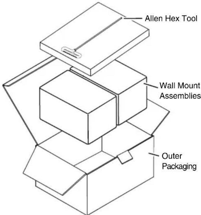
Figure 1 — V-Lock Assembly packaging details
About the V-Lock Assembly Kit
The V-Lock Wall Mount Assembly Kit is a pair of replacement wall mount assemblies (wall plate and V-lock groove only) for the Extron System INTEGRATOR® SI 3 surface mount speakers.

Figure 2 — Main parts of the V-Lock Assembly Kit
Installing the V-Lock™ Assembly Kit
If your speakers are not already installed, follow the instructions outlined in the SI 3 User's Guide supplied with the speakers (or online at www.extron.com).
If your speakers are already installed, replace the V-Lock assembly by following the instructions, below.
NOTE Referring to packaging information for location, carefully remove and check contents before installation.
NOTE Extron recommends that the wiring installation is performed by a professional audio equipment installer.
NOTE For speaker details, specifications, troubleshooting tips, and service access information, refer to the SI 3 User's Guide supplied with the speakers, or online at www.extron.com.
Existing wall mounting application
To replace a damaged V-Lock assembly that is already installed, do the following:
- Remove the Extron logo from the front of the speaker to access the hex cap screw. Retain the logo.
- Insert the hex tool and unlock the speaker.
- Carefully lift the speakers away from the bracket, then disconnect the seismic cable and audio wires from the rear of the speakers.
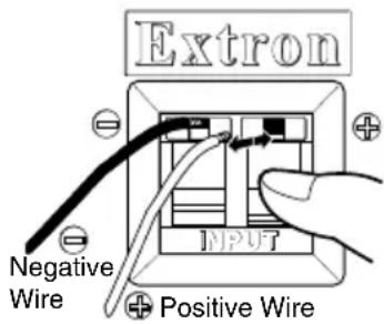
To remove (or insert) the wires, push down on the spring terminals at the back of the speaker. Release the springs to secure.
Figure 3 — Remove audio wires from the terminals
NOTE If the ends of the wires are damaged and need to be re-stripped, follow the instructions in the SI 3 User's Guide.
- Rotate the stage (V-lock groove) 90 degrees to the wall plate (see figure 4), to access the screws in the wall plate.

Figure 4 — Remove the old V-Lock Assembly
-
Carefully remove and retain the mounting screws, taking care not to damage the mounting holes in the wall. Remove the mount from the wall.
-
Remove a new V-Lock assembly from its box, loosen the hex cap screw and rotate the front section approximately 90 degrees to the mounting plate (see figure 4). Lightly tighten the hex cap screw to temporarily lock it in position, allowing access to the mounting holes in the wall plate.
-
Pass the wire through the access hole in the wall plate and using the existing mounting holes and screws, securely mount the new assembly wall plate to the wall.
NOTE If the mounting holes in the wall are damaged and unusable, or a new location is desired, create new mounting holes, following the instructions in the SI 3 User's Manual.
-
Loosen the hex cap screw and turn the stage back to its upright position. Retighten the hex cap screw to lock it in place.
-
Reattach the seismic cable to the speaker (see figure 5). Insert the speaker wires (see figure 3).
Anchor this end to a suitable secure point.

Figure 5 — Re-attach the seismic safety cable
Mounting the speakers
- Carefully lift the speaker above the wall mount assembly and gently slide the speaker box bracket down into the V-lock groove (see figure 6) until it locks into place.
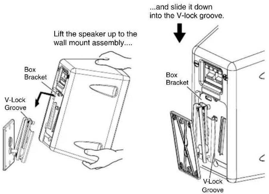
Figure 6 — Slide the speaker down onto the wall mount assembly
- If re-installing two speakers, repeat all the installation and speaker mounting steps for the second speaker.
Final adjustments
-
Turn on the audio source and any associated devices. Adjust the source and device settings as desired to get the optimum audio output for your speaker application.
-
To adjust the speaker angle insert the allen hex tool into the locking access, loosen the hex cap screw, and adjust to the desired angle (see figure 7). Tighten the hex cap screw down about 6 to 8 turns clockwise, until snug, for the speaker to sit securely in the desired position.
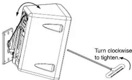
Figure 7 — Adjust speaker and lock in place
NOTE After locking it into place, check that the speaker is secure and cannot be lifted from the wall mount assembly. If it does lift out, continue tightening the hex cap screw until it is no longer possible to lift the speaker from the assembly.
- Replace the Extron logo, pressing it firmly into place.
NOTE For speaker details, specifications, troubleshooting tips, and service access information refer to the SI 3 User's Guide supplied with the speakers, or online at www.extron.com
Extron's Warranty
Extron Electronics warrants this product against defects in materials and workmanship for a period of five years from the date of purchase. In the event of malfunction during the warranty period attributable directly to faulty workmanship and/or materials, Extron Electronics will, at its option, repair or replace said products or components, to whatever extent it shall deem necessary to restore said product to proper operating condition, provided that it is returned within the warranty period, with proof of purchase and description of malfunction to:
USA, Canada, South America, Europe, Africa, and the Middle East:
and Central America: Extron Electronics, Europe
Extron Electronics Beeldschermweg 6C
1001 East Ball Road 3821 AH Amersfoort
Anaheim, CA 92805, USA The Netherlands
Asia: Japan:
Extron Electronics, Asia Extron Electronics, Japan
135 Joo Seng Road, #04-01 Kyodo Building
PM Industrial Bldg. 16 Ichibancho
Singapore 368363 Chiyoda-ku, Tokyo 102-0082
Japan
This Limited Warranty does not apply if the fault has been caused by misuse, improper handling care, electrical or mechanical abuse, abnormal operating conditions or non-Extron authorized modification to the product.
If it has been determined that the product is defective, please call Extron and ask for an Applications Engineer at (714) 491-1500 (USA), 31.33.453.4040 (Europe), 65.6383.4400 (Asia), or 81.3.3511.7655 (Japan) to receive an RA# (Return Authorization number). This will begin the repair process as quickly as possible.
Units must be returned insured, with shipping charges prepaid. If not insured, you assume the risk of loss or damage during shipment. Returned units must include the serial number and a description of the problem, as well as the name of the person to contact in case there are any questions.
Extron Electronics makes no further warranties either expressed or implied with respect to the product and its quality, performance, merchantability, or fitness for any particular use. In no event will Extron Electronics be liable for direct, indirect, or consequential damages resulting from any defect in this product even if Extron Electronics has been advised of such damage.


Brand : Extron
Model : V-Lock
Category : Speaker Stand