Vunit 3000 - Processor NovaStar - Free user manual and instructions
Find the device manual for free Vunit 3000 NovaStar in PDF.

| Product Type | Processor |
| Brand | NovaStar |
| Model | Vunit 3000 |
| Weight | Approx. 5 kg |
| Dimensions (W x H x D) | 482.6 x 44 x 300 mm (1U rack mount) |
| Power Supply | AC 100-240V, 50/60Hz, 150W max |
| Input Ports | 1x HDMI, 1x DVI, 1x 3G-SDI, 1x VGA |
| Output Ports | 4x Ethernet (for LED sending cards) |
| Max Input Resolution | 1920x1200@60Hz |
| Max Output Load | Up to 2.6 million pixels per Ethernet port |
| Color Depth | 10-bit per color (30-bit total) |
| Processing Features | Image scaling, color calibration, gamma correction, test pattern generation |
| Cooling | Built-in fan, intelligent speed control |
| Operating Temperature | 0°C to 40°C |
| Storage Temperature | -20°C to 60°C |
| Humidity | 10% to 90% (non-condensing) |
| Control Software | NovaStar NovaLCT (Windows) |
| Firmware Update | Via USB or Ethernet using NovaStar tools |
| Mounting | 19-inch rack mountable (1U) |
| Accessories Included | Power cord, user manual, rack ears, screws |
Frequently Asked Questions - Vunit 3000 NovaStar
User questions about Vunit 3000 NovaStar
0 question about this device. Answer the ones you know or ask your own.
Ask a new question about this device
Download the instructions for your Processor in PDF format for free! Find your manual Vunit 3000 - NovaStar and take your electronic device back in hand. On this page are published all the documents necessary for the use of your device. Vunit 3000 by NovaStar.
USER MANUAL Vunit 3000 NovaStar
Professional Control Processor

natural_image
Abstract geometric composition of colorful 3D shapes (no text or symbols)User Manual
Change History
| Document Version | Release Date | Description |
| V1.0.0 | 2024-03-20 | First release |
Contents
Change History......i
1 Control Connections....1
1.1 Control Connections....1
1.2 Software Installation .... 1
1.2.1 Obtaining 1
1.2.2 Installation....2
2 Menu Operations .... 3
2.1 Switch Screen....3
2.2 Menu Functions....4
2.2.1 Return to Home Screen....4
2.2.2 Network Settings....5
2.2.3 Firmware Version....5
2.2.4 Advanced Settings 6
2.2.4.1 Serial Port Settings....6
2.2.4.2 I/O Settings....7
2.2.4.3 IR Settings....8
2.2.4.4 USB Impot/Export 8
2.2.4.5 Firmware Update 9
2.2.4.6 Factory Reset....10
2.2.5 Language....10
2.2.6 About Us....11
3 Device Connections....12
3.1 Connect Devices ....12
3.2 Change IP Information....13
3.3 Batch Change IP Information ....14
4 Configure Devices....16
4.1 Change Device Names....16
4.2 Update Firmware....17
4.2.1 Update Single Device....17
4.2.2 Batch Update....18
4.3 Synchronize Device Clocks....19
4.4 Run Diagnostics ....20
4.5 Factory Reset 21
5 Configure Central Control Devices....22
5.1 Read Back Device Information ....22
5.2 Configure Connector Parameters....22
5.2.1 Configure Serial Port Parameters....23
5.2.2 Configure I/O Modes....24
5.2.3 Configure CAN Modes 24
5.3 Configure Matrices....25
5.3.1 Set Input and Output Relationships ....25
5.3.2 Configure EDID....27
5.3.3 Save Presets ....28
5.4 Configure Events 29
5.4.1 Configure Serial Port Events 30
5.4.2 Configure I/O Events....33
5.4.3 Configure IR Events 34
5.4.4 Configure Relay Events 35
5.4.5 Configure Delay Events....36
5.4.6 Configure Ethernet Port Events....37
5.4.7 Configure CAN Events 39
5.4.8 Other Operations....40
5.5 Configure Timeline....40
5.6 Configure Triggers 43
5.6.1 Configure Conditional Triggers 44
5.6.2 Configure Scheduled Triggers 46
5.6.3 Other Operations....47
5.7 Configure IR Command Library....48
5.7.1 Configure IR Device Levels 48
5.7.2 Configure IR Learning....49
5.7.3 Other Operations....50
5.8 Project Files....51
5.8.1 Import Project Files....51
5.8.2 Export Project Files....51
5.8.3 Send to Device....52
5.9 Manage Logs....53
6 Language....54
1 Control Connections
1.1 Control Connections
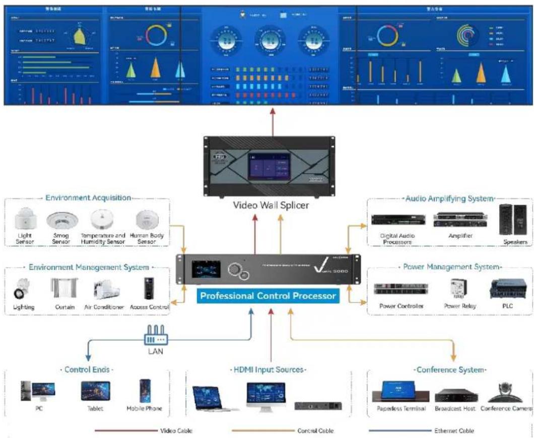
Figure 1-1 Device control connections
flowchart
graph TD
    A["Professional Control Processor"] --> B["Video Wall Splicer"]
    A --> C["Environment Acquisition"]
    A --> D["Audio Amplifying System"]
    A --> E["Environment Management System"]
    A --> F["Power Management System"]
    A --> G["Control Ends"]
    A --> H["HDMI Input Sources"]
    A --> I["Conference System"]

    B --> J["Light Sensor"]
    B --> K["Smog Sensor"]
    B --> L["Temperature and Humidity Sensor"]
    B --> M["Human Body Sensor"]

    C --> N["Digital Audio Processors"]
    C --> O["Amplifier"]
    C --> P["Speakers"]

    D --> Q["Lighting"]
    D --> R["Curtain"]
    D --> S["Air Conditioner"]
    D --> T["Access Control"]

    E --> U["Power Controller"]
    E --> V["Power Relay"]
    E --> W["PLC"]

    G --> X["PC"]
    G --> Y["Tablet"]
    G --> Z["Mobile Phone"]

    H --> AA["Paperless Terminal"]
    H --> AB["Broadcast Host"]
    H --> AC["Conference Camera"]

    I --> AD["Paperless Terminal"]
    I --> AE["Broadcast Host"]
    I --> AF["Conference Camera"]

    style A fill:#f9f,stroke:#333
    style B fill:#ccf,stroke:#333
    style C fill:#cfc,stroke:#333
    style D fill:#fcc,stroke:#333
    style E fill:#cff,stroke:#333
    style F fill:#ffc,stroke:#333
    style G fill:#cfc,stroke:#333
    style H fill:#cfc,stroke:#333
    style I fill:#cfc,stroke:#333
    style J fill:#fff,stroke:#333
    style K fill:#fff,stroke:#333
    style L fill:#fff,stroke:#333
    style M fill:#fff,stroke:#333
    style N fill:#fff,stroke:#333
    style O fill:#fff,stroke:#333
    style P fill:#fff,stroke:#333
    style Q fill:#fff,stroke:#333
    style R fill:#fff,stroke:#333
    style S fill:#fff,stroke:#333
    style T fill:#fff,stroke:#333
    style U fill:#fff,stroke:#333
    style V fill:#fff,stroke:#333
    style W fill:#fff,stroke:#333
1.2 Software Installation
1.2.1 Obtaining
You can obtain the installation package of BCTools via the following two ways.
- Obtain the installation package from the device provider and copy it to your computer.
- Contact your sales engineer or our technical support engineer to obtain the installation package and copy it to your computer.
1.2.2 Installation
Uncompress the software package to your computer, and then double click the installation package named BCTools.exe. Follow the instructions to complete the installation.
You can install BCTools on Windows 7 or later only.
2 Menu Operations
Operating Instructions:
- Knob:
- On the home screen, press the knob to enter the operation menu screen.
- On the home screen, rotate the knob to view the device overall status and backplane connector status.
- On the operation menu screen, rotate the knob to select a menu item and press the knob to confirm the selection or enter the submenu.
- When a menu item with parameters is selected, you can rotate the knob to adjust the parameters. Please note that after the adjustment, you need to press the knob again to confirm the adjustment.
- ESC: Exit the current menu or cancel an operation.
- Hold down the knob and ESC button simultaneously for 3s or longer to lock or unlock the front panel buttons.
2.1 Switch Screen
After the device is successfully powered on, the device status is displayed by default as shown in Figure 2-1. Rotate the knob to view backplane connector status as shown in Figure 2-2.
Figure 2-1 Device status
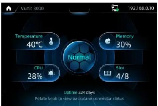
The device IP address is displayed at the top right of the screen. The default IP address is 192.168.0.10.
Figure 2-2 Backplane connector status
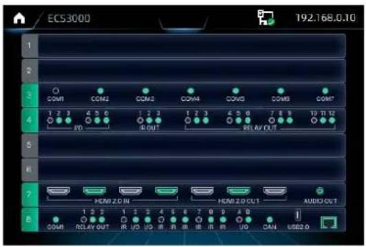
Descriptions for the connector status:
- Green: The connector is connected normally.
- White: The connector is not connected.
The empty card slot indicates that no card is installed.
2.2 Menu Functions
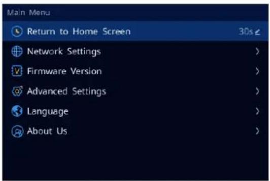
Press the knob to enter the main menu screen.
Figure 2-3 Main menu
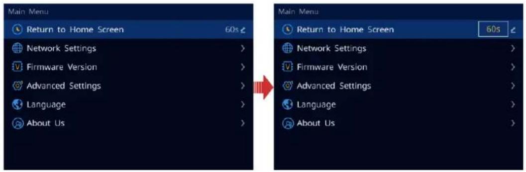
2.2.1 Return to Home Screen
You can set the period when the system stays at the current screen before returning to the homepage automatically when no operation is performed.
On the main menu screen, select Return to Home Screen and press the knob to confirm. Rotate the knob to select the desired duration and press the knob to confirm. The value ranges from 60s to 3600s.
Figure 2-4 Return to home screen
2.2.2 Network Settings
When a control PC is used for device control, ensure that the device and the control PC are on the same network segment and the device IP address must not conflict with the IP address of the control PC.
Step 1 On the main menu screen, rotate the knob to select Network Settings and press the knob to enter the corresponding screen.
Step 2 Rotate the knob to select IP Address and press the knob to enable IP address settings.
Step 3 Rotate the knob to set the fourth section of the device IP address and press the knob to confirm.
Step 4 Set other sections of the IP address.
Figure 2-5 Network settings
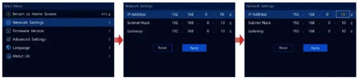
Step 5 Set the subnet mask and gateway respectively.
Step 6 Rotate the knob to select Apply to make the settings take effect.
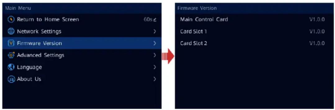
2.2.3 Firmware Version
Under this menu item, you can view the firmware versions of the main control card and other cards.
On the main menu screen, rotate the knob to select Firmware Version and press the knob to show the relevant information.
Figure 2-6 Firmware version
2.2.4 Advanced Settings
The advanced settings allow you to set the serial port, I/O port, IR, device update, factory reset and USB import/export.
2.2.4.1 Serial Port Settings
Step 1 On the main menu screen, rotate the knob to select Advanced Settings and press the knob to enter the advanced settings screen.
Step 2 On the advanced settings screen, rotate the knob to select Serial Port and press the knob to enter the serial port settings screen.
Figure 2-7 Serial port settings
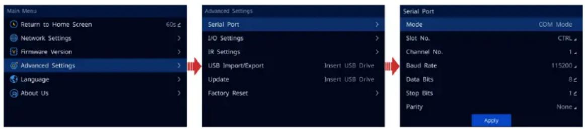
- Mode: View the work mode of the serial port. The supported options include COM Mode and Modbus-ASCII Mode. The mode can be only read from the device and cannot be set on the screen.
- Slot No.: Select the slot number of the corresponding card where the COM port is located.
CTRL: Main control card
- Channel No.: Select the channel number of the corresponding card where the COM port is located.
- Baud Rate, Data Bits, Stop Bits and Parity: Set the communication parameters between the COM port and the controlled device. Please refer to the relevant parameters of the controlled device for configuration.
Step 3 Rotate the knob to select Apply and press the knob to confirm.
2.2.4.2 I/O Settings
Step 1 On the main menu screen, rotate the knob to select Advanced Settings and press the knob to enter the advanced settings screen.
Step 2 On the advanced settings screen, rotate the knob to select I/O Settings and press the knob to enter the I/O settings screen.
Figure 2-8 I/O settings
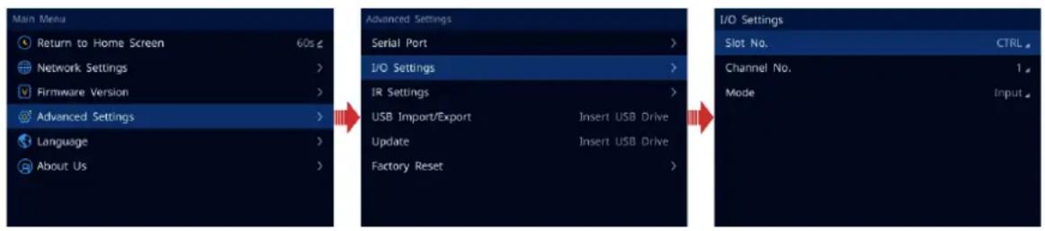
- Slot No.: Select the slot number of the corresponding card where the I/O port is located.
CTRL: Main control card
- Channel No.: Select the channel number of the corresponding card where the I/O port is located.
- Mode: The supported modes include Input, Output-High, Output-Low. Select one of the modes according to the connected device.
- When the I/O connector is connected to the device for signal input, such as smoke sensors, and temperature and humidity sensors, you need to set the I/O mode to Input.
- When the controlled device is connected and the I/O connector is used for control, you need to set the mode to Output-High or Output-Low according to the signal received by the controlled device.
Step 3 Press the ESC to exit the current menu and apply the configuration.
2.2.4.3 IR Settings
Step 1 On the main menu screen, rotate the knob to select Advanced Settings and press the knob to enter the advanced settings screen.
Step 2 On the advanced settings screen, rotate the knob to select IR Settings and press the knob to enter the IR settings screen.
Figure 2-9 IR settings
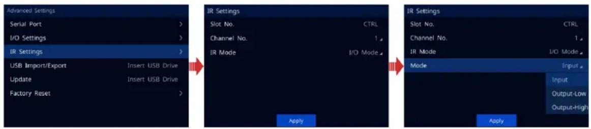
- Slot No. Select the slot number of the corresponding card where the IR port is located.
CTRL: Main control card - Channel No.: Select the channel number of the corresponding card where the IR port is located.
- IR Mode: If the selected IR port is located on the main control card, you can set the IR mode to IR Mode or I/O Mode. If the selected IR port is not located on the main control card, only IR Mode is supported.
- IR Mode: The current connector is used for the IR port only.
- I/O Mode: Set the current connector as the I/O port.
- Mode: When the IR mode is set to I/O Mode, you need to select the connector mode for each connected device.
2.2.4.4 USB Impot/Export
You can export the configuration information to your local computer via a USB drive, or import the configuration file saved in the USB drive to the device for quick configuration.
On the main menu screen, go to Advanced Settings > USB Import/Export and press the knob to enter the corresponding screen.
Figure 2-10 USB import/export
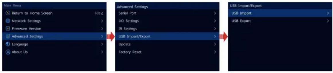
- Import: Import the configuration file saved in the USB drive to the Vunit 3000.
- Export: Export the configuration information to the USB drive.
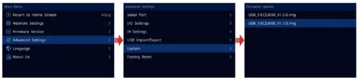
2.2.4.5 Firmware Update
The Vunit 3000 allows you to update the device via a USB drive. Before updating, you need to save the update program to the root directory of the USB drive.
Step 1 Insert a USB drive into the USB port on the device front panel or the USB port on the main control card.
Step 2 Press the knob to enter the main menu screen.
Step 3 Go to Advanced Settings > Update and press the knob to enter the firmware update screen.
Step 4 Rotate the knob to select the desired update program saved in the USB drive.
Figure 2-11 Firmware update
Step 5 Press the knob to enable the firmware update function.
Step 6 Carefully view the prompt message, rotate the knob to select OK and press the knob to confirm. The firmware will be updated automatically.
Figure 2-12 Updating firmware
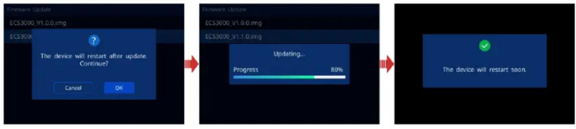
After the firmware is updated successfully, the device will restart automatically. After the restarting is complete, rotate the knob to select Firmware Version and press the knob to enter the corresponding screen where you can view the device and card versions.
2.2.4.6 Factory Reset
Factory reset function allows you to reset all the parameter settings of the device to factory defaults after the device update or when you think the parameters are improperly set.
On the main menu screen, go to Advanced Settings > Factory Reset and press the knob to enter the factory reset screen.
Figure 2-13 Factory reset
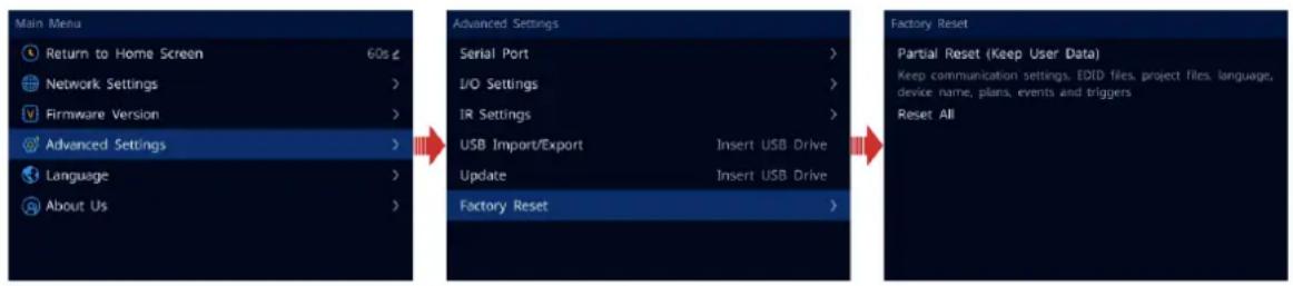
- Partial Reset (Keep User Data): Reset the parameter settings to factory defaults, except for the communication settings, EDID files, project files, language, device name, plans, events and triggers.
- Reset All: Reset all the parameter settings to factory defaults.
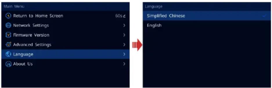
2.2.5 Language
The language options include English and Simplified Chinese. You can switch to your preferred language.
Figure 2-14 Language switching
2.2.6 About Us
Under this menu item, you can view the official website and email address. On our official website, you can check the latest device information and the updates for this device. You can also send your feedback or suggestion to us for improvements via the supplied email address.
3 Device Connections
3.1 Connect Devices
Prerequisites
The Vunit 3000 and control PC must be on the same network segment.
Operating Procedure
Step 1 Double click the BCTools shortcut icon to run the control end.
Step 2 In the popup window, select the network card that is installed on the control PC.
Figure 3-1 Select network card
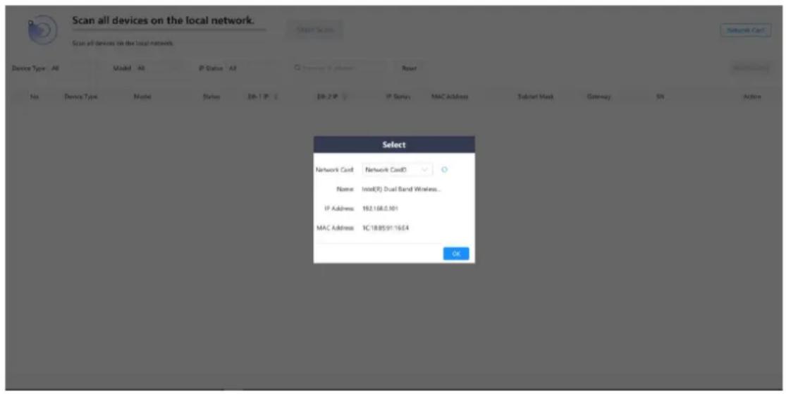
Notes:
- If only one network card can be connected to the control PC, there is no need to set the network card.
- You can also open the network card selection window by clicking Network Card at the top right corner.
Step 3 Click OK to complete the connected network card settings.
Figure 3-2 Network card set successfully
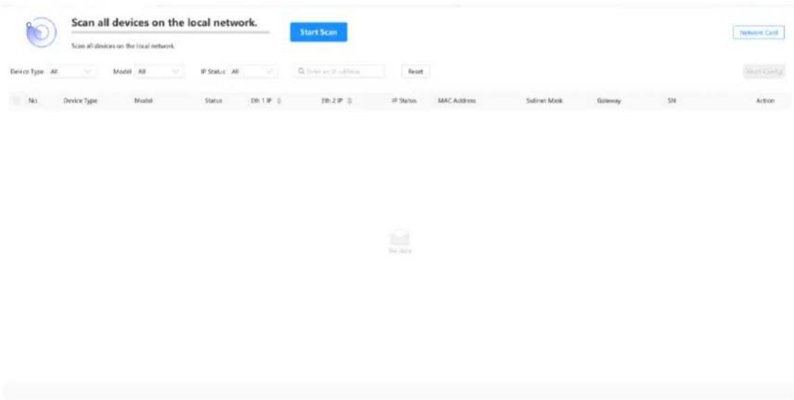
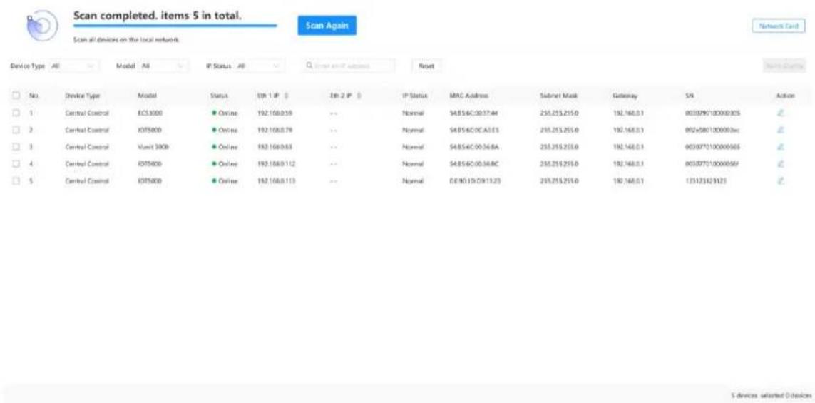
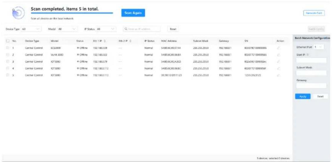
Step 4 Click Start Scan and the system will automatically scan the MAC addresses of all the Vunit 3000 on the current network segment, and then display the scanned devices.
Figure 3-3 Scan devices
3.2 Change IP Information
Prerequisites
The device is connected in BCTools.
Operating Procedure
Step 1 In the device list, click 🔒 in the column of Action to expand the Network Configuration pane.
Figure 3-4 Network configuration
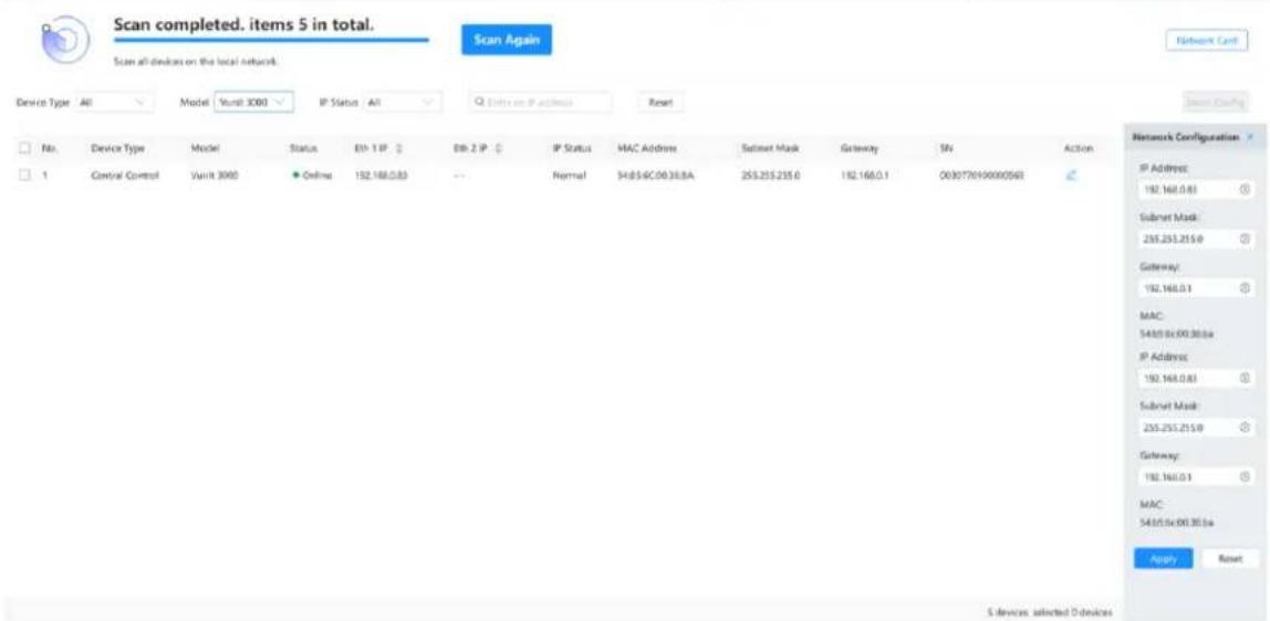
Step 2 Set the device IP address, subnet mask and gateway.
The IP address you set must not conflict with IP addresses of other devices on the current network segment.
Step 3 Click Apply to complete and apply the change.
3.3 Batch Change IP Information
You can batch change the IP information of the connected Vunit 3000 units in BCTools.
Prerequisites
The device is connected in BCTools.
Operating Procedure
Step 1 Check the boxes in front of the desired devices.
Check the box in front of No. to select all the connected devices.
Figure 3-5 Batch select devices
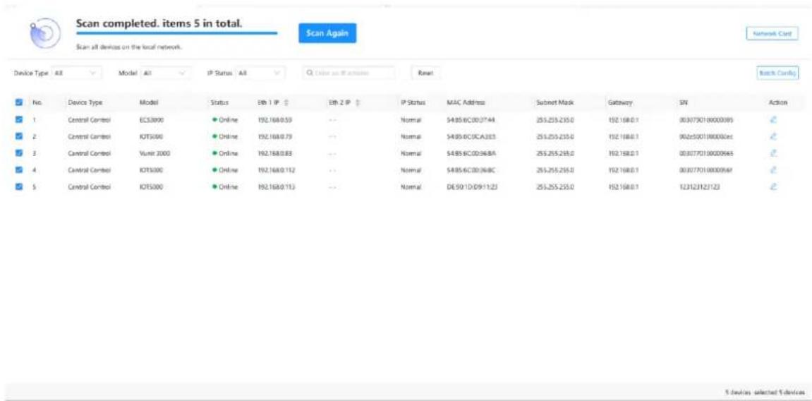
Step 2 Click Batch Config to expand the Batch Network Configuration pane.
Figure 3-6 Batch network configuration
Step 3 Enter the device start IP address in the text box below Start IP.
After the start IP address is set successfully, the IP addresses of other devices are increased sequentially by one according to the order of the device.
For example, the start IP address is 192.168.0.10, and the IP address of the second device in the device list is 192.168.0.11.
Step 4 Set the subnet mask and gateway respectively.
Step 5 Click Apply to complete and apply the configurations.
4 Configure Devices
4.1 Change Device Names
After the devices are connected successfully, their default names are the same. You can change the device name to distinguish different devices.
Change Single Device Name
Step 1 Click the Device Configuration tab to enter the device configuration page.
Step 2 Click in the column of Action to expand the Configure Properties pane where you can change the target device name.
Figure 4-1 Change device name
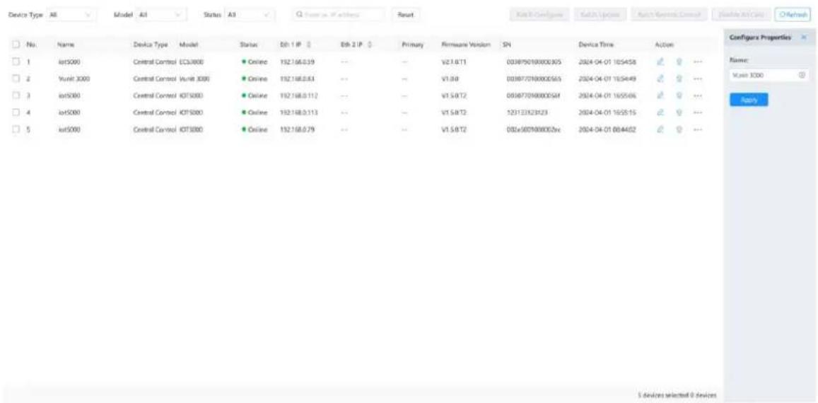
Step 3 Enter a new name in the text box.
Step 4 Click Apply to complete and apply the change.
Batch Change Device Names
Step 1 Click the Device Configuration tab to enter the device configuration page.
Step 2 Check the boxes in front of the desired devices.
Check the box in front of No. to select all the connected devices.
Step 3 Click Batch Configure to expand the Batch Configure pane where you can batch change the target device names.
Figure 4-2 Batch change device names
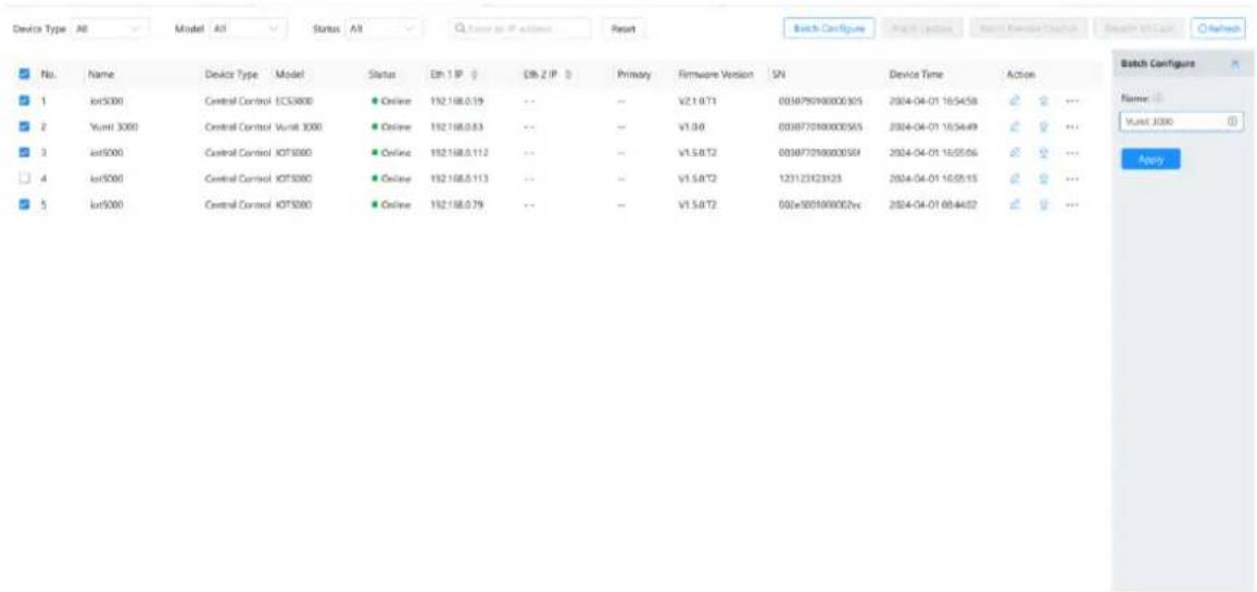
Step 4 Enter a new name in the text box.
Step 5 Click Apply to complete and apply the change.
After the device name is set successfully, other device names are followed by a serial number starting from 1.
For example, if you enter Vunit 3000 in the text box, the name of the first device in the device list is Vunit 3000-1 and the name of the second one is Vunit 3000-2.
4.2 Update Firmware
You can update the whole device or the desired card in BCTools.
After the whole device or main control card is updated, the device will restart automatically.
4.2.1 Update Single Device
Prerequisites
You have obtained the update package.
Operating Procedure
Step 1 On the Device Configuration page, select the desired device from the device list.
Step 2 Click ↑ in the column of Action to open the firmware update window.
Figure 4-3 Firmware update
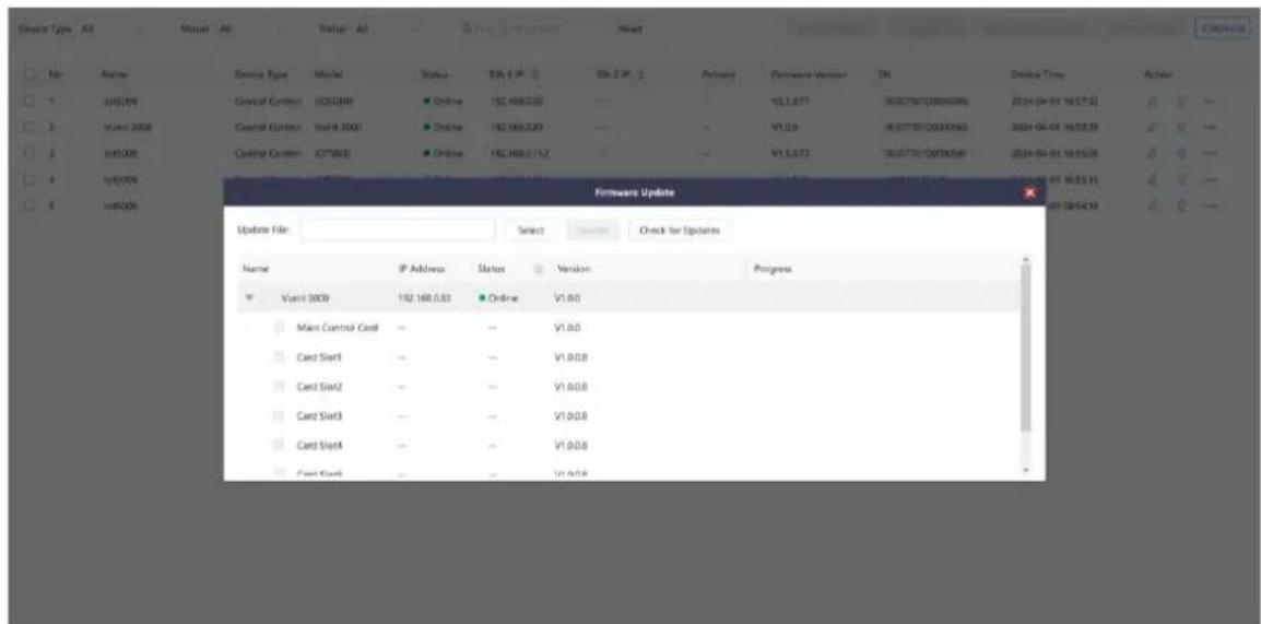
Step 3 Click Select and then select the obtained update package.
Step 4 Check the box in front of the desired card or device.
If you want to update the main control card or other corresponding cards, only check the box in front of the desired card slot number.
Step 5 Click Update and the system will automatically update the selected device or card.
4.2.2 Batch Update
Prerequisites
You have obtained the update package.
Operating Procedure
Step 1 On the Device Configuration page, check the boxes in front of the desired devices.
Step 2 Click Batch Update to open the firmware update window.
Figure 4-4 Batch update
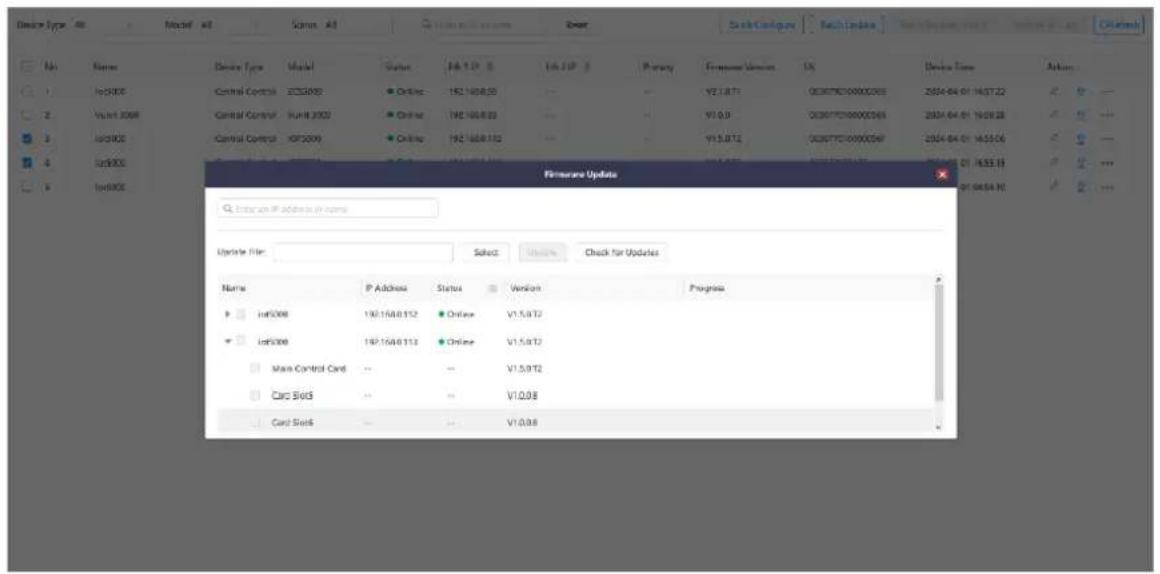
Step 3 Check the boxes in front of the desired devices or corresponding cards installed on the devices.
Step 4 Click Update and the system will automatically update the selected devices or cards.
Click Check for Updates to read back the device version information, which can be used to check the version before and after update.
4.3 Synchronize Device Clocks
When you schedule the events based on time, make sure the device reference time is accurate to guarantee precise execution of the events.
Step 1 On the Device Configuration page, select the desired device from the device list.
Step 2 Click ... in the column of Action to open the time sync window.
Figure 4-5 Time synchronization
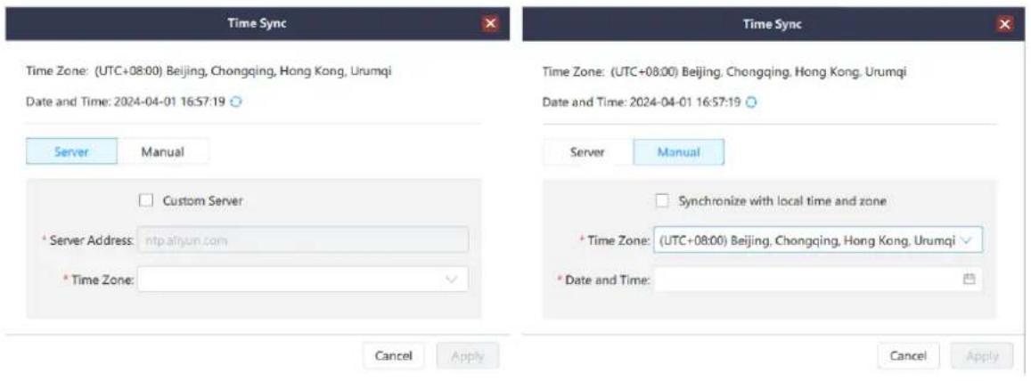
You can synchronize the device clock via two methods, including Server and Manual.
- Server: When you synchronize the device clock via a server, make sure the communication between the device and server used for time synchronization is normal.
a. Select the time zone where the device is located from the drop-down list next to Time Zone.
b. Enter the IP address of the server used for time synchronization in the text box next to Server Address.
- Manual
c. Select the time zone where the device is located from the drop-down list next to Time Zone.
d. Click the date/time picker on the right side of the text box next to Date and Time.
Step 3 Click Apply to complete and apply the configurations.
4.4 Run Diagnostics
Diagnose the device and send the test result to our technical support staff for confirming and fixing the problems as soon as possible.
Step 1 On the Device Configuration page, select the desired device from the device list.
Step 2 Click *** in the column of Action and then select Diagnose.
Step 3 Click OK in the popup window and the system will automatically run diagnostics.
Step 4 After the diagnostics is complete, the test result will be displayed.
Figure 4-6 Run diagnostics
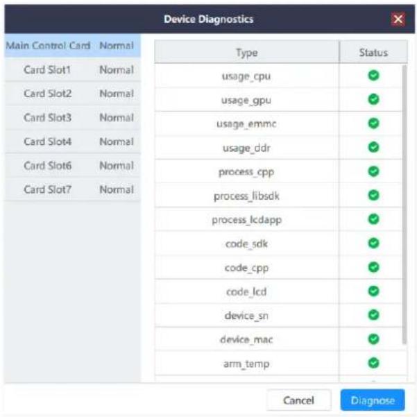
Step 5 Send the test result to our technical support staff for confirming and fixing the problems as soon as possible.
4.5 Factory Reset
When you need to reconfigure or change the control device, you can quickly clear the saved information using the factory reset function.
Step 1 On the Device Configuration page, select the desired device from the device list.
Step 2 Click ... in the column of Action and then select Reset to open the factory reset window.
Figure 4-7 Factory Reset
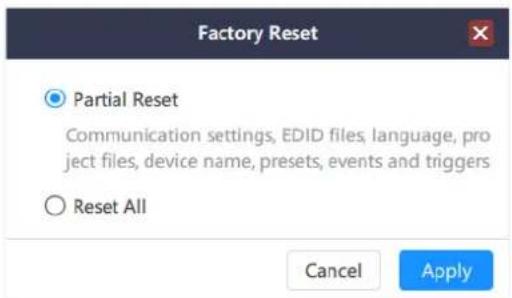
- Keep User Data: When you reset the device, the following information will still be kept in the system, including the communication settings, EDID files, project files, device name, presets, events and triggers.
- Reset All: Reset all the parameters to factory defaults.
5 Configure Central Control Devices
Click the Central Control Configuration tab to enter the corresponding page.
Figure 5-1 Central control configuration
5.1 Read Back Device Information
After the device is connected in BCTools, the device related information will be automatically read back. When multiple users are editing the device, the device information can be manually read back.
Step 1 On the Central Control Configuration page, select the desired device form the device list on the left.
Step 2 Click Read Back and the system will automatically re-read the device information and display the latest information.
5.2 Configure Connector Parameters
Step 1 Click the Central Control Configuration tab to enter the corresponding page.
The connector parameters are displayed by default.
Step 2 Select the desired device form the device list on the left.
Step 3 Click Apply to complete and apply the configurations.
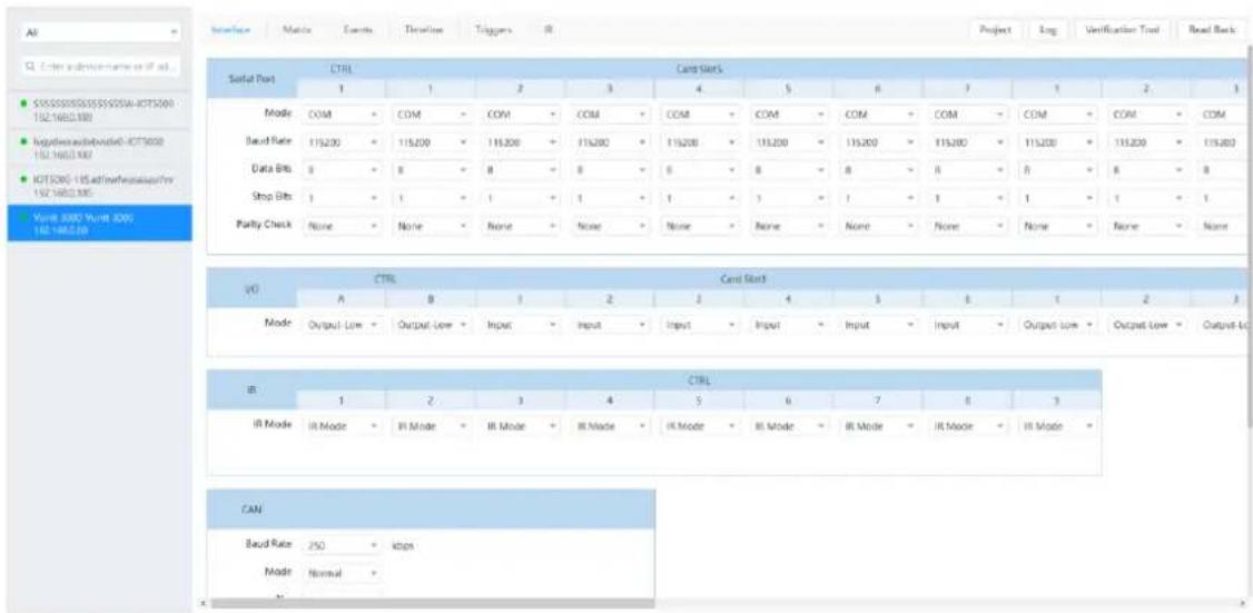
Figure 5-2 Configure connector parameters
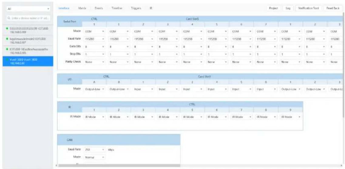
5.2.1 Configure Serial Port Parameters
When the Vunit 3000 is connect to the control device via a serial port, you need to configure the communication parameters of the serial port and control device to ensure normal communication.
The supported communication modes include COM, Modbus and DMX. Select one of the modes according to the control protocol supported by the controlled device.
Figure 5-3 Configure serial port parameters
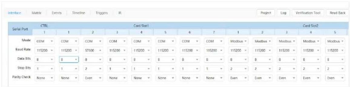
The parameters of COM and Modbus modes are the same, including the baud rate, data bits, stop bits and parity check. All the parameters need to be the same as the controlled device.
The supported options of the baud rate include 1200, 1800, 2400, 4800, 9600, 19200, 38400, 57600 and 115200 (default).
5.2.2 Configure I/O Modes
The supported I/O modes include Input, Output-High and Output-Low. Select one of the modes according to the connected device.
When the I/O connector is connected to the device for signal input, such as smoke sensors, temperature and humidity sensors, you need to set the I/O mode to Input.
When the controlled device is connected and the I/O connector is used for control, you need to set the I/O mode to Output-High or Output-Low according to the signal received by the controlled device.
Figure 5-4 I/O modes
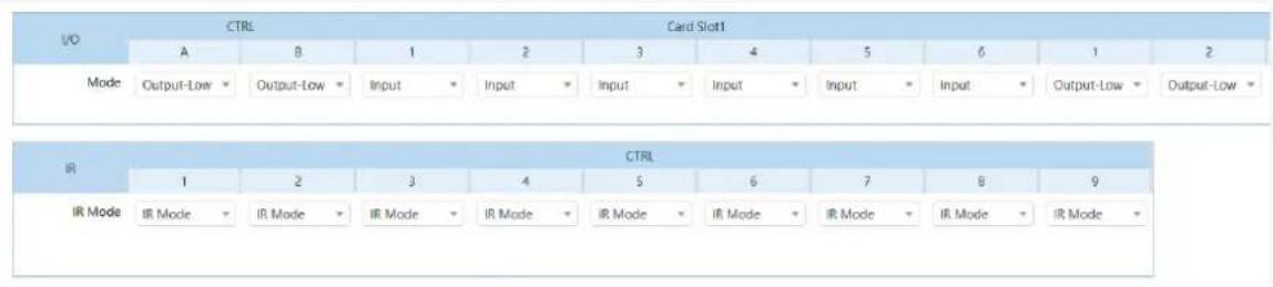
The IR connector on the main control card supports IR Mode and I/O Mode. When I/O Mode is selected, you can set the input and output mode of the I/O connector.
5.2.3 Configure CAN Modes
When the Vunit 3000 is connect to the controlled device via a CAN port, you need to configure the communication parameters of the CAN port and control device to ensure normal communication.
Figure 5-5 Configure CAN ports
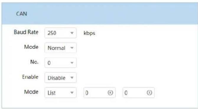
- Baud Rate: You can customize the baud rate value, which ranges from 3 to 1000 Kbps and defaults to 250. The unit is Kbps.
- Mode: The supported options include Normal (default) and Loopback.
- No.: The value is an integer from 0 (default) to 15.
- Enable: The supported options include Enable and Disable (default).
-
Mode: The supported options include List and Mask.
-
When you set the mode to List, the values of List-High and List-Low need to be set.
- When you set the mode to Mask, the values of Mask-High and Mask-Low need to be set.
5.3 Configure Matrices
The Vunit 3000 is equipped with the VIT_4xHDMI2.0 IN + 3x HDMI2.0 OUT card that can function as a small matrix with 4 inputs and 3 outputs. On the Matrix page, you can set the relationship between the input and output. The one-to-one and one-to-many relationships are supported.
5.3.1 Set Input and Output Relationships
Step 1 Click the Central Control Configuration tab to enter the corresponding page.
Step 2 Select the desired device from the device list on the left.
Step 3 Click the Matrix tab to enter the matrix configuration page.
Figure 5-6 Matrix configurations
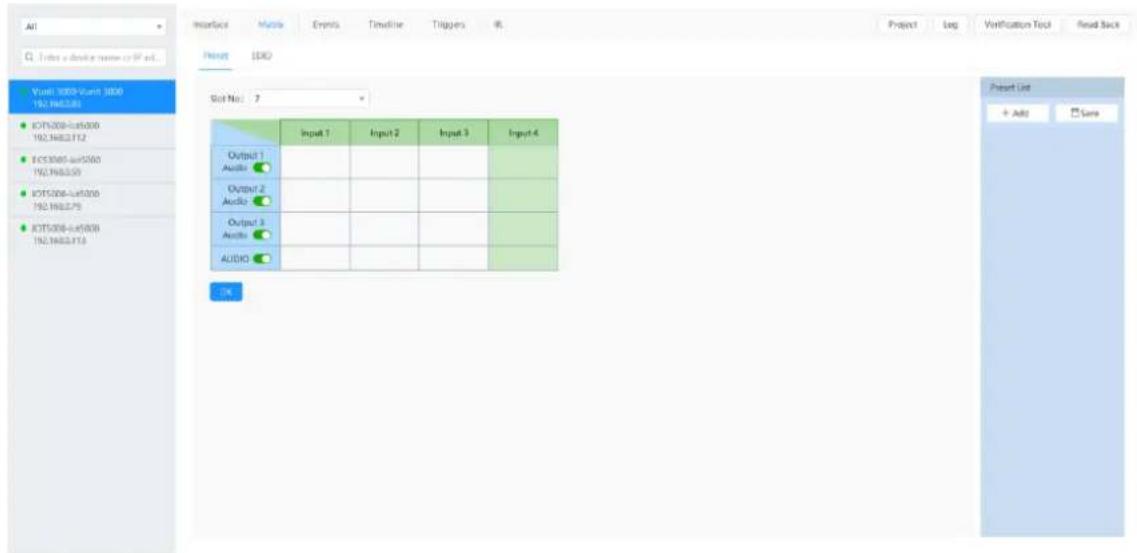
Step 4 Select the desired card slot number from the drop-down list next to Slot No.. The matrix configuration table will be automatically displayed.
Step 5 Click the matrix cells to relate or unrelated the inputs with the outputs.
For example, if output 2 is used to output the image of input 3, you need to click the matched cells of input 3 and output 2.
Figure 5-7 Output the image of input 3 via output 2
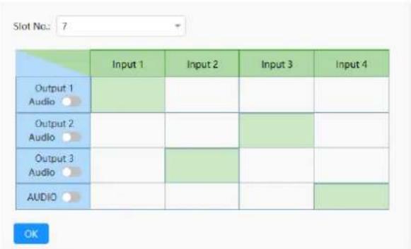
Step 6 Click the desired cell in the row of AUDIO to configure the output audio.
As shown in Figure 5-7, the input 4 cell in the row of AUDIO is selected and the audio of input 4 will be output.
Step 7 Click OK to complete the settings.
5.3.2 Configure EDID
Step 1 Click the Central Control Configuration tab to enter the corresponding page.
Step 2 Select the desired device from the device list on the left.
Step 3 Click the Matrix tab to enter the matrix configuration page.
Step 4 Click the EDID tab to enter the EDID settings page.
Figure 5-8 EDID settings
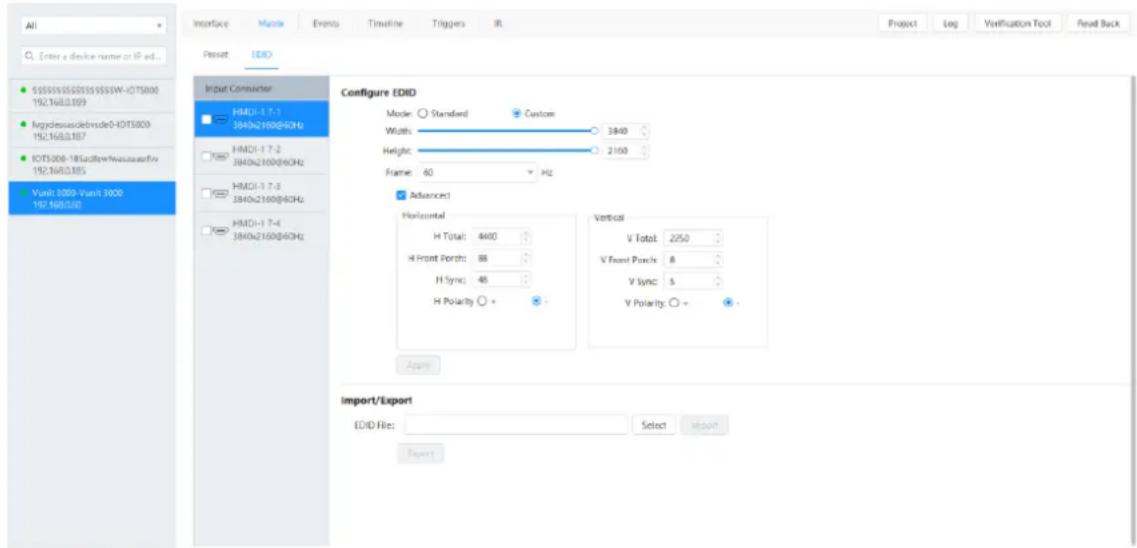
Step 5 Check the box in front of the desired input connector.
You can set the input connector resolution through the following three ways.
- Standard
Select an input resolution from the drop-down list next to Standard.
- Custom
Set the width, height and frame rate for the input connectors, and then click Apply to complete and apply the settings.
- Advanced
Under custom mode, you can select Advanced to enable the advanced EDID settings function. It is recommended personnel who are familiar with the EDID settings adopt this method. The parameters for advanced EDID settings are shown as follows.
Figure 5-9 Parameters for advanced EDID settings
- Import/Export
Export the configured resolution parameters file for future use, or import an existing EDID configuration file.
- Export EDID: Only the input or output resolution of a single connector can be exported.
- Import EDID: Import the configuration file to multiple connectors of the same type.
Step 6 Click Apply to complete and apply the settings.
5.3.3 Save Presets
After the input and output relationship is set successfully, you can save it as a preset for quick change and loading in the future. This enables seamless switching between input and output with one click.
Prerequisites
You have set the input and output relationship.
Operating Procedure
Step 1 In the preset list on the right, click Add and the system will automatically add a new preset.
Step 2 Hover the mouse over the added preset and click to change the preset name.
Other Operations
- Change the preset.
Click the desired preset to load it. In the matrix configuration table on the left, change the relationship between the input and output. Click Save to complete and apply the change.
- Turn on/off the audio.
In the matrix configuration table, toggle the switch next to Audio to turn on/off the audio.
5.4 Configure Events
Step 1 Click the Central Control Configuration tab to enter the corresponding page.
Step 2 Select the desired device from the device list on the left.
Step 3 Click the Events tab to enter the event configuration page.
Figure 5-10 Configure events
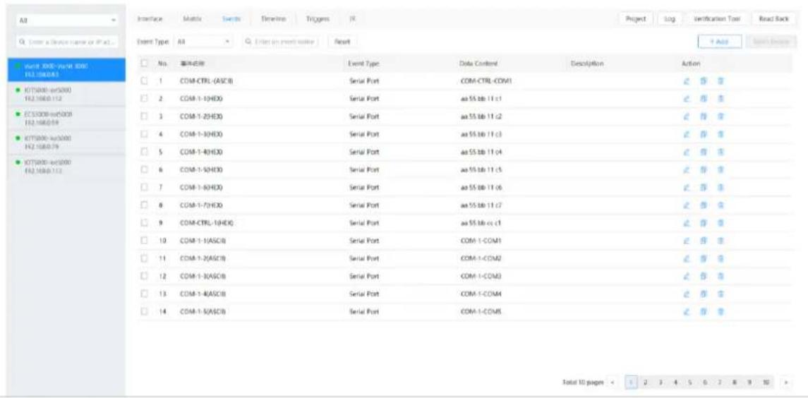
5.4.1 Configure Serial Port Events
Configure COM Events
When the backend device is controlled via COM protocol, you need to set the serial port mode to COM as described in 5.2.1 Configure Serial Port Parameters. Additionally, set the baud rate, data bits, stop bits and parity check according to the communication parameters of the backend device.
Step 1 On the event configuration page, click Add at the top right to open the new event adding window.
Figure 5-11 Add COM events
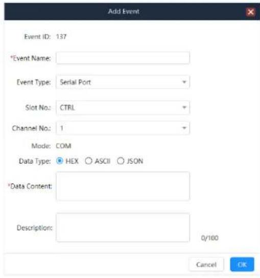
The event ID is generated automatically and cannot be edited. The ID cannot repeat and should increase in ascending order. After an event is deleted, the new event ID continues to increase based on the original order. When all the events are cleared, the event ID restarts from 1.
Step 2 Enter a name for the new event.
Step 3 Select Serial Port from the drop-down list next to Event Type.
Step 4 Select the slot number of the corresponding card matched with the added event.
CTRL: Main control card
Step 5 Select the channel number of the corresponding card matched with the added event.
Step 6 Select the data format of the control command next to Data Type.
- HEX: The control command is in hexadecimal format.
- ASCII: The control command is in text format.
- JSON: The control command is in .json format.
Step 7 Enter the control command in the text box next to Data Content.
Step 8 Enter the event description to provide clearer event details.
Step 9 Click OK to complete the adding.
Configure DMX Events
When the backend device is controlled via DMX protocol, you need to set the serial port mode to DMX as described in 5.2.1 Configure Serial Port Parameters.
Step 1 On the event configuration page, click Add at the top right to open the new event adding window.
Figure 5-12 Add DMX events
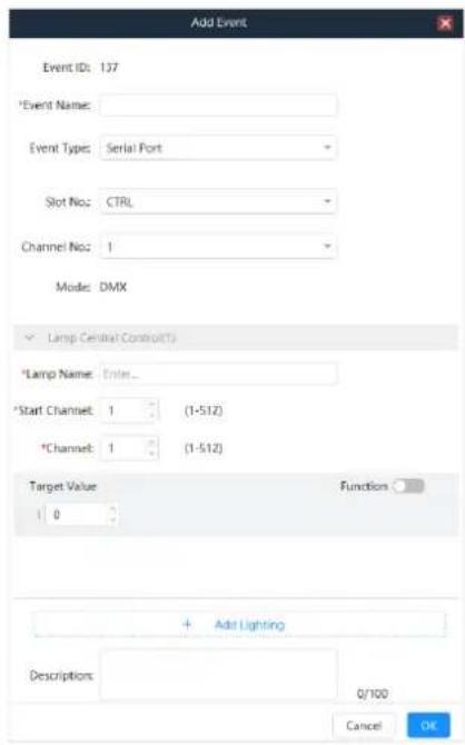
The event ID is generated automatically and cannot be edited. The ID cannot be repeated and should be increased in ascending order. After an event is deleted, the new event ID continues to increase based on the original order. When all the events are cleared, the event ID restarts from 1.
Step 2 Enter a name for the new event.
Step 3 Select Serial Port from the drop-down list next to Event Type.
Step 4 Select the slot number of the corresponding card matched with the added event.
Step 5 Select the channel number of the corresponding card matched with the added event.
Step 6 Below the Light area, configure the light according to the actual application.
• Light Name: The name of the controlled light
- Start Channel and Channels: Fill in the relevant values according to the specification of the controlled light.
- Target Value: Enter the command value for each channel. If you toggle the switch to on next to Function Name, you can also name each channel.
Note:
For different lights, please refer to the documentation that comes with the light to fill in the control parameters.
Step 7 If you want to control multiple lights which are under the control of the same light controller, click New Light and fill in the control command parameters.
Step 8 Enter the event description to provide clearer event details.
Step 9 Click OK to complete the adding.
Configure Modbus Events
When the backend device is controlled via Modbus protocol, you need to set the serial port mode to Modbus as described in 5.2.1 Configure Serial Port Parameters. Additionally, set the baud rate, data bits, stop bits and parity check according to the communication parameters of the backend device.
Step 1 On the event configuration page, click Add at the top right to open the new event adding window.
Figure 5-13 Add Modbus events
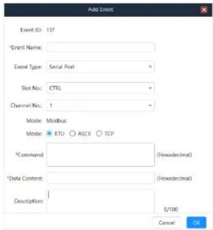
The event ID is generated automatically and cannot be edited. The ID cannot repeat and should increase in ascending order. After an event is deleted, the new event ID continues to increase based on the original order. When all the events are cleared, the event ID restarts from 1.
Step 2 Enter a name for the new event.
Step 3 Select Serial Port from the drop-down list next to Event Type.
Step 4 Select the slot number of the corresponding card matched with the added event.
Step 5 Select the channel number of the corresponding card matched with the added event.
Step 6 Select the control command mode supported by the backend device next to Mode. The supported options include RTU, ASCII and TCP.
Step 7 Enter the control command in the text box next to Command.
Step 8 Enter the control command in the text box next to Data Content.
The command and data content supports data in hexadecimal format.
Step 9 Enter the event description to provide clearer event details.
Step 10 Click OK to complete the adding.
5.4.2 Configure I/O Events
Step 1 On the event configuration page, click Add at the top right to open the new event adding window.
Figure 5-14 Add new events
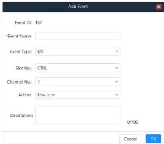
Step 2 Enter a name for the new event.
Step 3 Select I/O from the drop-down list next to Event Type.
Step 4 Select the slot number of the corresponding card matched with the added event.
Step 5 Select the channel number of the corresponding card matched with the added event.
Step 6 Select the response action that the controlled device supports.
The options include High Level and Low Level.
Step 7 Enter the event description to provide clearer event details.
Step 8 Click OK to complete the adding.
5.4.3 Configure IR Events
Prerequisites
You have added the infrared commands as described in 5.7 Configure IR Command Library.
Operating Procedure
Step 1 On the event configuration page, click Add at the top right to open the new event adding window.
Figure 5-15 Add new events
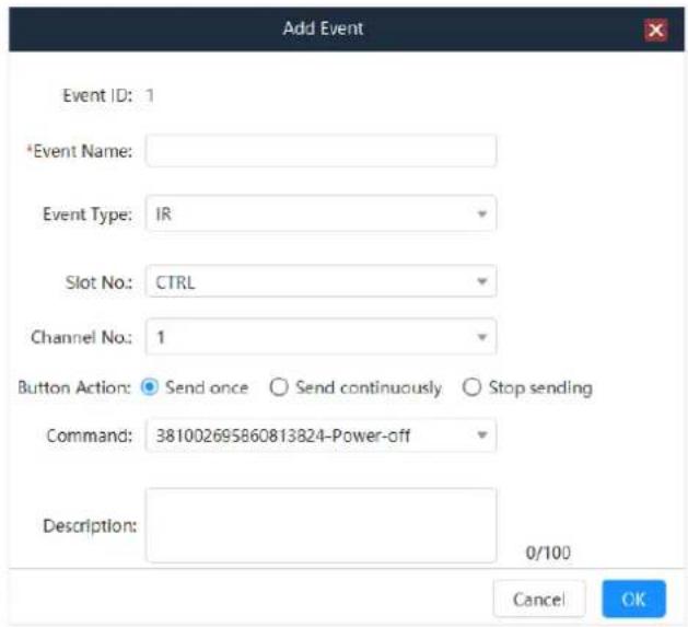
Step 2 Enter a name for the new event.
Step 3 Select IR from the drop-down list next to Event Type.
Step 4 Select the slot number where the corresponding card matched with the added event is installed.
Step 5 Select the slot number of the corresponding card matched with the added event.
Step 6 Select the command sending information of the IR control button next to Button Action.
The supported options include Send once, Send continuously and Stop sending.
- Send once: For each operation, the system will send the command once.
- Send continuously: The system sends the command automatically and continuously.
- Stop sending: Working with Send continuously, you can stop sending the command continuously.
Step 7 Select the added infrared command from the drop-down list next to Command.
Step 8 Enter the event description to provide clearer event details.
Step 9 Click OK to complete the adding.
5.4.4 Configure Relay Events
Step 1 On the event configuration page, click Add at the top right to open the new event adding window.
Figure 5-16 Add new events
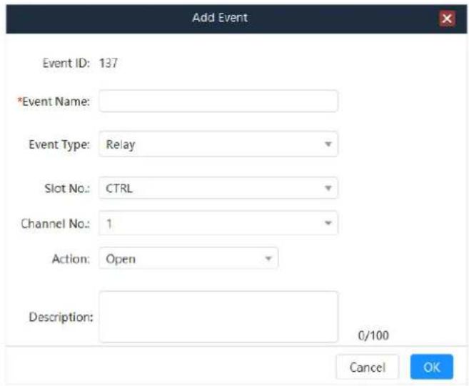
Step 2 Enter a name for the new event.
Step 3 Select Relay from the drop-down list next to Event Type.
Step 4 Select the slot number of the corresponding card matched with the added event.
Step 5 Select the channel number of the corresponding card matched with the added event.
Step 6 Select the Relay status from drop-down list next to Response Action.
The supported options include Close, Open and Delay Open.
When Delay Open is selected, you need to set the delay duration. After the set duration, the delay will be closed.
Step 7 Enter the event description to provide clearer event details.
Step 8 Click OK to complete the adding.
5.4.5 Configure Delay Events
When there are multiple commands in the trigger, you can add a delay interval.
Step 1 On the event configuration page, click Add at the top right to open the new event adding window.
Figure 5-17 Add new events
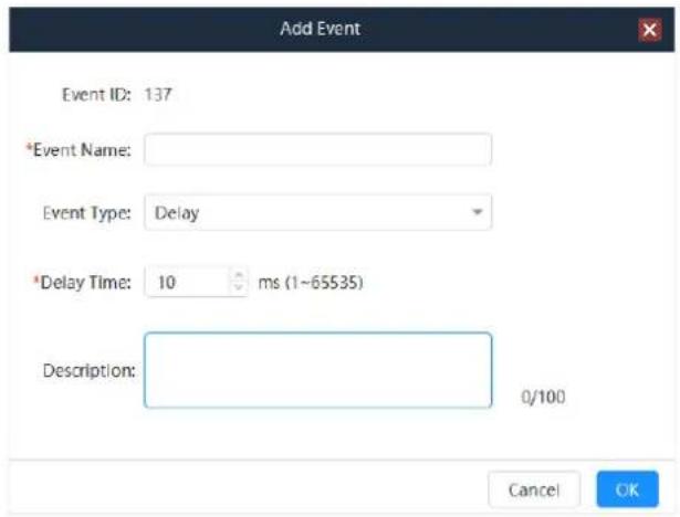
Step 2 Enter a name for the new event.
Step 3 Select Delay from the drop-down list next to Event Type.
Step 4 Enter the delay time ranging from 1 to 65535. The unit is ms.
Step 5 Enter the event description to provide clearer event details.
Step 6 Click OK to complete the adding.
5.4.6 Configure Ethernet Port Events
Step 1 On the event configuration page, click Add at the top right to open the new event adding window.
Figure 5-18 Add new events
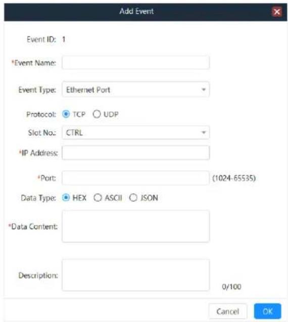
Step 2 Enter a name for the new event.
Step 3 Select Ethernet Port from the drop-down list next to Event Type.
Step 4 Select the transmission protocol.
The supported options include TCP and UDP.
Step 5 Select the slot number of the corresponding card matched with the added event.
Step 6 Enter the IP address of the controlled device.
Step 7 Enter the port number used for transmission with the controlled end. The value ranges from 1024 to 65535, but 8080 is unavailable.
Step 8 Select the data format of the control command next to Data Type.
- HEX: The control command is in hexadecimal format.
- ASCII: The control command is in text format.
- JSON: The control command is in .json format.
Step 9 Enter the control command in the text box next to Data Content.
Step 10 Enter the event description to provide clearer event details.
Step 11 Click OK to complete the adding.
5.4.7 Configure CAN Events
Step 1 On the event configuration page, click Add at the top right to open the new event adding window.
Figure 5-19 Add new events
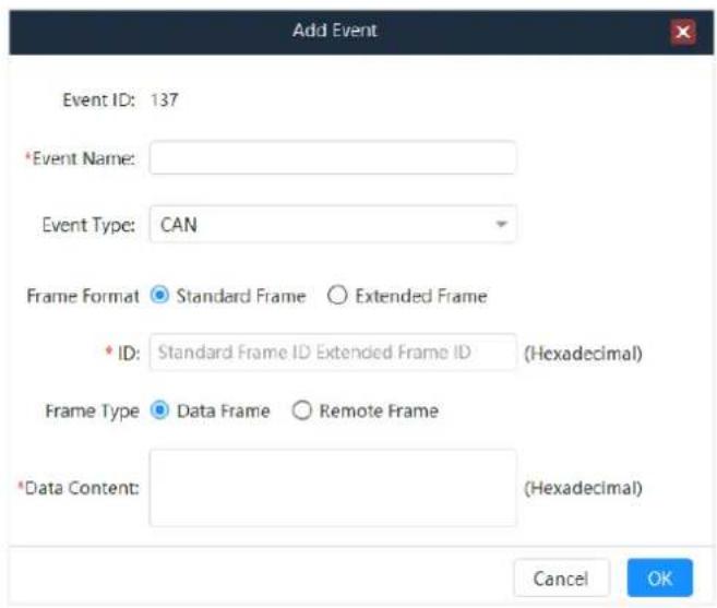
Step 2 Enter a name for the new event.
Step 3 Select CAN from the drop-down list next to Event Type.
Step 4 Select the frame format of the Ethernet port transmission protocol.
The supported options include Standard Frame and Extended Frame.
Step 5 Enter the standard frame ID or extended frame ID.
The hexadecimal format is supported.
Step 6 Select the frame type of CAN protocol.
The supported options include Data Frame and Remote Frame.
- Data Frame: The frame used for data transmission from the sending unit to the receiving unit
- Remote Frame: The frame used for data requests from the receiving unit to the sending unit with the same ID as the receiving unit
Step 7 Enter the control command in the text box next to Data Content.
Step 8 Click OK to complete the adding.
5.4.8 Other Operations
- Change the event.
In the event list, select the desired event and click 🔒 in the column of Action to open the event editing window where you can edit the event. Click OK to complete the editing.
- Delete the event.
In the event list, select the desired event and click 📄 in the column of Action to delete the selected event.
The event used in triggers cannot be deleted.
- Copy the event.
In the event list, select the desired event and click in the column of Action. The system will copy the event and open the event editing window where you can edit the event. Click OK to complete the copy.
- Search and filter the event.
- On the event configuration page, enter the event name to search the desired event. The fuzzy search is supported.
- Select the desired event type from the drop-down list next to Event Type. You can view the added events according to the selected event type.
5.5 Configure Timeline
The Vunit 3000 supports the automatic execution of tasks within a predetermined timeline.
Prerequisites
You have configured the event as described in 5.4 Configure Events.
Operating Procedure
Step 1 On the Central Control Configuration page, click the Timeline tab to enter the timeline configuration page.
Figure 5-20 Configure timeline
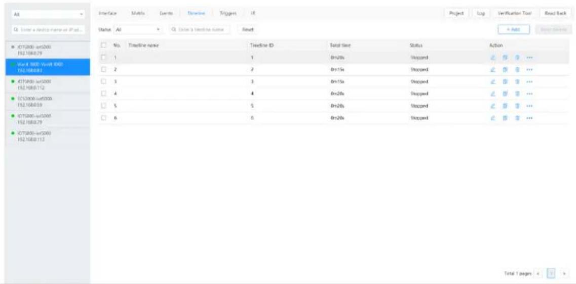
Step 2 Click Add at the top right to open the new timeline adding window.
Figure 5-21 Add timeline and task
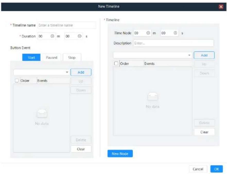
Step 3 Enter a timeline name for easy task triggering in the future.
Step 4 Set the duration for the timeline task.
Step 5 Configure the tasks for the button events individually. The button events include Start, Pause and Stop.
- Start: When a start task is triggered, the task configured to Start will be automatically executed and the timer will be automatically started.
- Pause: When a pause task is triggered, the task configured to Paused will be automatically executed and the timer will be paused.
- Stop: When a stop task is triggered, the task configured to Stop will be automatically executed and the timer will be stopped.
The following operations take the start task as an example to illustrate.
- Click the Start tab to enter the event configuration page.
- Select the desired event from the drop-down list next to Add.
- Click Add to complete the adding.
- Select other events and click Add to add them.
After the events are added successfully, select Start from the drop-down list next to Status on the timeline page. The system will automatically execute the events according to the selected task sequence.
- Up: Move the selected event up.
- Down: Move the selected event down.
- Delete: Delete the selected event. The deleted event will not be executed.
– Clear: Clear all the added events.
Step 6 Set the time node.
Configure the key time nodes within the timeline duration and automatically execute the task in the key time node.
- Set the time node after the task is executed.
For example, if the time node is set to 5 minutes and 30 seconds, it means that the time node task will be executed after the timeline is executed for 5 minutes and 30 seconds.
- Enter the task description in the text box, which helps to know the task.
- Select the desired event from the drop-down list next to Add.
- Click Add to complete the adding.
- Select other events and click Add to add them.
Select the added event and adjust the execution sequence by selecting Up, Down or Delete.
Step 7 Click New Node to add more time nodes.
After a new time node is added successfully, configure the task for the time node following the operations in Step 6.
Step 8 Click OK to complete the adding.
Figure 5-22 Timeline tasks
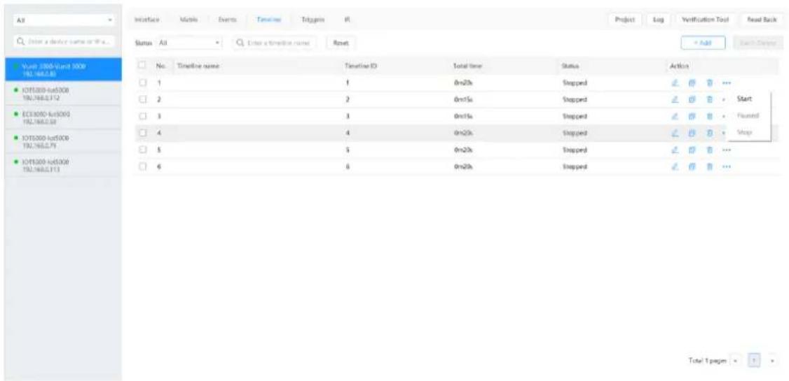
Step 9 Click ... in the column of Action and to expand the menu pane. The options include Start, Pause and Stop.
Other operations:
• : Edit the selected timeline task.
• : Copy the selected timeline task as a new task.
- : Delete the selected timeline task.
5.6 Configure Triggers
The Vunit 3000 supports the conditional and scheduled triggers.
- Conditional trigger: Configure the trigger condition. When the trigger condition is met, the system will automatically execute the added events in order.
- Scheduled trigger: Configure the execution time. When the set time is reached, the system will automatically execute the added events in order.
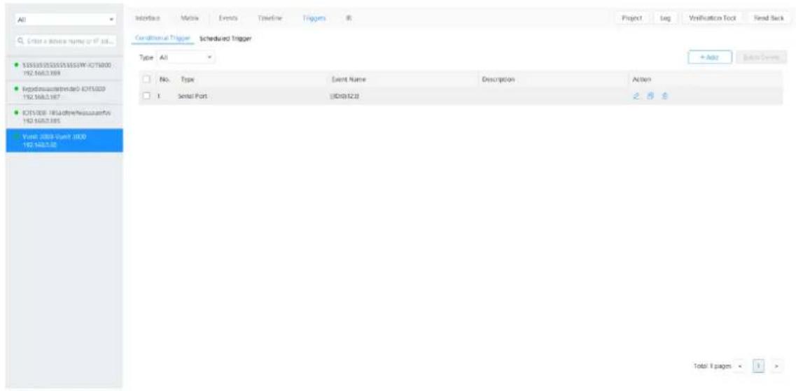
On the Central Control Configuration page, click Triggers to enter the trigger configuration page.
Figure 5-23 Triggers
5.6.1 Configure Conditional Triggers
Prerequisites
You have added the event or matrix preset.
Operating Procedure
Step 1 Click the Conditional Trigger tab to enter the conditional trigger configuration page.
Step 2 Click Add at the top right to open the conditional trigger adding window.
Figure 5-24 Conditional triggers
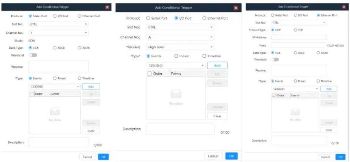
Step 3 Select the desired protocol. The supported options include Serial Port, I/O Port and Ethernet Port.
- Serial Port: Receive the serial command sent by the trigger end. You need to configure the slot number of the serial port, channel number of the corresponding card where the serial port is located, protocol type of the trigger command and received command information.
- I/O Port: Receive the high and low level signals sent by the trigger end. You need to configure the slot number of the I/O port, channel number of the corresponding card where the I/O port is located and received command information.
- Ethernet Port: Receive the network command sent by the trigger end. You need to configure the slot number of the Ethernet port, transmission protocol, IP address of the trigger end, communication port number, protocol type of the trigger command and received command information.
Step 4 (Optional) Set whether the command is triggered by a threshold.
- If the command is trigger by a threshold, toggle the switch to on next to Threshold.
- Enter the received command in the text box next to Receive. The variables in the command must be replaced with #.
Step 5 Configure the command processing information.
- Select the command processing type. The supported options include Events, Preset and Timeline.
- Select the desired event or preset from the event list or preset list.
- Click Add to add the selected event or preset to the command list.
-
In the command list, select an event or preset and click Up or Down to adjust the sequence of the selected event or preset.
-
Click Delete to delete the selected event or preset.
-
Click Clear to clear all the selected events or presets.
-
If the command processing type is set to Timeline, you need to set the control mode of the timeline for the third party. The supported options include Start, Pause and Stop.
Step 6 Enter the detailed descriptions for the added trigger.
Step 7 Click OK to complete the adding.
5.6.2 Configure Scheduled Triggers
Prerequisites
You have added the event or matrix preset.
Operating Procedure
Step 1 Click the Schedule Trigger tab to enter the schedule trigger configuration page.
Step 2 Click Add at the top right to open the scheduled trigger adding window.
Figure 5-25 Scheduled triggers
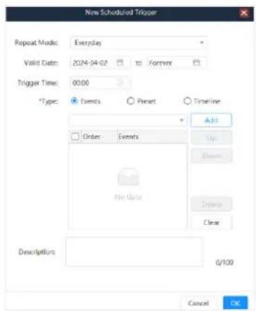
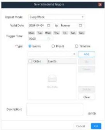
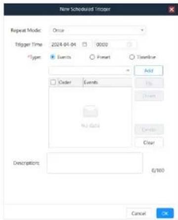
Step 3 Select the desired repeat mode. The supported options include Everyday, Every Week and Once.
- Everyday: Execute the added event or preset everyday. You need to set the start and end dates.
- Every Week: Execute the added event or preset every week. You need to set the start and end dates.
- Once: You need to set the execution date and time to execute the added event or preset.
Step 4 Set the trigger event.
- When Everyday is selected, you need to set the execution start time.
- When Every Week is selected, you need to set the execution day of the week and start time.
- When Once is selected, you need to set the date and start time.
Step 5 Configure the command processing information.
- Select the command processing type. The supported options include Event, Preset and Timeline.
- Select the desired event or preset from the event list or preset list.
- Click Add to add the selected event or preset to the command list.
- In the command list, select an event or preset and click Up or Down on the right to adjust the sequence of the selected event or preset.
- Click Delete to delete the selected event or preset.
- Click Clear to clear all the selected events or presets.
Step 6 Enter the detailed descriptions for the added trigger.
Step 7 Click OK to complete the adding.
5.6.3 Other Operations
- Change the trigger.
In the trigger list, select the desired trigger and click 🔒 in the column of Action to open the trigger editing window where you can edit the trigger. Click OK to complete the editing.
- Delete the trigger.
- Delete single trigger: In the trigger list, select the desired trigger and click in the column of Action to delete the selected trigger.
- Batch delete: In the trigger list, check the boxes in front of the desired triggers and click Batch Delete at the top right to delete all the selected triggers.
- Copy the trigger.
In the trigger list, select the desired trigger and click in the column of Action. The system will copy the trigger and open the trigger editing window where you can edit the trigger. Click OK to complete the copy.
- Filter the trigger.
- Filter the conditional trigger: Select the desired event type from the drop-down list next to Type to filter the trigger.
- Filter the scheduled trigger: Set the desired repeat mode or valid date to filter the trigger.
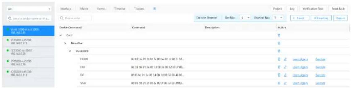
5.7 Configure IR Command Library
Add the desired controlled devices to the Vunit 3000 so that you can select the corresponding execution command when adding the IR event.
On the Central Control Configuration page, click IR to enter the corresponding page.
Figure 5-26 IR command library
5.7.1 Configure IR Device Levels
Configure the device information controlled by IR.
Step 1 On the IR page, click Level at the top right to open the level adding window.
Figure 5-27 Add levels
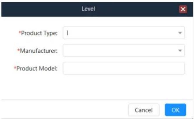
Step 2 Enter the desired product type, such as the air conditioning or television.
Step 3 Enter the product manufacturer for easy categorizing.
Step 4 Enter the product model.
Step 5 Click OK to complete the level adding.
Note:
Once the product type and manufacturer are added, you can simply select the added one from the dropdown list for future use.
5.7.2 Configure IR Learning
Prerequisites
• You have added the level.
• You have obtained the remote control.
Operating Procedure
Step 1 On the IR page, click IR Learning at the top right to open the IR learning window.
Figure 5-28 IR learning
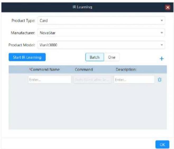
Step 2 Select the product type, manufacturer and product model.
Step 3 Click to add the desired command.
Step 4 Enter a name for the added command.
Enter the command descriptions to better obtain the command information.
Step 5 Click Start IR Learning and the device will enter the learning mode.
Step 6 Aim the remote control matched with the selected product model at the Vunit 3000 and press the buttons matched with the commands. The system will automatically learn the IR commands one by one and display them in the text boxes below Command.
Figure 5-29 Command learning
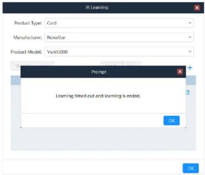
Step 7 Click Complete to complete the learning.
5.7.3 Other Operations
- Change the IR command name.
Only IR command name can be changed via the following two ways.
- After the command learning is completed, enter a new name in the text box below Command Name in the IR learning window.
- On the IR page, select the desired IR command and click 🔒 in the column of Action to open the command editing window where you can change the command name.
- Delete the IR command.
On the IR page, select the desired IR command and click 📋 in the column of Action to delete the selected IR command.
You cannot delete the IR command used in the event.
- Learn the IR command again.
On the IR page, click Learn Again in the column of Action open the IR learning window. Press the buttons on the remote control to learn the IR commands again.
- Test the IR command.
After the IR learning is completed and the controlled device is connected, click Execute in the column of Action to test whether the current command is correct.
- Export the IR command.
After the IR command is added, click Export at the top right to export the command information to your local device.
5.8 Project Files
5.8.1 Import Project Files
After the device is connected, you can manually add the event, trigger and perform IR learning. You can also quickly add the configuration information by importing the project file.
Step 1 On the Central Control Configuration page, click Project at the top right to open the corresponding window.
Figure 5-30 Import project files
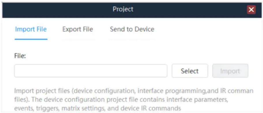
Step 2 Click Select to select the desired project file and click Open.
Step 3 Click Import to import the selected file to the device.
After the project file is imported successfully, the device will automatically restart.
5.8.2 Export Project Files
When the device configuration is complete, you can export the configuration information as a project file and save it to your computer for quick configuration in the future.
Step 1 On the Central Control Configuration page, click Project at the top right to open the corresponding window.
Step 2 Click Export File to open the project file exporting window.
Figure 5-31 Export project files
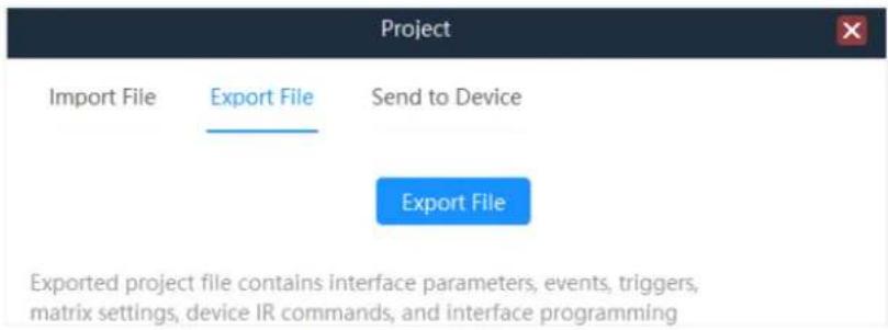
Step 3 Click Export and select the save location.
Step 4 Click OK to complete the exporting.
5.8.3 Send to Device
After the device configuration is complete, you can save the configuration information as a project file and also send the configuration information to other Vunit 3000 devices via this function.
Step 1 On the Central Control Configuration page, click Project at the top right to open the corresponding window.
Step 2 Click Send to Device to open the corresponding window.
Figure 5-32 Send to device
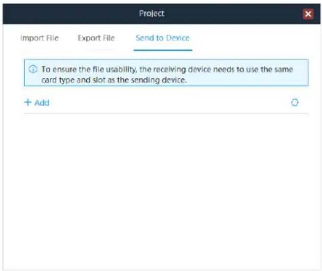
Step 3 Click Add and enter the IP information of the desired control processor. Click OK to add it to the control processor list.
Step 4 Click to send the configuration information to the selected control processor.
5.9 Manage Logs
In the log management window, you can export the device configuration logs, which can be used by our technical support staff or developers to analyze device problems.
6 Language
Change the UI language. BCTools supports English and Simplified Chinese.
Copyright © 2024 Xi'an NovaStar Tech Co., Ltd. All Rights Reserved.
No part of this document may be copied, reproduced, extracted or transmitted in any form or by any means without the prior written consent of Xi'an NovaStar Tech Co., Ltd.
Trademark
NOVA STAR is a trademark of Xi'an NovaStar Tech Co., Ltd.
Statement
Thank you for choosing NovaStar's product. This document is intended to help you understand and use the product. For accuracy and reliability, NovaStar may make improvements and/or changes to this document at any time and without notice. If you experience any problems in use or have any suggestions, please contact us via the contact information given in this document. We will do our best to solve any issues, as well as evaluate and implement any suggestions.
- Professional Control Processor
- Contents
- Change History......i
- Control Connections
- Control Connections
- Software Installation
- Obtaining
- Installation
- Menu Operations
- Operating Instructions:
- - Knob:
- Switch Screen
- Menu Functions
- Return to Home Screen
- Network Settings
- Firmware Version
- Advanced Settings
- Serial Port Settings
- I/O Settings
- IR Settings
- USB Impot/Export
- Firmware Update
- Factory Reset
- Language
- About Us
- Device Connections
- Connect Devices
- Prerequisites
- Operating Procedure
- Notes:
- Change IP Information
- Batch Change IP Information
- Configure Devices
- Change Device Names
- Change Single Device Name
- Batch Change Device Names
- Update Firmware
- Update Single Device
- Batch Update
- Synchronize Device Clocks
- Run Diagnostics
- Factory Reset
- Configure Central Control Devices
- Read Back Device Information
- Configure Connector Parameters
- Configure Serial Port Parameters
- Configure I/O Modes
- Configure CAN Modes
- Configure Matrices
- Set Input and Output Relationships
- Configure EDID
- Save Presets
- Other Operations
- Configure Events
- Configure Serial Port Events
- Configure COM Events
- Configure DMX Events
- Note:
- Configure Modbus Events
- Configure I/O Events
- Configure IR Events
- Configure Relay Events
- Configure Delay Events
- Configure Ethernet Port Events
- Configure CAN Events
- Other Operations
- Configure Timeline
- Configure Triggers
- Configure Conditional Triggers
- Step 3 Select the desired protocol. The supported options include Serial Port, I/O Port and Ethernet Port.
- Configure Scheduled Triggers
- Other Operations
- Configure IR Command Library
- Configure IR Device Levels
- Configure IR Learning
- Other Operations
- Project Files
- Import Project Files
- Export Project Files
- Send to Device
- Manage Logs
- Language
- Trademark
- Statement
Brand : NovaStar
Model : Vunit 3000
Category : Processor