J6 - Processor NovaStar - Free user manual and instructions
Find the device manual for free J6 NovaStar in PDF.

| Product Type | Video Processor / Seamless Switcher |
| Brand | NovaStar |
| Model | J6 |
| Dimensions (W × D × H) | 482.6 mm × 379.5 mm × 95.5 mm |
| Net Weight | 5.3 kg |
| Gross Weight | 15 kg |
| Power Supply | AC 100-240 V, 50/60 Hz, 2.1 A |
| Power Consumption | 50 W |
| Input Connectors | 1×DP 1.1, 1×3G-SDI, 1×HDMI 1.3, 1×DVI, plus optional DP/DVI/HDMI/SDI (up to 8 inputs) |
| Output Connectors | 4 groups of DVI (main+backup), 1×HDMI monitor output |
| Max Input Resolution | 4K×2K@30Hz (DP/HDMI 1.4) |
| Max Output Loading Capacity | Up to 9,200,000 pixels (Splicer mode), up to 4,000,000 pixels (Switcher mode) |
| Number of Layers | Up to 6 layers |
| System Modes | Splicer and Switcher |
| Control Interfaces | Front panel, USB (Type-B), Ethernet, C1 event controller, V-Can software |
| Transition Effects | Fade and Cut with adjustable duration |
| Presets | Up to 32 presets |
| BKG (Background) | Image capture, pure color, up to 6 BKG images |
| Operating Temperature | -20°C to +70°C |
| Accessories Included | Power cord, Ethernet cable, DVI cables, USB cable, HDMI cable, HDMI-to-DVI cable, mini DP to DP cable, flight case, user manual |
Frequently Asked Questions - J6 NovaStar
User questions about J6 NovaStar
0 question about this device. Answer the ones you know or ask your own.
Ask a new question about this device
Download the instructions for your Processor in PDF format for free! Find your manual J6 - NovaStar and take your electronic device back in hand. On this page are published all the documents necessary for the use of your device. J6 by NovaStar.
USER MANUAL J6 NovaStar
2.1 Front Panel 3
2.2 Rear Panel....4
2.3 Dimensions 6
3 Applications....7
4 Menu Operations....8
4.1 Operation Instructions....8
4.2 Home Screen....8
4.3 Screen Settings 10
4.3.1 Output Mode 10
4.3.2 Screen Layout....11
4.3.3 Output Settings 11
4.3.4 Output Connector Settings....12
4.4 Layer Settings.... 12
4.4.1 Layer Layout 12
4.4.2 BKG Settings....13
4.4.3 Layer Settings....14
4.5 Preset Settings 15
4.6 Input Settings....16
4.7 Display Control 16
4.8 MVR Settings....18
4.9 Advanced Settings....18
4.9.1 System Mode....19
4.9.2 Sync Mode 19
4.9.3 AUX....19
4.9.4 Fn Settings....20
4.9.5 Go Homepage....21
4.9.6 Factory Reset.... 21
4.9.7 HDCP....21
4.9.8 RGB Color Range Converting....21
4.9.9 Hardware Version....22
4.9.10 Self-Test 22
4.9.11 About Us.... 22
4.10 Communication Settings....22
4.11 Language 23
5 V-Can Control....24
6 C1 Control 25
7 Troubleshooting.... 27
8 Specifications....28
1 Overview
1.1 Introduction
The J6 is a NovaStar's high-performance seamless switcher that integrates video processing, screen mosaic, transition effects and multi-screen display capabilities. The J6 offers powerful video signal receiving and processing abilities and supports up to 8 inputs with the resolution up to 4K×2K@30Hz and 6 layers. In addition, this product supports two system modes: Splicer and Switcher. When it is in Splicer mode, a maximum of 4 DVI output connectors can be used together for output, which can realize an up to 8KK loading capacity of each J6 unit. When it is in Switcher mode, a maximum of 2 DVI output connectors can be used together for output, which can realize an up to 4KK loading capacity of each J6 unit.
Based on a powerful FPGA platform, the J6 supports input and output EDID management and color adjustment, seamless transition on a variety of input sources, as well as fade and other transition effects, bringing you a more flexible and rich visual experience.
What's more, the J6 is equipped with NovaStar's smart control software V-Can and C1 event controller, allowing for a rich screen mosaic effect via V-Can, C1 or front panel operations. With excellent image quality, ultra-large loading capacity and flexible operation modes, the J6 can be widely used in conference reports, exhibition centers, stage control and other application scenarios.
1.2 Features
● Industry-standard input connectors
- DVI connector: 1920×1080@60Hz input
- HDMI 1.3 connector: 1920×1080@60Hz input
- 3G-SDI connector: 1920×1080@60Hz input
- DP 1.1 connector: 4K×2K@30Hz input
-
HDMI 1.4 connector: 4K×2K@30Hz input
-
4 groups (2 connectors in each group) of DVI output connectors of a single J6 unit for mosaic output Each group includes a main connector and a backup connector. A maximum of 4 connectors can be used for mosaic output. The mosaic layout can be 4 × 1 , 1 × 4 or 2 × 2 . The maximum loading capacity can reach 9,200,000 pixels and the maximum mosaic width can be up to 15360 pixels.
- Dual system modes
Supports both Splicer and Switcher modes, which can meet different application requirements.
● Multiple layer display
Supports up to 6x 4K×2K layers that can be positioned freely and cross connector output. Supports layer border settings.
● HDMI connector dedicated for output monitoring
- Supports monitoring of a single input source, PVW or PGM.
- Supports mixed monitoring of all input sources, PVW and PGM.
- Supports displaying of input resolution and refresh rate.
- Display control function
Makes the screen fade to black or freeze the screen by simply clicking one button.
• EDID management
Supports input resolution management on DVI, HDMI and DP connectors.
- Transition effects
In Splicer mode, the device supports the setting of transition effect for source and preset switching. In Switcher mode, the device supports the setting of Take effect and effect duration.
- BKG capturing
Supports the capturing of input source and PGM, and the captured image can be used as BKG.
● BKG image and pure color BKG
Supports both image BKG and pure color BKG. Up to 6 BKG images are supported.
- Adjustable input color, layer color and output color
- Preset management
Up to 10 presets are supported and the preset can be loaded simply by clicking one button.
● Layer layout management
The device is built-in with 7 layer layouts. You can load one of the layer layouts to quickly lay out the layers.
● Multiple operation modes
The device can be controlled via its front panel, the smart control software V-Can or C1 event controller.
● Multiple J6 units controlled by one C1 unit
You can perform operations, such as FTB, freeze or Take operation, to multiple J6 units on the C1.
- AUX
In Switcher mode, the device supports the AUX function.
- Intuitive LCD screen and clear button indicators on front panel, simplifying system control operations
2 Appearance
2.1 Front Panel
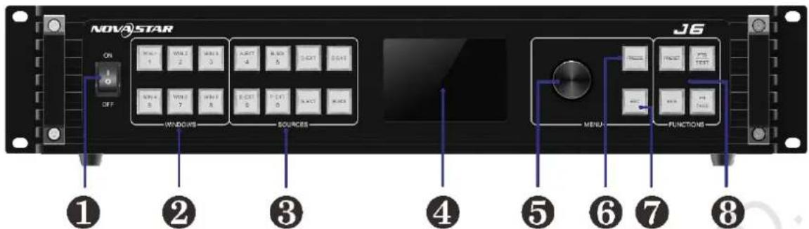
| No. | Button | Description |
| 1 | ON/OFF button | Press ON to power on the device.Press OFF to power off the device. |
| 2 | Layer buttons | Open or close a layer, and show the layer status.Status LEDs:On: The layer is open, and the input source is accessed normally.Dim: The layer is open, but the input source is abnormal.Off: The layer is not opened.Flashing: The layer is being edited.On the home screen, hold down the layer button for 2s or longer to close the opened layer. |
| 3 | Input source buttons | Switch the layer input source and show the input source status.Status LEDs:On: The input source is accessed and in normal use.Dim: The input source is accessed but not in use.Off: The input source is not accessed or the source signal is abnormal. |
| 4 | LCD screen | Display the device menus, submenus and messages. |
| 5 | Knob | On the home screen, press the knob to enter the operation menu screen.On the operation menu screen, rotate the knob to select a menu item, and press the knob to confirm the selection or enter the submenu.When a menu item with parameters is selected, rotate the knob to adjust the parameters. Please note that after adjustment, you need to press the knob again to confirm the adjustment. |
| 6 | Freeze button | Freeze or unfreeze the output image.Status LEDs:On: The freeze function is enabled.Off: The freeze function is disabled. |
| 7 | ESC button | Press the button to exit the current menu or cancel the operation. |
| 8 | Function buttons | PRESET: Enter the preset menu.BKG: Enable or disable the BKG function.FTB/TEST: Press the button to make the screen fade to black and press the button again to exit the FTB mode. Hold down the button for 2s or longer toenter the test pattern menu.FN/TAKE: The function of this button varies in different system modes (Splicer and Switcher).In Splicer mode, press the button to enter the menu of the function that has been customized for Fn button. Hold down the button to enter the FN settings menu.In Switcher mode, press the button to send PVW to PGM. |
2.2 Rear Panel
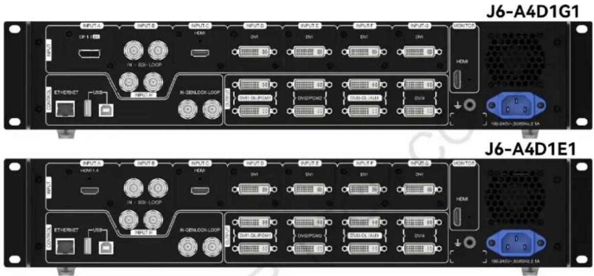
Notes:
- The J6 provides two default configurations that differ in Input-F and Input-G connectors on the rear panel.
- DP 1.1 and HDMI 1.4 connectors support at most 2 layers. Other connectors support at most 6 layers.
| Input | ||
| No. | Connector | Description |
| INPUT-A | DP 1.1 | Input resolution up to 3840×2160@30Hz and custom EDID supported HDCP 1.3 compliantInterchangeable with HDMI 1.4 input card (Input resolution up to 3840×2160@30Hz and custom EDID supported, HDCP 1.4 compliant) Does not support interlaced signal inputs. |
| INPUT-B | 3G-SDI | Input resolution up to 1920×1080@60HzLoop through functionInterlaced signal processing supportedDoes not support input resolution and bit depth settings |
| INPUT-C | HDMI 1.3 | Input resolution up to 1920×1080@60Hz and custom EDID supported HDCP 1.4 compliantInterlaced signal processing supportedInterchangeable with DVI or 3G-SDI input card |
| INPUT-D | DVI | Input resolution up to 1920×1080@60Hz, other VESA standard resolutions and custom EDID supported HDCP 1.4 compliantInterchangeable with HDMI 1.3 or 3G-SDI input cardDoes not support interlaced signal inputs |
| INPUT-E | ||
| INPUT-F | - | The J6 has two default versions |
| INPUT-G | DP 1.1 / DVI | • Version I: INPUT-G is DP 1.1 input card that supports up to 3840×2160@30Hz video source input and custom EDID. When it is changed to HDMI 1.4 input card, the INPUT-F is unavailable• Version II: INPUT-F and INPUT-G are DVI input cards that support up to 1920×1080@60Hz and other VESA-standard compliant video source inputs and custom EDID. The two connectors both can be changed to HDMI 1.3 or 3G-SDI input card |
| INPUT-H | 3G-SDI | Input resolution up to 1920×1080@60HzLoop through functionInterlaced signal processing supported |
| Output | ||
| No. | Connector | Description |
| DVI | 8 | 4 groups (2 connectors in each group) of DVI output connectors can be used for mosaic output.Each group includes a main connector and a backup connector.The J6 supports dual-link DVI output mode. When the output is set to dual-link mode, DVI 1 and DVI 3 are used as output connectors, while DVI 2 and DVI 4 are unavailable.In Splicer mode, DVI 3 can be used for AUX. |
| MONITOR | 1 | An HDMI connector dedicated for monitoring all input sources, a single input source, PVW and PGM. |
| Control | ||
| No. | Connector | Description |
| ETHERNET | 1 | Communicate to the control PC or connect to the network. |
| USB (Type-B) | 1 | Connect to the control PC for device control. |
| USB (Type-A) | 1 | A reserved connector |
| Overall Specifications | ||
| No. | Connector | Description |
| Power | 1 | AC100-240V~50/60Hz |
2.3 Dimensions
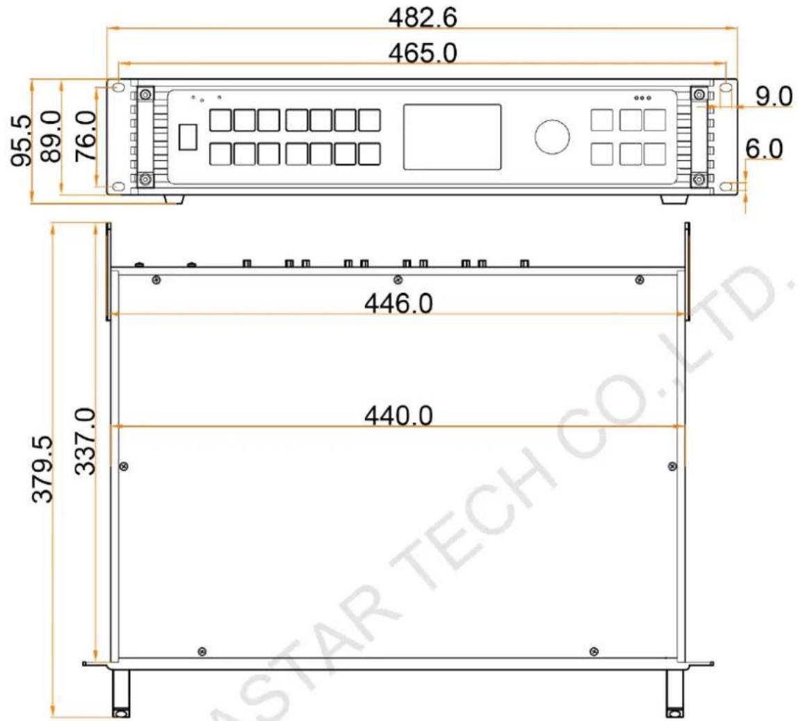
Tolerance: ±0.3 Unit: mm
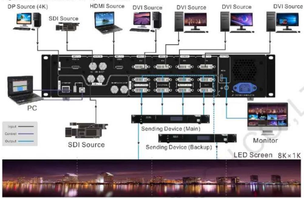
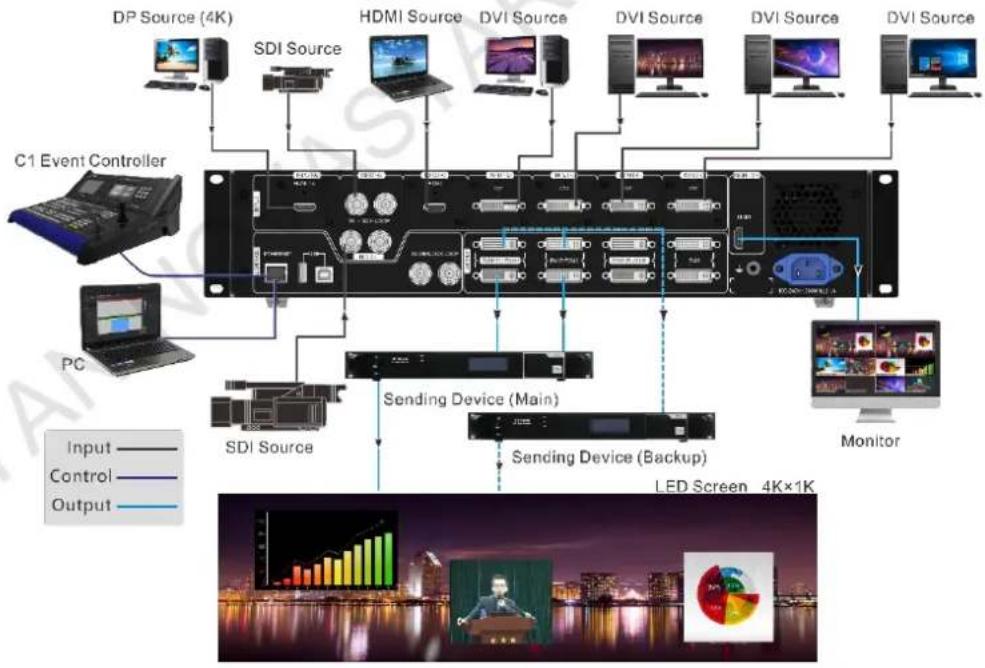
3 Applications
The J6 supports dual system modes: Splicer and Switcher. The connections for two modes are shown in Figure 3-1 and Figure 3-2.
Figure 3-1 Connections for Splicer mode
flowchart
graph TD
    A["DP Source (4K)"] --> B["SDI Source"]
    B --> C["PC"]
    C --> D["SDI Source"]
    D --> E["HDMI Source"]
    E --> F["DVI Source"]
    F --> G["DVI Source"]
    G --> H["DVI Source"]
    H --> I["DVI Source"]
    I --> J["DVI Source"]
    J --> K["Monitor"]
    K --> L["LED Screen 8K×1K"]
    style A fill:#f9f,stroke:#333
    style B fill:#ccf,stroke:#333
    style C fill:#cfc,stroke:#333
    style D fill:#fcc,stroke:#333
    style E fill:#cff,stroke:#333
    style F fill:#ffc,stroke:#333
    style G fill:#cfc,stroke:#333
    style H fill:#cfc,stroke:#333
    style I fill:#cfc,stroke:#333
    style J fill:#cfc,stroke:#333
    style K fill:#fcc,stroke:#333
    style L fill:#fff,stroke:#333
Figure 3-2 Connections for Switcher mode
flowchart
graph TD
    A["DP Source (4K)"] --> B["SDI Source"]
    B --> C["HDMI Source"]
    C --> D["DVI Source"]
    D --> E["DVI Source"]
    E --> F["DVI Source"]
    F --> G["DVI Source"]
    G --> H["C1 Event Controller"]
    H --> I["PC"]
    I --> J["SDI Source"]
    J --> K["Sending Device (Main)"]
    K --> L["Sending Device (Backup)"]
    L --> M["Monitor"]
    M --> N["LED Screen 4K×1K"]
    style A fill:#f9f,stroke:#333
    style B fill:#ccf,stroke:#333
    style C fill:#cfc,stroke:#333
    style D fill:#fcc,stroke:#333
    style E fill:#cff,stroke:#333
    style F fill:#ffc,stroke:#333
    style G fill:#cfc,stroke:#333
    style H fill:#fcc,stroke:#333
    style I fill:#cfc,stroke:#333
    style J fill:#fcc,stroke:#333
    style K fill:#ffc,stroke:#333
    style L fill:#cfc,stroke:#333
    style M fill:#fcc,stroke:#333
    style N fill:#ffc,stroke:#333
Note:
This product can only be worked horizontally. Wall mounting is not permitted.
4 Menu Operations
4.1 Operation Instructions
Knob
- On the home screen, pressing the knob enters the operation menu screen.
- On the operation menu screen, rotating the knob selects a menu item, and pressing the knob confirms the selection or enters the submenu.
- When a menu item with parameters is selected, you can rotate the knob to adjust the parameters. Please note that after adjustment, you need to press the knob again to confirm the adjustment.
ESC
Press the button to exit the current menu or cancel the operation.
Button Lock and Unlock
Hold down the knob and ESC button simultaneously for 5s or longer to lock or unlock all the buttons.
4.2 Home Screen
After the device is powered on, the home screen is shown in Figure 4-1 and the home screen descriptions are shown in Table 4-1.
Figure 4-1 Home screen
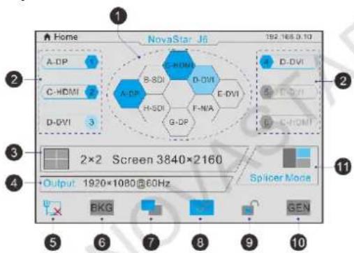
Table 4-1 Home screen descriptions
| No. | Area | Description |
| NovaStar J6192.168.0.10 | Novastar J6: Device name192.168.0.10: Device IP address | |
| 1 | Input source | Display the input source status.Transparent: The input source signal is not accessed.Semi-transparent: The input source signal is accessed, but not in use.Highlighted: The input source signal is accessed and in use. |
| 2 | Layer | Display the layer status and its input source.Transparent: The layer is not opened and the recently used source signal is displayed.Semi-transparent: The layer is opened, but the input source signal is not accessed. The recently used source signal is displayed.Highlighted: The layer is opened and the input source signal is accessed. Thecurrently used source signal is displayed. |
| [64C0] | Screen layout and screen resolution | Display the current screen layout and resolution.In Spicer mode, the supported screen layouts are 1 × 1 , 1 × 2 , 2 × 1 , 1 × 3 , 3 × 1 , 2 × 2 , 1 × 4 and 4 × 1 .In Switcher mode, the supported screen layouts are 1 × 1 , 1 × 2 and 2 × 1 . |
| 4 | Output resolution | The output resolution of a single output connector |
| 5 | Device connection status | Indicate the status of the connection between the control PC or C1 event controller and the device. The device is connected to the control PC via USB port. The device is connected to the control PC via USB port. The device is connected to the control PC or C1 event controller via Ethernet port. The device is connected to the control PC or C1 event controller via Ethernet port. The device is not connected to the control PC or C1 event controller. The device is not connected to the control PC or C1 event controller. |
 | BKG | Indicate the BKG function enabling status.[T7S5]: The BKG function is turned on.[TTKD]: The BKG function is turned off. |
 | Transition effect |  : Fade effect : Fade effect : Cut effect : Cut effect |
| [T058] | Display control | [02X5]: The screen displays the image normally. : The screen fades to black. : The screen fades to black. : The output image is frozen.[245T]: The test pattern is displayed. When the test pattern function is used via the control PC or C1 event controller, this icon will be displayed on the device LCD screen. : The output image is frozen.[245T]: The test pattern is displayed. When the test pattern function is used via the control PC or C1 event controller, this icon will be displayed on the device LCD screen. |
| [8XXY] | Button locking status | Hown the knob and ESC button simultaneously for 5 seconds or longer to lock or unlock all the buttons. : the device is connected to V-Can or C1 event controller, the front panel will be locked automatically and the lock icon will be shown.[G48Y]: The front panel buttons are locked. : the device is connected to V-Can or C1 event controller, the front panel will be locked automatically and the lock icon will be shown.[G48Y]: The front panel buttons are locked. : The front panel buttons are unlocked. : The front panel buttons are unlocked. |
| [C7ZX] | Genlock status | In  : the Genlock status. : the Genlock status. : The Genlock function is turned on and locked.[ATT7H]: The Genlock function is turned on and to be locked.[ZCB2]: The Genlock function is abnormal or the Genlock source is lost.[SZZT]: The Genlock function is turned off. : The Genlock function is turned on and locked.[ATT7H]: The Genlock function is turned on and to be locked.[ZCB2]: The Genlock function is abnormal or the Genlock source is lost.[SZZT]: The Genlock function is turned off. |
| [CWW4] | System mode | In  : the system working mode: Splicer or Switcher : the system working mode: Splicer or Switcher : Switcher mode[S82X]: Splicer mode : Switcher mode[S82X]: Splicer mode |
On the home screen, press the knob to enter the menu screen as shown in Figure 4-2.
Figure 4-2 Main menu
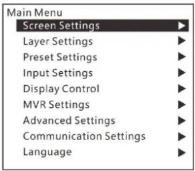
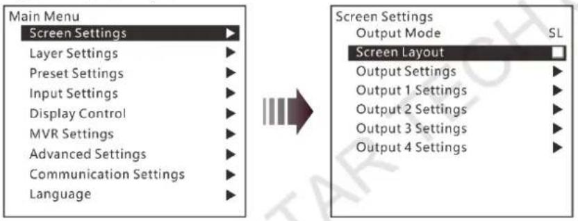
4.3 Screen Settings
On the main menu screen, rotate the knob to select Screen Settings where you can set the output mode, screen layout, output resolution as well as the width and height of the screen area loaded by a certain output connector.
Figure 4-3 Screen layout
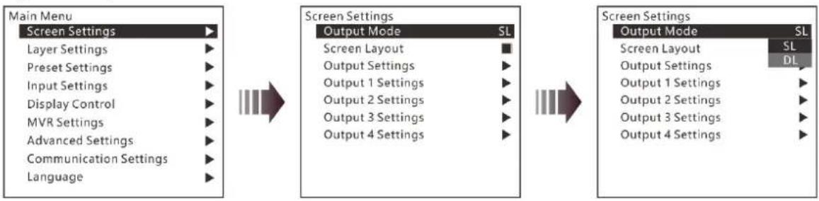
4.3.1 Output Mode
The four groups of DVI connectors can be configured as single link DVI or dual link DVI. When the output mode is different, the connection of the device output connector is different.
- Output Mode: SL
The DVI connector is set to single link mode. The connector connection will vary according to the System Mode.
- When the System Mode is Splicer, four DVI connectors are all used as output connectors.
- When the System Mode is Switcher, DVI 1 and DVI 2 are used as output connectors, while DVI 3 and DVI 4 are unavailable.
- Output Mode: DL
The DVI connector is set to dual link mode. The connector connection will vary according to the System Mode.
- When the System Mode is Splicer, DVI 1 and DVI 3 are used as output connectors, while DVI 2 and DVI 4 are unavailable.
- When the System Mode is Switcher, DVI 1 is used as an output connector, DVI 3 is used for AUX, but DVI 2 and DVI 4 are unavailable.
Figure 4-4 Output mode
flowchart
graph LR
    A["Main Menu"] --> B["Screen Settings"]
    B --> C["Output Mode SL"]
    C --> D["Screen Settings"]
    D --> E["Output Mode SL"]
    E --> F["Screen Settings"]
    F --> G["Output Mode SL"]
    G --> H["Screen Settings"]
    H --> I["Output Mode SL"]
    I --> J["Screen Settings"]
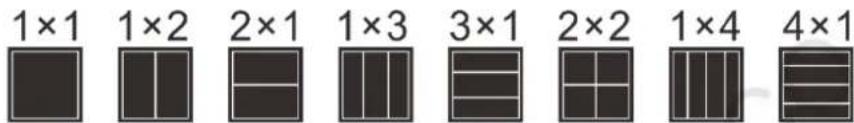
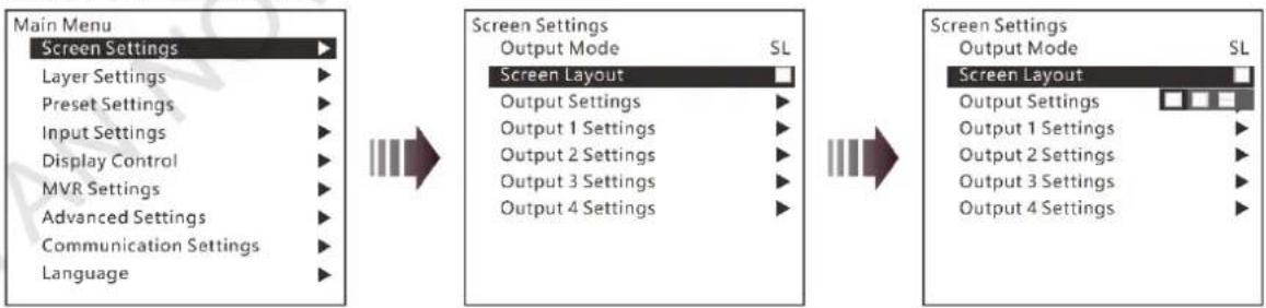
4.3.2 Screen Layout
The screen layout is the screen mosaic mode. The screen layout will vary according to Output Mode and System Mode.
- System mode: Splicer
- When the Output Mode is SL, the following 8 screen layouts are supported.
- When the Output Mode is DL, the following 3 screen layouts are supported.
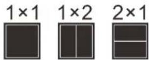
- System mode: Switcher
- When the Output Mode is SL, the following 3 screen layouts are supported.
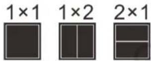
- When the Output Mode is DL, only 1×1 screen layout is supported.
Figure 4-5 Screen layout
flowchart
graph LR
    A["Main Menu"] --> B["Screen Settings"]
    B --> C["Layer Settings"]
    B --> D["Preset Settings"]
    B --> E["Input Settings"]
    B --> F["Display Control"]
    B --> G["MVR Settings"]
    B --> H["Advanced Settings"]
    B --> I["Communication Settings"]
    B --> J["Language"]

    C --> K["Screen Layout"]
    K --> L["Output Mode SL"]
    K --> M["Output Settings ▶"]
    K --> N["Output 1 Settings ▶"]
    K --> O["Output 2 Settings ▶"]
    K --> P["Output 3 Settings ▶"]
    K --> Q["Output 4 Settings ▶"]

    L --> R["Screen Settings"]
    R --> S["Output Mode SL"]
    R --> T["Screen Layout ▶"]
    T --> U["Output Settings □□□□"]
    T --> V["Output 1 Settings ▶"]
    T --> W["Output 2 Settings ▶"]
    T --> X["Output 3 Settings ▶"]
    T --> Y["Output 4 Settings ▶"]
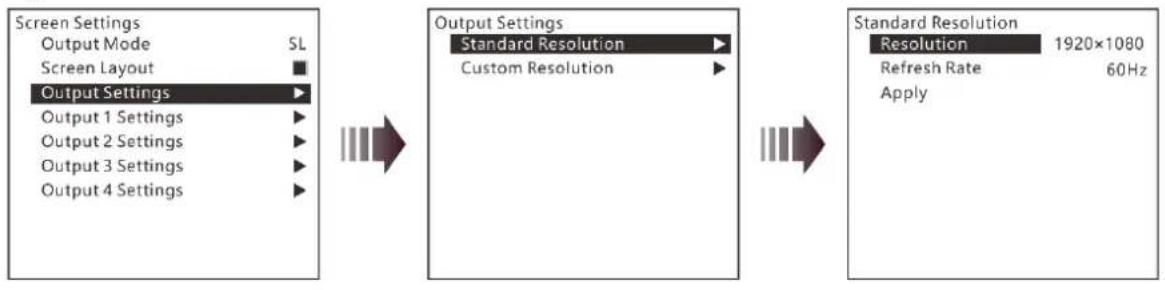
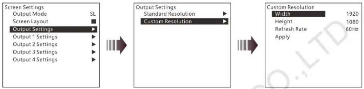
4.3.3 Output Settings
Output settings allow you to set the output resolution of the DVI output connector. Standard resolutions and custom resolutions are both supported.
- Output Mode: SL
Output resolution is 1920×1080 and refresh rate is 60 Hz. Custom width range is 600–3840. Custom height range is 600–3518. Refresh rate range is 24 Hz–120 Hz.
- Output Mode: DL
Output resolution is 1920×1080. Refresh rate is 60 Hz. Custom width range is 1200–7680. Custom height range is 600–3579. Refresh rate range is 24 Hz–120 Hz.
Figure 4-6 Standard resolution
flowchart
graph LR
    A["Screen Settings"] --> B["Output Mode SL"]
    A --> C["Screen Layout ■"]
    A --> D["Output Settings ▶"]
    D --> E["Output 1 Settings ▶"]
    D --> F["Output 2 Settings ▶"]
    D --> G["Output 3 Settings ▶"]
    D --> H["Output 4 Settings ▶"]

    I["Output Settings"] --> J["Standard Resolution ▶"]
    I --> K["Custom Resolution ▶"]

    L["Standard Resolution"] --> M["Resolution 1920×1080"]
    L --> N["Refresh Rate 60Hz"]
    L --> O["Apply"]
Figure 4-7 Custom resolution
flowchart
graph LR
    A["Screen Settings\nOutput Mode SL\nScreen Layout"] --> B["Output Settings\nOutput 1 Settings"]
    A --> C["Output 2 Settings"]
    A --> D["Output 3 Settings"]
    A --> E["Output 4 Settings"]
    B --> F["Output Settings\nStandard Resolution"]
    B --> G["Custom Resolution"]
    F --> H["Custom Resolution\nWidth 1920\nHeight 1080\nRefresh Rate 60Hz\nApply"]
Rotate the knob to select a standard resolution, and press the knob to confirm the selection. Rotate the knob to adjust the custom resolution or use the number buttons on the front panel to enter a custom resolution. After the resolution is set, rotate the knob to select Apply to make the settings take effect.
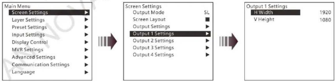
4.3.4 Output Connector Settings
Output 1/2/3/4 settings allow you to set the width and height of the screen area loaded by an output connector.
- When two or more connectors are used together for horizontal mosaic output, the height change for one connector will apply to both or all connectors, but the width for a single connector can be changed.
- When two or more connectors are used together for vertical mosaic output, the width change for one connector will apply to both or all connectors, but the height for a single connector can be changed.
Figure 4-8 Output connector settings
flowchart
graph LR
    A["Main Menu"] --> B["Screen Settings"]
    B --> C["Output Mode SL"]
    B --> D["Screen Layout ■"]
    B --> E["Output Settings ▶"]
    B --> F["Output 1 Settings ▶"]
    B --> G["Output 2 Settings ▶"]
    B --> H["Output 3 Settings ▶"]
    B --> I["Output 4 Settings ▶"]
    J["Main Menu"] --> K["Screen Settings"]
    K --> L["Output Mode SL"]
    K --> M["Screen Layout ■"]
    K --> N["Output Settings ▶"]
    K --> O["Output 1 Settings ▶"]
    K --> P["Output 2 Settings ▶"]
    K --> Q["Output 3 Settings ▶"]
    K --> R["Output 4 Settings ▶"]
    S["Main Menu"] --> T["Screen Settings"]
    T --> U["H Width 1920"]
    T --> V["V Height 1080"]
4.4 Layer Settings
The J6 supports one BKG and six independent layers. You can set the layer layout simply by selecting a layout from Layer Layout or set the parameters for each layer.
On the main menu screen, go to Layer Settings > Layer Layout to enter the layer layout settings screen.
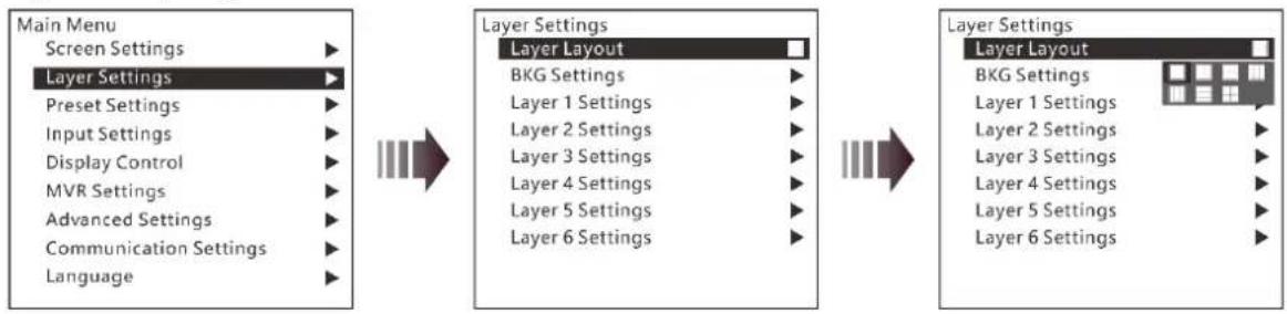
4.4.1 Layer Layout
The J6 provides 7 layer layouts. You can select the desired layout in Layer Layout, and then all the layers will together fill the screen. The layer quantity, size and position will be set automatically according to the selected layout.
Figure 4-9 Layer layout
flowchart
graph LR
    A["Main Menu\nScreen Settings"] --> B["Layer Settings"]
    B --> C["Layer Layout"]
    C --> D["BKG Settings"]
    C --> E["Layer 1 Settings"]
    C --> F["Layer 2 Settings"]
    C --> G["Layer 3 Settings"]
    C --> H["Layer 4 Settings"]
    C --> I["Layer 5 Settings"]
    C --> J["Layer 6 Settings"]
    B --> K["Main Menu\nScreen Settings"]
    B --> L["Layer Settings"]
    L --> M["Layer Layout"]
    M --> N["BKG Settings"]
    M --> O["Layer 1 Settings"]
    M --> P["Layer 2 Settings"]
    M --> Q["Layer 3 Settings"]
    M --> R["Layer 4 Settings"]
    M --> S["Layer 5 Settings"]
    M --> T["Layer 6 Settings"]
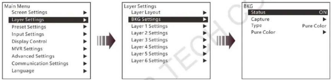
4.4.2 BKG Settings
The J6 supports BKG settings. You can load an image file from the control PC, capture an input source image displayed on the screen or select a pure color as the BKG image. BKG has the lowest priority and fills the whole screen.
On the layer settings screen, rotate the knob to select BKG Settings and press the knob to enter the BKG settings screen. You can turn on or turn off the BKG function.
Figure 4-10 BKG
flowchart
graph LR
    A["Main Menu"] --> B["Layer Settings"]
    B --> C["Layer Layout"]
    C --> D["BKG Settings"]
    D --> E["Layer 1 Settings"]
    D --> F["Layer 2 Settings"]
    D --> G["Layer 3 Settings"]
    D --> H["Layer 4 Settings"]
    D --> I["Layer 5 Settings"]
    D --> J["Layer 6 Settings"]

    B --> K["Screen Settings"]
    B --> L["Preset Settings"]
    B --> M["Input Settings"]
    B --> N["Display Control"]
    B --> O["MVR Settings"]
    B --> P["Advanced Settings"]
    B --> Q["Communication Settings"]
    B --> R["Language"]

    C --> S["Status ON"]
    D --> T["Capture ▶"]
    D --> U["Type Pure Color ▶"]
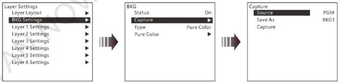
BKG Capture
You can capture the current display image on PGM or the current frame of the select input source, and save the captured image as the BKG image.
Figure 4-11 BKG capture
flowchart
graph LR
    A["Layer Settings"] --> B["BKG Settings"]
    B --> C["Layer Layout"]
    B --> D["Layer 1 Settings"]
    B --> E["Layer 2 Settings"]
    B --> F["Layer 3 Settings"]
    B --> G["Layer 4 Settings"]
    B --> H["Layer 5 Settings"]
    B --> I["Layer 6 Settings"]

    J["BKG Status"] --> K["On Capture"]
    K --> L["Type Pure Color"]
    K --> M["Pure Color"]

    N["Capture Source"] --> O["PGM Save As"]
    N --> P["BKG1 Capture"]
- On the BKG settings screen, go to Capture > Source to select an input source or PGM.
- Rotate the knob to select Save As to save the captured BKG image to a specified location.
- Rotate the knob to select Capture and press the knob, then the system will automatically capture the current frame of the image and save the captured BKG image to the specified location.
Note:
If a BKG image already exists in the selected location, the captured BKG image will overwrite the existing one.
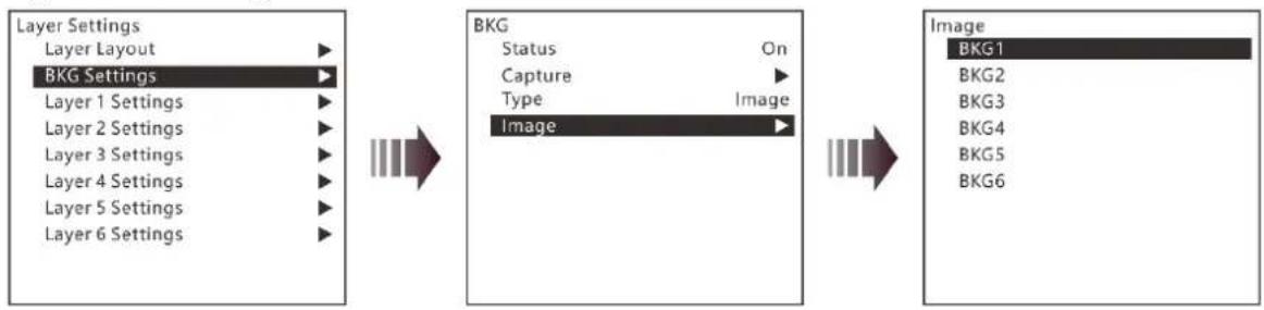
BKG Image
The J6 supports up to 6 BKG images. You can load an image file from the control PC or C1 event controller, or capture an input source image displayed on the screen as the BKG image.
-
On the BKG settings screen, set the BKG type to Image.
-
Rotate the knob to select Image and press the knob to enter the BKG image selection screen.
- Rotate the knob to select a BKG image and press the knob to apply the selected BKG image to PVW.
Figure 4-12 BKG image
flowchart
graph LR
    A["Layer Settings"] --> B["BKG Settings"]
    B --> C["Layer Layout"]
    B --> D["Layer 1 Settings"]
    B --> E["Layer 2 Settings"]
    B --> F["Layer 3 Settings"]
    B --> G["Layer 4 Settings"]
    B --> H["Layer 5 Settings"]
    B --> I["Layer 6 Settings"]

    J["BKG"] --> K["Status On"]
    J --> L["Capture"]
    J --> M["Type Image"]
    J --> N["Image"]

    O["Image"] --> P["BKG1"]
    O --> Q["BKG2"]
    O --> R["BKG3"]
    O --> S["BKG4"]
    O --> T["BKG5"]
    O --> U["BKG6"]
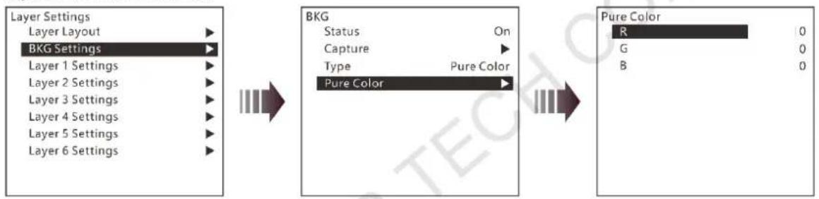
Pure Color BKG
The J6 supports pure color BKG. When the BKG type is Pure Color, you need to set the individual R, G and B value for the pure color BKG.
Figure 4-13 Pure color BKG
flowchart
graph LR
    A["Layer Settings"] --> B["BKG Settings"]
    B --> C["Layer Layout"]
    B --> D["Layer 1 Settings"]
    B --> E["Layer 2 Settings"]
    B --> F["Layer 3 Settings"]
    B --> G["Layer 4 Settings"]
    B --> H["Layer 5 Settings"]
    B --> I["Layer 6 Settings"]

    J["BKG Status On"] --> K["Capture"]
    K --> L["Type Pure Color"]
    L --> M["Pure Color"]

    N["Pure Color R 0"]
    N --> O["G 0"]
    N --> P["B 0"]
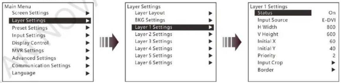
4.4.3 Layer Settings
The J6 supports 6 layers. The input source, size, position, priority and input cropping of each layer can be set. Here take Layer 1 as an example to illustrate.
Figure 4-14 Layer settings
flowchart
graph LR
    A["Main Menu"] --> B["Layer Settings"]
    B --> C["Layer 1 Settings"]
    C --> D["Layer 1 Settings"]
    D --> E["Status On"]
    D --> F["Input Source E-DVI"]
    D --> G["H Width 800"]
    D --> H["V Height 600"]
    D --> I["Initial X 60"]
    D --> J["Initial Y 40"]
    D --> K["Priority 2"]
    D --> L["Input Crop ▶"]
    D --> M["Border ▶"]
● Status: Open or close the layer.
● Input Source: Set the input source for the layer.
● H Width: Adjust the layer width. The default value is 800.
● V Height: Adjust the layer height. The default value is 600.
- Initial X: Adjust the initial horizontal coordinate of the layer. The default value is 0.
- Initial Y: Adjust the initial vertical coordinate of the layer. The default value is 0.
- Priority: Set the displaying order of the layers. The range is 1–6, and 6 indicates the layer is at the top.
- Input Crop: Crop the input source image and make the cropped part display in the whole layer area.

- Layer 1 Input Crop: Turn on or turn off the input crop function for Layer 1.
- H Width: Set the width of the desired part as shown in the above figure.
- V Height: Set the height of the desired part as shown in the above figure.
- Initial X: Set the horizontal initial coordinate of the cropped part upon the current input source with the top left corner as the reference point, which is shown in the above figure.
- Initial Y: Set the vertical initial coordinate of the cropped part upon the current input source with the top left corner as the reference point, which is shown in the above figure.
- Border: Set the layer border type and color.
- Status: Turn on or turn off the layer border.
- Type: Set the layer border type. The options are Inner and Outer.
- Color: Set the layer border color. Nine pure colors are provided. When you want to customize the border color, you can define the color by adjusting the individual R, G and B colors.
- Reset: Reset all the border parameters to defaults.
Note:
When you set the border color to one of the provided pure colors, R, G and B color adjustment is not supported.
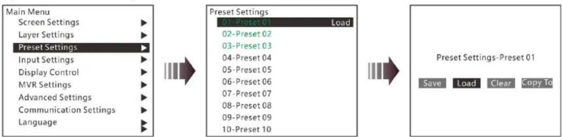
4.5 Preset Settings
The J6 supports up to 32 presets. After the layer settings are complete, you can save the settings as a preset and load the preset. When the preset name is in green, the current preset has data and can be loaded, cleared or copied.
Rotate the knob to select a preset and press the knob to enter the preset settings screen.
- Save: Save the current layer settings to a target preset.
-
Load:
-
When the System Mode is Splicer, you can load the current preset to the screen.
-
When the System Mode is Switcher, you can load the current preset to PVW.
-
Clear: Clear all the data in the selected preset.
- Copy To: Copy a saved preset to a new preset.
Rotate the knob to select a saved preset, and press the knob to enter the preset settings screen. Select Copy To and press the knob to select a target preset location to complete the saving action. After copied successfully, the newly-saved preset turns green.
Figure 4-15 Preset settings
flowchart
graph LR
    A["Main Menu"] --> B["Preset Settings"]
    B --> C["01-Preset 01 Load"]
    B --> D["02-Preset 02"]
    B --> E["03-Preset 03"]
    B --> F["04-Preset 04"]
    B --> G["05-Preset 05"]
    B --> H["06-Preset 06"]
    B --> I["07-Preset 07"]
    B --> J["08-Preset 08"]
    B --> K["09-Preset 09"]
    B --> L["10-Preset 10"]
    M["Save Load Clear Copy To"] --> N["Preset Settings-Preset 01"]
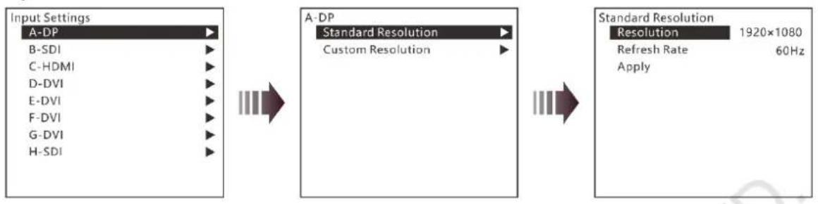
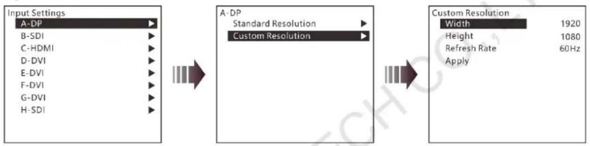
4.6 Input Settings
On the input settings screen, you can set the input resolution. The standard resolution and custom resolution are both supported.
Figure 4-16 Standard resolution
flowchart
graph LR
    A["Input Settings"] --> B["A-DP"]
    B --> C["B-SDI"]
    B --> D["C-HDMI"]
    B --> E["D-DVI"]
    B --> F["E-DVI"]
    B --> G["F-DVI"]
    B --> H["G-DVI"]
    B --> I["H-SDI"]

    A --> J["A-DP"]
    J --> K["Standard Resolution"]
    K --> L["Custom Resolution"]

    J --> M["Standard Resolution"]
    M --> N["Resolution 1920x1080"]
    M --> O["Refresh Rate 60Hz"]
    M --> P["Apply"]
Figure 4-17 Custom resolution
flowchart
graph LR
    A["Input Settings"] --> B["A-DP"]
    B --> C["B-SDI"]
    B --> D["C-HDMI"]
    B --> E["D-DVI"]
    B --> F["E-DVI"]
    B --> G["F-DVI"]
    B --> H["G-DVI"]
    B --> I["H-SDI"]

    J["A-DP\nStandard Resolution"] --> K["Custom Resolution"]

    L["Custom Resolution\nWidth 1920\nHeight 1080\nRefresh Rate 60Hz\nApply"] --> M["Arrow to next step"]
Note:
The SDI connector does not support input resolution settings.
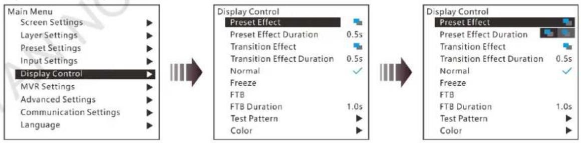
4.7 Display Control
Display control allows you to control the output display style and transition. The submenus vary according to different system modes.
- When the System Mode is Splicer, the menu is shown in Figure 4-18.
Figure 4-18 Display control submenus for Splicer mode
flowchart
graph LR
    A["Main Menu"] --> B["Display Control"]
    B --> C["Display Control"]
    subgraph A
        A1["Screen Settings"] --> A2["Layer Settings"] --> A3["Preset Settings"] --> A4["Input Settings"] --> A5["Display Control"]
        A6["MVR Settings"] --> A7["Advanced Settings"] --> A8["Communication Settings"] --> A9["Language"]
    end
    subgraph B
        B1["Preset Effect"] --> B2["Preset Effect Duration 0.5s"] --> B3["Transition Effect"] --> B4["Transition Effect Duration 0.5s"] --> B5["Normal ✓"]
        B6["Freeze"] --> B7["FTB Duration 1.0s"] --> B8["Test Pattern"] --> B9["Color"]
    end
    subgraph C
        C1["Preset Effect"] --> C2["Preset Effect Duration 0.5s"] --> C3["Transition Effect"] --> C4["Transition Effect Duration 0.5s"] --> C5["Normal ✓"]
        C6["Freeze"] --> C7["FTB Duration 1.0s"] --> C8["Test Pattern"] --> C9["Color"]
    end
- Preset Effect: Set the effect for switching preset. Fade and cut effects are supported.
- Preset Effect Duration: Set the duration for switching preset. The range is 0.50s–2.00s and the default value is 0.50s.
- Transition Effect: Set the effect for layer image switching. Fade and cut effects are supported.
- Transition Effect Duration: Set the duration of the transition effect. The range is 0.50s–2.00s and the default value is 0.50s.
- When the System Mode is Switcher, the menu is shown in Figure 4-19.
Figure 4-19 Display control submenus for Switcher mode
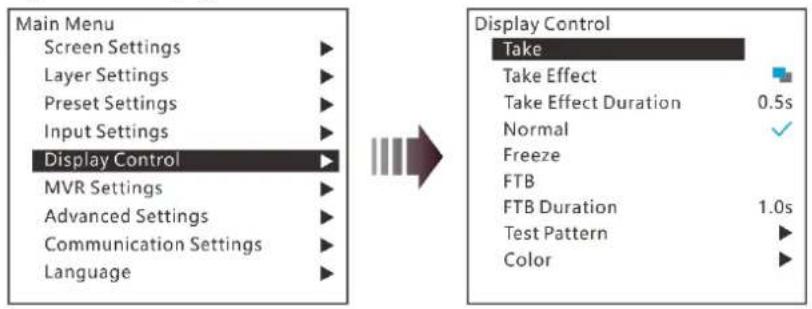
● Take: Send PVW to PGM.
● Take Effect: Set the effect when sending PVW to PGM. Fade and cut effects are supported.
- Take Effect Duration: Set the duration for Take effect. The range is 0.50s–2.00s and the default value is 0.50s.
Normal
Exit the freeze or FTB mode and display the image normally.
Freeze
Freeze the current frame of the output image.
FTB
- FTB: Make the output image fade to black.
- FTB Duration: Set the time length of the whole FTB process. The range is 0.0s–2.0s and the default value is 1.0s.
Color
Adjust the brightness, contrast, saturation and hue of the input, layer and output image.
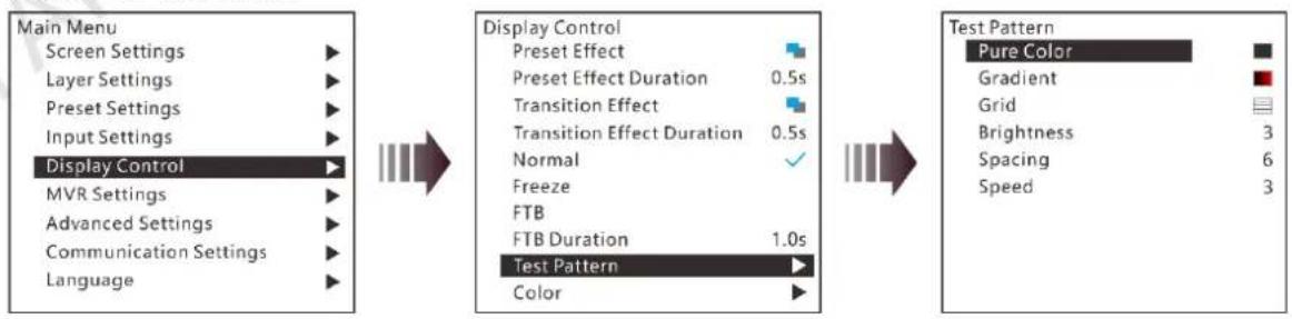
Test Pattern
You can test whether the screen can display the output image color normally by comparing the displayed image with the test pattern. On the main menu screen, go to Display Control > Test Pattern and press the knob to enter the test pattern settings screen.
Figure 4-20 Test pattern
flowchart
graph LR
    A["Main Menu"] --> B["Display Control"]
    B --> C["Test Pattern"]
    C --> D["Test Pattern"]
    style A fill:#f9f,stroke:#333
    style B fill:#ccf,stroke:#333
    style C fill:#cfc,stroke:#333
    style D fill:#fcc,stroke:#333
- Pure Color
Test whether the screen can display the color normally. The J6 provides 8 pure colors. - Gradient
Test whether the screen can display the image normally. The J6 provides 8 gradients.
Grid
Test whether there are uncontrollable pixels on the screen. The J6 provides 6 grids.
- Brightness
Set the brightness of the test pattern. The range is 1–4 and the default value is 3.
- Spacing
When the test pattern is Gradient or Grid, you can set the spacing. The range is 1–8 and the default value is 5.
- Speed
When the test pattern is Grid, you can set the moving speed. The range is 1–4 and the default value is 3.
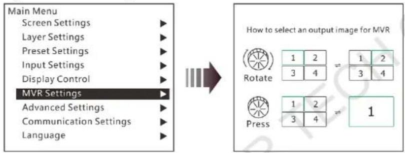
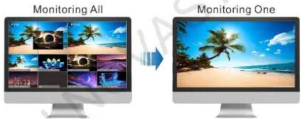
4.8 MVR Settings
You can set to monitor a single input source, PVW or PGM. All the input sources, PVW and PGM are monitored by default.
Step 1 On the main menu screen, rotate the knob to select MVR Settings.
Step 2 Press the knob to enter the MVR settings screen where you can learn how to select an output image for MVR.
Figure 4-21 MVR settings
flowchart
graph LR
    A["Main Menu"] --> B["Screen Settings"]
    A --> C["Layer Settings"]
    A --> D["Preset Settings"]
    A --> E["Input Settings"]
    A --> F["Display Control"]
    A --> G["MVR Settings"]
    A --> H["Advanced Settings"]
    A --> I["Communication Settings"]
    A --> J["Language"]

    K["How to select an output image for MVR"] --> L["Rotate: 1 2 = 1 2\n3 4 = 3 4"]
    K --> M["Press: 1 2 = 1\n3 4 = 1"]
Step 3 Rotate the knob to select to a single input source, PVW or PGM and press the knob to display the selected one in full screen.
Step 4 Press the knob again to exit the full screen display and go back to monitor all the input sources, PVW and PGM.
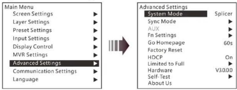
4.9 Advanced Settings
On the main menu screen, rotate the knob to select Advanced Settings and press the knob to enter the advanced settings screen. You can set the system mode, sync mode, Fn button function, go homepage time, factory reset and HDCP function, as well as view the hardware version and company-related information.
Figure 4-22 Advanced settings
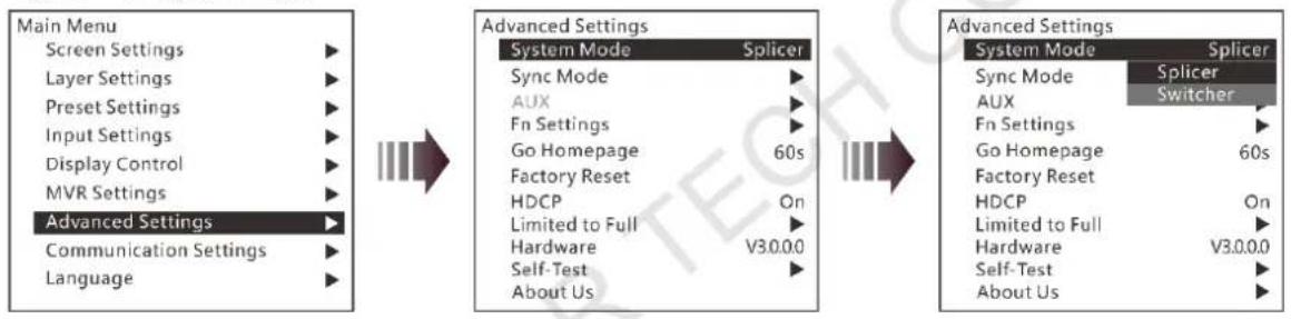
4.9.1 System Mode
The J6 supports two system modes: Splicer and Switcher. When a different system mode is selected, the device loading capacity and operations are also different.
- Splicer: All the operations to the layers will be displayed on the LED screen simultaneously.
- Switcher: All the operations to the layers will be firstly displayed on the PVW, and then sent to the LED screen from the PVW by using the TAKE button after you have completed the editing.
Figure 4-23 System mode
flowchart
graph LR
    A["Main Menu"] --> B["Advanced Settings"]
    B --> C["Advanced Settings"]

    subgraph Main Menu
        A1["Screen Settings"]
        A2["Layer Settings"]
        A3["Preset Settings"]
        A4["Input Settings"]
        A5["Display Control"]
        A6["MVR Settings"]
        A7["Advanced Settings"]
        A8["Communication Settings"]
        A9["Language"]
    end

    subgraph Advanced Settings
        B1["System Mode Splicer"]
        B2["Sync Mode"]
        B3["AUX"]
        B4["Fn Settings"]
        B5["Go Homepage 60s"]
        B6["Factory Reset"]
        B7["HDCP On"]
        B8["Limited to Full"]
        B9["Hardware V3.0.0.0"]
        B10["Self-Test"]
        B11["About Us"]
    end

    subgraph Advanced Settings
        C1["System Mode Splicer"]
        C2["Sync Mode Splicer"]
        C3["AUX Switcher"]
        C4["Fn Settings"]
        C5["Go Homepage 60s"]
        C6["Factory Reset"]
        C7["HDCP On"]
        C8["Limited to Full"]
        C9["Hardware V3.0.0.0"]
        C10["Self-Test"]
        C11["About Us"]
    end
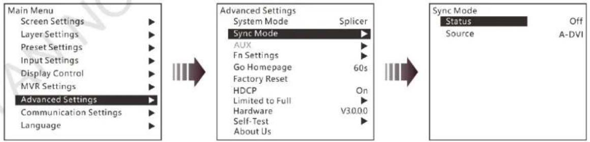
4.9.2 Sync Mode
- Status: Turn on or turn off the sync mode. The function is turned off by default.
- Source: Rotate the knob to select an input source as the target sync source.
Figure 4-24 Sync mode
flowchart
graph LR
    A["Main Menu"] --> B["Advanced Settings"]
    B --> C["Sync Mode"]
    C --> D["Sync Mode Status Off Source A-DVI"]
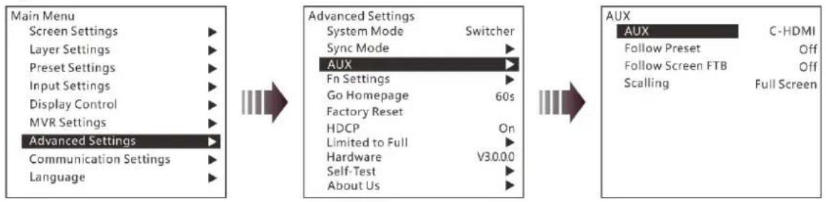
4.9.3 AUX
When the system mode is Switcher, the J6 supports AUX settings, allowing you to set one input source as the AUX input source.
Figure 4-25 AUX
flowchart
graph LR
    A["Main Menu"] --> B["Advanced Settings"]
    B --> C["AUX"]
    C --> D["AUX"]
    D --> E["C-HDMI"]
    style A fill:#f9f,stroke:#333
    style B fill:#ccf,stroke:#333
    style C fill:#cfc,stroke:#333
    style D fill:#fcc,stroke:#333
● AUX: Select the AUX input source.
- Follow Preset: Set whether the AUX data follow the preset switching.
- On: If the preset has AUX data, the AUX will be switched automatically during preset switching.
- Off: The AUX will not be switched during preset switching.
- Follow Screen FTB: Set whether the AUX output follows the main screen to perform FTB.
- On: Turn on the function and the AUX will follow the screen FTB.
- Off: Turn off the function and the AUX will not follow the screen FTB and will output normally
- Scaling: Set the AUX output display.
- Full Screen: Display the image in full screen of the AUX display.
- Proportional: Scale the image proportionally and then display it on the screen.
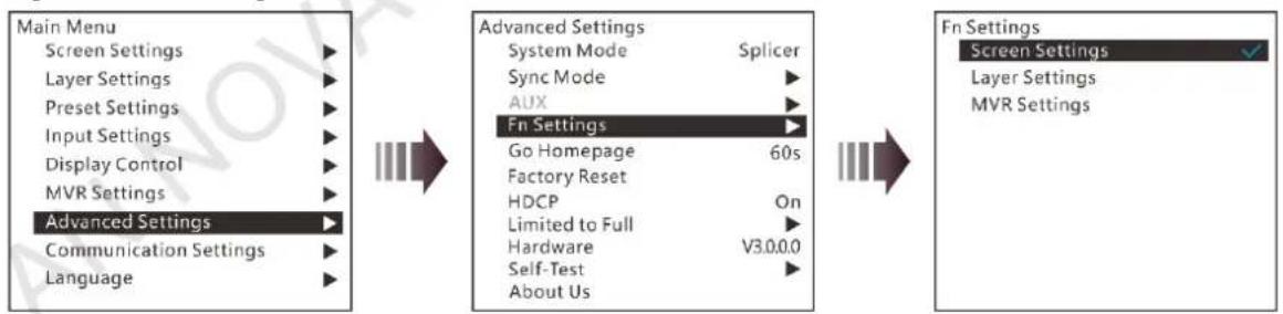
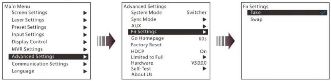
4.9.4 Fn Settings
When a different system mode is selected, the Fn button function may vary. In Splicer mode, after you have completed the Fn settings, press the Fn button to enter the settings screen of the function that you have set for the button. In Switcher mode, after you have completed the Fn settings, press the Fn button to send PVW to PGM.
- In splicer mode, the Fn button can be set as the shortcut button for Screen Settings, Layer Settings or MVR Settings.
Figure 4-26 Fn settings
flowchart
graph LR
    A["Main Menu"] --> B["Advanced Settings"]
    B --> C["Fn Settings"]
    A --> D["Screen Settings"]
    A --> E["Layer Settings"]
    A --> F["Preset Settings"]
    A --> G["Input Settings"]
    A --> H["Display Control"]
    A --> I["MVR Settings"]
    A --> J["Advanced Settings"]
    J --> K["Communication Settings"]
    J --> L["Language"]

    B --> M["System Mode"]
    M --> N["Splicer"]
    M --> O["Sync Mode"]
    O --> P["AUX"]
    P --> Q["Fn Settings"]
    Q --> R["Go Homepage 60s"]
    Q --> S["Factory Reset"]
    Q --> T["HDCP On"]
    Q --> U["Limited to Full"]
    Q --> V["Hardware V3.0.0.0"]
    Q --> W["Self-Test"]
    Q --> X["About Us"]

    C --> Y["Screen Settings"]
    C --> Z["Layer Settings"]
    C --> AA["MVR Settings"]
- In switcher mode, the Fn button can be set as the shortcut button for switching between PVW and PGM. Take and Swap modes are supported.
- Take: Press the Fn button to send PVW to PGM. The images on PVW and PGM are the same.
- Swap: Press the Fn button to swap the images displayed on PVW and PGM.
Figure 4-27 Fn settings
flowchart
graph LR
    A["Main Menu"] --> B["Advanced Settings"]
    B --> C["Fn Settings"]
    C --> D["Take"]
    C --> E["Swap"]

    subgraph Section1
        F["Screen Settings"] --> G["Layer Settings"] --> H["Preset Settings"] --> I["Input Settings"] --> J["Display Control"] --> K["MVR Settings"] --> L["Advanced Settings"]
        M["Communication Settings"] --> N["Language"] --> O["Advanced Settings"]
    end

    subgraph Section2
        P["System Mode"] --> Q["Switcher"] --> R["Sync Mode"] --> S["AUX"] --> T["Fn Settings"]
        U["Go Homepage"] --> V["60s"] --> W["Factory Reset"]
        X["HDCP"] --> Y["On"] --> Z["Limited to Full"] --> AA["Hardware"] --> AB["V3.0.0.0"]
        AC["Self-Test"] --> AD["About Us"] --> AE["Advanced Settings"]
    end
4.9.5 Go Homepage
You can set the time during which the system stays at the current page before returning to the homepage automatically when there is no operation performed.
- Range: 30s–3600s
- Default value: 60s
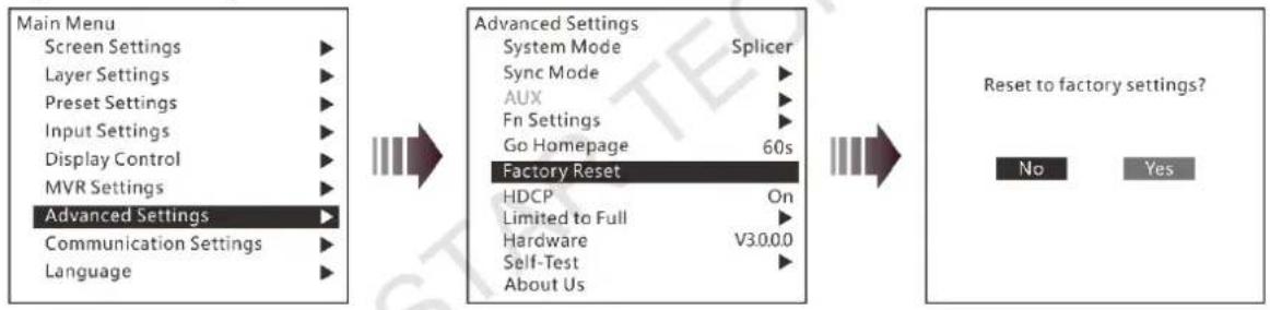
4.9.6 Factory Reset
When you need to clear all the user data in the device, you can select Factory Reset to reset the device to factory defaults.
Figure 4-28 Factory reset
flowchart
graph LR
    A["Main Menu"] --> B["Advanced Settings"]
    B --> C["Factory Reset"]
    C --> D["Reset to factory settings?"]

    subgraph Before
        E["Screen Settings"] --> F["Layer Settings"] --> G["Preset Settings"] --> H["Input Settings"] --> I["Display Control"] --> J["MVR Settings"] --> K["Communication Settings"] --> L["Language"]
    end

    subgraph After
        M["System Mode"] --> N["Splicer"] --> O["Factory Reset"]
        P["Sync Mode"] --> Q["AUX"] --> R["Go Homepage 60s"]
        S["Fn Settings"] --> T["Go Homepage 60s"]
        U["HDCP"] --> V["On"] --> W["V3.0.0"]
        X["Limited to Full"] --> Y["Hardware"] --> Z["Self-Test"] --> AA["About Us"]
    end

    subgraph Final
        AB["No"] --> AC["Yes"]
    end
4.9.7 HDCP
The HDCP function is available for HDMI and DVI input connectors.
- On: Enable the HDCP function.
- Off: Disable the HDCP function.
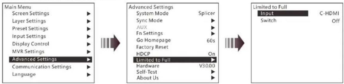
4.9.8 RGB Color Range Converting
This function can automatically convert the limited RGB color range to full RGB range for the input source, so the device can process the source precisely.
Figure 4-29 RGB color range settings
flowchart
graph LR
    A["Main Menu"] --> B["Screen Settings"]
    A --> C["Layer Settings"]
    A --> D["Preset Settings"]
    A --> E["Input Settings"]
    A --> F["Display Control"]
    A --> G["MVR Settings"]
    A --> H["Advanced Settings"]
    A --> I["Communication Settings"]
    A --> J["Language"]

    B --> K["Advanced Settings"]
    K --> L["System Mode Splicer"]
    K --> M["Sync Mode"]
    K --> N["AUX"]
    K --> O["Fn Settings"]
    K --> P["Go Homepage 60s"]
    K --> Q["Factory Reset"]
    K --> R["HDCP On"]
    K --> S["Limited to Full"]
    S --> T["Hardware V30.00"]
    S --> U["Self-Test"]
    S --> V["About Us"]

    L --> W["Limited to Full"]
    W --> X["Input C-HDMI"]
    W --> Y["Switch Off"]
Step 1 Select an input source to be converted.
Step 2 Turn on the function.
- Off: Turn off the limited to full converting function.
- On: Turn on the function. It is recommended you turn on the function when the input source has a limited RGB color range.
4.9.9 Hardware Version
You can view the current device version.
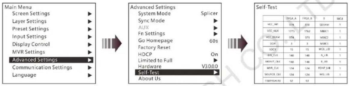
4.9.10 Self-Test
The J6 supports the diagnostics function to check the working status of the device. You can send the test result to the technical staff of NovaStar to help resolve the problem quickly.
Figure 4-30 Self-Test
flowchart
graph LR
    A["Main Menu"] --> B["Advanced Settings"]
    B --> C["System Mode Splicer"]
    B --> D["Sync Mode AUX"]
    B --> E["Fn Settings Go Homepage Factory Reset HDCP On Limited to Full Hardware V3.0.0.0 Self-Test About Us"]
    C --> F["Self-Test"]
    D --> F
    E --> F
    F --> G["TPGA_A FPGA_B 0 MCU"]
    G --> H["VCC_INT 974 870 SDRAM 1"]
    G --> I["VCC_AUX 1775 1762 MMCI 1"]
    G --> J["VCC_BRAM 974 971 MMCI 1"]
    G --> K["DOF 3 3 MMCI 1"]
    G --> L["LOCK 15 15 MCU_LIB 1"]
    G --> M["DIS_CLK 148 148 A_LIB 1"]
    G --> N["KONUT_CLK 148 148 B_LIB 1"]
    G --> O["MVR_CLK 124 124 POINT_LIB 1"]
    G --> P["SOURCE_CLK 124 124 IMG_LIB 1"]
    G --> Q["TEMPREAVE 62 63"]
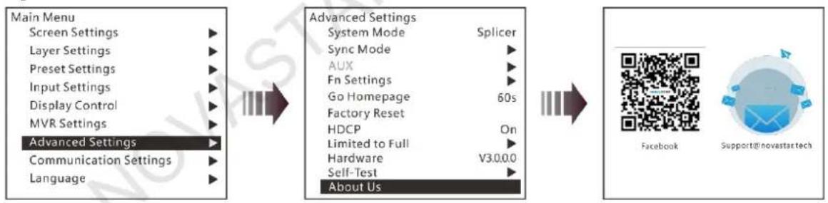
4.9.11 About Us
You can view the Facebook and email address of NovaStar.
Figure 4-31 About us
flowchart
graph LR
    A["Main Menu"] --> B["Advanced Settings"]
    B --> C["System Mode Splicer"]
    B --> D["Sync Mode"]
    B --> E["AUX"]
    B --> F["Fn Settings"]
    B --> G["Go Homepage 60s"]
    B --> H["Factory Reset"]
    B --> I["HDCP On"]
    B --> J["Limited to Full"]
    B --> K["Hardware V3.0.0.0"]
    B --> L["Self-Test"]
    B --> M["About Us"]
    N["Main Menu Screen Settings"] --> B
    O["Main Menu Layer Settings"] --> B
    P["Main Menu Preset Settings"] --> B
    Q["Main Menu Input Settings"] --> B
    R["Main Menu Display Control"] --> B
    S["Main Menu MVR Settings"] --> B
    T["Main Menu Advanced Settings"] --> B
    U["Main Menu Communication Settings"] --> B
    V["Main Menu Language"] --> B
    W["Advanced Settings"] --> X["System Mode Splicer"]
    X --> Y["Sync Mode"]
    Y --> Z["AUX"]
    Z --> AA["Fn Settings"]
    AA --> AB["Go Homepage 60s"]
    AB --> AC["Factory Reset"]
    AC --> AD["HDCP On"]
    AD --> AE["Limited to Full"]
    AE --> AF["Hardware V3.0.0.0"]
    AF --> AG["Self-Test"]
    AG --> AH["About Us"]
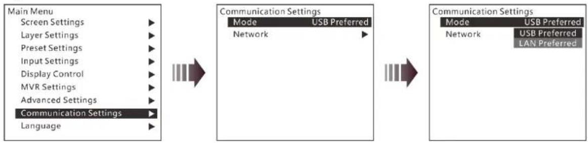
4.10 Communication Settings
On the main menu screen, rotate the knob to select Communication Settings and press the knob to enter the communication settings screen.
Communication Mode
When the device is connected to the control PC via both USB and LAN cables, you can select LAN Preferred (default) or USB Preferred. When LAN Preferred is selected, the J6 is controlled by the control PC via the LAN cable. When USB Preferred is selected, the J6 is controlled by the control PC via the USB cable.
Figure 4-32 Communication mode
flowchart
graph LR
    A["Main Menu"] --> B["Communication Settings"]
    B --> C["Network"]
    C --> D["Communication Settings"]
    D --> E["Network"]
    style A fill:#f9f,stroke:#333
    style B fill:#ccf,stroke:#333
    style C fill:#cfc,stroke:#333
    style D fill:#fcc,stroke:#333
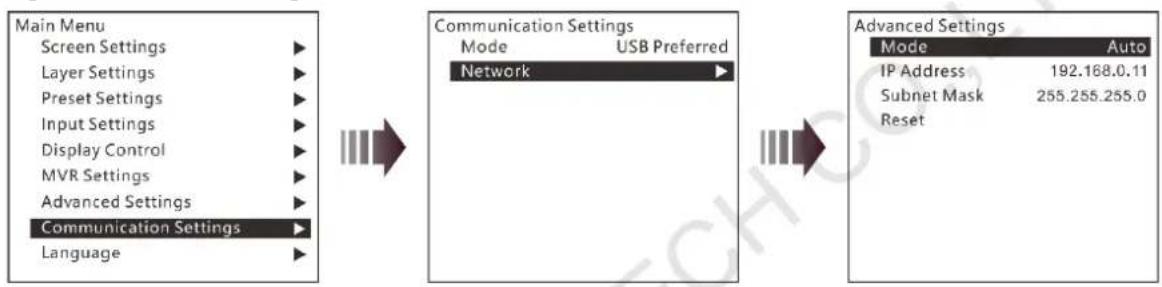
Network Settings
When the device is connected to the control PC via a router, you need to set the IP Address and Subnet Mask to enable communication between the device and control PC.
Figure 4-33 Network settings
flowchart
graph LR
    A["Main Menu"] --> B["Screen Settings"]
    A --> C["Layer Settings"]
    A --> D["Preset Settings"]
    A --> E["Input Settings"]
    A --> F["Display Control"]
    A --> G["MVR Settings"]
    A --> H["Advanced Settings"]
    A --> I["Language"]

    B --> J["Communication Settings"]
    C --> J
    D --> J
    E --> J
    F --> J
    G --> J
    H --> J

    J --> K["Mode"]
    J --> L["USB Preferred"]
    J --> M["Network"]

    N["Advanced Settings"] --> O["Mode"]
    N --> P["Auto"]
    O --> Q["IP Address 192.168.0.11"]
    P --> R["Subnet Mask 255.255.255.0"]
    R --> S["Reset"]
When Mode is set to Auto, the IP Address and Subnet Mask cannot be set, but will be assigned by the router. When Mode is set to Manual, you can set the IP Address and Subnet Mask. Please note that the device IP address cannot be the same as the IP addresses of other devices to avoid network conflict.
You can select Reset to reset the IP Address and Subnet Mask to the defaults.
4.11 Language
You can switch the device UI language. Currently English and Simplified Chinese are supported.
5 V-Can Control
V-Can is a smart control platform for video processors and all-in-one controllers. Thanks to its intuitive UI design and simplified operations, V-Can allows you to easily control and manage all the connected devices.
Step 1 Perform the device connections described in 3 Applications, then V-Can will automatically connect to the J6.
Note:
When multiple J6 units are connected to V-Can, the control PC where V-Can is installed must be on the same LAN with the J6 units. V-Can will automatically search all the J6 units on this LAN and connect all of them.
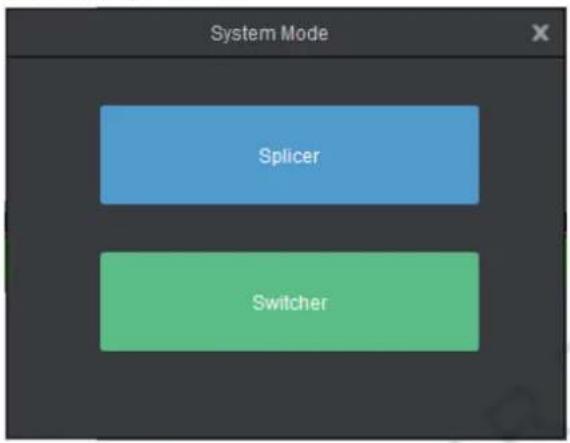
Step 2 Go to Settings > System Mode to pop up the System Mode dialog box, then select the desired system mode.
Figure 5-1 System mode
Step 3 Set the J6 output connector mosaic layout according to the actual screen.
- Click Settings to enter the settings screen.
- Click Mosaic Layout to select the desired layout.
- Click Output to enter the output settings screen.
- Under the Output tab, set the output connector resolution and screen size according to the screen resolution.
Step 4 Set the input resolution and color.
- Click Settings to enter the settings screen.
- Click Input to enter the input settings screen.
- Under the Input tab, click the drop-down arrow next to Source to select an input source, and then select Standard or Custom to set the input resolution.
- Under the Color tab, set the input color.
Step 5 Add layers.
- In Splicer mode, click and drag a signal source to the PGM and then release it to add an 800×600 layer. Drag the layer to change its position, and drag the layer edge or corner to change its size.
- In Switcher mode, click and drag a signal source to the PVW area and then release it to add an 800×600 layer. Drag the layer to change its position, and drag the layer edge or corner to change its size.
Step 6 In Switcher mode, click TAKE or CUT, or push T-Bar to send PVW to PGM.
Note:
V-Can allows you to set the layer layout, size, color and crop the layer. For details, please refer to V-Can User Manual.
6 C1 Control
The C1 event controller is a hardware console of NovaStar specifically designed for video processing products. The C1 adopts a dual LCD screen design. The left one performs the input and output monitoring for the J6. The right one, together with the front panel buttons, allows you to perform operations and control of the J6.
When you need to control the J6 via the C1 event controller, you must switch the system mode to Switcher.
Step 1 Perform the device connections for Switcher mode described in 3 Applications.
Note:
When multiple J6 units are connected to the C1, the C1 must be on the same LAN as the J6 units.
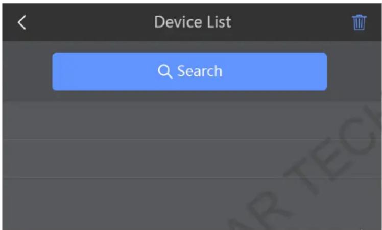
Step 2 On the home screen, click Configuration to enter the configuration page, and then click Search.
Figure 6-1 Searching for devices
Step 3 On the right touch screen, select the devices to be added and then click Add.
Figure 6-2 Adding devices
| Cancel | Add List | Add | ||
| ○ | 1 | J6 | 192.168.0.106 | |
| ○ | 2 | J6 | 192.168.0.107 | |
| ○ | 3 | J6 | 192.168.0.108 | |
| ○ | 4 | J6 | 192.168.0.109 | |
| ○ | 5 | J6 | 192.168.0.110 | |
After the devices are added, you can view the information of those added devices on the Device List page, as shown in the figure below.
Figure 6-3 Device list
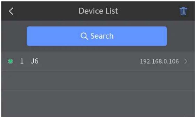
Step 4 Tap next to the device IP address to enter the device properties screen.
Figure 6-4 Device properties
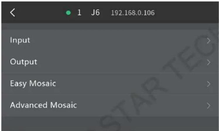
- Input: Set the input resolution and input color.
● Output: Set the output resolution and output color. - Easy Mosaic: By entering the screen width and height, the system will come up with a mosaic plan automatically. You can also press the EASY MOSAIC button in the FUNCTION area on the front panel to enter this screen.
- Advanced Mosaic: This mosaic mode allows you to select a proper mosaic mode and set the mosaic screen size according to the current screen size. You can also press the MOSAIC button in the FUNCTION area on the front panel to enter this screen.
Step 5 Add layers.
- Tap Programming to enter the programming screen.
- Press the ADD LAYER button in the LAYER area on the front panel to add an 800×600 layer to the PVW.
- Press an input source button in the SOURCE area on the front panel to add the input source for the added layer.
Step 6 Select a layer by pressing a layer button in the LAYER area on the front panel. You can adjust the layer position, size and priority by using the joystick.
Step 7 Press the TAKE or CUT button, or push T-Bar to send PVW to PGM.
Note:
For details, please refer to C1 User Manual.
7 Troubleshooting
| Problem | Solution |
| LED screen is not lit | Make sure the power is properly connected and switched on, and the LED screen is connected properly and works normally. |
| DVI has no output image | Make sure the input channel has an input image and the image is displayed correctly.Make sure the layer is opened and accessed with a signal source, and the image is displayed correctly.Check whether the layer is placed outside the LED screen.Make sure the output settings are correct and whether the layer is removed from the LED screen.Make sure the DVI output is properly connected.If a monitor is connected, make sure the monitor supports the output resolution of the video processor.Reset the video processor and try again to check whether there is an image output. |
| DVI output image is abnormal | Check the output settings and make sure whether the parameters are properly set.Check the status bar of the home screen on the LCD panel and make sure other enabled functions do not affect output parameters.Check the connection between the DVI connector and DVI cable.Make sure whether the current connector supports the current input resolution. |
| Images are not displayed normally | Check the input channels of each screen to make sure these channels have input signals and the signals are displayed normally.Make sure the parameters of each screen are set correctly. |
| Fade effect is abnormal | Make sure the channel to be switched has an input signal.Make sure the input source before switching and the source after switching belong to the same signal group. |
| Display is abnormal | Make sure the video processor is properly connected.Make sure the parameter settings of the video processor are correct.Make sure the input signal source is normal. |
8 Specifications
| Connector performance | Common resolutions | |
| DVIHDMI 1.3 | 800×600@50/60/75/85Hz1024×768@48/50/60/75/85Hz1152×864@75Hz1280×720@48/50/60Hz1280×768@48/50/60/75Hz1280×800@50/60Hz1280×960@50/60/85Hz1280×1024@48/50/60/75/85Hz1360×768@60Hz1364×1024@48/50/85Hz | 1366×768@50/60Hz1366×800@50/60Hz1400×1050@48/50/60/75Hz1440×900@60/75/85Hz1600×900@48/50/60Hz1600×1200@48/50/60Hz1680×1050@60Hz1792×1280@60Hz1920×1080@30/48/50/60Hz1920×1200@50/60Hz |
| DP 1.1HDMI 1.4 | 800×600@50/60/75/85Hz1024×768@48/50/60/75/85Hz1152×864@75Hz1280×720@48/50/60Hz1280×768@48/50/60/75Hz1288×800@50/60Hz1280×960@50/60/85Hz1280×1024@48/50/60/75/85Hz1360×768@60Hz1364×1024@48/50/85Hz1400×1050@48/50/60/75Hz1440×900@60/75/85Hz1600×900@48/50/60Hz1600×1200@48/50/60Hz | 1680×1050@60Hz1792×1280@60Hz1920×1080@30/48/50/60Hz1920×1200@50/60Hz2048×1080@30/48/50/60Hz2048×1152@30Hz2304×1152@60Hz2048×1152@60Hz2560×1080@50/60Hz2560×1400@50/60Hz2560×1600@50/60Hz3840×1080@30/50/60Hz3840×2160@30Hz |
| 3G-SDI | 720×486i@59.94Hz720×576i@50Hz1280×720@23.98/24/25/29.97/30/50/59.94/60Hz1920×1080i@50/59.94/60Hz1920×1080@23.98/24/25/29.97/30/50/59.94/60Hz | |
| Physical Specifications | ||
| Electrical specifications | Power connector | 100-240V~, 50/60Hz, 2.1A |
| Power consumption | 50 W | |
| Operating environment | Operating temperature | -20°C to +70°C |
| Operating humidity | 20% to 90%, non-condensing | |
| Storage humidity | 10% to 95%, non-condensing | |
| Physical specifications | Dimensions | 482.6mm × 379.5mm × 95.5mm |
| Net weight | 5.3 kg | |
| Gross weight | 15 kg | |
| Packing information | Accessory | 1x Power cord, 1x Ethernet cable, 2x DVI cables, 1x USB cable, 1x HDMI cable, 1x HDMI to DVI cable, 1x mini DP to DP cable1x Flight case, 1x User Manual |
| Flight case | 593mm × 544mm × 177mm | |
| Certifications | RCM, UL/CUL, IC, CB, RoHS, FCC, LVD, EMC | |
| Noise level (typical at 25° C/77° F) | 50 dB(A) | |
Copyright © 2020 Xi'an NovaStar Tech Co., Ltd. All Rights Reserved.
No part of this document may be copied, reproduced, extracted or transmitted in any form or by any means without the prior written consent of Xi'an NovaStar Tech Co., Ltd.
Trademark
NOVA STAR is a trademark of Xi'an NovaStar Tech Co., Ltd.
Statement
Thank you for choosing NovaStar's product. This document is intended to help you understand and use the product. For accuracy and reliability, NovaStar may make improvements and/or changes to this document at any time and without notice. If you experience any problems in use or have any suggestions, please contact us via the contact information given in this document. We will do our best to solve any issues, as well as evaluate and implement any suggestions.
- Overview
- Introduction
- Features
- Appearance
- Front Panel
- Rear Panel
- Notes:
- Dimensions
- Applications
- Note:
- Menu Operations
- Operation Instructions
- Knob
- ESC
- Button Lock and Unlock
- Home Screen
- Screen Settings
- Output Mode
- Screen Layout
- Output Settings
- Output Connector Settings
- Layer Settings
- Layer Layout
- BKG Settings
- BKG Capture
- BKG Image
- Pure Color BKG
- Layer Settings
- Preset Settings
- Input Settings
- Display Control
- Normal
- Freeze
- FTB
- Color
- Test Pattern
- MVR Settings
- Advanced Settings
- System Mode
- Sync Mode
- AUX
- Fn Settings
- Go Homepage
- Factory Reset
- HDCP
- RGB Color Range Converting
- Step 2 Turn on the function.
- Hardware Version
- Self-Test
- About Us
- Communication Settings
- Communication Mode
- Network Settings
- Language
- V-Can Control
- C1 Control
- Step 5 Add layers.
- Specifications
- Trademark
- Statement
Brand : NovaStar
Model : J6
Category : Processor