
S1201 - Server MSI - Free user manual and instructions
Find the device manual for free S1201 MSI in PDF.

| Product Type | Rackmount Server |
| Model | MSI S1201 |
| Form Factor | 1U |
| Dimensions (W x D x H) | 17.2 x 20.0 x 1.7 inches |
| Weight | Approximately 18 lbs |
| Power Supply | 550W Redundant (1+1) |
| Processor Support | 1x Intel Xeon E5-2600 v4 series |
| Memory Slots | 16x DDR4 ECC Registered DIMM |
| Storage Bays | 4x 3.5" SATA/SAS hot-swap |
| Expansion Slots | 2x PCIe 3.0 x16 |
| Network Interfaces | 2x Gigabit Ethernet, 1x IPMI |
| Management | IPMI 2.0, KVM over IP |
| Operating Temperature | 10°C to 35°C |
| Humidity Range | 8% to 90% non-condensing |
| Power Consumption (max) | 450W |
| Maintenance | Clean air filter monthly; vacuum dust from chassis |
| Safety Features | Overheat protection, redundant PSU, chassis intrusion detection |
| Repairability | Hot-swappable drives and fans; tool-less access to memory |
Frequently Asked Questions - S1201 MSI
User questions about S1201 MSI
0 question about this device. Answer the ones you know or ask your own.
Ask a new question about this device
Download the instructions for your Server in PDF format for free! Find your manual S1201 - MSI and take your electronic device back in hand. On this page are published all the documents necessary for the use of your device. S1201 by MSI.
USER MANUAL S1201 MSI
Regulatory Notices 4
Safety Information 6
System Specifications 7
System Overview 8
System LED Indicators 11
Motherboard Overview 12
Motherboard Connectors 13
Power Connectors 13
Storage Connectors 15
FPC Connectors....18
Fan Connectors 20
Other Connectors and Headers 21
Motherboard Expansion Slots 26
Motherboard Jumpers 27
Onboard LEDs. 28
Memory 34
Mixing of DIMM Types within a Channel. 35
Recommended Memory Population 36
Installing Memory Modules 38
M.2 M Key 39
Installing M.2 SSD 39
PCIe Add-in Card 40
Installing PCIe Add-in Card ____ 40
Installing Riser Card Assembly 41
System Fan 42
Installing 1U Fan 42
Power Supply Unit (PSU) 43
Installing PSU 43
Cable Routing 44
8-pin to 8-pin Power Cable ____ ____ ____ ____ ____ ____ ____ ____ ____ ____ ____ ____ ____ ____ ____ ____ ____
12C Cable 44
Slimline SAS 4i to Slimline SAS 4i Cable (for SATA) ____ ____ ____ ____ 45
Slimline SAS 4i to SlimlineSAS 8i Cable (for NVMe) 45
Slimline SAS 8i to Slimline SAS 8i Cable. 46
Regulatory Notices
WEEE Statement
Under the European Union ("EU") Directive on Waste Electrical and Electronic Equipment, Directive 2012/19/EU, products of "electrical and electronic equipment" cannot be discarded as municipal waste anymore and manufacturers of covered electronic equipment will be obligated to take back such products at the end of their useful life.
Chemical Substances Information
In compliance with chemical substances regulations, such as the EU REACH Regulation (Regulation EC No. 1907/2006 of the European Parliament and the Council), MSI provides the information of chemical substances in products at:
https://csr.msi.com/global/index
CE Conformity
Hereby, Micro-Star International CO., LTD declares that this device is in compliance with the essential safety requirements and other relevant provisions set out in the European Directive.
FCC-A Radio Frequency Interference Statement
This equipment has been tested and found to comply with the limits for a Class A digital device, pursuant to Part 15 of the FCC Rules. These limits are designed to provide reasonable protection against harmful interference when the equipment is operated in a commercial environment. This equipment generates, uses and can radiate radio frequency energy and, if not installed and used in accordance with the instruction manual, may cause harmful interference to radio communications. Operation of this equipment in a residential area is likely to cause harmful interference, in which case the user will be required to correct the interference at his own expense.
Notice 1
The changes or modifications not expressly approved by the party responsible for compliance could void the user's authority to operate the equipment.
Notice 2
Shielded interface cables and AC power cord, if any, must be used in order to comply with the emission limits.
This device complies with Part 15 of the FCC Rules. Operation is subject to the following two conditions:
• This device may not cause harmful interference, and
- This device must accept any interference received, including interference that may cause undesired operation.
Battery Information
Please take special precautions if this product comes with a battery.
- Danger of explosion if battery is incorrectly replaced. Replace only with the same or equivalent type recommended by the manufacturer.
- Avoid disposal of a battery into fire or a hot oven, or mechanically crushing or cutting of a battery, which can result in an explosion.
- Avoid leaving a battery in an extremely high temperature or extremely low air pressure environment that can result in an explosion or the leakage of flammable liquid or gas.
- Do not ingest battery. If the coin/button cell battery is swallowed, it can cause severe internal burns and can lead to death. Keep new and used batteries away from children.
European Union:

Batteries, battery packs, and accumulators should not be disposed of as unsorted household waste. Please use the public collection system to return, recycle, or treat them in compliance with the local regulations.
BSMI:

廢電池請回收
For better environmental protection, waste batteries should be collected separately for recycling or special disposal.
California, USA:

The button cell battery may contain perchlorate material and requires special handling when recycled or disposed of in California.
Safety Information
• Always read the safety instructions carefully.
- Keep this User's Manual for future reference.
- Keep this equipment away from humidity.
- Lay this equipment on a reliable flat surface before setting it up.
- The openings on the enclosure are for air convection hence protects the equipment from overheating. Do not cover the openings.
- Make sure the voltage of the power source and adjust properly before connecting the equipment to the power inlet.
- Place the power cord such a way that people cannot step on it. Do not place anything over the power cord.
- Always unplug the power cord before inserting any add-on card or module.
- All cautions and warnings on the equipment should be noted.
- Never pour any liquid into the opening that could damage or cause electrical shock.
- If any of the following situations arises, get the equipment checked by service personnel:
• The power cord or plug is damaged.
• Liquid has penetrated into the equipment.
• The equipment has been exposed to moisture.
- The equipment does not work well or you can not get it work according to User's Manual.
• The equipment has dropped and damaged.
System Specifications
| Model | S1201b | S 1201b-HE |
| Form Factor | IU | |
| Dimensions | 17.2"W (438mm) x 1.7"H (43.2mm) x 30.3"D (770mm) | |
| Processor | • 2 x 3rd Gen Intel® Xeon® Scalable Processors (Ice Lake) - Dual Socket P+ (LGA 6189) - up to 40C, TDP 205W (270W is condition) | |
| Memory | • 32 x DDR4 DIMM slots (8 channels DDR4 per CPU) - Supports RDIMM/ LRDIMM/ BPS up to 6TB, 293.3/3.200 MT/s | |
| Internal Storage | • 2 x M.2 M-key slots (2280/ 22110) • 1 x MicroSO (internal) | |
| Drive Bays | • 12 x2.5" Hybrid hot-swap drive bays - Supports NVMe/ SAS/ SATA signals | |
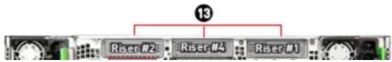
| Expansion Slots | • 3 x PCIe slots - RISER1: 1 xHHGen 3 (x16) - RISER2: 1 xHHGen 3 (x16) - RISER& 1 xHHGen 3 (x16) • 1 x OCP 3.0 mezzanine card slot | • 3 x PCIe slots - RISER1: 1 xHH Gen 4 (xf6) - RISER2: 1 xHH Gen 4 (x16) - RISER& 1 xHH Gen 3 (x16) • 1 x OCP 3.0 mezzanine card slot |
| Security | • TPM 2.0 • PFR (Optional) • Case intrusion switch | |
| Server Management | Aspeed AST2600 RPM: 2.0 with iKVM support | |
| Coding | • 2 x Passive CPU heatsink with air duct @205W | |
System Overview
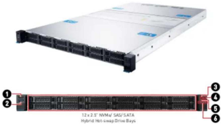
| 1 | USB 2.0 PortThis connector is provided for USB peripheral devices. (Speed up to 480 Mbps) | |||
| 2 | USB 3.2 Gen 1 PortThis connector is provided for USB peripheral devices. (Speed up to 5 Gbps) | |||
| 3 | System Power Button/ LED | |||
| 4 | UID Button/ LED | |||
| 5 | System Reset Button | |||
| 6 | System Status LEDNIC Link LEDsM.2 Activity LED | |||
| 7 | Power Supply Unit | |||
| 8 | VGA Port | |||
| 9 | RJ45 Serial Console Port | |||
| 11 | GbE RJ45 LAN Port (for Mgmt.)The standard RJ45 LAN jack is provided for connection to the Local Area Network (LAN). You can connect a network cable to it. | |||
LINK/ACT LED  | SPEED LED | LED | Status Description | |
| Link/ Activity LED | ○ Off No link | |||
| ● Green Linked | ||||
| ○ Blinking Data activity | ||||
| Speed LED | ○ Off 10 Mbps | |||
| ● Orange 100 Mbps | ||||
| ● Green 1 Gbps | ||||
| 12 | UID LED Button (or BMC Reset Button, configured using jumper: J1_5) | |||
| 13 | PCIe Add-in Card Area | |||
System LED Indicators
System Power Button/ LED
System Reset Button
! System Status LED
^1 NIC Link LED
UID Button/ LED
M.2 Activity LED
System Power LED
Blue
System power is on
System power is on ACPI S0 state
Blinking
System is sleeping
Off
System power is off
System power is on ACPI S4, S5 state
UID LED
Blue
Identify active via command or button
Off
No identification
! System Status LED
Green
BMC initialization
Red
System has failed
Off
System is running/ normal operation
^1 NIC Link LED
Green
NIC link is established
Blinking
NIC activity is occurring
Off
NIC link is not established
M.2 Activity LED
Green
M.2 present, no activity
Blinking
M.2 accessing
Off
No M.2 activity
Motherboard Overview
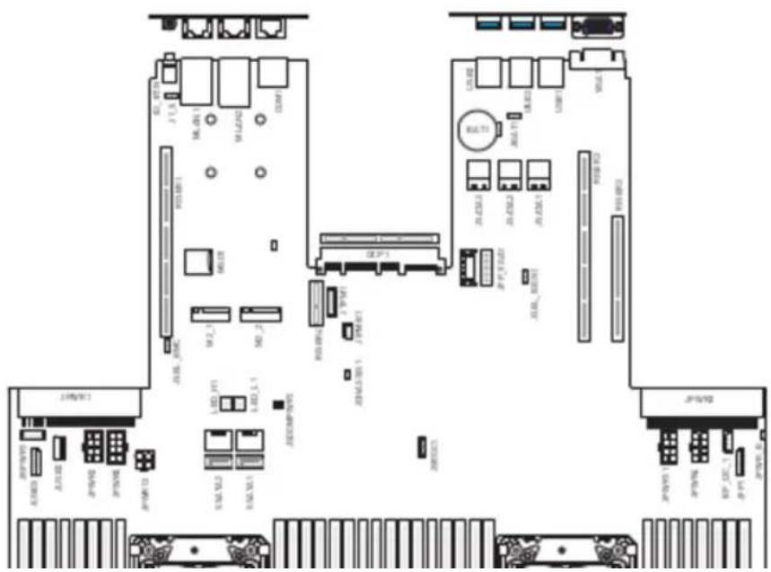
Motherboard Connectors
Power Connectors
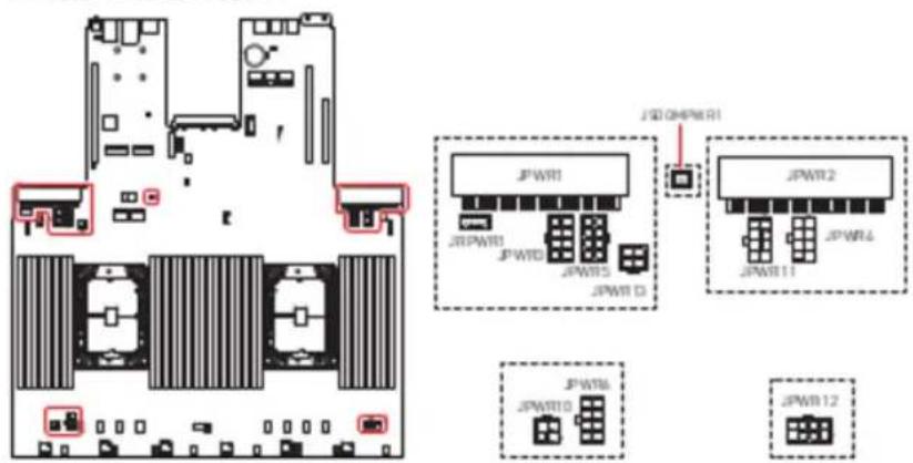
JPWR1\~2: CRPS Power Connectors
These CRPS (Common Redundant Power Supplies) connectors allow you to connect a power supply. To connect the power supply, ensure that the plug is inserted in the proper orientation and that the pins are aligned. Then firmly push down the power supply into the connector.
JPWR3-5. JPWR11: GPU Power Connectors
JPWR10: HDD BP Power Connector (Transparent)
This connector provides power output to HDD backplane.
JPWR 10 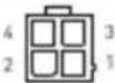 | 1 | GND | 2 | GND |
| 3 | P12V | 4 | P3V3 |
JPWR13: Fan Power Connector (Black)
This connector provides power output to fans.
| JPWR13 | 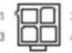 | 1 | OND | 2 | OND |
| 3 | P12V | 4 | P12V |
JRPWR1: HDD Power Connectors
These connectors provide power output to HDDs.
JRPWR1 ! 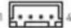 | 1 | PSV |
| 2 | OND | |
| 3 | OND | |
| 4 | P12V |
JSDOMPWR1: SATA DOM Power Connector
This connector is used to provide power to SATA DOM devices.
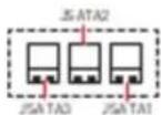
Storage Connectors

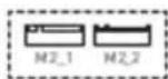
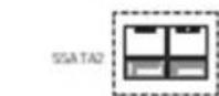
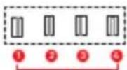
| Connector | Storage Specifications |
| SSATA 1~2 | SATA 6Gb/s |
| JSATA1~3 | SATA 6Gb/s |
| M2_1~2 | PCIe 3.0 x 2 8GT/s |
| JNVME1_1-4 | PCIe 3.0 x 4 8GT/s (S1201b) |
| JNVME2_1-4 | PCIe 4.0 x 4 16GT/s (S1201b-HE) |
3 JNME1,2
JNME1]
3 JNME13
JNME1.6
① JNME2.2
2 JNME2_1
3 JNME2_3
B.2019E2_4
JSATA1-3: Slimline SAS 4i Connectors
These connectors provide storage support for SATA devices.
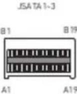 | A1 | GND | B1 | GND |
| A2 | JSATA_P0_RX+ | B2 | JSATA_P0_TX+ | |
| A3 | JSATA_P0_RX- | B3 | JSATA_P0_TX- | |
| A4 | GND | B4 | GND | |
| A5 | JSATA_P1_RX+ | B5 | JSATA_P1_TX+ | |
| A6 | JSATA_P1_RX- | B6 | JSATA_P1_TX- | |
| A7 | GND | B7 | GND | |
| A8 | BP_TYPE | B8 | SGPIO_SATA_CLOCK_R | |
| A9 | SGPIO_SATA_DATACUT_R | B9 | SGPIO_SATA_LOAD_R | |
| A10 | GND | B10 | GND | |
| A11 | NC | B11 | P3VG | |
| A12 | NC | B12 | NC | |
| A13 | GND | B13 | GND | |
| A14 | JSATA_P2_RX+ | B14 | JSATA_P2_TX+ | |
| A15 | JSATA_P2_RX- | B15 | JSATA_P2_TX- | |
| A16 | GND | B16 | GND | |
| A17 | JSATA_P3_RX+ | B17 | JSATA_P3_TX+ | |
| A18 | JSATA_P3_RX- | B18 | JSATA_P3_TX- | |
| A19 | GND | B19 | GND |
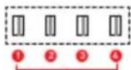
JNVME1\_1\~4, JNVME2\_1\~4: Slimline SAS 4i Connectors
These connectors provide storage support for PCIe NVMe devices.
JNVME1_1-4JNVME2_1-4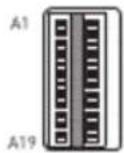 B1B19 B1B19 | A1 | GND-12 | B1 | GND-1 |
| A2 | ROP0 | B2 | TX0+ | |
| A3 | RXN0 | B3 | TX0- | |
| A4 | GND-11 | B4 | GND-2 | |
| A5 | ROP1 | B5 | TX1+ | |
| A6 | RXN1 | B6 | TX1- | |
| A7 | GND-10 | B7 | GND-3 | |
| A8 | SB7 | B8 | SB0 | |
| A9 | SB3 | B9 | SB1 | |
| A10 | SB9 | B10 | SB8 | |
| A11 | SB4 | B11 | SB2 | |
| A12 | SB5 | B12 | SB6 | |
| A13 | GND-9 | B13 | GND-4 | |
| A14 | RX2+ | B14 | TX2+ | |
| A15 | RX2- | B15 | TX2- | |
| A16 | GND-8 | B16 | GND-5 | |
| A17 | RX3+ | B17 | TX3+ | |
| A18 | RX3- | B18 | TX3- | |
| A19 | GND-9 | B19 | GND-4 |
FPC Connectors
A Flexible Printed Circuit (FPC) connector connects a flexible printed circuit or flat ribbon cable to a PCB. FPC connectors are also referred to as flat flexible cable (FFC) connectors or ribbon connectors. Their slim and lightweight design makes them ideal for electronic devices and equipment that require space-saving solutions.
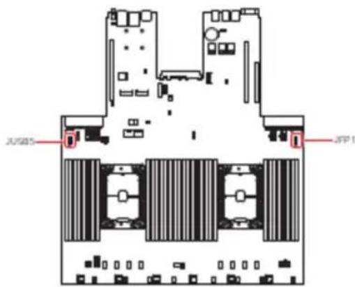
JFP1: Front Panel FPC Connector
The front panel connector is provided for electrical connection to the front panel switches and LEDs.
JUSB5: USB 3.2 Gen 1 FPC Connector
This port is backward-compatible with USB 2.0 devices and supports data transfer rate up to 5 Gbps.
| JUSBS1 | 24 | 1 | PSV_AUX_USB_BP6 | 14 | GND |
| 2 | PSV_AUX_USB_BP6 | 15 | USB3_P04_ESD_RXN | ||
| 3 | PSV_AUX_USB_BP6 | 14 | USB3_P04_ESD_RXP | ||
| 4 | PSV_AUX_USB_BP6 | 17 | GND | ||
| 5 | PSV_AUX_USB_BP6 | 18 | USB3_P04_ESD_TXN | ||
| 6 | PSV_AUX_USB_BP6 | 19 | USB3_P04_ESD_TXP | ||
| ? | GND | 20 | GND | ||
| 8 | GND | 21 | USB2_P04_ESD_ON | ||
| 9 | GND | 22 | USB2_P04_ESD_DIP | ||
| 10 | GND | 23 | GND | ||
| 11 | GND | 24 | USB2_P05_ESD_ON | ||
| 12 | GND | 25 | USB2_P05_ESD_DIP | ||
| 13 | GND | 26 | GND |

Important
- Note that the pins of VCC and GND must be connected correctly to avoid possible damage.
- To use a USB 3.2 device, you must connect the device to a USB 3.2 port through an optional USB 3.2 compliant cable.
Fan Connectors
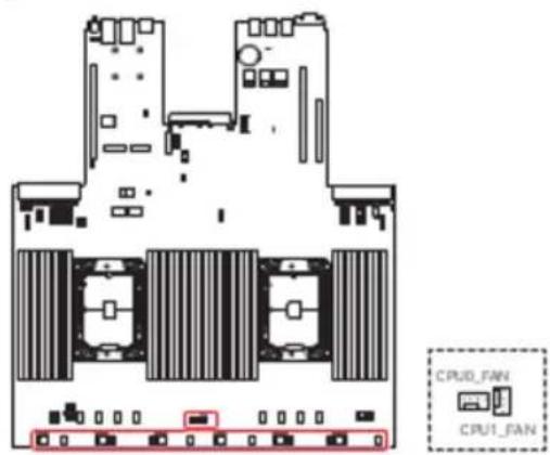
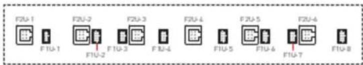
F2U1\~6: 2U System Fan Connectors
The fan power connectors support 2U system cooling fans.

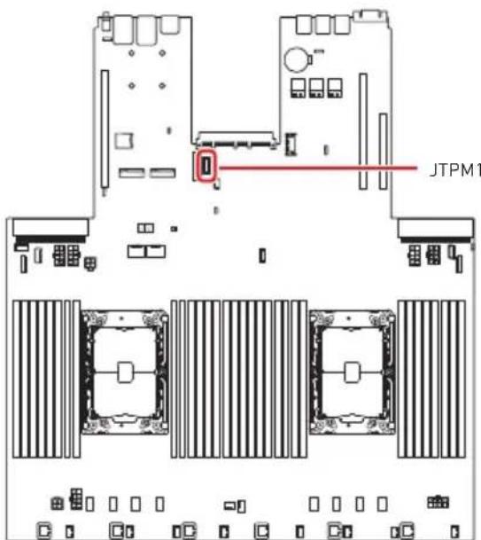
Other Connectors and Headers
JTPM1: SPI TPM Module Box Header
This connector connects to a TPM (Trusted Platform Module) module (optional). Please refer to the TPM security platform manual for more details.
JTPM120 19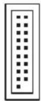 2 3 2 3 | 1 | N/A | 2 | SPI_CS0#_R |
| 3 | RST_RSMRST_N | 4 | N/A | |
| 5 | GND | 6 | P3V3_P1V8_PCH_SPI_AUX | |
| 7 | SPI_CLK_R | 8 | SPI_PCH_IO2 | |
| 9 | SPI_PCH_IO3 | 10 | SPI_MISO_R | |
| 11 | N/A | 12 | SPI_MOSI_R | |
| 13 | SPI_PCH_TPM_DEDIPROG_CS_N | 14 | GND | |
| 15 | P3V3_P1V8_PCH_SPI_AUX | 16 | N/A | |
| 17 | IRQ_TPM_SPI_N | 18 | P3V3_P1V8_PCH_SPI_AUX | |
| 19 | RST_PLTRST_B_N | 20 | P3V3_P1V8_PCH_SPI_AUX |
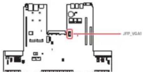
JFP\_VGA1: Front VGA Header
The VGA connector is provided for monitors.
JFP_VGA1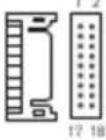 | 1 | N/A | 2 | N/A |
| 3 | F_RED | 4 | OND | |
| 5 | F_ORN | 4 | OND | |
| 7 | F_BLU | 8 | OND | |
| 9 | F_VS | 10 | OND | |
| 11 | F_HS | 12 | OND | |
| 13 | F_DOODAT | 14 | SEL_PP_N | |
| 15 | F_DOOCLK | 16 | F_WOA_SV | |
| 17 | N/A | 18 | N/A |
JUSB3: USB 3.2 Gen 1 Type-A Connector
The USB (Universal Serial Bus) port is for attaching USB devices such as keyboard, mouse, or other USB-compatible devices. It supports up to 5 Gbps data transfer rate.
儿(58)

JCHASSIS1: Chassis Intrusion Header
This connector connects to the chassis intrusion switch cable. If the chassis is opened, the chassis intrusion mechanism will be activated. The system will record this status and show a warning message on the screen. To clear the warning, you must enter the BIOS utility and clear the record.
JOHASSIS1

Trigger the chassis intrusion event

Normal. (Default)
JVROC1: VROC Box Header
Intel® Virtual RAID on CPU (Intel® VROC) is a hybrid RAID solution specifically designed for NVMe SSDs connected directly to the CPU.
JVRC1 1  4 4 | 1 | OND |
| 2 | PU_KEY_CONN_PIN2_R | |
| 3 | OND | |
| 4 | FM_PCH_SATA_RAD_KEY_R |
JIPMB1: IPMB Box Header
This connector is used to connect the IPMB (Intelligent Platform Management Bus).
| JIPMB1 | 1(2H28) | 1 | SMB_IPMB_SVSB_DAT |
| 2 | OND | ||
| 3 | SMB_IPMB_SVSB_CLK |
BP\_I2C\_1: I2C Box Headers
I2C connectors are used to connect to the System Management Bus (SMBus).
| BP_I2C_1 | [724X] | 1 | P2N3 |
| 2 | FP_I2C_CLK1 | ||
| 3 | FP_I2C_DAT1 | ||
| 4 | GND |
JPWR\_B: Front Power Button Header
This connector is provided to connect the front power button.
| JPWR_B | CATC | 1 | FP_PWR_BTN_R_N |
| 2 | OND |
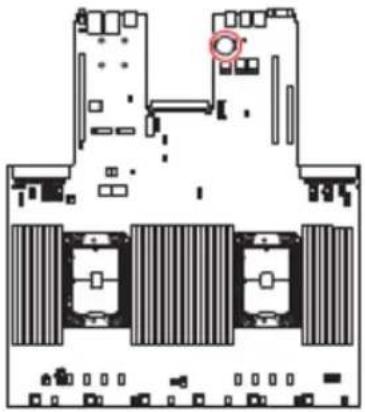
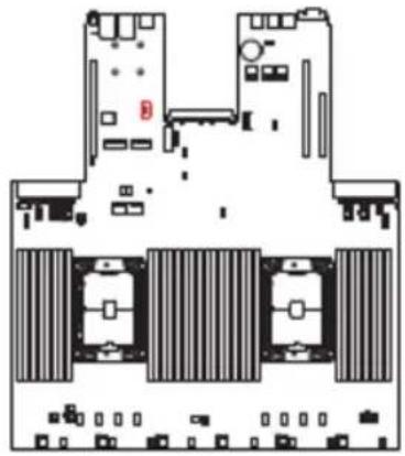
BAT1: CMOS Battery
If the CMOS battery is out of charge, the time in the BIOS will be reset and the data of system configuration will be lost. In this case, you need to replace the CMOS battery.
natural_image
Floor plan diagram of a computer room with multiple slots and a highlighted circular area (no text or labels)Replacing CMOS battery
- Push the retainer clip to free the battery.
- Remove the battery from the socket.
- Install the new CR2032 coin-cell battery with the + sign facing up. Ensure that the retainer holds the battery securely.
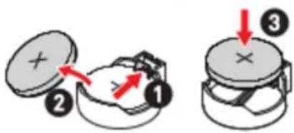

WARNING
KEEP OUT OF REACH OF CHILDREN
- Swallowing can lead to chemical burns, perforation of soft tissue, can death.
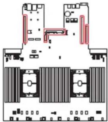
Motherboard Expansion Slots
natural_image
Architectural floor plan showing room layouts and structural elements (no text or labels)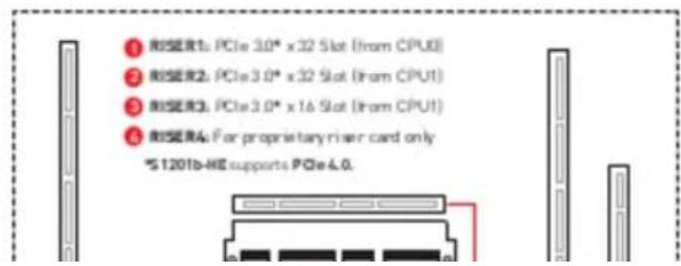
Motherboard Jumpers

Important
Avoid adjusting jumpers when the system is on; it will damage the motherboard.
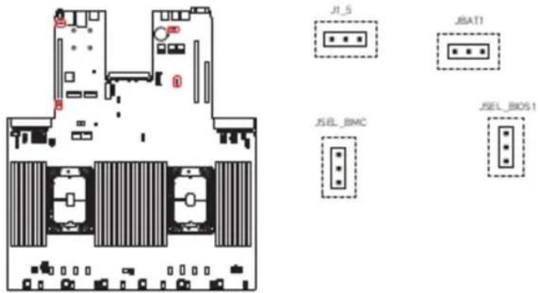
| Jumper Name | Default Setting | Description |
| ■ 1 | 1-2: Using BIOS1 [Default] |
Onboard LEDs
BMC Heartbeat LED
This LED indicates the BMC (Baseboard Management Controller) status.
natural_image
Top-down schematic of a multi-chambered electronic device layout (no text or symbols)| Status | Description |
| Off | BMC is not activated |
| Blinding | BMC is functioning normally |
LED\_H1, LED\_L1: Port 80 Debug LEDs
The Port 80 debug LEDs display progress and error codes during and after POST [Power-On Self Test].
Getting Started

All information is subject to change without prior notice.
The system illustrations are for demonstration purpose only. Actual system appearance and components may vary depending on your specific model.
Necessary Tools
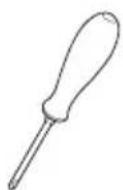
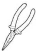
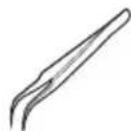

natural_image
Line drawing of two human gloves (no text or symbols)Screwdriver Pliers Tweezers Anti-Static Gloves
Safety Precautions
The following precautions should be observed while handling the system:
- Place the system on a flat and stable surface.
- Do not place the system in environments subject to mist, smoke, vibration, excessive dust, salty or greasy air, or other corrosive gases and fumes.
- Do not drop or jolt the system.
- Do not use a power adapter other than the one enclosed with the system.
- Disconnect the power cord before performing any installation procedures on the system.
- Do not perform any maintenance with wet hands.
- Prevent foreign substances, such as water, other liquids or chemicals, from entering the system while performing installation procedures.
- Use a grounded wrist strap before handling system components such as CPU, Memory, HDD, expansion cards, etc.
- Place system components on a grounded anti-static pad or on the bed that came with the components whenever the components are separated from the system.
System Setup

Important
Before removing or installing any components, make sure the system is not turned on or connected to the power.
Drive Bay
Installing 2.5" HDD/SSD
- Press the tray button to release the lever.
- Pull the HDD/ SSD assembly out of the drive bay.
- Insert the HDD/SSD horizontally.
• The interposer BKT act as dummy HDD/SSD when no drive inside.
• The interposer BKT act as spacer to support 7nm HOD/SSD.
System Cover
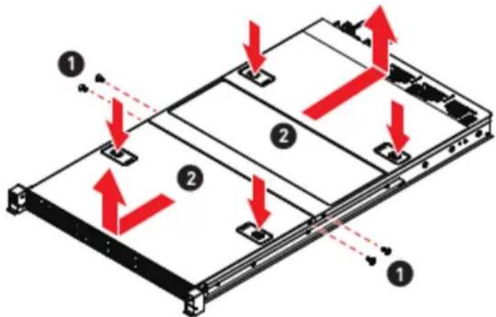
Removing System Cover
- Remove the screws securing the system on both sides.
- To remove the top cover panels, press down on the release latches on both sides and then slide them to the front or back side of the system.
CPU & Heatsink
Use appropriate ground straps, gloves and ESD mats to protect yourself from electrostatic discharge (ESD) while installing the processor.

Important
Images are for illustration purposes only; actual parts may vary.
Assembly Overview
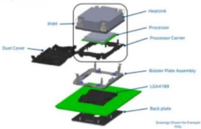
Installing CPU & Heatsink
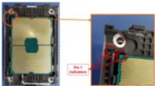
- Check the CPU and the processor carrier for their Pin 1 indicators.
- Align their Pin 1 indicators before inserting the CPU into the processor carrier. If installed properly, the CPU will snap into the side snap latches on the carrier and the carrier will latch firmly to the processor.
- Remove the protective film on the base of heatsink if any.
- Align Pin 1 indicator of processor carrier and the corner cutout of the heatsink. Gently press the heatsink down to engage the carrier's latching mechanism to the heatsink at four corners. A clicking sound will be heard when latched properly.
- Verify that the carrier and heatsink are firmly latched as one Processor Heatsink Module.
- Place the Processor Heatsink Module on top of the motherboard CPU socket with Pin 1 indicators aligned.
- Tighten all screws on the Processor Heatsink Module in diagonal sequences to
Memory
natural_image
Pure horizontal lines without any text, numbers, or symbols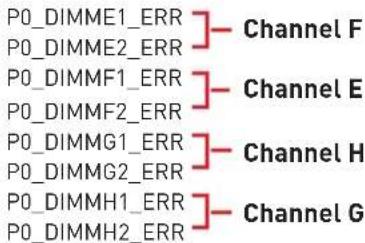
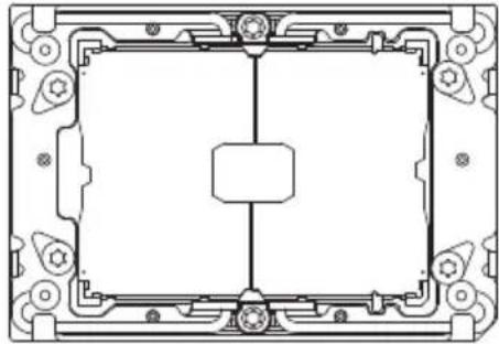
natural_image
Pure technical line drawing of a mechanical or architectural component without any text, numbers, or symbolsCPU1_ILM1

natural_image
Blank white rectangular fields with no text, numbers, or symbols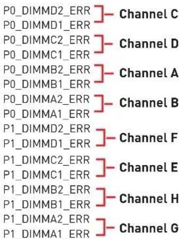
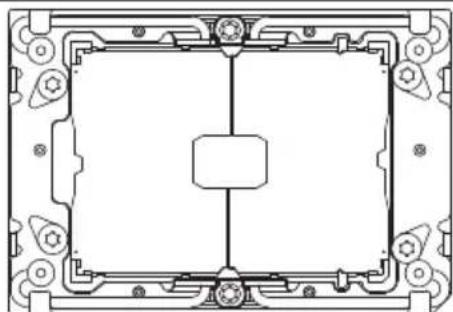
natural_image
Pure technical line drawing of a mechanical or architectural component with no text, numbers, or symbolsCPU2_ILM1
natural_image
Pure horizontal lines without any text, numbers, or symbols![P1_DIMMH2_ERR ] Channel C P1_DIMMH1_ERR ] P1_DIMMG2_ERR ] Channel D P1_DIMMG1_ERR ] P1_DIMMF2_ERR ] Channel A P1_DIMMF1_ERR ] P1_DIMME2_ERR ] Channel B P1_DIMME1_ERR ]](/content/2026/05/1065391/images/7b6766216090235ee8a40b2cdddb73843d627d5b5f2d89c1b25a6b81379b545f.jpg)
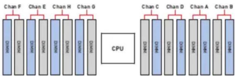
flowchart
graph TD
    subgraph CPU
        A1["CHAN F"] --> B1["CPU"]
        A2["CHAN E"] --> B2["CPU"]
        A3["CHAN H"] --> B3["CPU"]
        A4["CHAN G"] --> B4["CPU"]
    end
    subgraph Output
        C1["CHAN C"] --> D1["CPU"]
        C2["CHAN D"] --> D2["CPU"]
        C3["CHAN A"] --> D3["CPU"]
        C4["CHAN B"] --> D4["CPU"]
    end
Mixing of DIMM Types within a Channel
| DIMM Types | RDIMM | 3DS RDIMM | LRDIMM | 3DS LRDIMM | PMem module |
| RDIMM | A | N/A | N/A | N/A | A |
| 3DS RDIMM | N/A | A | N/A | N/A | A |
| LRDIMM | N/A | N/A | A | N/A | A |
| 3DS LRDIMM | N/A | N/A | N/A | A | A |
| Intel® OptaneTMPMem 200series DIMM | A | A | A | A | N/A |
| "A" means DIMMs are allowed to mix populations in a channel; "N/A" means not allowed to do so. | |||||
Recommended Memory Population
DDR4 Only (1LM Mode)
| SlotDIMMs | Chan F | Chan E | Chan H | Chan G | Chan C | Chan D | Chan A | Chan B | ||||||||
| Channel 1 | Channel 0 | Channel 1 | Channel 0 | Channel 0 | Channel 1 | Channel 0 | Channel 1 | |||||||||
| D11 | D12 | D9 | D10 | D15 | D16 | D13 | D14 | D6 | D5 | D8 | D7 | D2 | D1 | D4 | D3 | |
| 1 | V | |||||||||||||||
| V | ||||||||||||||||
| V | ||||||||||||||||
| V | ||||||||||||||||
| V | ||||||||||||||||
| V | ||||||||||||||||
| V | ||||||||||||||||
| V | ||||||||||||||||
| 2 | V | V | ||||||||||||||
| V | V | |||||||||||||||
| V | V | |||||||||||||||
| V | V | |||||||||||||||
| V | V | |||||||||||||||
| V | V | |||||||||||||||
| V | V | |||||||||||||||
| 4 | V | V | V | V | ||||||||||||
| V | V | V | V | |||||||||||||
| V | V | V | V | |||||||||||||
| V | V | V | V | |||||||||||||
| 6 | V | V | V | V | V | V | ||||||||||
| V | V | V | V | V | V | |||||||||||
| V | V | V | V | V | V | |||||||||||
| V | V | V | V | V | V | |||||||||||
| 8 | V | V | V | V | V | V | V | V | ||||||||
DDR4 + Intel® Optane™ Persistent Memory 200 Series
| Mode | DDR6+BPS | ChanF | Chan E | Chan H | Chan G | Chan C | Chan D | Chan A | Chan B | ||||||||
| CH 1 | CH 0 | CH 1 | CH 0 | CH 0 | CH 1 | CH 0 | CH 1 | ||||||||||
| D11 | D12 | D9 | D10 | D15 | D16 | D13 | D14 | D6 | D5 | D8 | D7 | D2 | D1 | D6 | D3 | ||
| 1LM+AD,MM | 4+6 | 0 | V | 0 | V | V | 0 | V | 0 | ||||||||
| V | 0 | V | 0 | 0 | V | 0 | V | ||||||||||
| 1LM+AD | 6+1 | V | V | V | V | 0 | V | V | |||||||||
| V | V | V | V | V | V | 0 | |||||||||||
| V | V | 0 | V | V | V | V | V | ||||||||||
| 0 | V | V | V | V | V | V | |||||||||||
| V | V | V | 0 | V | V | V | |||||||||||
| V | V | V | V | V | 0 | V | |||||||||||
| V | V | V | 0 | V | V | V | |||||||||||
| V | 0 | V | V | V | V | V | |||||||||||
| 8+1 | V | V | V | V | V | V | 0 | V | V | ||||||||
| V | V | V | V | 0 | V | V | V | ||||||||||
| V | V | 0 | V | V | V | V | V | V | |||||||||
| V | V | V | V | 0 | V | V | V | V | |||||||||
| V | V | V | V | V | 0 | V | V | V | |||||||||
| V | V | V | V | V | V | V | 0 | V | |||||||||
| V | 0 | V | V | V | V | V | V | V | |||||||||
| V | V | V | 0 | V | V | V | V | V | |||||||||
| 1LM+AD,MM | 8+4 | V | V | 0 | V | V | 0 | 0 | V | V | 0 | V | |||||
| V | V | 0 | V | 0 | V | V | 0 | V | 0 | V | V | ||||||
| V | 0 | V | V | V | 0 | 0 | V | V | V | 0 | |||||||
| V | 0 | V | V | 0 | V | V | 0 | V | V | 0 | V | ||||||
| 8+8 | V | 0 | V | 0 | V | 0 | V | 0 | 0 | V | 0 | 0 | V | 0 | V | ||
| 1LM+AD | 12+2 | 0 | V | V | V | V | V | V | V | V | V | V | V | 0 | |||
| V | V | V | V | 0 | V | V | V | V | 0 | V | V | V | |||||
| V | V | 0 | V | V | V | V | V | V | V | 0 | V | V | |||||
| 0 | 0 | 0 | 0 | 0 | 0 | 0 | 0 | 0 | 0 | 0 | 0 | 0 | 0 | 0 | |||
Installing Memory Modules
- Open the side clips to unlock the DIMM slot.
- Insert the DIMM vertically into the slot, ensuring that the off-center notch at the bottom aligns with the slot.
- Push the DIMM firmly into the slot until it clicks and the side clips automatically close.
- Verify that the side clips have securely locked the DIMM in place.
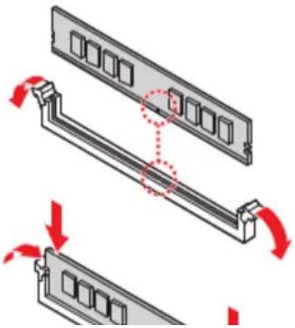
natural_image
Diagram showing three views of a computer RAM module with red arrows indicating rotation and movement (no text or symbols)M.2 M Key
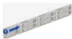
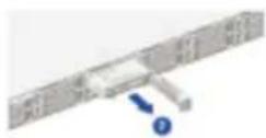
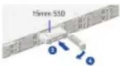
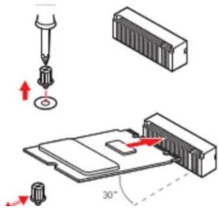
Installing M.2 SSD

Video Demonstration
Watch the video to learn how to install M.2 SSD.

-
Loosen the M.2 riser screw from the mother board.
-
Move and fasten the M.2 riser screw to the appropriate location according your M.2 SSD size.
-
Insert your M.2 SSD into the M.2 slot at a 30-degree angle.
PCIe Add-in Card
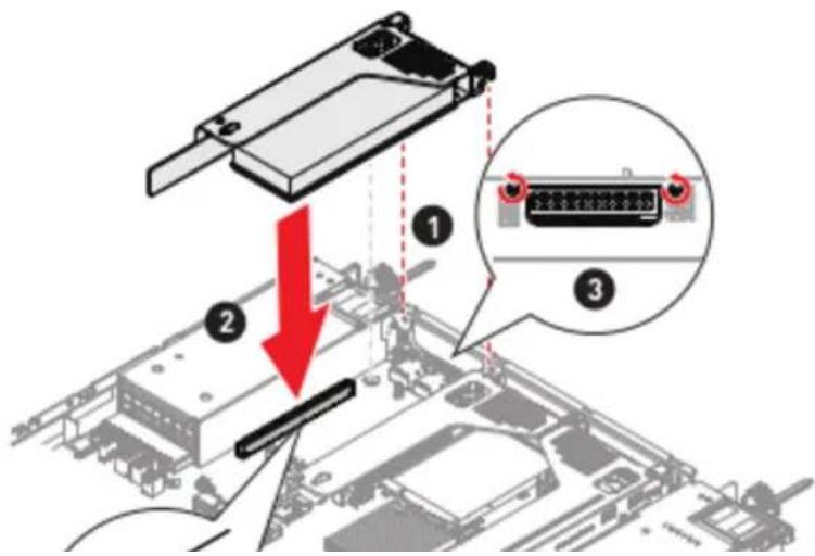
Installing PCIe Add-in Card
- Loosen the screws on the riser bracket to remove the filler panels.
- Align the PCIe add-in card with the connector on the riser card, and insert it until it is fully seated.
- Tighten the screws to securely fix the PCIe add-in card in place.

important
The procedure for installing PCIe add-in cards are the same for all riser slots.
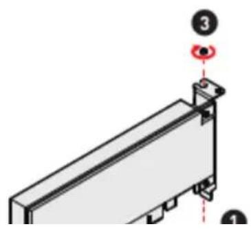
natural_image
3D diagram of a mechanical component with a numbered indicator (3) and a red circular symbol, no readable text or labels present.Installing Riser Card Assembly
- Lower the riser card assembly down as shown in the image below.
- Insert the riser card assembly into the PCIe slot on the system board.
- Tighten the screws on the rear side of the system to secure the riser card assembly.
System Fan
The server system is equipped with 8 non-hot swappable system fans that measure 40 x 40 x 56mm, which provide primary airflow to maintain optimal cooling and prevent over heating.
The fan features include:
- Tachometer on each fan allows BMC to monitor the system's status in real-time.
- An integrated BMC firmware automatically adjusts fan speed based on the system's thermal status to maintain optimal performance.
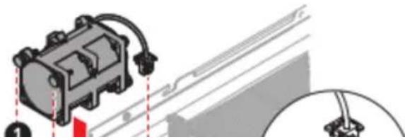
Installing 1U Fan
- Lower the system fan until it seated firmly.
- Connect the fan cable to the system board.
- Note the fool-proof design on the connector before docking it.
natural_image
Mechanical assembly diagram showing a motor connected to a cable (no text or symbols visible)Power Supply Unit (PSU)
The server system supports two power supplies that can be easily inserted and removed from the rear side of the system without the need for tools.

Important
- Both power supplies must be identical and both power cards should be connected.
- Failing to connect both power supplies could result in CPU throttling.
Installing PSU
- Remove the PSU blank.
- Slide the PSU into the chassis bay until the release latch snaps into place.
- Connect the power cable to the PSU power outlet.
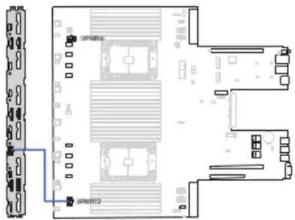
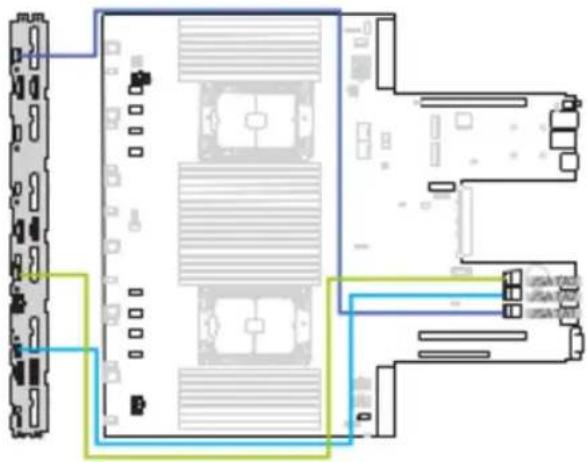
Cable Routing

Important
Please remove the fan cage before routing cables.
8-pin to 8-pin Power Cable
SlimlineSAS 4i to SlimlineSAS 4i Cable (for SATA)
natural_image
Diagram of a server rack with multiple ports and connections, no text or symbols presentSlimlineSAS 4i to SlimlineSAS 8i Cable (for NVMe)
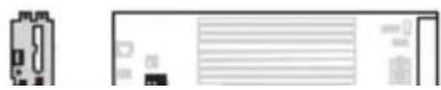
SlimlineSAS 8i to SlimlineSAS 8i Cable
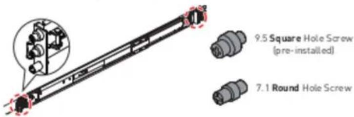
Slide Rail

Important
The pre-installed screws on the outer rail bracket are intended only for square rack holes. For round holes, please switch to the "7.1 round hole screw".
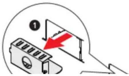
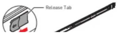
Disassembling Slide Rail
Slide the release tab forward to separate the inner rail from the bracket.
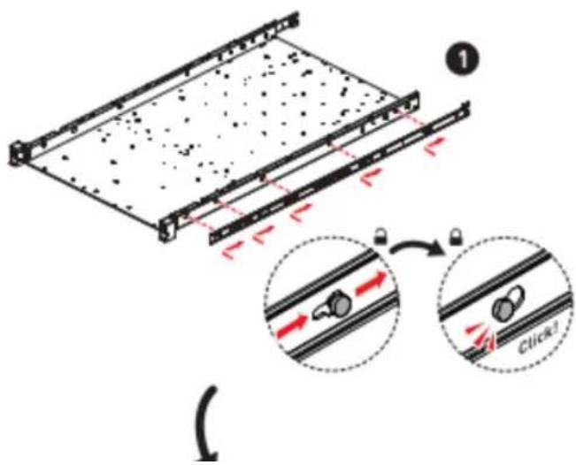
Installing Inner Rail to System
- Align the standoffs on the side of the system with the hole on the inner rail, then pull the inner rail backwards till it locks into place.
- Tighten the screw to secure the inner rail.
- Repeat the same procedure to install the inner rail on the other side of the system.
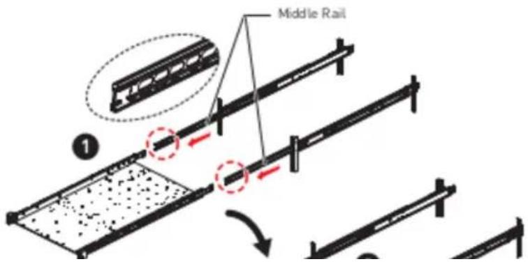
Retracting Outer Rail Bracket
Pull the latch downward to slide the middle rail back to the outer rail bracket.

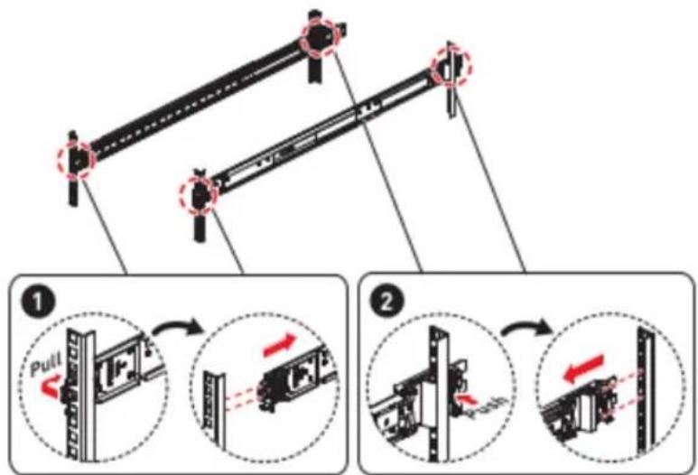
Attaching Outer Rail Bracket to Rack Frame
natural_image
Diagram of two mechanical components with alignment pins, no visible text or symbolsInstalling System into Rack
- Pull out the middle rails till it fully extended.
- Engage the inner rails of the system to the middle rails, then push the system forward until it stops.
- Push the system into the rack by sliding the two-way release tabs forward or backward.
- Tighten the screws to secure the system.

Important
Ensure the ball bearing retainers are locked forward on each middle rail.
Detaching Outer Rail Bracket from Rack Frame
Detaching Inner Rail from System

bar
| Category | Value | |---|---| | Category 1 | 100 | | Category 2 | 100 | | Category 3 | 100 | | Category 4 | 100 | | Category 5 | 100 | | Category 6 | 100 | | Category 7 | 100 | | Category 8 | 100 | | Category 9 | 100 | | Category 10 | 100 |- Regulatory Notices
- WEEE Statement
- Chemical Substances Information
- CE Conformity
- FCC-A Radio Frequency Interference Statement
- Notice 1
- Notice 2
- Battery Information
- European Union:
- BSMI:
- 廢電池請回收
- California, USA:
- Safety Information
- System LED Indicators
- Motherboard Connectors
- JPWR1\~2: CRPS Power Connectors
- JPWR10: HDD BP Power Connector (Transparent)
- JPWR13: Fan Power Connector (Black)
- JRPWR1: HDD Power Connectors
- JSDOMPWR1: SATA DOM Power Connector
- JSATA1-3: Slimline SAS 4i Connectors
- JNVME1\_1\~4, JNVME2\_1\~4: Slimline SAS 4i Connectors
- FPC Connectors
- JFP1: Front Panel FPC Connector
- JUSB5: USB 3.2 Gen 1 FPC Connector
- Important
- Other Connectors and Headers
- JTPM1: SPI TPM Module Box Header
- JFP\_VGA1: Front VGA Header
- JUSB3: USB 3.2 Gen 1 Type-A Connector
- JCHASSIS1: Chassis Intrusion Header
- JVROC1: VROC Box Header
- JIPMB1: IPMB Box Header
- BP\_I2C\_1: I2C Box Headers
- JPWR\_B: Front Power Button Header
- BAT1: CMOS Battery
- Replacing CMOS battery
- WARNING
- KEEP OUT OF REACH OF CHILDREN
- Motherboard Jumpers
- Onboard LEDs
- BMC Heartbeat LED
- LED\_H1, LED\_L1: Port 80 Debug LEDs
- Getting Started
- Necessary Tools
- Safety Precautions
- System Setup
- Drive Bay
- Installing 2.5" HDD/SSD
- System Cover
- Removing System Cover
- CPU & Heatsink
- Installing CPU & Heatsink
- Memory
- Recommended Memory Population
- Installing Memory Modules
- M.2 M Key
- PCIe Add-in Card
- Installing PCIe Add-in Card
- Installing Riser Card Assembly
- System Fan
- The fan features include:
- Installing 1U Fan
- Power Supply Unit (PSU)
- Installing PSU
- Cable Routing
- Slide Rail
- Disassembling Slide Rail
- Installing Inner Rail to System
- Retracting Outer Rail Bracket
- Installing System into Rack
Brand : MSI
Model : S1201
Category : Server