
G3101 - Server MSI - Free user manual and instructions
Find the device manual for free G3101 MSI in PDF.

| Product Type | Rackmount Server |
| Form Factor | 1U |
| Dimensions (W x D x H) | 17.2 x 24 x 1.7 inches |
| Weight | 22 lbs (10 kg) |
| Processor Support | Dual Intel Xeon Scalable 3rd Gen |
| Memory | Up to 512 GB DDR4 ECC RDIMM |
| Storage Bays | 8 x 2.5" SATA/SAS hot-swap |
| RAID Support | Hardware RAID 0, 1, 5, 10 |
| Network Interfaces | 2 x 10GbE SFP+ |
| Power Supply | Dual Redundant 550W 80+ Gold |
| Management | IPMI 2.0, web-based remote console |
| Cooling | 4 x hot-swap fans |
| Operating Temperature | 10°C to 35°C |
| Certification | CE, FCC, RoHS |
| Main Functions | Enterprise server for virtualization, database, and cloud workloads |
| Care and Cleaning | Use compressed air to clean air vents; avoid liquids |
| Safety Precautions | Disconnect power before servicing; use anti-static wrist strap |
| Spare Parts Availability | Compatible memory, drives, PSUs, and fans available via MSI channel |
| Repairability | Tool-less access to internal components; field-replaceable units |
| Warranty | 3 years limited hardware warranty |
Frequently Asked Questions - G3101 MSI
User questions about G3101 MSI
0 question about this device. Answer the ones you know or ask your own.
Ask a new question about this device
Download the instructions for your Server in PDF format for free! Find your manual G3101 - MSI and take your electronic device back in hand. On this page are published all the documents necessary for the use of your device. G3101 by MSI.
USER MANUAL G3101 MSI
Regulatory Notices....3
Safety Information 5
System Overview 6
MS-S238....6
System Specifications 9
Motherboard Connector 10
Motherboard Jumper....14
Getting Started....15
Necessary Tools 15
Safety Precautions.... 15
System Setup....16
CPU 16
Memory 18
Supported Memory Population 19
M.2 Key M (Optional)....20
Hard Disk Drive (Optional) 21
Graphics Card (Optional).... 23
Air Cooler Module (Optional) 24
Water Cooler Module (Optional)....28
Revision
V1.1, 2023/07
Regulatory Notices
WEEE Statement
Under the European Union ("EU") Directive on Waste Electrical and Electronic Equipment, Directive 2012/19/EU, products of "electrical and electronic equipment" cannot be discarded as municipal waste anymore and manufacturers of covered electronic equipment will be obligated to take back such products at the end of their useful life.

Chemical Substances Information
In compliance with chemical substances regulations, such as the EU REACH Regulation (Regulation EC No. 1907/2006 of the European Parliament and the Council), MSI provides the information of chemical substances in products at:
https://csr.msi.com/global/index
CE Conformity
Hereby, Micro-Star International CO., LTD declares that this device is in compliance with the essential safety requirements and other relevant provisions set out in the European Directive.

FCC-A Radio Frequency Interference Statement
This equipment has been tested and found to comply with the limits for a Class A digital device, pursuant to Part 15 of the FCC Rules. These limits are designed to provide reasonable protection against harmful interference when the equipment is operated in a commercial environment. This equipment generates, uses and can radiate radio frequency energy and, if not installed and used in accordance with the instruction manual, may cause harmful interference to radio communications. Operation of this equipment in a residential area is likely to cause harmful interference, in which case the user will be required to correct the interference at his own expense.

Notice 1
The changes or modifications not expressly approved by the party responsible for compliance could void the user's authority to operate the equipment.
Notice 2
Shielded interface cables and AC power cord, if any, must be used in order to comply with the emission limits.
This device complies with Part 15 of the FCC Rules. Operation is subject to the following two conditions:
• This device may not cause harmful interference, and
- This device must accept any interference received, including interference that may cause undesired operation.
Battery Information
Please take special precautions if this product comes with a battery.
- Danger of explosion if battery is incorrectly replaced. Replace only with the same or equivalent type recommended by the manufacturer.
- Avoid disposal of a battery into fire or a hot oven, or mechanically crushing or cutting of a battery, which can result in an explosion.
- Avoid leaving a battery in an extremely high temperature or extremely low air pressure environment that can result in an explosion or the leakage of flammable liquid or gas.
- Do not ingest battery. If the coin/button cell battery is swallowed, it can cause severe internal burns and can lead to death. Keep new and used batteries away from children.
European Union:

Batteries, battery packs, and accumulators should not be disposed of as unsorted household waste. Please use the public collection system to return, recycle, or treat them in compliance with the local regulations.
BSMI:

廢電池請回收
For better environmental protection, waste batteries should be collected separately for recycling or special disposal.
California, USA:

The button cell battery may contain perchlorate material and requires special handling when recycled or disposed of in California.
For further information please visit: http://www.dtsc.ca.gov/hazardouswaste/perchlorate/
Copyright and Trademarks Notice
Copyright © Micro-Star Int'l Co., Ltd. All rights reserved. The MSI logo used is a registered trademark of Micro-Star Int'l Co., Ltd. All other marks and names mentioned may be trademarks of their respective owners. No warranty as to accuracy or completeness is expressed or implied. MSI reserves the right to make changes to this document without prior notice.
Technical Support
If a problem arises with your product and no solution can be obtained from the user's manual, please contact your place of purchase or local distributor. Alternatively, please visit https://www.msi.com/support/ for further guidance.
Safety Information
• Always read the safety instructions carefully.
- Keep this User's Manual for future reference.
- Keep this equipment away from humidity.
- Lay this equipment on a reliable flat surface before setting it up.
- The openings on the enclosure are for air convection hence protects the equipment from overheating. Do not cover the openings.
- Make sure the voltage of the power source and adjust properly before connecting the equipment to the power inlet.
- Place the power cord such a way that people can not step on it. Do not place anything over the power cord.
- Always unplug the power cord before inserting any add-on card or module.
- All cautions and warnings on the equipment should be noted.
- Never pour any liquid into the opening that could damage or cause electrical shock.
- If any of the following situations arises, get the equipment checked by service personnel:
• The power cord or plug is damaged.
• Liquid has penetrated into the equipment.
- The equipment has been exposed to moisture.
- The equipment does not work well or you can not get it work according to User's Manual.
• The equipment has dropped and damaged.
• The equipment has obvious sign of breakage.
- Do not leave this equipment in an environment unconditioned, storage temperature above 60°C (140°F), it may damage the equipment.
System Overview
MS-S238
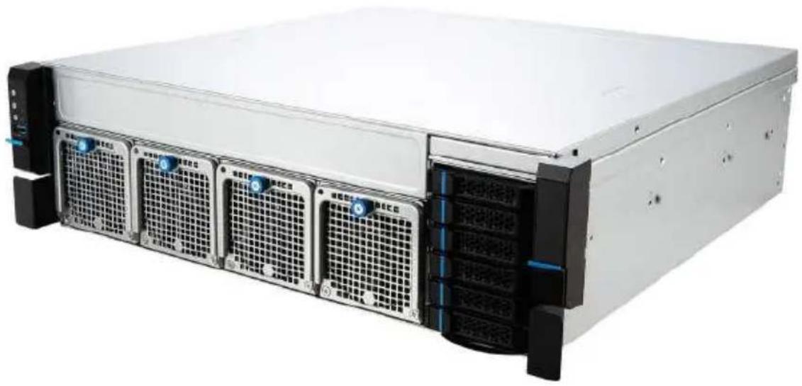
natural_image
Front view of a server rack with multiple drive bays and ventilation grilles (no visible text or labels)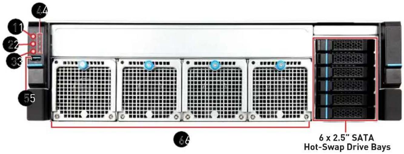
 |   |
 | [AKDS] |
 |   |
| [XA40] |  [TS00] [TS00] |
  | |
 [BYZO] [BYZO] | |
 | USB 2.0 PortThis connector is provided for USB peripheral devices. (Speed up to 480 Mbps) High-speed devices are recommended for USB 3.2 ports whereas low-speed devices, such as mouse or keyboard, are suggested to be plugged into the USB 2.0 ports. High-speed devices are recommended for USB 3.2 ports whereas low-speed devices, such as mouse or keyboard, are suggested to be plugged into the USB 2.0 ports. |
| [CXZB] | 8038 System Fans |
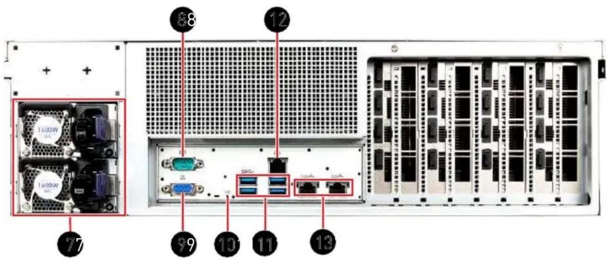
 | Power Supply Unit |
 | COM Port |
| [YCST] | VGA Port |
| [5330] | UID LED |
 | USB 3.2 Gen 1 PortThis connector is provided for USB peripheral devices. (Speed up to 5 Gbps) |
| 12 2 | GbE RJ45 Port (for Mgmt)The standard RJ45 LAN jack is provided for connection to the Local Area Network (LAN). You can connect a network cable to it. |
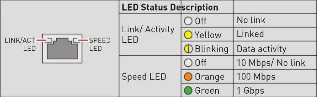 | |
| 13 | 10 GbE RJ45 PortThe standard RJ45 LAN jack is provided for connection to the Local Area Network (LAN). You can connect a network cable to it.1 GbE |
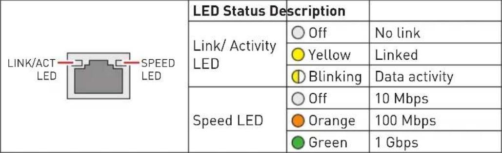 | |
| 10 GbE | |
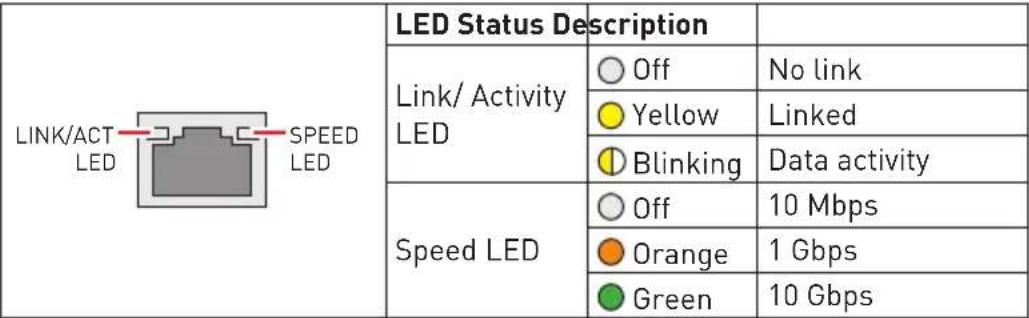 | |
| Depending on LAN chip capability. X710-AT2 does not support 100Mbps. |
System Specifications
| Model G3101 | |
| Dimensions 3U, 17.2"W (438mm) x 5.2"H (131mm) x 17.7"D (450mm) | |
| Processor Single AMD EPYCTM 7002/ 7003 Series Processors, up to 64C, TDP 300W | |
| Memory • 8 x DDR4 Max 2933/ 3200 Mhz- RDIMM/ LRDIMM/ 3DS up to 2TB | |
| Networking • 2 x 10 GbE RJ45 ports (Intel® X710AT2) w/ NCSI | |
| Expansion Slots • | 4 x PCIe 4.0 x16 for GPGPU• 3 x PCIe 4.0 x8 |
| Internal Storage 2 x M.2 M-key (2280/ 22110) | |
| Drive Bays 6 x 2.5" | SATA Hot-swap drive bays |
| Server Management | • Aspeed AST2500 IPMI2.0 with iKVM• 1 x GbE RJ45 Mgmt. port (Realtek RTL8211E-VB) |
| Cooling | • 1 x CPU air cooler module (240W) or 1 x CPU liquid cooler module (300W)• 4 x 80mm x 38mm PWM Hot-swap fans |
| Power Supply CRPS 1+1 hot-plug redundant PSU | |
| Environmental | • Operating Temperature: 0°C ~ 35°C (40°C w/liquid cooling)• Non-operating Temperature: -20°C ~ 70°C• Non-operating Relative Humidity: 5% ~ 85% (non-condensing) |
| Accessory 1 x Slide Rail (Optional) | |
| Certifications CE | FCC (Class A) |
Motherboard Connector
JPWR1, JPWR2, JPWR3: Power Connector
JPWR1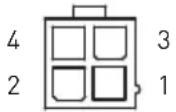 | 1 GND 2 GND | |||
| 3 | P12V | 4 | P12V | |
JPWR2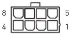 | 1 GND 2 GND | ||
| 3 GND 4 GND | |||
| 5 +12V 6 +12V | |||
| 7 +12V 8 +12V |
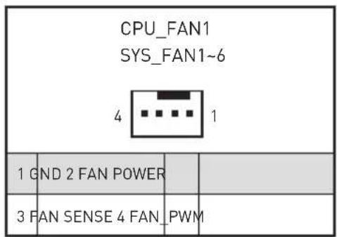
CPU_FAN1: CPU Fan Power Connectors
SYS_FAN1 \~ SYS_FAN6: System Fan Power Connectors
JFP1: Front Panel Header
JCHASSIS1: Chassis Intrusion Header
JVGA1:VGA Box Header
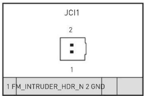

Normal (default)

Trigger the chassis intrusion event
| JFP1 24 | |||
| 1 | 23 | ||
| 1 PWR_LED+ 2 FP_PWR | |||
| 3 NA 4 SYS_ID_LED+ | |||
| 5 PWR_LED- 6 SYS_ID_LED- | |||
| 7 HDD_ACT_LED+ 8 SYS_FAULT_LED1- | |||
| 9 | HDD_ACT_LED- | 10 SYS_FAULT_LED2- | |
| 11 | PWR_BTN | 12 NIC#1_ACT_LED+ | |
| 13 | PWR_BTN_GND | 14 NIC#1_ACT_LED- | |
| 15 | RST_BTN | 16 | SMB_SDA |
| 17 | RST_BTN_GND | 18 | SMB_SCL |
| 19 | SYS_ID_BTN 20 CHASSIS_INTRUSION | ||
| 21 WIRE_TEMP_SENSOR 22 NIC#2_ACT_LED+ | |||
| 23 | NMI_BTN 24 | NIC#2_ACT_LED- | |
| JVGA1 13 14 | |||
| 1 | F_RED | 2 SEL_FP_N | |
| 3 | F_GRN | 4 | GND |
| 5 | F_BLU | 6 | GND |
| 7 | GND | 8 | F_VGA_5V |
| 9 | GND | 10 | DDCCLK |
| 11 | F_HS | 12 | F_VS |
| 13 | DDCDAT | 14 | NA |
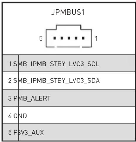
JPMBUS1: PMBUS Box Header
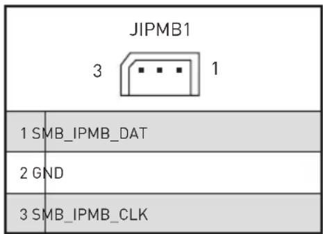
IPMB1: IPMB Box Header
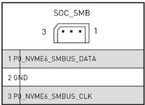
SOC_SMB: SOC SMB Box Header
JCOM2: COM Port Header
SGPIO Box Header: JSGPIO1
| JCOM2 2 1 | 10 9 | |||||
| 1 CONB_DCD 2 CONB_RXD | ||||||
| 3 CONB_TXD 4 CONB_DTR | ||||||
| 5 GND 6 CONB_DSR | ||||||
| 7 CONB_RTS 8 CONB_CTS | ||||||
| 9 CONB_RI 10 NA | ||||||
| JSGPIO1 | |||
| 17 18 2 | |||
| 1 | SGPIO_BMC_CLK | 2 2_5HD_SEL | |
| 3 | SGPIO_BMC_LD_N | 4 | RST_PLTRST_N |
| 5 | SGPIO_BMC_DIN | 6 | GLOBAL_ACTIVE_N |
| 7 | SGPIO_BMC_DOUT | 8 GND | |
| 9 | JSGPIO_ID0 | 10 | JSGPIO_ID1 |
| 11 | BP_PRESENSE_1 | 12 | BP_PRESENSE_2 |
| 13 | BP_PRESENSE_3 | 14 | BMC_SCL1 |
| 15 | BMC_GPIO_RESET | 16 | BMC_SDA1 |
| 17 P3V3_AUX 18 NA | |||
BP_I2C_1: Backplane I2C Header
JUSB1: USB 3.2 Gen 1 Box Header
JTPM1: TPM Module Box Header
BP_I2C_1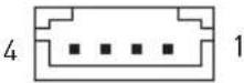 | |||
| 1 VDD_5_DUAL 2 BP_I2C_CLK1 | |||
| 3 BP_I2C_DAT1 4 GND | |||
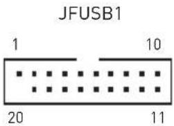 | 1 P5V_AUX_USB_BP0 2 USB3_HEADER_P0_ESD_RX | |||
| 3 | USB3_HEADER_P0_ESD_RXP | 4 | GND | |
| 5 | USB3_HEADER_P0_ESD_TXN | 6 | USB3_HEADER_P0_ESD_TXP | |
| 7 | GND | 8 | USB2_P0_ESD_DN | |
| 9 | USB2_P0_ESD_DP 10 | NA | ||
| 11 USB2_P1_ESD_DP 12 USB2_P1_ESD_DN | ||||
| 13 | GND | 14 | USB3_HEADER_P1_ESD_TXP | |
| 15 | USB3_HEADER_P1_ESD_TXN | 16 | GND | |
| 17 | USB3_HEADER_P1_ESD_RXP | 18 | USB3_HEADER_P1_ESD_RXN | |
| 19 P5V_AUX_USB_BP5 20 | NA | |||
JTPM1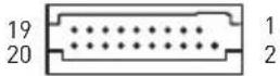 | 1 | N/A | 2 | P0_XLTR_LS_SPI_CS_L |
| 3 P0_RSMRST_LS_L 4 NA | ||||
| 5 | GND | 6 VDD_33_DUAL | ||
| 7 P0_XLTR_LS_SPI_CLK 8 P0_ROM_SPI_WP_L | ||||
| 9 P0_ROM_SPI_HOLD_L 10 P0_XLTR_LS_SPI_MISO | ||||
| 11 NA 12 P0_XLTR_LS_SPI_MOSI | ||||
| 13 SPI_TPM_CS_LS_L 14 GND | ||||
| 15 VDD_33_DUAL 16 NA | ||||
| 17 | IRQ_TPM_SPI_LS_N | 18 | VDD_33_DUAL | |
| 19 P0_RESET_LS_L 20 | VDD_33_DUAL | |||
Motherboard Jumper
| Jumper Name | Default Setting Description | |
| RTC_CLR2_1 | 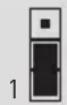 | 1-2: BMC Control2-3: Bypass BMC Control (default) |
Getting Started

All information is subject to change without prior notice.
Necessary Tools

natural_image
Line drawings of four different types of hand tools: screwdriver, pliers, pliers, and gloves (no text or labels)Screwdriver Pliers Tweezers Anti-Static Gloves
Safety Precautions
The following precautions should be observed while handling the system:
- Place the system on a flat and stable surface.
- Do not place the system in environments subject to mist, smoke, vibration, excessive dust, salty or greasy air, or other corrosive gases and fumes.
- Do not drop or jolt the system.
- Do not use another power adapter other than the one enclosed with the system.
- Disconnect the power cord before performing any installation procedures on the system.
• Do not perform any maintenance with wet hands.
- Prevent foreign substances, such as water, other liquids or chemicals, from entering the system while performing installation procedures on the system.
- Use a grounded wrist strap before handling system components such as CPU, Memory, HDD, expansion cards, etc.
- Place system components on a grounded antistatic pad or on the bed that came with the components whenever the components are separated from the system.

The system photos are provided for demonstration of system assembly only. The internal view of your system may vary depending on the model you purchased.
System Setup

Before removing or installing any components, make sure the system is not turned on or connected to the power.
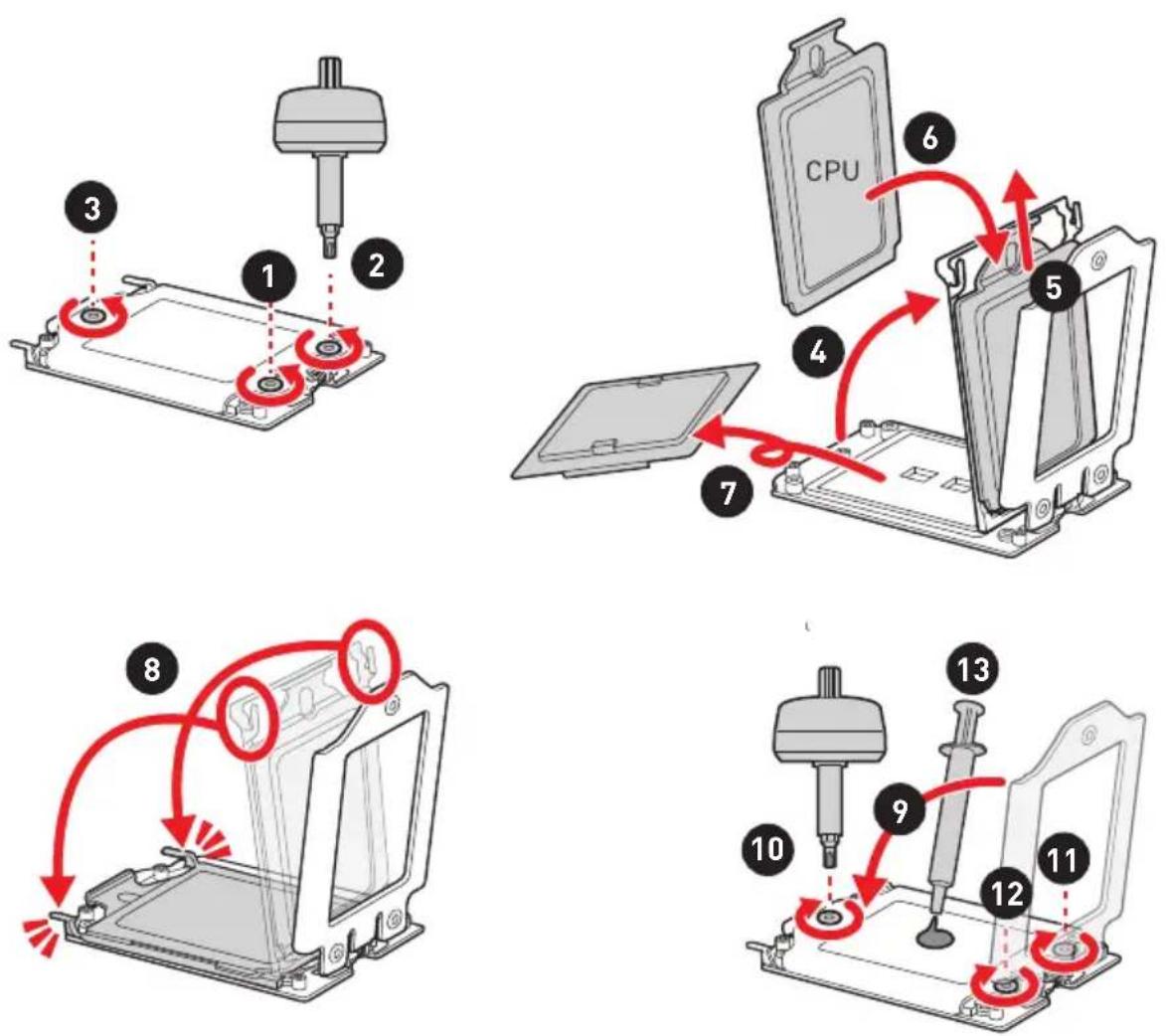
CPU
When installing the CPU, make sure that you install cooler to prevent overheating. If you do not have the CPU cooler, consult your dealer before turning on the computer.
For the instruction of installing CPU cooler, please see Air Cooler Module (Optional) or Water Cooler Module (Optional) chapter.
Important
While replacing the CPU, always turn off the power supply or unplug the power supply's power cord from the grounded outlet first to ensure the safety of CPU.
Overheating will seriously damage the CPU and system. Always make sure the cooling fan can work properly to protect the CPU from overheating. Make sure to apply an even layer of thermal paste (or thermal tape) between the CPU and the heatsink to enhance heat dissipation.
Confirm if your CPU cooler is firmly installed before turning on your system.
Do not touch the CPU socket pins to avoid damage.
Whenever CPU is not installed, always protect your CPU socket pins with the plastic cap covered.
Please refer to the documentation in the CPU cooler package for more details about the CPU cooler installation.
Read the CPU status in BIOS.
Memory
- Unlock the DIMM slot by flipping open its side clips.
- Vertically insert the DIMM into the DIMM slot. The DIMM has an off-center notch at the bottom that will only allow it to fit one way into the DIMM slot.
- Push the DIMM deeply into the DIMM slot. The side clips of the slot will automatically close when the DIMM is properly seated and an audible click should be heard.
- Manually check if the DIMM has been locked in place by the DIMM slot's side clips.
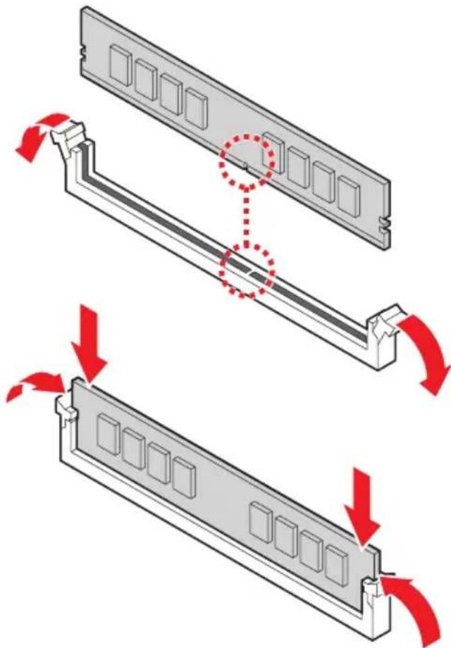
natural_image
Diagram showing two views of a computer RAM module with red arrows indicating motion, no text or symbols present.
You can barely see the golden finger if the memory module is properly inserted in the DIMM slot.
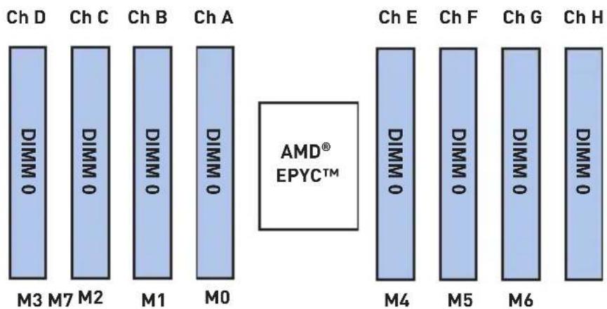
Supported Memory Population
| ChannelNumberof DIMM | Chan D | Chan C | Chan B | Chan A | CPU | Chan E | Chan F | Chan G | Chan H |
| M3 M2 | M1 M0 | M4 M5 | M6 M7 | ||||||
| 1 | Not Recommended Not Recommended | ||||||||
| 2 | |||||||||
| 3 | |||||||||
| 4 V V V V | |||||||||
| 5 Not Recommended Not Recommended | |||||||||
| 6 V V V V V V | |||||||||
| 7 Not Recommended Not Recommended | |||||||||
| 8 V V V V V V V V | |||||||||

Configuration with 8 DIMMs is most recommended.
4 DIMMs configuration is conditionally recommended only if 8 channels cannot be populated, and only with processors that have 128MB L3 or less.
6 DIMMs configuration is conditionally recommended only if 8 channels cannot be populated, and only with <= 256GB per channel, all channels with equal capacity.
M.2 Key M (Optional)


Demonstration
Watch the video to learn how to Install M.2 SSD.
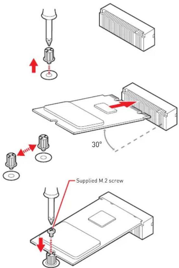
- Loosen the M.2 riser screw from the motherboard.
- Move and fasten the M.2 riser screw to the appropriate location according your M.2 SSD size.
- Insert your M.2 SSD into the M.2 slot at a 30-degree angle.
- Secure the M.2 SSD in place with the supplied M.2 screw.
Hard Disk Drive (Optional)
- Locate the HDD bracket in the system and remove the screws fixing it. Release the HDD bracket from the system for installation.
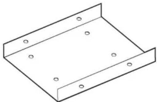
natural_image
Isometric line drawing of a metal bracket with mounting holes (no text or symbols)- Fit the HDD into the bracket with screw holes aligned. Fasten the screws to secure the HDD to the bracket.
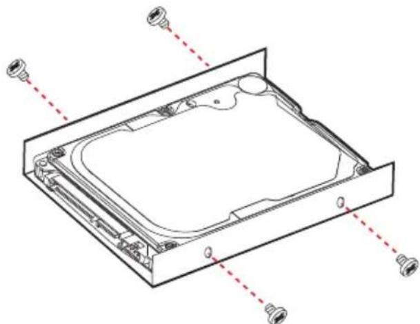
natural_image
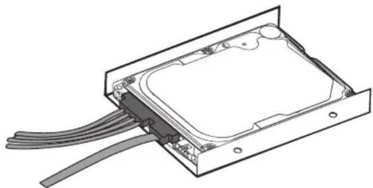
Technical line drawing of a computer chassis with mounting holes and internal components (no text or symbols)- Connect the HDD cable to the HDD. Secure the HDD cable to the bracket if the cable comes with screws and screw holes.
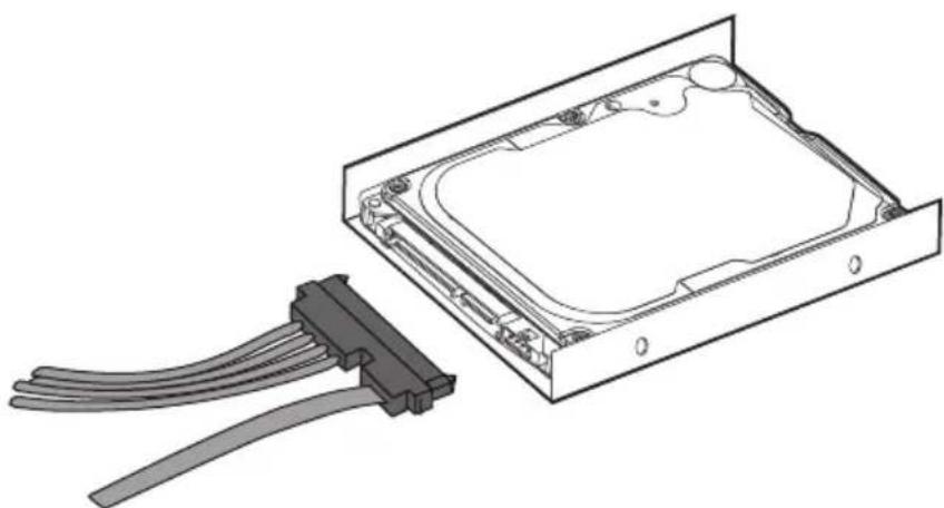
natural_image
Technical line drawing of an internal hard drive with a connector bracket (no text or symbols)- Connect the HDD signal cable to the motherboard.
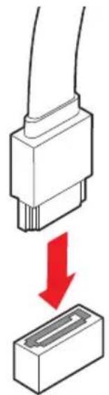
natural_image
Diagram showing a connector being inserted into a rectangular block, with a red arrow indicating the process (no text or symbols present)- Place and secure the HDD set back to the system.
natural_image
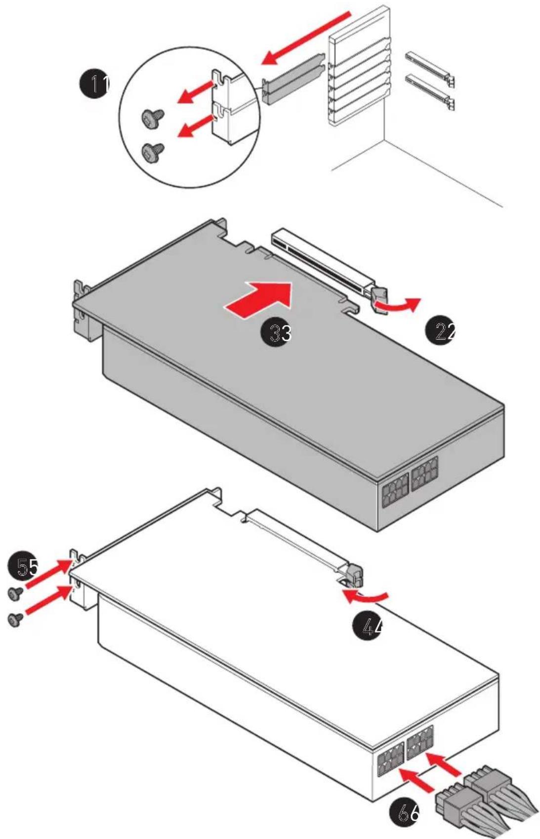
Technical line drawing of an electronic device showing internal components and cable routing (no text or symbols)Graphics Card (Optional)

Reference image only. Appearance will vary.
Air Cooler Module (Optional)

All information and images are subject to change without prior notice.
- Remove the screws from the system cover.
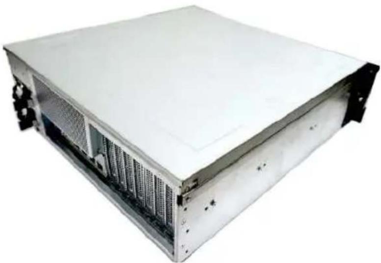
natural_image
Exterior view of a server rack unit with visible drive bays and ventilation slots (no text or labels)- Lift the system cover upward and remove it from the chassis.
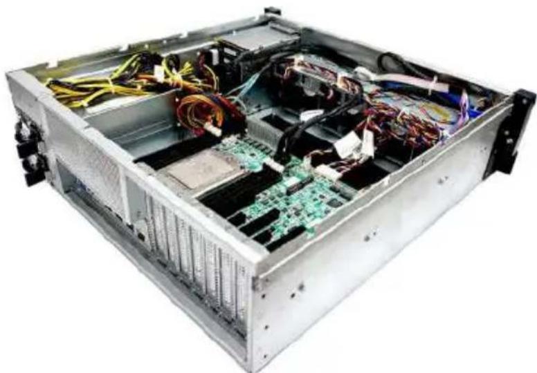
natural_image
Interior view of a server rack with exposed circuit board and wiring (no text or symbols visible)- Check the bottom of the cooler to make sure a thermal interface material is available to help transfer heat.
natural_image
Interior view of a computer motherboard with CPU socket, RAM slots, and wiring (no visible text or symbols)- Check the air flow direction and place the air cooler module atop the CPU with air flow directed toward the I/O side.
natural_image
Interior view of a computer motherboard with CPU socket, RAM slots, and power lines (no visible text or symbols)- Fasten the air cooler module with a T20 screwdriver. It is recommended to tighten the screws in a diagonal sequence.
- Connect the cooler cable to the fan power connector on the motherboard.
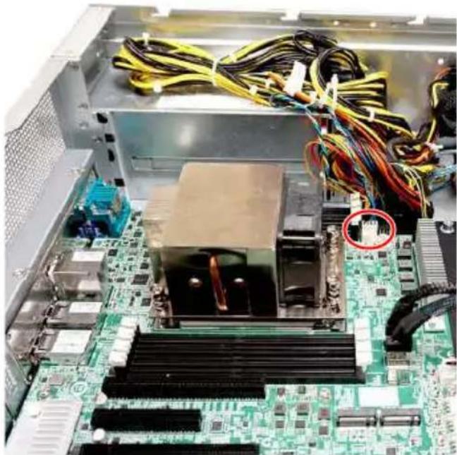
natural_image
Interior view of a computer motherboard with visible CPU socket, RAM slots, and wiring (no text or symbols)- Place the system cover back to the chassis and fasten the screws.

natural_image
Exterior view of a white server rack unit with ventilation grilles and drive bays (no visible text or labels)Follow the above procedures in reverse order to install air cooler module.
Water Cooler Module (Optional)

All information and images are subject to change without prior notice.
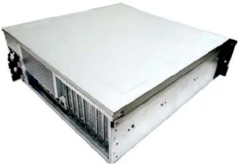
- Remove the screws from the system cover.

natural_image
Exterior view of a server rack unit with visible drive bays and ventilation slots (no text or symbols)- Lift the system cover upward and remove it from the chassis.
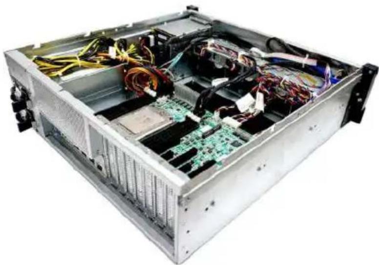
natural_image
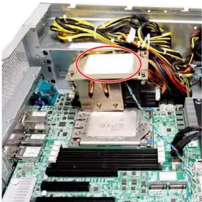
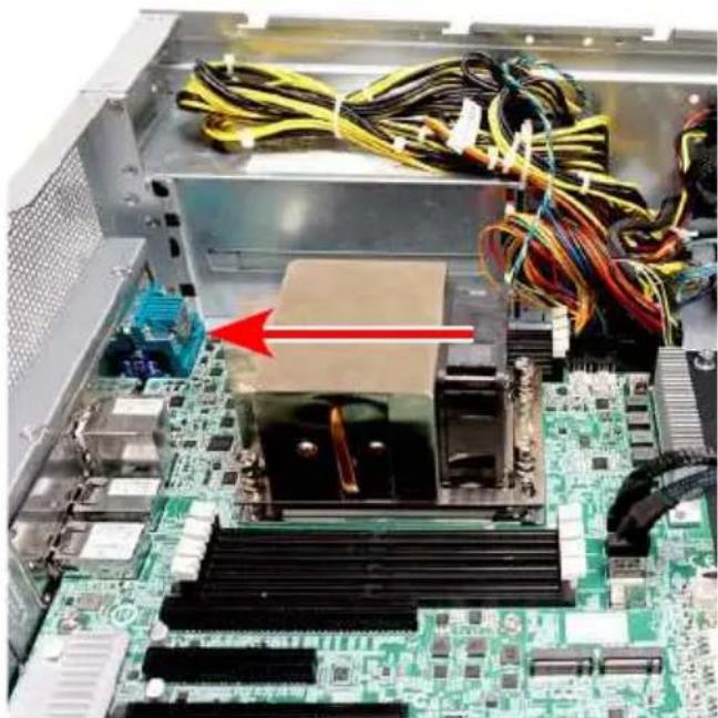
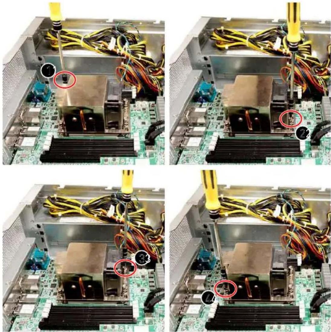
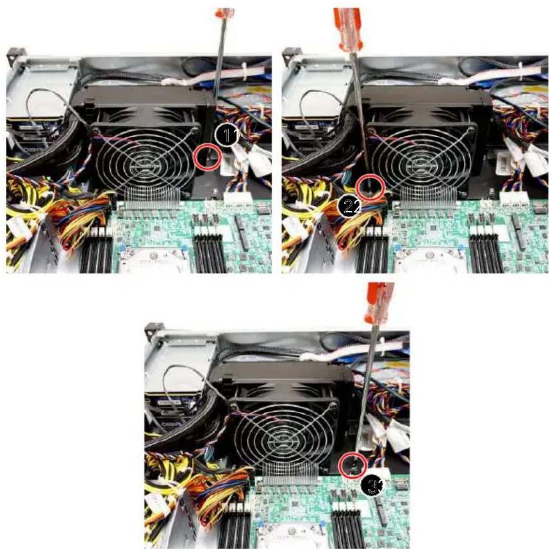
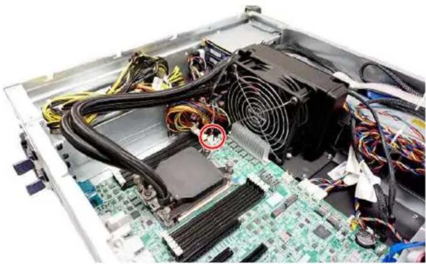
Interior view of a server rack with exposed circuit board and cable, no visible text or labels- Locate the spot where the water cooler module will be installed. Put the cables aside and remove the three screws indicated in the picture.
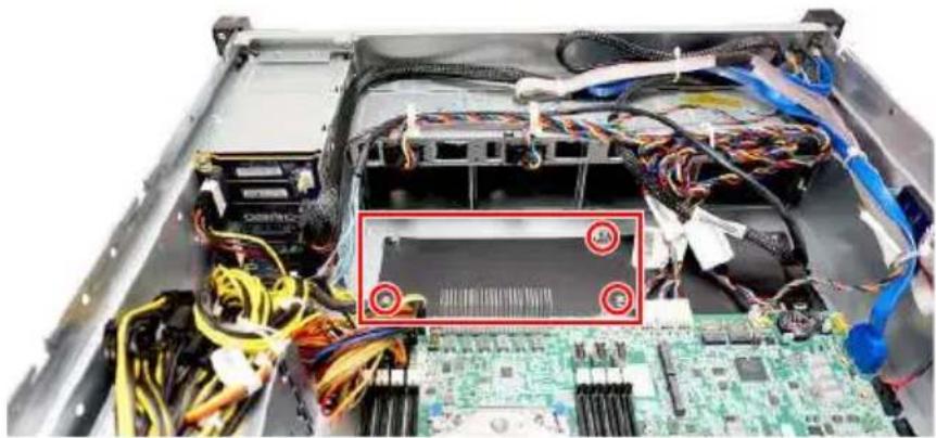
natural_image
Interior view of a server rack with exposed circuit board and cable, no visible text or symbols- Gently put down the radiator with screw holes aligned.
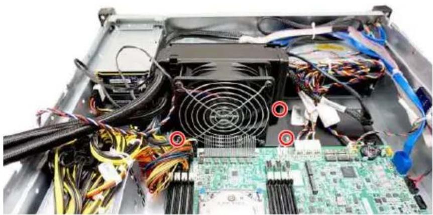
natural_image
Interior view of a computer tower with visible CPU socket, power lines, and circuit board (no text or symbols)- It is recommended to tighten the screws in a diagonal sequence.
- To install the cold plate module onto the CPU, first check the water cooler module package for the following parts.
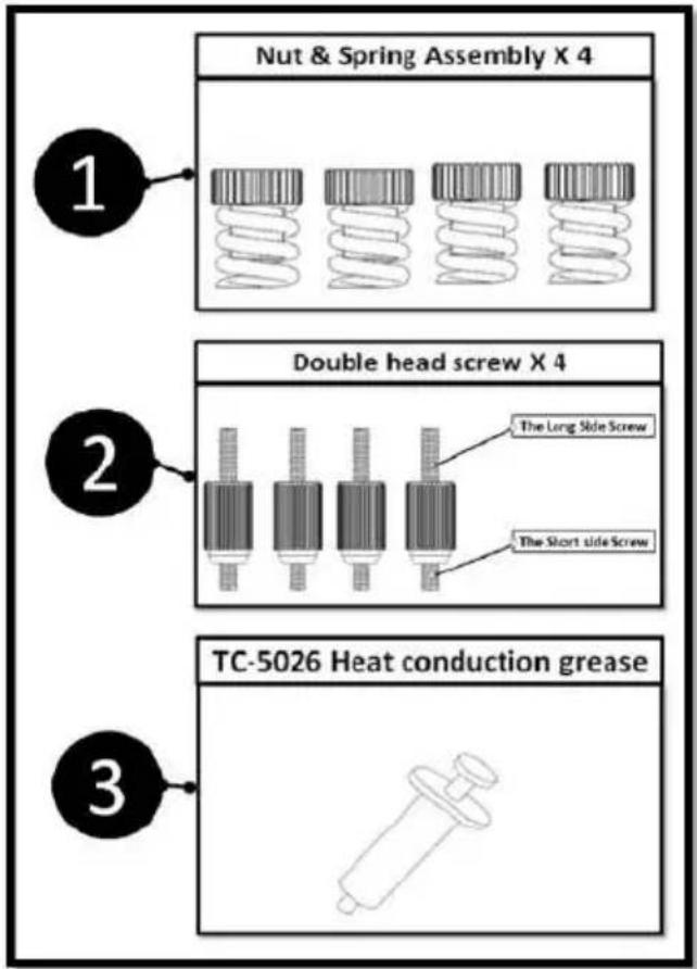
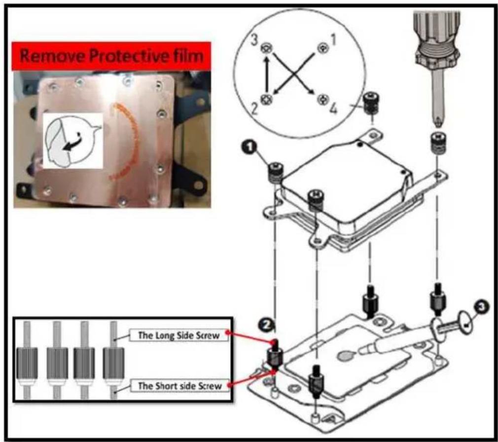
- Fasten the double-head screws to the CPU socket and apply proper amount of heat conduction grease onto the CPU.
- Remove the protective film from the cold plate and place the cold plate onto the CPU.
- Secure the cold plate with the nut & spring assemblies.
natural_image
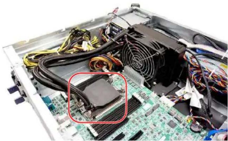
Interior view of a computer motherboard with CPU socket and power supply (no visible text or labels)- Connect the pump and fan power cables to the motherboard.
natural_image
Interior view of a computer motherboard with CPU socket, power supply, and cable (no visible text or labels)- Place the system cover back to the chassis and fasten the screws.
natural_image
Exterior view of a server rack unit with visible drive bays and ventilation grilles (no text or labels)
MSI.COM

EPS.MSI.COM
- Revision
- Regulatory Notices
- WEEE Statement
- Chemical Substances Information
- CE Conformity
- FCC-A Radio Frequency Interference Statement
- Notice 1
- Notice 2
- Battery Information
- European Union:
- BSMI:
- 廢電池請回收
- California, USA:
- Copyright and Trademarks Notice
- Technical Support
- Safety Information
- System Overview
- System Specifications
- Motherboard Connector
- Motherboard Jumper
- Getting Started
- Necessary Tools
- Safety Precautions
- System Setup
- CPU
- Important
- Memory
- Supported Memory Population
- M.2 Key M (Optional)
- Demonstration
- Hard Disk Drive (Optional)
- Graphics Card (Optional)
- Air Cooler Module (Optional)
- Water Cooler Module (Optional)
Brand : MSI
Model : G3101
Category : Server