
CAT4K-70 - Audio/video converter DVDO - Free user manual and instructions
Find the device manual for free CAT4K-70 DVDO in PDF.

| Product Type | Audio/Video Converter |
| Brand | DVDO |
| Model | CAT4K-70 |
| Input Interface | HDMI 2.0 |
| Output Interface | HDMI 2.0 |
| Supported Resolutions | Up to 4K@60Hz |
| Video Support | HDR10, Dolby Vision |
| Audio Support | LPCM 7.1, Dolby Digital, DTS |
| Color Depth | 8/10/12 bit |
| HDCP | 2.2 |
| Power Supply | DC 5V 1A (via USB or adapter) |
| Power Consumption | <5W |
| Dimensions (WxDxH) | 200 x 120 x 30 mm |
| Weight | 0.5 kg |
| Operating Temperature | 0°C to 45°C |
| Storage Temperature | -20°C to 60°C |
| Material | Aluminum alloy |
| LED Indicators | Power, Signal |
| Warranty | 1 year |
| Included Accessories | HDMI cable, USB power cable, manual |
| Maintenance | Clean with dry cloth |
| Safety | Overcurrent protection |
| Repairability | Not user-repairable, contact support |
Frequently Asked Questions - CAT4K-70 DVDO
User questions about CAT4K-70 DVDO
0 question about this device. Answer the ones you know or ask your own.
Ask a new question about this device
Download the instructions for your Audio/video converter in PDF format for free! Find your manual CAT4K-70 - DVDO and take your electronic device back in hand. On this page are published all the documents necessary for the use of your device. CAT4K-70 by DVDO.
USER MANUAL CAT4K-70 DVDO
For optimum performance and safety, please read these instructions carefully before connecting, operating or adjusting this product. Please keep this manual for future reference.
Surge protection device recommended
This product contains sensitive electrical components that may be damaged by electrical spikes, surges, electric shock, lighting strikes, etc. Use of surge protection systems is highly recommended in order to protect and extend the life of your equipment.
Caution
The product requires the use of UTP connectors. Please connect in direct interconnection method and do not cross connect.

Direct Interconnection Method
Table of Contents
- Introduction....1
- Features. 1
- Package Contents....2
- Specifications....2
- Operation Controls and Functions....4
5.1 Transmitter Panel....4
5.2 Receiver Panel. 5
5.3 IR Pin Definition ....7 - Application Example....8
1. Introduction
This 18Gbps HDMI Extender can extend HDMI HD signal and IR control signal to a distance up to 230ft / 70m via a single CAT6/6a cable, which can achieve zero-delay, uncompressed long-distance transmission between the transmitter and receiver. Video resolution is up to 4K2K@60Hz. It supports EDID copy pass-through function between the source device and display device. It supports POC function.
This Extender can be widely used in multi-media conference halls, TV teaching and large screen displays.
2. Features
☆ HDMI2.0b and HDCP 2.2 compliant
☆ Support 18Gbps video bandwidth
☆ Support video resolution up to 4K2K@60Hz RGB/YCBCR 4:4:4
☆ The transmission distance can be extended up to 230ft / 70m via a single CAT6/6a cable
☆ Support HDR, HDR10, HDR10+, Dolby Vision, HLG
☆ Support bi-directional IR control signal pass-through
☆ Audio formats: LPCM 7.1, Dolby True HD, DTS HD Master
☆ EDID copy pass-through function between the source device and display device
☆ Support ARC and audio de-embedding, audio is output through the optical fiber port of the receiver
☆ Support bi-directional POC (Power over Cable) function
☆ Compact design for easy and flexible installation
3. Package Contents
① 1 x 18Gbps HDMI Extender (Transmitter)
② 1 x 18Gbps HDMI Extender (Receiver)
③ 1 x IR Blaster cable (1.5 meters)
④ 1 x IR Wideband Receiver cable (1.5 meters)
⑤ 4 x Mounting Ears
⑥ 8 x Machine Screws (KM3*4)
⑦ 1 x 12V/1A Locking Power Adapter
⑧ 1x User Manual
4. Specifications
| Technical | |
| HDMI Compliance | HDMI 2.0b |
| HDCP Compliance | HDCP 2.2 |
| Video Bandwidth | 18Gbps |
| Video Resolution | Up to 4K2K@60Hz RGB/YCBCR 4:4:4 |
| IR Level | 5Vp-p |
| IR Frequency | Wideband 20K-60KHz |
| Transmission Distance | 4K2K@60Hz 4:4:4--70m, 1080P--70m (CAT6/6a cable) |
| Color Space | RGB 4:4:4, YCbCr 4:4:4, YCbCr 4:2:2, YCbCr 4:2:0 |
| Color Depth | 8/10/12bit |
| HDR | HDR, HDR10, HDR10+, Dolby Vision, HLG |
| Audio Formats | HDMI: LPCM 7.1CH, Dolby True HD, DTS-HD MasterOptical: Dolby 5.1, DTS 5.1, PCM 2.0 |
| Connection | |
| Transmitter | Input: 1×HDMI IN [Type A, 19-pin female]Output: 1×HDMI OUT [RJ45]1×CAT OUT [RJ45]Control: 1×SERVICE [Micro-USB jack]1×IR IN [3.5mm Stereo Mini-jack]1×IR OUT [3.5mm Stereo Mini-jack] |
| Receiver | Input: 1×CAT IN [RJ45]Output: 1×HDMI OUT [Type A, 19-pin female]1×TOSLINKControl: 1×SERVICE [Micro-USB jack]1×IR IN [3.5mm Stereo Mini-jack]1×IR OUT [3.5mm Stereo Mini-jack] |
| Mechanical | |
| Housing | Metal Enclosure |
| Color | Black |
| Dimensions | Transmitter / Receiver: 90mm (W)×68mm (D)×18mm (H) |
| Weight | Transmitter: 160g, Receiver: 155g |
| Power Supply | DC 12V/1A;Support bi-directional POC function |
| Power Consumption | 3.36 W (max) |
| Operating Temperature | 0°C ~ 40°C / 32°F ~ 104°F |
| Storage Temperature | -20°C ~ 60°C / -4°F ~ 140°F |
| Relative Humidity | 20~90% RH (non-condensing) |
5. Operation Controls and Functions
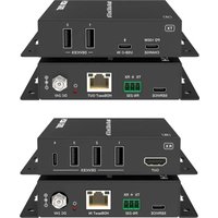
5.1 Transmitter Panel


| No. | Name | Function Description |
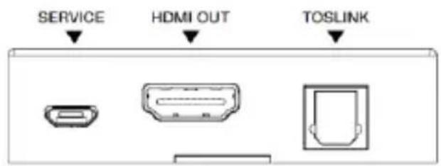
| 1 | SERVICE | Firmware update port. |
| 2 | HDMI OUT | HDMI signal loop output port. Connect to HDMI display devices with HDMI cable. |
| 3 | HDMI IN | HDMI signal input port. Connect to HDMI source device with HDMI cable. |
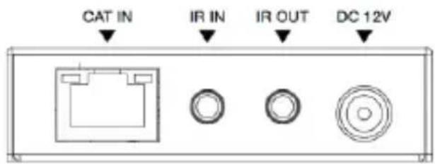
| 4 | CAT OUT | RJ45 connector for connecting the CAT IN port of the Receiver with CAT6/6a cable. |
| 5 | Link Signal Indicator (Green) | Illuminating: Transmitter and Receiver are in good connection status.Flashing: Transmitter and Receiver are in poor connection status.Dark: Transmitter and Receiver are not connected. |
| 6 | Data Signal Indicator (Orange) | Illuminating: HDMI signal with HDCP.Flashing: HDMI signal without HDCP.Dark: No HDMI signal. |
| 7 | IR IN | Connect to IR receiver cable, the IR receive signal will emit to the IR OUT port of the Receiver. |
| 8 | IR OUT | Connect to IR blaster cable, the IR emit signal is from the IR IN port of the Receiver. |
| 9 | DC 12V | DC 12V/1A power input port.Note that the extender supports POC function, it means that either Transmitter or Receiver is connected to 12V/1A power supply, the other doesn’t need power supply. |
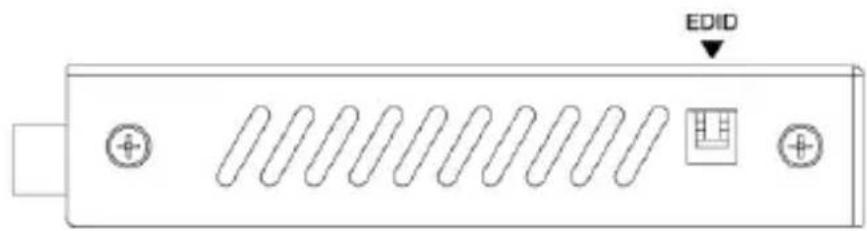
| 10 | EDID DIP switch | Use the DIP switch to set EDID. (Switching to the upper end indicates 1; switching to the lower end indicates 0.)11 - EDID information is copied from the display at the RX.10 - EDID is preset to 4K@60Hz Stereo01 - EDID is preset to 1080p Stereo00 - EDID information is copied from the HDMI OUT at the TX. |
5.2 Receiver Panel
| No. | Name | Function Description |
| 1 | SERVICE | Firmware update port. |
| 2 | HDMI OUT | HDMI signal output port. Connect to HDMI display devices with HDMI cable. |
| 3 | TOSLINK | Optical fiber audio output port. Connect to amplifier with optical cable. |
| 4 | CAT IN | RJ45 connector for connecting the CAT OUT port of the Transmitter with CAT6/6a cable. |
| 5 | Link Signal Indicator (Green) | Illuminating: Transmitter and Receiver are in good connection status.Flashing: Transmitter and Receiver are in poor connection status.Dark: Transmitter and Receiver are not connected. |
| 6 | Data Signal Indicator (Orange) | Illuminating: HDMI signal with HDCP.Flashing: HDMI signal without HDCP.Dark: No HDMI signal. |
| 7 | IR IN | Connect to the IR receiver cable. The IR signal will send to the IR OUT port of the Transmitter. |
| 8 | IR OUT | Connect to the IR blaster cable, the IR signal is from IR IN port of the Transmitter. |
| 9 | DC 12V | DC 12V/1A power input port.Note that the extender supports POC function, it means that either Transmitter or Receiver is connected to 12V/1A power supply, the othe doesn't need power supply. |
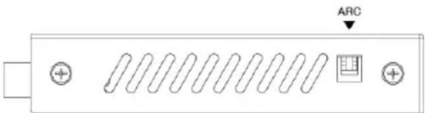
| 10 | ARC DIP switch | Use the DIP switch to control ARC function. (Switching to the upper end indicates 1; switching to the lower end indicates 0. Note that only the left switch is valid, the right switch is invalid.)1X - Disable the ARC function0X - Enable the ARC function |
Note:
When the ARC function is enabled, the audio returned from the ARC supported TV connected to the Receiver will be output through the TOSLINK port (not the HDMI IN port or HDMI OUT port of the Transmitter);
When the ARC function is disabled, the audio extracted from the HDMI IN port of the Transmitter will be output through the TOSLINK port.
5.3 IR Pin Definition
IR Receiver and Blaster pin's definition is as below:

Note:
When the angle between the IR receiver and the remote control is ± 45^ , the transmission distance is 0-5 meters;
When the angle between the IR receiver and the remote control is ± 90^ , the transmission distance is 0-8 meters.
6. Application Example

flowchart
graph TD
    A["Service"] --> B["HDMI OUT"]
    B --> C["HDMI IN"]
    C --> D["Transmitter"]
    D --> E["CAT 6/6a"]
    E --> F["IR IN"]
    E --> G["IR OUT"]
    E --> H["DC 12V"]
    I["UHDTV"] --> J["DVD or Blu-ray Player"]
    K["Service"] --> L["HDMI OUT"]
    L --> M["TOSLINK"]
    N["Receiver"] --> O["Audio Amplifier"]
    P["IR Receiver"] --> Q["IR Blaster"]
    R["Power Supply"] --> S["IR Blaster"]

HIGH-DEFINITION MULTIMEDIA INTERFACE
The terms HDMI and HDMI High-Definition Multimedia interface, and the HDMI Logo are trademarks or registered trademarks of HDMI Licensing LLC in the United States and other countries.
DVDO
Follow us


Brand : DVDO
Model : CAT4K-70
Category : Audio/video converter