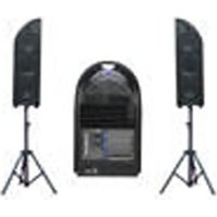
OEX900 - Loudspeaker ALTO - Free user manual and instructions
Find the device manual for free OEX900 ALTO in PDF.


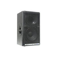
| Product Type | Portable PA System with Trolley, 3-Way Speaker System (2 satellites + subwoofer + mixer) |
| Mixer | 8-channel, 24-bit DSP effects, 256 presets (16 presets x 16 variations) |
| Microphone Inputs | 6 XLR with +48V phantom power, ultra low noise preamps |
| Line Inputs | 2 stereo (1/4" TRS), 2 stereo channels with XLR mic combo |
| Equalizer | 3-band per channel (HI 12kHz, MID 2.5kHz, LOW 80Hz), ±15dB; plus 7-band graphic EQ for Main and Monitor |
| Amplifier Power | Satellites: 150W x 2 RMS (Class AB); Subwoofer: 250W RMS (Class H); Total peak: 1200W |
| Frequency Response | 45Hz – 20kHz (-10dB) |
| Maximum SPL | 119.5dB continuous, 122.5dB peak (calculated at 1m) |
| Speaker Drivers | Low: 15" (385mm) with 2.5" voice coil; Mid: 2 x 6.5" (165mm) with 1.5" coil; High: 1" compression driver with 1" coil; Horn coverage 80°H x 80°V |
| Dimensions (WxDxH) | 1060 x 700 x 700 mm |
| Net Weight | 43.04 kg |
| Gross Weight | 60.04 kg |
| Power Supply | AC mains via IEC power cord (voltage rating as per manual) |
| Accessories Included | 2 F8 folding speaker stands, 2 x 7m speaker cables, 1 x 2m signal cable, 1 power cord |
| Cabinet Material | Plastic reinforced (polypropylene) |
| Cleaning | Use dry cloth; do not use solvents like benzol or alcohol |
| Safety | Protective ground, proper AC voltage, keep away from moisture/heat, do not remove covers |
| Fuse | Use recommended type per manual; do not short-circuit holder |
| Warranty | 1 year from purchase date; register within 10 days |
Frequently Asked Questions - OEX900 ALTO
User questions about OEX900 ALTO
0 question about this device. Answer the ones you know or ask your own.
Ask a new question about this device
Download the instructions for your Loudspeaker in PDF format for free! Find your manual OEX900 - ALTO and take your electronic device back in hand. On this page are published all the documents necessary for the use of your device. OEX900 by ALTO.
USER MANUAL OEX900 ALTO
natural_image
Photograph of a portable electronic device setup with two speakers and a central display case, no visible text or symbols.
www.altoproaudio.com
Version 1.3 October 2005
- English -
SAFETY RELATED SYMBOLS


This symbol, wherever used, alerts you to the presence of un-insulated and dangerous voltages within the product enclosure. These are voltages that may be sufficient to constitute the risk of electric shock or death.

This symbol, wherever used, alerts you to important operating and maintenance instructions. Please read.

Protective Ground Terminal

AC mains (Alternating Current)

Hazardous Live Terminal
ON: Denotes the product is turned on.
OFF: Denotes the product is turned off.
WARNING
Describes precautions that should be observed to prevent the possibility of death or injury to the user.
CAUTION
Describes precautions that should be observed to prevent damage to the product.

Disposing of this product should not be placed in municipal waste and should be Separate collection.
WARNING
- Power Supply
Ensure that the mains source voltage (AC outlet) matches the voltage rating of the product. Failure to do so could result in damage to the product and possibly the user.
Unplug the product before electrical storms occur and when unused for long periods of time to reduce the risk of electric shock or fire.
- External Connection
Always use proper ready-made insulated mains cabling (power cord). Failure to do so could result in shock/death or fire. If in doubt, seek advice from a registered electrician.
- Do Not Remove Any Covers
Within the product are areas where high voltages may present. To reduce the risk of electric shock do not remove any covers unless the AC mains power cord is removed.
Covers should be removed by qualified service personnel only.
No user serviceable parts inside.
- Fuse
To prevent fire and damage to the product, use only the recommended fuse type as indicated in this manual. Do not short-circuit the fuse holder. Before replacing the fuse, make sure that the product is OFF and disconnected from the AC outlet.
- Protective Ground
Before turning the product ON, make sure that it is connected to Ground. This is to prevent the risk of electric shock.
Never cut internal or external Ground wires. Likewise, never remove Ground wiring from the Protective Ground Terminal.
- Operating Conditions
Always install in accordance with the manufacturer's instructions.
To avoid the risk of electric shock and damage, do not subject this product to any liquid/rain or moisture. Do not use this product when in close proximity to water.
Do not install this product near any direct heat source.
Do not block areas of ventilation. Failure to do so could result in fire.
Keep product away from naked flames.
IMPORTANT SAFETY INSTRUCTIONS
Read these instructions
Follow all instructions
Keep these instructions. Do not discard.
Heed all warnings.
Only use attachments/accessories specified by the manufacturer.
• Power Cord and Plug
Do not tamper with the power cord or plug. These are designed for your safety.
Do not remove Ground connections!
If the plug does not fit your AC outlet seek advice from a qualified electrician.
Protect the power cord and plug from any physical stress to avoid risk of electric shock.
Do not place heavy objects on the power cord. This could cause electric shock or fire.
- Cleaning
When required, either blow off dust from the product or use a dry cloth.
Do not use any solvents such as Benzol or Alcohol.
For safety, keep product clean and free from dust.
- Servicing
Refer all servicing to qualified service personnel only.
Do not perform any servicing other than those instructions contained within the User's Manual.
TABLE OF CONTENTS
- INTRODUCTION ....3
- FEATURES ....3
- QUICK START ....5
- CONTROL ELEMENTS ....8
- PRESET LIST ...... 12
- OEX900 WIRING GUIDE ......13
- TECHNICAL SPECIFICATIONS ....14
- WARRANTY ....16
1. INTRODUCTION
Congratulations! Now you are the owner of the OEX900. The OEX900 is a plastic reinforced trolley that includes a versatile mixer with DSP effects, L&R full range speaker cabinets and sub-woofer, and some essential accessories such as power cord, signal cables, speaker cables, and speaker stands. The OEX900 adopts an optimal crossover network and advanced power amplifier technologies, which ensures its incredible versatility and excellent audio performances.
The L&R speaker cabinets are tightly hooked on the trolley. When you operate the OEX900, take care of the setting of the L&R cabinets first. It is the development of ALTO's experience and knowledge of speaker technology, in order to create a system which can faithfully reproduce sound for each kind of applications.
The sub-woofer is built in trolley. It contains a 15" low speaker, which delivers a natural and powerful sound and that will bring you unprecedented low frequency emission.
Inlaid in OEX900 panel there's compact extractable 8-channel mixer, which uses 24-bit A/D&D/A converters and 24-bit DSP effects with accurate algorithms (256 presets). It also provides 6 MIC inputs with ultra low noise microphone pre-amplifiers and +48V PHANTOM power at as well as warm, natural 3-band EQ; AUX send/return and 2TK in/out and so on.
In a word, it is ideally suited for live sound applications, small venues applications, recording and other musical purposes. In order to get the best from your OEX900, we recommend you to thoroughly read this owner's manual before installation and operation.

natural_image
Black and white photo of a futuristic helmet with winged design (no text or symbols visible)2. FEATURES
- Trolley appearance
- 2(two-way satellites) + 1(subwoofer) + 1 (8-channel mixer super combination)
- Three-way full-range speaker system with 15" subwoofer
- 6 XLR MIC input with ultra low noise microphone pre-amplifiers and +48VPHANTOM power
- 2 stereo LINE input
- Warm, natural 3-band EQ for each channel
- Precision level control
• 24-bit DSP effects with powerful algorithms (16 presets with 16 variations each) - Extremely high headroom offering excellent dynamic range
- Plastic reinforced cabinet (polypropylene)
- High power output with 150W*2 (L&R speaker) / 150W*2 (subwoofer)
- Two 7 m speaker cables
- Two F8 folding speaker stands
- Compartment for storing F8 folding stands, speaker cables, signal cable and power cord etc.
Accessory List:
Folding speaker stands 2 F8 ✗
Power cord 1 IEC power cord ✗
Signal cable 1 2m ×
Customized Speaker Cable 2 7m ✗

natural_image
Interior view of a mechanical component with multiple cylindrical pins inserted (no visible text or symbols)In following picture you see OEX900 most important components.
High quality L&R full range speaker cabinets
Powerful sub-woofer
Versatile multi-channel mixer

natural_image
Photograph of a portable electronic device setup with two speakers and a central display case, no visible text or symbols.3. QUICK START
Though the OEX900 looks like a super formidable giant, you don't have to worry about how to carry it. As the OEX900 is equipped with two wheels, you can think of it as a trolley. Seeing is believing. Operating this unit, you will find that it is really versatile and user-friendly. Following steps will give you a guide line to set up your OEX900.
Note: Make all initial connections with the system powered off, and, in order to avoid damaging your speakers and excessive noise, with main mix volume control of the mixer completely turned down.
- First of all extract the F8 folding speaker stands from their compartment, as shown in Fig.1. Then, as shown in Fig.2, unhook, the L&R speaker cabinets from the trolley in the right direction, unsuitable operation may damage your equipment. In order to prevent equipment damage, please place the speaker stands on a solid, even surface.

natural_image
Person inserting a small object into a dark container (no visible text or symbols)
natural_image
Close-up of a hand pressing down on a dark mechanical component with three circular components (no visible text or symbols)Fig.1 Fig.2
• Fix the L&R speaker cabinets on stands. as shown in Fig.3.
Note: In order to avoid feedback, please position the speakers facing the audience and far away from the microphone.

natural_image
Five different types of lighting equipment with transparent stands and a central display case, arranged in two rows (no text or symbols visible)Fig.3
Fig.4
- Then, position the sub-woofer(trolley). Please be careful about this step, as shown in above Fig.4 proper position will allow the sub-woofer to develop his full power and sound character.
- Depending on application requirements, you can disassemble or not the mixer from the trolley. For this application 2m. signal cable is available, as shown in following Fig.5.

natural_image
Exterior view of a black plastic battery casing (no visible text or symbols)
natural_image
3D rendered mechanical component with no visible text or symbolsFig.5
• After that, set up the system.
Note: During this step too the system must be powered off, and, in order to avoid damaging your speakers and/or to produce noise the mixer main volume control should be competently turned off.
Connect one side of the speaker cable to the left/right power outputs (speakon connectors) of system, and the other side to the left/right speaker cabinets (speakon connectors), as shown in Fig.6.
Warning! Do not connect additional speakers to the powered output. The supplied system speakers provide a perfect load for the built-in amplifier.

natural_image
Close-up of a metallic electrical panel with two circular buttons and a black cable (no visible text or symbols)
natural_image
Close-up of a metallic electrical plug inserted into a circular socket (no text or symbols visible)Fig.6
Make sure that the mixer has been connected to the system by using the appropriate connector and the customized cable, as shown in Fig.7.

natural_image
Interior view of a computer room showing a white monitor with cable and a black-outboard (no visible text or symbols)Fig.7
Connect Microphone, CD, Tape or MD player (Line sources) etc. to the appropriate MIC/LINE mixer input connectors (XLRor1/4"TRS jacks), as shown in Fig.8.

natural_image
Close-up of a gloved hand using a power tool to adjust or install electronic equipment (no visible text or symbols)
natural_image
Close-up of a hand using wires to connect electronic components on a control panel (no visible text or symbols)Fig.8
• Now you can turn on the power switch.
- Turn up the volume control, use the PFL function to get the proper input level for each mixer channel, then adjust the main mix level control to manage the output level.
- At the end of your session, put all your levels to zero, turn off your system, then collect all the cables and put them back in their places all accessories into assigned storage compartment. Finally, lay the speakers face down on top of trolley and secure the six latches. Now the OEX900 is ready to be carried everywhere.

Fig.9
4.CONTROL ELEMENTS

(1). MIC IN
These electronically balanced XLR sockets have been designed to accept microphone signals, providing low noise microphone pre-amplifier, as well as phantom power for condenser microphone by pressing the PHANTOM power switch.
Note: You shall never connect an unbalanced microphone to the XLR socket if you don't want to damage both the microphone and mixer.
(2). LINE IN
These balanced 1/4"TRS jacks have been designed to accept line level inputs such as keyboards outputs, CD, players, MD/tape outputs, etc...
(3). Stereo Input
This channel is equipped with two 1/4" TRS jacks for stereo input. Connecting the left input jack only, the input will operate in mono mode. Furthermore, it also provides the XLR connector for MIC input. The OEX900 is provided with two stereo channels.
(4). 20dB PAD
Pressing this button the input signal will be attenuated by 20dB. In such way you'll obtain increased headroom and you'll reduce the risk of distortion due to input level peaks with too high input signal.
(5). Equalizer
Each channel is equipped with 3-band warm, natural EQ: HI, MID and LOW bands will allows you to shape the sound of program material in a very efficient way.
HI
Treble control. You can use it to get rid of high frequency noises or to boost the sound of cymbals and human voice higher harmonics. The gain range can be varied from -15dB to +15dB with a center frequency of 12kHz. MID
Midrange control. It can affect most fundamental frequencies of all musical instruments and human voice. A careful use of this control will give you a very wide panorama of sound effects. The gain range can be varied from -15dB to +15dB with a center frequency of 2.5kHz.
LOW
Bass control. It can boost male voice or kick-drum and bass guitar. Your system will seem much bigger than it really is. The gain range can be varied from -15dB to +15dB with a center frequency of 80Hz.
(6). AUX Sends
Both these controls are used to adjust the level of signal sent to AUX buses. These sends controls are adjustable in - to +15dB. The MON (AUX1) control is configured PRE-FADER, it means that its signal is independent by channel fader setting. It is suited to be used as monitor mix in a live sound mixing, or for a headphone mix in recording application. The(AUX2) control is configured as POST-FADER, it means that the audio signal will be affected by channel fader settings. This signal is assigned to onboard DSP(digital effects module). Via AUX2 OUT connector the AUX2 signal can be sent to an external effect device.
(7). PAN/BAL Control
The pot controls the channel's position between left and right in the stereo bus. Of course you can use it to "move" the channel signal in stereo front to create spatial effects as well as.
(8). LEVEL Control
This pot provides smooth control over levels.
(9). OPERATING LED Display
The LED indicates when OEX900 power is switched ON.
(10). Graphic EQ
OEX900 is provided with two graphic EQs, one for MAIN MIX, the other for MONITOR MIX. These graphic EQ have 7-band fader controls. Via these faders, you can boost or attenuate the selected frequency by 15dB at a preset bandwidth. They are used to modify the frequency "contour" of sound, to adapt it to your musical taste and ambient characteristics. When all faders are at the center position, the equalizer has flat response.
(11). MONITOR LEVEL Control
This control adjusts the level of monitor output by a range of - to +10dB.
(12). MAIN LEVEL Control
By rotating this pot you'll simultaneously adjust the overall volume of the left and right main mix outputs in to +10dB .
(13). PRESETS Control (DSP Section)
Adjust this knob to select the effect you wish to perform. There are 16 options available: several kinds of reverb, mono and stereo delay, modulation effects, and versatile two-effect combinations.
(14). VARIATIONS Control
This control provides 16 variations for each preset, each variation has been designed modifying several parameters. For further details, please refer to chapter 5.
(15). PEAK LED
This LED is lit when the DSP input signal is too strong. This LED is lit when the DSP is muted too.
(16). DSP MUTE Switch
This switch serves to activate/deactivate the built-in effect section. For your convenience you can also use the FOOT SW for this operation.
(17). FOOT SW. Jack
This 1/4" phone jack can be used to connect an external foot-switch to turn on/off the built-in effect module.
(18). AUX/DFX RET
This pot adjusts the internal/external effect from 0 to 10.
(19). AUX2 OUT
This 1/4" phone jack outputs AUX2 bus line signal.
(20). STEREO RTN
This1/4" phone jack is used to return the signal of external unit to the main mix. You can also use it as an extra auxiliary input.
(21). TAPE IN/OUT
These RCA connectors are useful to connect the output/input of a DAT, cassette or taper recorder.
(22). TAPE TO Switch
Pushing this switch to left, TAPE IN signal will be routed to CH7-8 path, so the signal will be controlled by channel level control and main level control. Pushing this switch to right, the TAPE IN signal will be directly routed to main mix bus, and its signal will be affected by main level control only.
(23). 2TK IN Control
This pot adjusts the level of 2TK IN signal in to MAX range.
(24). MAIN OUT
These left and right main mix. You can use these connectors to output the main mixconnectors output signal to external PA system or active speakers.
(25). MONITOR OUT
This1/4" phone jack outputs the signal from MON (AUX1) bus to the input of external monitor amplifier or active monitor speaker.
(26). HEADPHONE OUT
This1/4" stereo phone jack can be used to connect stereo headphones.
(27). PHANTOM Switch
Via this switch, you can turn on/off the +48V phantom power for all microphone pre-amps.
(28). AC INLET with FUSE HOLDER
Standard IEC receptacle, connect your OEX900 to mains with the supplied power cord.
(29). POWER Switch
It switches on/off the OEX900 main power.
(30). Powered Output Connectors
These 4-way speakon type connectors are used to output the powered signal to L&R speaker cabinets. Note: in order to avoid damaging your built-in amplifier, please pay attention to speaker impedance. Lower load impedance is not permitted.

(29) (30)(28)

- PRESET LIST
| No. | Preset | Description | Controllable parameter | |
| Parameter Variable range | ||||
| 1 | VOCAL 1 | Simulate a room with small delay time. | Decay timePre-delay | 0.8~1.1s0~79ms |
| 2 | VOCAL 2 | Simulate a small space with slight decay time. | Decay timePre-delay | 0.8~2.5s0~79ms |
| 3 | LARGE HALL | Simulate a large acoustic space of the sound. | Decay timePre-delay | 3.6~5.4s23~55ms |
| 4 | SMALL HALL | Simulate a small acoustic space of the sound. | Decay timePre-delay | 1.0~2.9s20~45ms |
| 5 | LARGE ROOM | Simulate a studio room with many early reflections. | DecaytimePre-delay | 2.9~4.5s23~55ms |
| 6 | SMALL ROOM | Simulate a bright studio room. | Decay timePre-delay | 0.7~2.1s20~45ms |
| 7 | PLATE | Simulate the transducers sound like classic bright vocal plate. | Decay timePre-delay | 0.6~6.1s10ms |
| 8 | TAPE REVERB | Simulate a record head and multiple playback heads at intervals along the tape. | Decay timePre-delay | 1.3~5.4s0~84ms |
| 9 | SPRING REVERB | Simulate the analog transducers' springs lightly stretched sound. | Decay timePre-delay | 1.3~5.4s0~35ms |
| 10 | MONO DELAY | Reproduce the sound input on the outputafter a lapse of time. | Period | 60~650ms |
| 11 | STEREO DELAY | Recreate the input sound on the stereo output with different time. | PeriodFeedback | 210~400ms37~73% |
| 12 | FLANGER | Simulate to play with another person carryingout sam e the notes on the same instrument | Rate | 0.16~2.79Hz |
| 13 | CHORUS | Recreate the illusion of more than one instrument from a single instrument sound | Rate | 0.5~5Hz |
| 14 | REV.+DELAY | Delay with room effect | Delay periodRev. decay time | 211~375ms1.0~2.9s |
| 15 | REV.+FLANGER | Stereo chorus and large room reverb | Flanger RateRev. decay time | 0.16~2.52Hz1.5~2.9s |
| 16 | REV.+CHORUS | Simulate the sound effect achieved by rotating horn speakers and a bass cylinder | Chorus rateRev. decay time | 0.5~4.74Hz1.5~2.9s |
6. OEX900 WIRING GUIDE
Defective wiring may degrade the performance of OEX900 product so, please, use good quality screened audio cable. Please follow the descriptions below to connect the OEX900 with external equipment, without experiencing any noise or signal loss.
| Model | Input/Output Connector | Type | Description | Diagram |
| Mixer Section | MIC IN | XLR | PIN1 = Screen / GroundPIN2 = Hot SignalPIN3 = Cold Signal | • 1/4" jack TRS Type Balanced TRS Type Balanced TRS Type Unbalanced TRS Type Unbalanced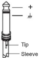 TS Type Unbalanced TS Type Unbalanced |
| LINE IN | 1/4" jack TRS | TIP = HotRING = ColdSLEEVE = Screen | ||
| AUX SEND | 1/4" jack TS | TIP = HotSLEEVE = Screen | ||
| TAPE IN | RCA | TIP = HotSLEEVE = Screen | ||
| TAPE OUT | RCA | TIP = HotSLEEVE = Screen | ||
| MIX OUT | 1/4" jack TRS | TIP = HotRING = ColdSLEEVE = Screen | • RCA Connector | |
| HEADPHONE | 1/4" jack TRS | TIP = HotRING = ColdSLEEVE = Screen | ||
| POWER CONNECTOR | SCM | PIN1= AC IN (+18V)PIN2= PGNDPIN3= AC IN (-18V)PIN4= OUT - GNDPIN5= SUB OUTPIN6= L OUT HI PIN7= R OUT HI PIN8= C - G N D | • SCM • XLR connector • XLR connector  | |
| Speaker Section | SPEAKER IN | 4-way speaker connector | 1+,1-,2+,2- | |
| Main Output Section | POWERED OUTPUT | 4-way speaker connector | 1+,1-,2+,2- |
7. TECHNICAL SPECIFICATIONS
- Mixer Section
| Mono input channels | Microphone Input | Electronically balanced, discrete input configuration |
| Frequency response | 10Hz to 55kHz,+/- 3dB | |
| Distortion(THD&N) | 0.04% at +4dBu,1kHz | |
| Gain | 30dB | |
| SNR(Signal to Noise Ratio) | >94dB | |
| Line input | Electronically balanced | |
| Frequency response | 10Hz to 55kHz,+/- 3dB | |
| Distortion(THD&N) | 0.04% at +4dBu,1kHz | |
| Gain | 10dB | |
| Stereo input channels | Line input | Unbalanced |
| Frequency response | 10Hz to 55kHz,+/- 3dB | |
| Distortion(THD&N) | 0.04% at +4dBu,1kHz | |
| Impedances | Microphone Input | 1.4kOhm |
| Channel Insert return | 2.5kOhm | |
| All other inputs | 10kOhm or greater | |
| Tape out | 1kOhm | |
| All other outputs | 120Ohm | |
| Equalization | Hi shelving | +/-15dB@12kHz |
| Mid bell | +/-15dB@2.5kHz | |
| Low shelving | +/-15dB@80Hz | |
| DSP Section | A/D and D/A converters | 24bit |
| DSP resolution | 24bit | |
| Type of effects | Hall,Room,Vocal&Plate REVERBS | |
| Mono & Stereo DELAY (max DELAY TIME 650ms) | ||
| Chorus,Flanger & Reverb MODULATIONS | ||
| REVERB+DELAY,REVERB+CHORUS, | ||
| REVERB+FLANGER combinations | ||
| PresetsControls | 256 | |
| 16-position PRESET selector | ||
| 16-position VARIATION selector | ||
| CLIP LED | ||
| MUTE SWITCH with LED indicator | ||
| Main Mix Section | Noise(Bus noise) | Fader 0 dB,channels muted:-85dBr (ref.:+4dBu) |
| Fader 0 dB,all input channels assigned and set to | ||
| UNITY gain:-81dBr(ref.:+4dBu) | ||
| Max output | +27dBu balanced | |
| Controls | +22dBu unbalanced, 1/4" jacks | |
| AUX Sends max out | +22dBu |
- Speaker Section
| 3-Way Powered System | Bi-Amp plus passive crossover into Satellite |
| Low Output Power | 250W RMS Class H |
| MID-HIGH Output Power | 150W+150W RMS Class AB |
| Peak Power Rating | 1200W Peak |
| Max SPL at 1mt | 119.5dB Continuous - 122.5dB Peak ( calculated ) |
| Frequency response | 45Hz- 20kHz @ -10dB |
| Impedance Low-Mid/High | Low 4ohm - Mid/High 8ohm |
| Crossover Frequencies | Active 125Hz at 12dB/Oct - Passive 3000Hz at 12dB/Oct with Electronic Dynamic Protections. |
| Amplifier ProtectionsLow-Mid/High | Soft Start - Short Circuit - DC output voltage-Thermal Protection - Subsonic Filter at 30Hz - 24dB/Oct. - Limiter / Compressor. |
| Low Frequency Device | 15" / 385mm - 2.5" Voice Coil |
| Mid Frequency Device | 2 x 6.5" / 165mm - 1.5" Voice Coil |
| High Frequency Device | 1" Compression Driver - 1" Voice Coil |
| Horn Coverage H°x V° | 80 H x 80 V |
| Plastic Reinforced Cabinet | Polypropilene |
• Physical
| Dimension(W*D*H) | 1060*700*700mm |
| Net Weight | 43.04kg |
| Gross Weight | 60.04kg |
8. WARRANTY
7.1 WARRANTY REGISTRATION CARD
To obtain Warranty Service, the buyer should first fill out and return the enclosed Warranty Registration Card within 10 days of the Purchase Date.
All the information presented in this Warranty Registration Card gives the manufacturer a better understanding of the sales status, so as to purport a more effective and efficient after-sales warranty service.
Please fill out all the information carefully and genuinely, miswriting or absence of this card will void your warranty service.
7.2 RETURN NOTICE
a. In case of return for any warranty service, please make sure that the product is well packed in its original shipping carton, and it can protect your unit from any other extra damage.
b. Please provide a copy of your sales receipt or other proof of purchase with the returned machine, and give detail information about your return address and contact telephone number.
c. A brief description of the defect will be appreciated.
d. Please prepay all the costs involved in the return shipping, handling and insurance.
3. TERMS AND CONDITIONS
a. ▲LTO warrants that this product will be free from any defects in materials and/or workmanship for a period of 1 year from the purchase date if you have completed the Warranty Registration Card in time.
b. The warranty service is only available to the original consumer, who purchased this product directly from the retail dealer, and it can not be transferred.
c. During the warranty service, ▲LTO may repair or replace this product at its own option at no charge to you for parts or for labor in accordance with the right side of this limited warranty.
d. This warranty does not apply to the damages to this product that occurred as the following conditions:
- Instead of operating in accordance with the user's manual thoroughly, any abuse or misuse of this product.
• Normal tear and wear. - The product has been altered or modified in any way.
- Damage which may have been caused either directly or indirectly by another product / force / etc.
- Abnormal service or repairing by anyone other than the qualified personnel or technician.
And in such cases, all the expenses will be charged to the buyer.
e. In no event shall ▲LTO be liable for any incidental or consequential damages. Some states do not allow the exclusion or limitation of incidental or consequential damages, so the above exclusion or limitation may not apply to you.
f. This warranty gives you the specific rights, and these rights are compatible with the state laws, you may also have other statutory rights that may vary from state to state.
SEIKAKU TECHNICAL GROUP LIMITED
No. 1, Lane 17, Sec. 2, Han Shi West Road, Taichung 40151, Taiwan
http://www.altoproaudio.com Tel: 886-4-22313737
email: alto@altoproaudio.com Fax: 886-4-22346757
All rights reserved to ALTO. All features and content might be changed without prior notice. Any photocopy, translation, or reproduction of part of this manual without written permission is forbidden. Copyright © 2005 SEIKAKU GROUP
- SAFETY RELATED SYMBOLS
- WARNING
- CAUTION
- - Power Supply
- - External Connection
- - Do Not Remove Any Covers
- Covers should be removed by qualified service personnel only.
- - Fuse
- - Protective Ground
- - Operating Conditions
- IMPORTANT SAFETY INSTRUCTIONS
- • Power Cord and Plug
- - Cleaning
- - Servicing
- TABLE OF CONTENTS
- INTRODUCTION
- FEATURES
- QUICK START
- (1). MIC IN
- (2). LINE IN
- (3). Stereo Input
- (4). 20dB PAD
- (5). Equalizer
- (6). AUX Sends
- (7). PAN/BAL Control
- (8). LEVEL Control
- (9). OPERATING LED Display
- (10). Graphic EQ
- (11). MONITOR LEVEL Control
- (12). MAIN LEVEL Control
- (13). PRESETS Control (DSP Section)
- (14). VARIATIONS Control
- (15). PEAK LED
- (16). DSP MUTE Switch
- (17). FOOT SW. Jack
- (18). AUX/DFX RET
- (19). AUX2 OUT
- (20). STEREO RTN
- (21). TAPE IN/OUT
- (22). TAPE TO Switch
- (23). 2TK IN Control
- (24). MAIN OUT
- (25). MONITOR OUT
- (26). HEADPHONE OUT
- (27). PHANTOM Switch
- (28). AC INLET with FUSE HOLDER
- (29). POWER Switch
- (30). Powered Output Connectors
- OEX900 WIRING GUIDE
- TECHNICAL SPECIFICATIONS
- WARRANTY
- WARRANTY REGISTRATION CARD
- RETURN NOTICE
- TERMS AND CONDITIONS
Brand : ALTO
Model : OEX900
Category : Loudspeaker