VP-461 - Switch Kramer - Free user manual and instructions
Find the device manual for free VP-461 Kramer in PDF.

| Product Type | Switch |
| Brand | Kramer |
| Model | VP-461 |
| Input Ports | 4 |
| Output Ports | 1 |
| Supported Signals | Analog video (composite, S-video, component) and unbalanced stereo audio |
| Video Bandwidth | 300 MHz |
| Control Methods | Front panel, RS-232, IR remote |
| Rack Mountable | Yes, 1U |
| Dimensions (WxDxH) | 48.3 cm x 17.8 cm x 4.4 cm (19 x 7 x 1.7 inches) |
| Weight | 2.5 kg (5.5 lbs) |
| Power Supply | 100-240V AC, 50/60 Hz |
| Power Consumption | 15W |
| Operating Temperature | 0° to 40°C (32° to 104°F) |
| Storage Temperature | -20° to 60°C (-4° to 140°F) |
| Humidity | 10% to 90% non-condensing |
| Accessories Included | Power cord, IR remote, user manual |
| Cleaning | Use a dry cloth; avoid liquids and solvents. |
| Safety | Do not expose to rain or moisture; use grounded outlets. |
| Spare Parts & Reparability | Contact Kramer support for parts; repairs by qualified personnel only. |
Frequently Asked Questions - VP-461 Kramer
User questions about VP-461 Kramer
0 question about this device. Answer the ones you know or ask your own.
Ask a new question about this device
Download the instructions for your Switch in PDF format for free! Find your manual VP-461 - Kramer and take your electronic device back in hand. On this page are published all the documents necessary for the use of your device. VP-461 by Kramer.
USER MANUAL VP-461 Kramer
P/N: 2900-300195 Rev 1

VP-461 Quick Start Guide
This guide helps you install and use your product for the first time. For more detailed information, go to http://www.kramerelectronics.com/support/product_downloads.asp to download the latest manual or scan the QR code on the left.
Step 1: Check what's in the box
The VP-461 Video Scaler
IR remote control transmitter with batteries
1 Power supply (5V DC)
1 Quick start guide
4 Rubber feet
Save the original box and packaging materials in case you need to return your product for service.
Step 2: Install the VP-461
Mount the machine in a rack (using the RK-1 rack adapter) or place on a table.
Step 3: Connect inputs and outputs
Always switch OFF the power on each device before connecting it to your VP-461.
For best results, we recommend that you always use Kramer high-performance cables to connect AV equipment to the VP-461.
Step 4: Connect the power
Connect the 5V DC power adapter to the VP-461 and plug the adapter into the mains electricity.

Step 5: Set operation parameters via OSD menu
Enter the OSD menu via the MENU button on the front panel or the IR remote control transmitter.
Select a menu item and set parameters as required.
Step 6: Operate via the front panel buttons and the remote control transmitter
If you cannot see any images, verify that the output cable to your display, TV, or projector is in good working order and is connected to the VP-461.
If you still don't see an image, press and hold the RESET TO XGA/720P button for 2 seconds to reset the output to XGA or 720p resolution.
POWER Cycles power
Press one of the 3 INPUT (MAIN Source) buttons to select an input signal
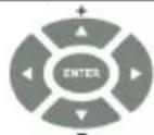
The MENU button shows the main OSD menu. The arrow buttons and ENTER button let you navigate within the OSD menu Volume
Press and hold to reset to the default resolution (helpful if you fail to see the input signal on the display)
Note that only the PC, HDMI and DisplayPort buttons on the remote control are applicable.
Contents
1 Introduction 1
2 Getting Started 2
2.1 Achieving the Best Performance 2
2.2 Safety Instructions 2
2.3 Recycling Kramer Products 3
3 Overview 4
3.1 HDCP Compliance 6
3.2 Defining the VP-461 Video Scaler 6
4 Connecting the VP-461 8
4.1 Audio Input Pinout 9
5 The OSD Menu 10
5.1 OSD Menu Operation Example 10
5.2 The Input Menu 13
5.3 The Audio Menu 19
5.4 The Process Menu 21
5.5 The Picture Menu 22
5.6 The Enhance Menu 23
5.7 The Scale Menu 24
5.8 The Miscellaneous Menu 27
6 The Display Modes 30
6.1 The Single Window Display Mode 30
6.2 The Dual Window Display Mode 30
7 Controlling the VP-461 35
7.1 Controlling via the Front Panel Buttons 35
7.2 Controlling via the OSD Menu 35
7.3 Connecting to the VP-461 via RS-232 36
7.4 Controlling via the Infrared Remote Control Transmitter 37
8 Flash Memory Upgrade 38
9 Technical Specifications 39
9.1 Default Communication Parameters 40
9.2 Input Resolutions 40
9.3 Output Resolutions 41
10 The VP-461 RS-232 Communication Protocol 42
10.1 Using the Communication Protocol 42
10.2 Communication Protocol: Mimicking OSD 42
10.3 Protocol Table: Mimicking Remote and Front Panel Buttons 50
10.4 The Protocol 3000 Common Operation Commands 50
Figures
Figure 1: VP-461 Video Scaler 6
Figure 2: Connecting the VP-461 Video Scaler 9
Figure 3: Audio Input Pinout 9
Figure 4: Input Menu 13
Figure 5: Select the Display Mode 15
Figure 6: changing the size of the Window 16
Figure 7: Increasing the Width 16
Figure 8: Increasing the Height 17
Figure 9: Positioning the Window 17
Figure 10: Window Customization 18
Figure 11: H-Position Slide Bar 18
Figure 12: Moving the PiP Window 19
Figure 13: Audio Menu 19
Figure 14: Set the Output Volume Level 20
Figure 15: Process Menu 21
Figure 16: Picture Menu 22
Figure 17: Enhance Menu 23
Figure 18: Scale Menu 24
Figure 19: Misc Menu 27
Figure 20: DP superimposed over PC 33
Figure 21: Infrared Remote Control Transmitter 37
1 Introduction
Welcome to Kramer Electronics! Since 1981, Kramer Electronics has been providing a world of unique, creative, and affordable solutions to the vast range of problems that confront video, audio, presentation, and broadcasting professionals on a daily basis. In recent years, we have redesigned and upgraded most of our line, making the best even better!
Our 1,000-plus different models now appear in 11 groups that are clearly defined by function: GROUP 1: Distribution Amplifiers; GROUP 2: Switchers and Routers; GROUP 3: Control Systems; GROUP 4: Format/Standards Converters; GROUP 5: Range Extenders and Repeaters; GROUP 6: Specialty AV Products; GROUP 7: Scan Converters and Scalers; GROUP 8: Cables and Connectors; GROUP 9: Room Connectivity; GROUP 10: Accessories and Rack Adapters and GROUP 11: Sierra Video Products.
Congratulations on purchasing your Kramer VP-461 Video Scaler. This product, which incorporates HDMI™ technology, is ideal for:
- Projection systems in conference rooms, boardrooms, auditoriums, hotels and churches, production studios, rental and staging
- Any application where high quality conversion and switching of multiple and different video signals to graphical data signals is required for projection purposes
2 Getting Started
We recommend that you:
- Unpack the equipment carefully and save the original box and packaging materials for possible future shipment
- Review the contents of this user manual

Go to http://www.kramerelectronics.com/support/product_downloads.asp to check for up-to-date user manuals, application programs, and to check if firmware upgrades are available (where appropriate).
2.1 Achieving the Best Performance
To achieve the best performance:
- Use only good quality connection cables (we recommend Kramer high-performance, high-resolution cables) to avoid interference, deterioration in signal quality due to poor matching, and elevated noise levels (often associated with low quality cables)
- Do not secure the cables in tight bundles or roll the slack into tight coils
- Avoid interference from neighboring electrical appliances that may adversely influence signal quality
• Position your Kramer VP-461 away from moisture, excessive sunlight and dust

This equipment is to be used only inside a building. It may only be connected to other equipment that is installed inside a building.
2.2 Safety Instructions

Caution: There are no operator serviceable parts inside the unit
Warning: Use only the Kramer Electronics input power wall adapter that is provided with the unit
Warning: Disconnect the power and unplug the unit from the wall before installing
2.3 Recycling Kramer Products
The Waste Electrical and Electronic Equipment (WEEE) Directive 2002/96/EC aims to reduce the amount of WEEE sent for disposal to landfill or incineration by requiring it to be collected and recycled. To comply with the WEEE Directive, Kramer Electronics has made arrangements with the European Advanced Recycling Network (EARN) and will cover any costs of treatment, recycling and recovery of waste Kramer Electronics branded equipment on arrival at the EARN facility. For details of Kramer's recycling arrangements in your particular country go to our recycling pages at http://www.kramerelectronics.com/support/recycling/.
3 Overview
The Kramer VP-461 is a high quality Video Scaler. It accepts one of three inputs: a computer graphics signal on a 15-pin HD connector, an HDMI and a DisplayPort signal. It scales the video, embeds the audio and outputs the signal to the HDMI output, as well as to the PC output together with an unbalanced audio output.
The VP-461 Video Scaler features:
- K-Storm™ Scaling Technology - Kramer's extremely high performance scaling technology. High-quality 3:2 and 2:2 pull down de-interlacing and full up and down scaling of computer graphics video input signals
- State-of-the-art video processing technology, with the highest quality de-interlacing, noise reduction, and scaling performance for both standard-definition and high-definition signals
- K-IIT XL™ Picture-in-Picture Image Insertion Technology - Ultra stable picture-in-picture, picture-and-picture and split screen capability, or fully customizable windows' size and position control
- Ultra Fast Fade-Thru-Black (FTB™) Switching - Video switching transitions are clean and ultra-fast. The video fades to black and the new input fades from black for smooth, glitch-free switching. The output signal provides constant sync so the display never glitches
- Advanced deinterlacing functions - including 3D comb filtering, film mode, diagonal correction and motion detection
- Scaled Outputs – HDMI and PC outputs simultaneously
- Output Resolutions – HDTV and Computer Graphics up to 2K and 1080p/UXGA with selectable refresh rates
- Multiple Aspect Ratio Selections – Follow input, follow output, best fit, letterbox
- Multi-Standard Video support - NTSC (3.58/4.43), PAL (M/N/60) and SECAM
- Input and output audio level adjustment
- Selectable Power Save modes for energy efficient usage
- HDCP Compliant - The HDCP (High Definition Content Protection) license agreement allows copy-protected data on the HDMI input to pass only to the HDMI output
In addition, the VP-461 Video Scaler:
- Includes luma keying via the PiP window
- Features advanced EDID management (native resolution and color depth) per input
- Analyzes the connected output's EDID for optimal scaling
- Supports picture zooming both on main and PiP window from 100% to 1600%, including separate V and H sharpness control
- Provides HDMI and PC input and output color space control
• Supports HDMI deep color for output
- Features vertical keystone operation
- Is HDTV and computer graphics compatible and the resolution can be up- or down-scaled as required (see output resolutions in Section 5.7)
- Comes with an On-Screen Display (OSD) for easy setup and adjustment, accessible via the IR remote control and via the front-panel buttons
- Has a non-volatile memory that retains the last settings used
• Supports firmware upgrade via RS-232
- Has an external 5V DC power source
Control your VP-461:
- Directly, via the front panel push buttons
- By RS-232 serial commands transmitted by a touch screen system, PC, or other serial controller
- Remotely, from the infrared remote control transmitter
The VP-461 is housed in a desktop enclosure, letting 2 units to be rack mounted side-by-side in a 1U rack space with the optional RK-1 rack adapter.
3.1 HDCP Compliance

If the HDMI signal is HDCP protected, it can only appear on the HDMI output if it is connected to an HDCP compliant display.
The VP-461 will not output a picture on an HDMI display that is not HDCP compliant, nor will a picture be shown on the PC output; instead it will show a black screen.
In the dual window display mode (see Section 6.2), even if only one of the inputs is HDCP protected, and is output to a non compliant display, it will affect the entire screen and turn it black.
3.2 Defining the VP-461 Video Scaler
This section defines the VP-461.
flowchart
graph TD
    A["1"] --> B["IR"]
    B --> C["PC"]
    C --> D["HDMI"]
    D --> E["DISPLAY/PORT"]
    E --> F["PIP"]
    F --> G["FREEZE"]
    G --> H["VOLUME"]
    H --> I["ENTER"]
    I --> J["MENU"]
    J --> K["RESET To 720xXGA"]
    K --> L["PANEL LOCK"]
    L --> M["+"]
    M --> N["-"]
    N --> O["Video Scaler"]
    style A fill:#f9f,stroke:#333
    style B fill:#ccf,stroke:#333
    style C fill:#cfc,stroke:#333
    style D fill:#fcc,stroke:#333
    style E fill:#cff,stroke:#333
    style F fill:#ffc,stroke:#333
    style G fill:#cfc,stroke:#333
    style H fill:#fcf,stroke:#333
    style I fill:#cff,stroke:#333
    style J fill:#ffc,stroke:#333
    style K fill:#cfc,stroke:#333
    style L fill:#fcc,stroke:#333
    style M fill:#cfc,stroke:#333
    style N fill:#cfc,stroke:#333
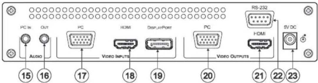
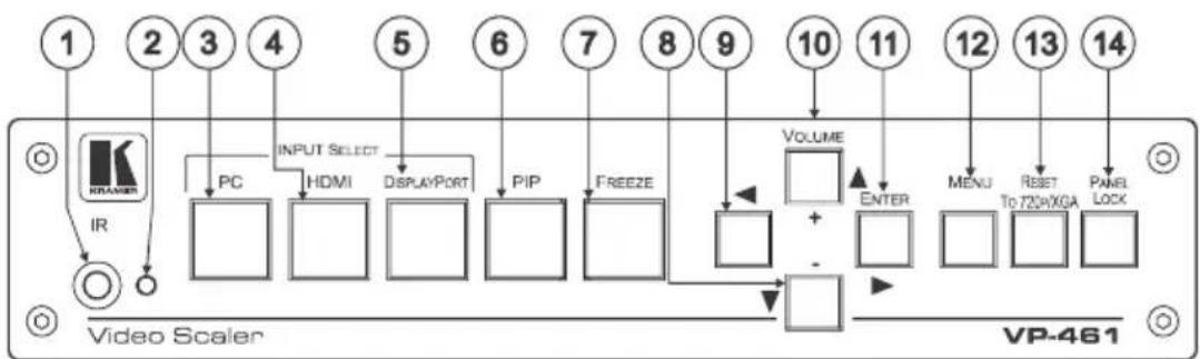
Figure 1: VP-461 Video Scaler
| # | Feature | Function | |
| 1 | IR Receiver | Accepts IR remote commands | |
| 2 | IR LED | Lights orange when the unit accepts IR remote commands | |
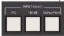
| 3 | INPUT SELECT Buttons | PC 15-pin HD | Press to select the computer graphics input |
| 4 | HDMI | Press to select the HDMI input | |
| 5 | DISPLAYPORT | Press to select the DisplayPort input | |
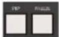
| 6 | PIP Button | Toggles the dual window mode (Picture-in-Picture) function (see Section 6.2)Note that while browsing the OSD menu in the dual window mode, a long press of the PIP button will instantly toggle the window control (between Main and PiP) | |
| 7 | FREEZE Button | Press to freeze/unfreeze the output video image | |
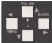
| 8 | Navigation Buttons | ▼/-VOLUME Button | Press to move down the menu list (see Section 7.1.1) and to decrease numerical values. When not within the OSD menu mode, press to reduce the output volume |
| 9 | ◀ Button | Press to exit the OSD menu and, when in the OSD menu, move to the previous level in the OSD screen (see Section 7.1.1) | |
| 10 | ▲/+ VOLUME Button | Press to move up the menu list values (see Section 7.1.1) and to increase numerical values. When not within the OSD menu mode, press to increase the output volume | |
| 11 | ▶ ENTER Button | Press to access sub-menu items and select from several settings (see Section 7.1.1) | |
| 12 | MENU Button | Press to access/exit the menu | |
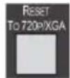
| 13 | RESET TO 720P/XGA Button | Press to reset the video output resolution to XGA or 720p and change the deep color settings to Off (see Section 5.7)Press and hold for about 3 seconds to toggle between reset to XGA and reset to 720p | |
| 14 | PANEL LOCK Button | Press and hold for about 3 seconds to lock/unlock the front panel buttons | |
| 15 | AUDIO PC IN 3.5mm Mini Jack Connector | Connect to the unbalanced audio of the computer graphics source (the pinout is defined in Section 4.1) | |
| 16 | AUDIO OUT 3.5mm Mini Jack Connector | Connect to an unbalanced stereo audio output | |
| 17 | VIDEO INPUT Connectors | PC | Connect to the computer graphics source |
| 18 | HDMI | Connect to the HDMI source | |
| 19 | DISPLAYPORT | Connect to the DisplayPort source | |
| 20 | VIDEO OUTPUT Connectors | PC 15-pin HD | Connect to a computer graphics acceptor |
| 21 | HDMI | Connect to an HDMI acceptor | |
| 22 | RS-232 9-pin D-sub Port | Connect to the PC or a remote controller | |
| 23 | 5V DC | +5V DC connector for powering the unit | |
4 Connecting the VP-461

Always switch off the power to each device before connecting it to your VP-461. After connecting your VP-461, connect its power and then switch on the power to each device.

You do not have to connect all the inputs and outputs, connect only those that are required.
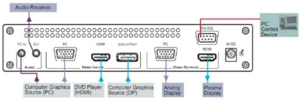
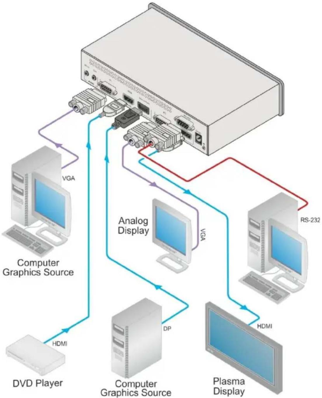
To connect the VP-461, as illustrated in the example in Figure 2, do the following:
- Connect a computer graphics source to the PC VIDEO INPUT 15-pin HD connector.
- Connect an HDMI source (for example, a DVD player) to the HDMI VIDEO INPUT connector.
Alternatively, you can connect the DVI connector on the DVD player to the HDMI connector on the VP-461 via a DVI-HDMI adapter - Connect a DisplayPort video source (for example, a computer graphics source) to the DISPLAYPORT VIDEO INPUT connector.
- Connect the audio input signal to the AUDIO PC IN 3.5mm mini jack (not shown in Figure 2).
- Connect the HDMI VIDEO OUTPUT connector to an HDMI acceptor (for example, a plasma display).
- Connect the PC VIDEO OUTPUT 15-pin HD connector to a VGA acceptor (for example, an analog display).
- Connect the AUDIO OUT 3.5mm mini jack to an audio acceptor, not shown in Figure 2.
- Connect a PC and/or controller to the RS-232 terminal block (see Section 7.3)
- Connect the 5V DC power adapter to the power socket and connect the adapter to the mains electricity (not shown in Figure 2).
flowchart
graph TD
    A["Device"] -->|VGA| B["Computer Graphics Source"]
    A -->|VGA| C["Analog Display"]
    A -->|VGA| D["RS-232"]
    A -->|HDMI| E["DVD Player"]
    A -->|HDMI| F["Computer Graphics Source"]
    A -->|HDMI| G["Plasma Display"]
    A -->|DP| H["Computer Graphics Source"]
Figure 2: Connecting the VP-461 Video Scaler
4.1 Audio Input Pinout
This section defines the audio input 3.5mm jack pinout.
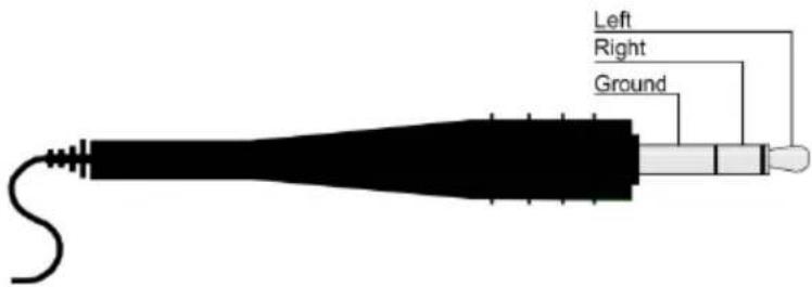
Figure 3: Audio Input Pinout
5 The OSD Menu
The VP-461 OSD menu lets you set the operation parameters for the:
- Main Window Control
- PIP Window Control
- Entire System Control
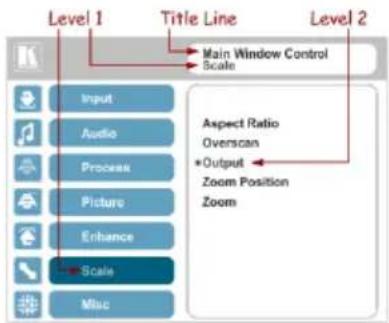
The nature of the operation setup appears in the OSD title, as shown in the example in Section 5.1:
- The title line shows the control mode (Main, PIP or Entire system)
• Level 1 lists the main menu items - Level 2 includes the second hierarchy level, below level 1
- Level 3 includes the third hierarchy level, below level 2
- Function, is the selectable parameter or numerical value and can appear either under level 2 or 3
5.1 OSD Menu Operation Example
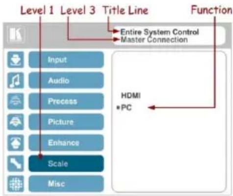
In the example illustrated below, the Master Connection is set to PC (see Section 5.7).
The table below shows function 632 (from the Protocol in Section 10.2.2):
- 6 in the hundreds, represents “Scale” which is the 6^th menu item in the main menu list
- 3 in the tens, represents "Output" which is 3^rd in the Scale menu
- 2 in the units, represents "Master Connection" which is second in the Output menu
| Level 1 | Level 2 | Level 3 | Level 4 (Function) | Range | Function |
| Scale (6) | Output (3) | Master Connection (2) | HDMI | 0 | 632 |
| PC | 1 |
The subtitle, below the title line shows the current level accessed (Scale in this example)
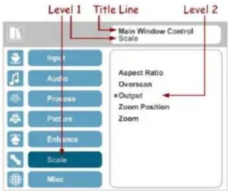
After selecting Output (which is the second Level), it appears in the subtitle
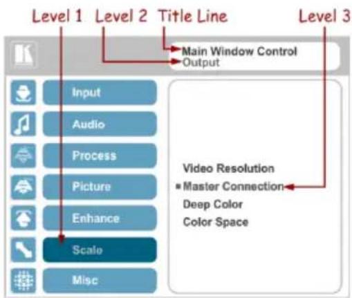
Once Master Connection is selected, the Title changes to "Entire System Control" indicating that the selection will affect the entire system. The subtitle shows the current, Level 3, selection and the menu list shows the function (PC)
If the display layout includes a PiP window, you can set the OSD menu to control the main source window and the PIP window separately (by defining Window Control, see Section 5.8).
General characteristics which apply to the entire system (for example, setting the volume) are changed without needing to shift control (the title line will state: Entire System Control).
Note that:
- A selected parameter that turns gray becomes valid immediately (there is no need to press Enter to save the changes)
- Exiting the menu saves the parameter to the memory
- Data is saved per window and per input (to a dedicated input + window memory), as applicable
The control buttons let you control the VP-461 via the OSD menu. Press the:
- MENU button to enter the menu, exit the menu, and when in the OSD menu, move to the previous level and change menu settings in the OSD screen. Changes are immediate
The default timeout is set to 30 seconds and can be changed (see Section 5.8)
- ENTER (or ▷) button to access sub-menu items
- Arrow buttons to move through the OSD menu
- Up or down arrows to change settings

Note that when exiting menu, all the changes are automatically saved to the non-volatile memory.
The default OSD timeout is set to 30 seconds and can be changed (see Section 5.8).
5.1.1 OSD Control Icons
The following three icons: M, P, and E are included to indicate when functionality applies to the Main window, the PiP Window or the entire system:
• for Main Window Control
• for PiP window Control
• for Entire System Control
5.2 The Input Menu
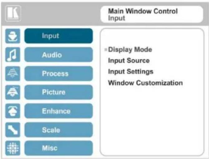
Figure 4: Input Menu
| Setting | Function |
| Display Mode | Select the display mode (see Figure 5):Single Window – single window mode operation with one channel displayedEPicture in Picture (PiP) – dual window mode operation, a smaller window superimposed over a full screen image (see Section 6.2)EPicture + Picture (PoP) – dual window mode operation, both images appear side-by-side and the aspect ratios of both images are maintained (see Section 6.2)ESplit (SbS) – dual window mode operation, both images are placed side-by-side with the same height (see Section 6.2)EWhen selecting a PiP configuration, set the Main window or the PiP window parameters via Misc -> OSD -> Window Control (see Section 5.8)Note that while browsing the OSD menu in the dual window mode, press of the PIP button to instantly toggle the window control (between Main and PiP)Customized –customized image size E Note that any change in the output resolution cancels the window customization Note that any change in the output resolution cancels the window customization |
| Input Source | Select the input source: PC, HDMI or DisplayPortM/FWhen selecting the PC input, it supports YPbPr and RGB color spaces and also supports sync on green. (see Color Space below) |
| Input Settings | Set the:H Image Shift– to set the horizontal position of the image within the windowM/PVolatile parameterV Image Shift– to set the vertical position of the image within the windowM/PVolatile parameterAuto Positioning– to search the input image during the tuning process and automatically position it on the output window in a perfect fit.Set to Offto disable auto positioningSet to Normal Scan to perform a normal range image searchSet to Wide Scan to perform a wide range image searchM/Fin the Normal/Wide Scan option, the machine automatically adjusts all the PC input video resolutions (PC 1 and PC 2). For the other inputs, the machine automatically adjusts all the input video resolutions except for HD/SD (CEA 861 standard) video resolutionsHDCP Mode– to select the HDCP option for the HDMI input: either ON (the default) or OFF.Setting HDCP mode to Off on the HDMI input allows the source to transmit a non-HDCP signal if required (for example, when working with a Mac computer).EDID Select– to select the native resolution on the input to be read by the video source connected to that input: 1024x768@60, 1280x800@60, 1280x1024@60, 1366x768@60, 1440x900@60, 1400x1050@60, 1600x900@60, 1600x1200@60, 1680x1050@60, 1920x1200@60RB, 720p50, 720p60, 1080p50, 1080p60 (default), 2K50 or 2K60Note that for the HDMI and DP inputs, you can either select the color depth to be 8bpp or 12bpp after selecting the native resolutionNote that when the EDID is set on the inputs, the changes are per  input and immediate.Color Space– to select the color space for the PC and HDMI inputs: RGB, YPbPr or Follow InputNote that if the machine is set to the dual display mode, and both the Main and PiP windows display the same input,-set the same input color space value for both windows input and immediate.Color Space– to select the color space for the PC and HDMI inputs: RGB, YPbPr or Follow InputNote that if the machine is set to the dual display mode, and both the Main and PiP windows display the same input,-set the same input color space value for both windows |
| Window Customization | Select the position and the size of the selected window: H Position, H Width, V Position and V Height (see Section 5.2.1.2and Section 5.2.1.1)M/PThe value range is dynamic, the FW prevents windows from exceeding boundaries or over-sizing and the position and size of the windows are saved to the system.The size and position of the customized window (main or PiP) remain valid even when toggling the PIP button (front panel, remote control transmitter or protocol command).The customized setup is run over only by explicitly selecting a preset Display Mode (see above in table).Only if a new setup is created or a preset display mode is selected, this new setup runs-over the current, customized, setup. The PiP window maximum horizontal active image area is 1600 pixels The PiP window maximum horizontal active image area is 1600 pixels |
The display mode setup, shown in Figure 5, is part of the entire system control and the selected Single Window also shows the current aspect ratio (Best Fit):
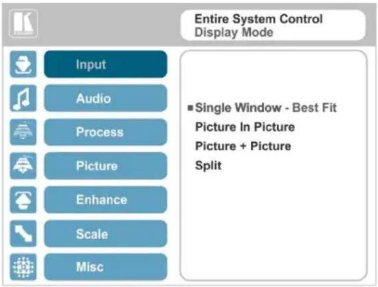
Figure 5: Select the Display Mode
5.2.1 Window Customization
Window customization lets you change the position and size of a selected window. Make sure that you have control over the window that requires customization (Main Window Control or PiP Window Control). If not, select it via the OSD item in the Miscellaneous menu, see Section 5.8.
In the following examples, PiP Window Control is selected, but the same procedure applies to Main Window Control.
5.2.1.1 Changing the Size of the Main and/or PiP Window
Use the H Width and V Height to change the size of the window using the + and - buttons on the front panel or remote control transmitter (as illustrated in Figure 6).
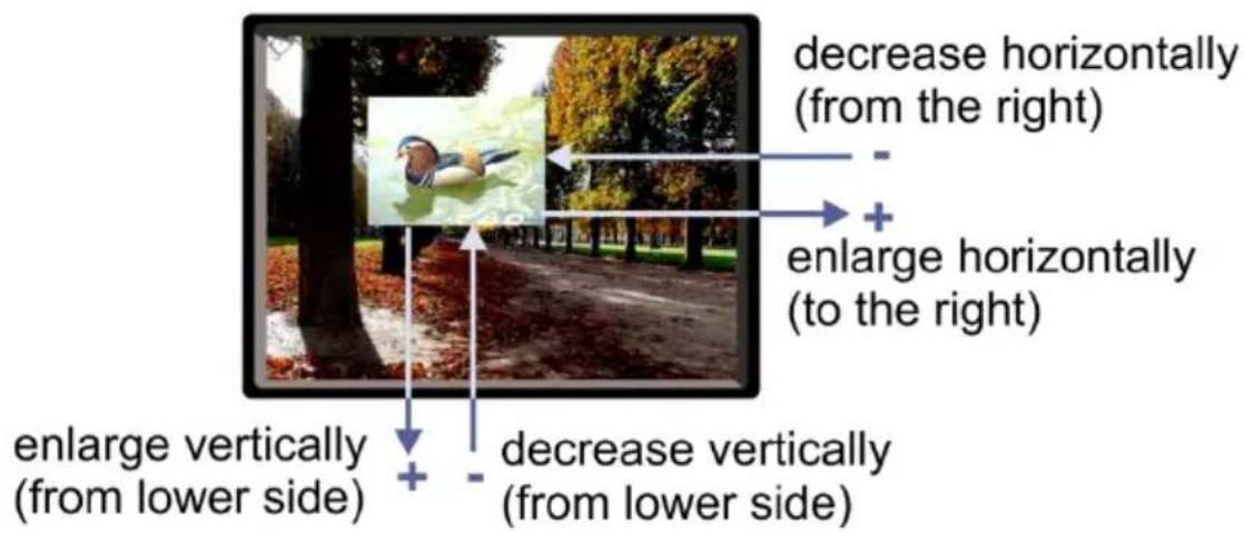
Figure 6: changing the size of the Window
To change the size of the window, do the following:
- Check that window control is set as required (for example, PiP Window Control).
- Select Window Customization (see Figure 10).
- Select H width (an OSD slide bar appears) and press + to increase the width, or – to decrease the width, see Figure 7.
The following example shows how to increase the width of the window
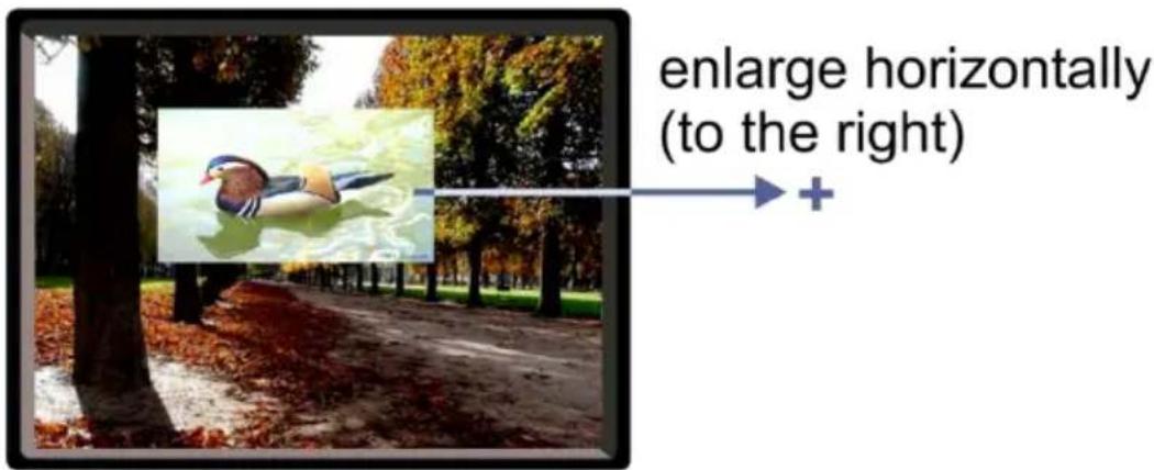
Figure 7: Increasing the Width
- Select V Height (an OSD slide bar appears) and press + to increase the height, or – to decrease the height, see Figure 8.
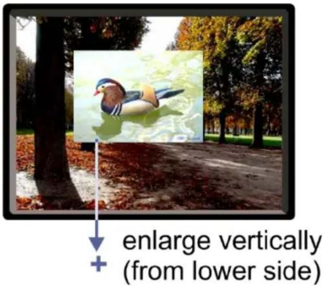
Figure 8: Increasing the Height
5.2.1.2 Moving the Position of the Main and/or PiP Window
Use the H Position and V Position items in the OSD to change the position of the window using the + and - buttons on the front panel or remote control transmitter (as illustrated in Figure 9).
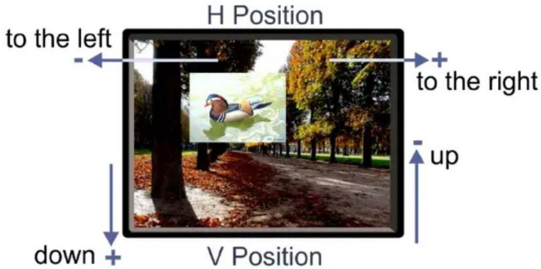
Figure 9: Positioning the Window
To move the position of the window, do the following:
- Check that window control is set as required (for example, PiP Window Control).
- Select Window Customization.
The following Window appears:
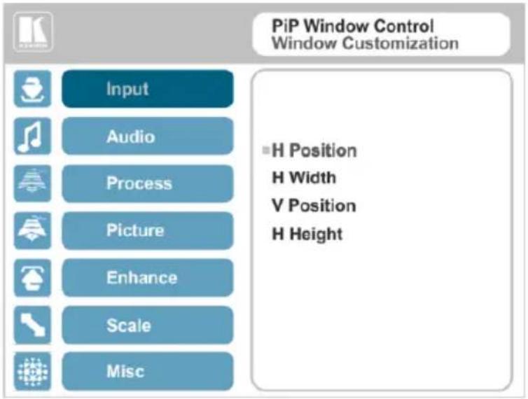
Figure 10: Window Customization
- To move the picture to the right, select H Position. An OSD slide bar appears:
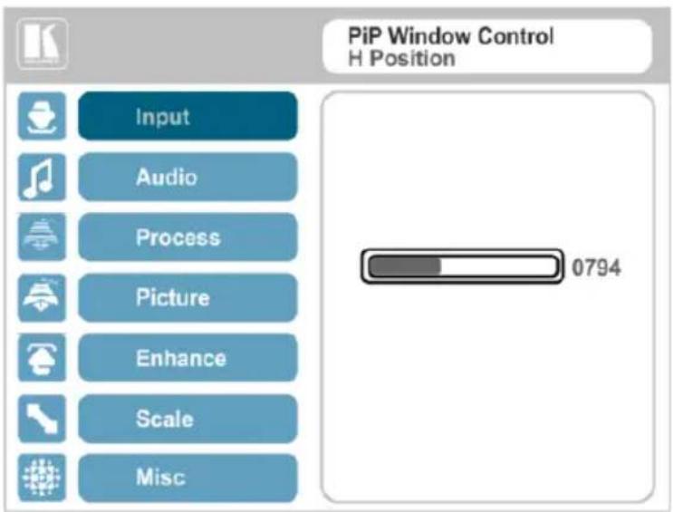
Figure 11: H-Position Slide Bar
- Press the +/- buttons to move the PiP window horizontally.
Use the V Position menu item in the same way to move the PiP vertically, see Figure 12.
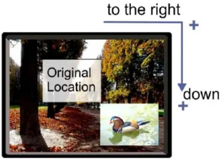
Figure 12: Moving the PiP Window

Note that the sequence in which you change the size and position of the window is insignificant, as long as you make sure that the resized image does not go beyond the window boundaries.
5.3 The Audio Menu
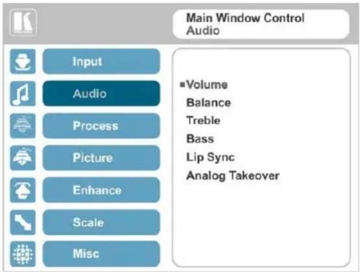
Figure 13: Audio Menu
| Setting | Function |
| Volume | Set the input/output volume level [dB], see Figure 14Input Volume [dB] – to adjust the audio input levelOutput level [dB] – to adjust the audio output levelThe output audio level can also be set via the + and – buttons on the front panel buttons (when not in the OSD mode) and/or the IR remote control transmitter buttons (see Section 7.4) |
| Balance | Set the balance [ratio] |
| Treble | Set the treble [dB] |
| Bass | Set the bass level [dB] |
| Lip Sync | Set the Lip Sync delay value [msec] |
| Analog Takeover | Set the Analog TakeoverOn – for the PC IN analog input to take over all the embedded inputsOff – to use the embedded inputsAs long as Analog Takeover is ON, the embedded audio is disabled |
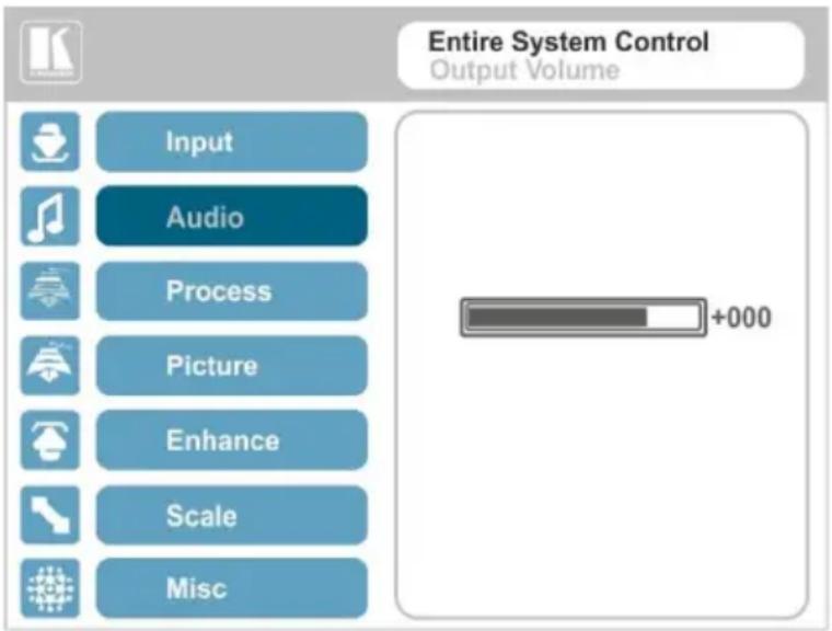
Figure 14: Set the Output Volume Level
5.4 The Process Menu

The Process menu functions are available for interlaced video processing only and not for progressive scan.
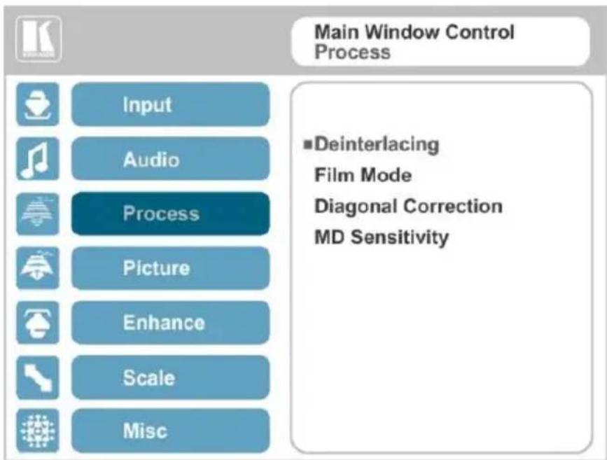
Figure 15: Process Menu
| Setting | Function |
| Deinterlacing | Set the deinterlacing method to:Line Doubler – to improve the quality of the image to some extentM/PLine doubler takes an interlaced scan, doubles the lines. The additional lines provide a better quality image and a brighter outputMotion adaptive– to produce a brighter smoother and higher resolution imageM/PSet the deinterlacing (per window) sync to:Current Field– for a long delayM/POlder Field– for a short delayM/PWhen selecting Older Field, diagonal correction is disabled |
| Film Mode | Set to:Off– for no pull-downM/PFollow Input– to automatically identify the required pull-down (2:2 or 3:2 pull-down)M/PM24PsF– to force 24PsF pull-downM/ |
| Diagonal Correction | Set the level of diagonal interpolation from 0 to 3.When set to the lower level, the diagonal image does not appear smoothM/ |
| MD Sensitivity | Set (from Level 1 to Level 5)M/PSelect the motion detection sensitivity for filtering of interlaced images. Set a high value for video where there is generally a large amount of motion, or a low value for little motion |
5.5 The Picture Menu
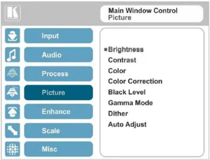
Figure 16: Picture Menu
| Setting | Function |
| Brightness | Set the brightness levelM/P |
| Contrast | Set the contrast levelM/P |
| Color | Set the color levelM/P |
| Color Correction | Set the blue, green and flesh color levels from 0 to 4M/P |
| Black Level | Set the black levelM/P |
| Gamma Mode | Set the gamma correction factor to Off, 0.4, 0.8, 1.2, 1.6, 2.0, 2.4 or 2.8The higher the value, the darker the image |
| Dither | Set the error diffusionE:Mode0: Disable error diffusionMode1: In-frame 8:6 conversionMode2: Intra-frame 8:6 conversionMode3: In-frame 10:8 conversionMode4: Intra-frame 10:8 conversionMode5: In-frame 12:10 conversionMode6: Intra-frame 12:10 conversion |
| Auto Adjust | Set the image color (back to its default values) and position per window (centers it correctly on the screen)M/PSee Auto Positioning menu item inSection 5.2Note that Auto Adjust is disabled when in the Freeze state |
5.6 The Enhance Menu
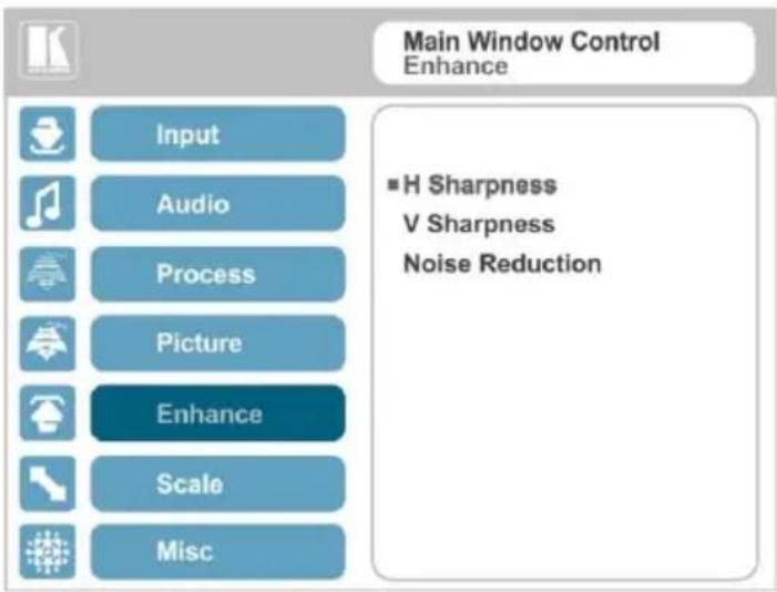
Figure 17: Enhance Menu
| Setting | Function |
| H Sharpness | Select the horizontal sharpness levelM/P |
| V Sharpness | Select the vertical sharpness levelM/P |
| Noise Reduction | Set the input noise reduction levels:Mosquito NR– the higher the level, the stronger the filtering of the imageM/PCombing NR– set to improve the quality of the subtitlesM/PTemporal NR– the higher the level, the stronger the filtering of the image. Useful when the noise is visible to the eyeM/PBlock NR– as the level is set higher, the block noise disappears and the image appears softerM/P Input noise reduction (except for Temporal NR) is enabled for interlaced video processing only and is inactive in the progressive scan. Input noise reduction (except for Temporal NR) is enabled for interlaced video processing only and is inactive in the progressive scan. |
5.7 The Scale Menu
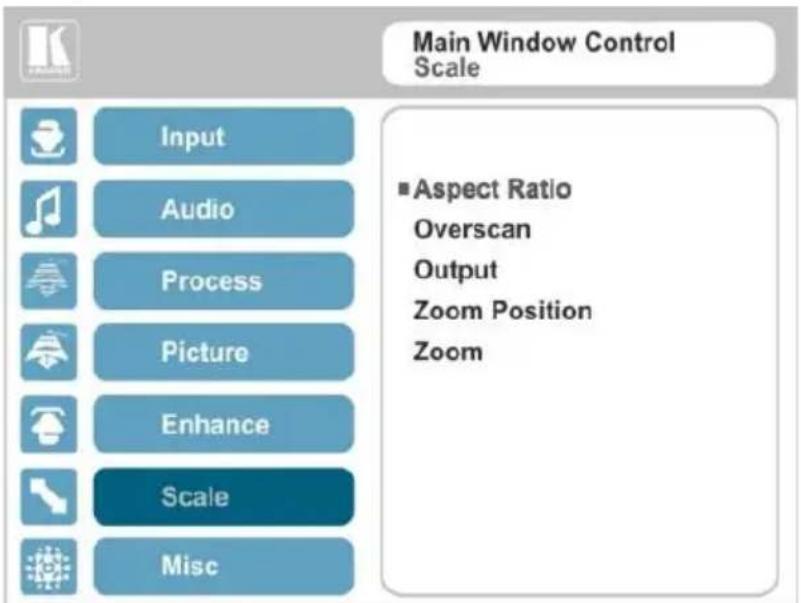
Figure 18: Scale Menu
| Setting | Function |
| Aspect Ratio | Set (seeSection 5.7.1) to:Follow Input– If the input resolution ≤ output resolution, display with a blank border.input >output is denied and the aspect ratio automatically changes to Follow OutputMFollow Output– If the input resolution ≤ output resolution, scale up the picture.If the input resolution ≥ output resolution, scale down the pictureMBest Fit– the best possible compromise between the input and the output aspect ratiosMLetterbox– to compress the top and bottom edges of the input signal, but fill the width of the screenMAPplies to the Single Window display mode only |
| Overscan | Set the overscan (per window) to Off, 5% or 10%MP |
| Output | Set the:Output Resolution– to Native, 640x480@60, 640x480@75, 800x600@50, 800x600@60, 800x600@75, 1024x768@50, 1024x768@60, 1024x768@75, 1280x768@50, 1280x768@60, 1280x800@60, 1280x1024@50, 1280x1024@60, 1280x1024@75, 1360x768@60, 1366x768@50, 1366x768@60, 1400x1050@50, 1400x1050@60, 1600x900@60, 1600x1200@50, 1600x1200@60, 1680x1050@60, 1920x1200@60, 480i60, 480p60, 576i50, 576p50, 720p50, 720p59.94, 720p60, 1080p23.976, 1080p24, 1080p25, 1080p29.97, 1080p30, 1080p50, 1080p59.94, 1080p60, 2K50, 2K60E Note that any change in the output resolution will cancel the zoom setting and window customizationMaster Connection– to HDMI or PC to determine the machine’s behavior (see Section 5.7.2)EIf the native resolution is not supported by the selected Master Connection, the system searches for the best supported resolution. If the search fails (for example, if the master connection is disconnected or EDID is unreadable), the resolution will default to XGA.Deep Color – to Off (the default) for 8-bit color depth or to Follow Output for applying deep color automatically on the HDMI output if supported by the display.Note that Follow Output sets the Deep Color of each output independently, according to the screen connected to each output. Note that any change in the output resolution will cancel the zoom setting and window customizationMaster Connection– to HDMI or PC to determine the machine’s behavior (see Section 5.7.2)EIf the native resolution is not supported by the selected Master Connection, the system searches for the best supported resolution. If the search fails (for example, if the master connection is disconnected or EDID is unreadable), the resolution will default to XGA.Deep Color – to Off (the default) for 8-bit color depth or to Follow Output for applying deep color automatically on the HDMI output if supported by the display.Note that Follow Output sets the Deep Color of each output independently, according to the screen connected to each output. |
 A change in the Deep Color setting will take effect after there is a hot plug on the HDMI output or if the user selects a new output resolution.Color Space – to RGB, YPbPr422 or YPbPr444 A change in the Deep Color setting will take effect after there is a hot plug on the HDMI output or if the user selects a new output resolution.Color Space – to RGB, YPbPr422 or YPbPr444 | |
| Zoom Position | Set H Position and V Position, the horizontal and vertical zoom positions respectively, to zoom into certain areas of the imageMPLets you “move” the zoom area (same as scanning an area with a magnifying glass) |
| Zoom | Set the zoomM/PZooms into the center of the displayWhen zooming in the Freeze state, in case the input resolution is larger than the output resolution, the image may be cut-off or change its position. This can be fixed via Zoom Position (above). |
 | Note that any change in the output resolution will cancel the zoom setting. |
5.7.1 Selecting the Correct Aspect Ratio
You can configure the aspect ratio of any output image to fit your application. The VP-461 offers four different aspect ratio settings: Follow Input, Follow Output, Best Fit and Letterbox. Here is how each of these settings works.
FOLLOW INPUT – The aspect ratio and resolution of the input video or graphics signal are both preserved (no scaling). For example, a composite video image with a 4:3 aspect ratio will appear with the same aspect ratio on a 1080p (16:9) output image, surrounded by black bars
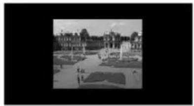
natural_image
Black-and-white exterior view of a grand public square with central fountain and surrounding buildings (no visible text or signage)FOLLOW OUTPUT – The aspect ratio and resolution of the input signal is re-sized to precisely match the aspect ratio and resolution of the VP-461 output signal. This may result in some distortion to the input signal images
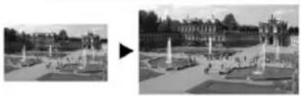
natural_image
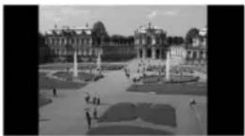
Exterior view of a grand fountain complex with multiple fountains and surrounding architecture (no signage or text visible)BEST FIT – This setting re-sizes the video or graphics input signal to "best fit" the output resolution while maintaining the aspect ratio of the input signal. For example, a composite video signal (4:3 aspect ratio) will "best fit" to the top and bottom of a widescreen output image, resulting in black pillars on either side.
natural_image
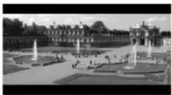
Black-and-white exterior view of a grand palace with symmetrical gardens and central towers (no visible text or signage)LETTERBOX – This setting compresses the top and bottom edges of the input signal, but fills the width of the screen. For example, to preserve a widescreen film image on a 4:3 display.
natural_image
Exterior view of a grand palace with fountains and manicured gardens (no signage or text visible)5.7.2 Master Connection Settings
The Master Connection (HDMI or PC) is usually set to the main output display so that the optimal resolution for that display can be obtained.
By setting the output resolution to Native, the VP-461 is triggered to read the EDID of the main display and change the output resolution value according to the native resolution of the display.
If it is not supported by the selected Master Connection, the system searches for the best supported resolution. If the search fails (for example, if the master connection is disconnected or EDID is unreadable), the resolution will default to XGA.
5.8 The Miscellaneous Menu
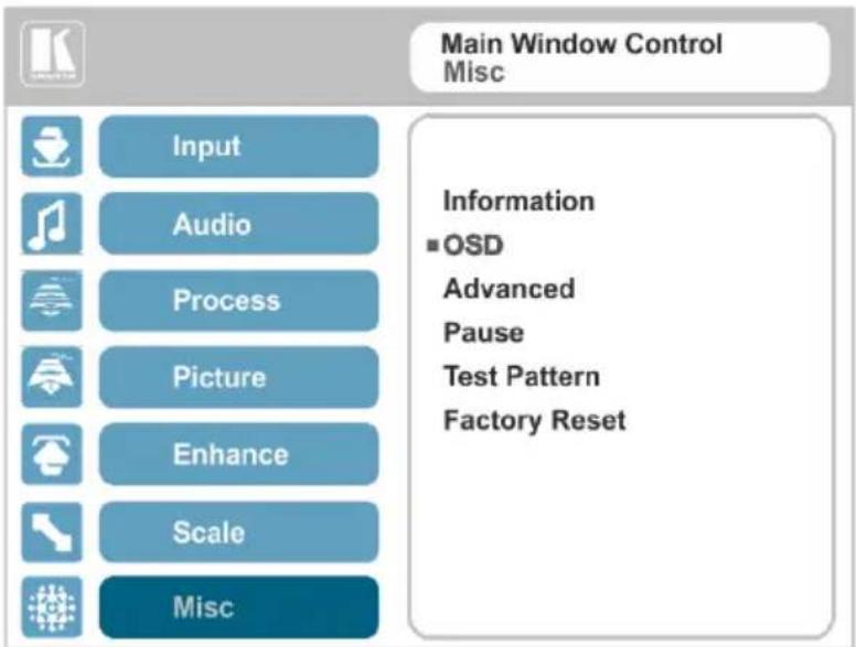
Figure 19: Misc Menu
| Setting | Function |
| Information | Displays the input resolution and frequency, the output resolution and firmware versionsEIf the selected output is the native output resolution, it will be displayed under "Native Output:"; in case of an explicit output resolution the title will be "Output:"If the input video is encrypted, an HDCP icon appears next to the input information |
| OSD | Set:Window Control– to Main Window Control to set the OSD menu to control the Main window (letting you select the input and other parameters for the main window) or to PiP Window Control to control the PiP window (letting you select the input and other parameters for the PiP window)EWhile browsing the OSD menu in the dual window mode, the window control can be toggled instantly with a long press of the PIP button on the front panel and a short press of the PIP button on the IR remote controller.Note that you can select the window control only when in the dual window modeH Position– to set the horizontal position of the OSDEEV Position– to set the vertical position of the OSDETransparency– to set the transparency to On or OffETransparency Gain– to set the transparency level (once set to transparent)ETransparency Bias– to set the transparency levelEBlink– to On for the selected item in the OSD to blink, or OffEBlink Period– to determine the blinking rateETimeout– to 30 seconds before OSD timeout, 60 seconds before OSD timeout or OFF (Off means that that the OSD appears continuously)E |
| Advanced | Set:V Keystone – to set the vertical keystone levelEUseful If the projector is located at an angle above or below the screen. In the OSD menu the value range shows -80 to 80. For interlaced inputs, this feature is disabledAuto Sync Off – to turn the auto sync On/Off.When ON, 2 minutes after not detecting a valid video signal on the selected input (or both inputs in the dual window mode), the unit will disable the syncs and the audio on all the outputs, until a valid input is again detected or any keypad button is pressed to activate the machine (once restored, the buttons return to their normal function)E When using the VP-461 for audio only, we recommend that you turn this feature offLuma Keying – to set the transparency level of the PIP window (see Section 5.8.1)E When using the VP-461 for audio only, we recommend that you turn this feature offLuma Keying – to set the transparency level of the PIP window (see Section 5.8.1)E |
| Pause | Set:Freeze – to ON to freeze the window (freezing the main window will also mute the audio output)MPPblank– to ON to display a blank window (blanking the main window will also mute the audio output)MP Note that any change in the input source may cancel the freeze and blank settings.Mute– to ON to mute the audio outputEA mute icon appears on screenDisable Outputs– to turn the sync and audio On/Off.When ON, the unit will disable the syncs and mute the audio output until any keypad button is pressedEOnce Disable Outputs is selected, a countdown appears, letting you cancel the process and revert to the previous state Note that any change in the input source may cancel the freeze and blank settings.Mute– to ON to mute the audio outputEA mute icon appears on screenDisable Outputs– to turn the sync and audio On/Off.When ON, the unit will disable the syncs and mute the audio output until any keypad button is pressedEOnce Disable Outputs is selected, a countdown appears, letting you cancel the process and revert to the previous state |
| Test Pattern | Set the Test pattern to Slide Bar (non-HDCP), Color Bar (HDCP) or Off.Each test pattern includes a sinusoid audio signal at 10dB @1kHz.We recommend that you set the Display Mode to Single Window (see Section 5.2) and set the Output Resolution to 1080p (see Section 5.7).Note that the Color Bar test pattern changes the OSD menu coloring and the following message appears on the display: “Ignore OSD Coloring” |
| Factory Reset | Reset to factory default values (see Section 9.1)EOnce Factory Reset is selected, a countdown appears, letting you cancel the process and revert to the previous state |
5.8.1 The Luma Keying Feature
The luma keying feature is an easy-to-use method of compositing two video sources into a single image. By setting up a “key” image or clip on a black background, it can be merged – or overlaid – onto the primary video. The key image is transparent in the areas of its dark background, resulting in a picture which looks as if the key image is cut out and pasted over the primary image. This useful function of combining images from two different sources is suitable for many applications, such as sub-titling, labeling, advertising or logo insertion.
To apply the luma keying feature, first set the PiP window to the desired size and location and then turn luma keying On. The PiP image will show without its background.
The lower the luminance in the PIP window, the more transparent it becomes, thus letting the main window image show. The higher the luminance, the less transparent it becomes, not letting the main window show through. To use this feature it is recommended to set the PIP image as follows: use low-luminance colors for the background (the key image portion) and high-luminance colors for the logo.

For certain displays, the screen may flicker once for about a second after activating or changing the luma keying setting.
Since luma keying is a volatile parameter, it may reset unexpectedly following a change in the setup. So we recommend that you activate it after completing the setup.
When the luma keying feature is On, any change in the setup (either by the user or by resetting due to a setup change) may cause the screen to flicker once. The luma keying will recover automatically after resetting.
6 The Display Modes
The VP-461 can function in the single window display mode (the factory default setup) or the dual window display mode.
6.1 The Single Window Display Mode
The single window mode shows one window on the screen. The window size can be customized, and its parameters modified via the OSD menu.
6.1.1 Activating the Single Window Mode
Set the VP-461 to the single window display mode in any of the following ways:
- Press and hold (for 3 seconds) the illuminated front panel PIP button until the button no longer illuminates
- Access the OSD menu, select INPUT>Display Mode, and then choose Single Window
- Press the PIP window on the remote control transmitter (see Section 7.4)
6.2 The Dual Window Display Mode
The VP-461 dual window mode feature lets you show two images on one screen: the main window and the PiP window. For example, you can show a live video window on top of a graphic background, or show two images on screen of the same input channel. The PiP window appears even if no input signals are connected. In this case the PiP window appears in dark gray and the main window appears in light gray.
The dual window mode appears in the following preset PiP configurations:
Picture-in-Picture, with a smaller PiP window superimposed over a full main window image

natural_image
Illustration of a colorful bird perched on a branch with an inset image of a giraffe in a savanna setting (no text or symbols)Picture + Picture, where both images appear side-by-side and the aspect ratios of both images are maintained

natural_image
Illustration of a colorful bird perched on a branch with an insect, alongside a separate image of a giraffe in a grassy field (no text or symbols)Split, where both images are placed side-by-side with the same height

natural_image
Split image showing a colorful bird in flight and a giraffe in a savanna landscape (no text or symbols)The window customization feature (see Section 5.2) lets you customize the dual window mode layout (main window and PiP window) to any size.

You can superimpose any input type over any or the same input type except for HDMI over PC or PC over HDMI
If the HDMI signal is HDCP protected, it can appear on the HDMI output that is connected to a supported HDCP compliant display. However, it cannot appear on a display that is not HDCP compliant and will show a black screen instead.
6.2.1 Activating the Dual window Mode
You can activate the dual window mode (indicated by an illuminated PIP front panel button) in any of the following ways:
- Press and hold (for 3 seconds) the front panel PIP button
The latest PiP configuration appears - Press the PIP button on the IR remote control transmitter (see Section 7.4)
The latest PiP configuration appears - Access the OSD menu, select INPUT>Display Mode, and then choose one
of the preset PiP configurations (Picture in Picture, Picture + Picture or Split)
6.2.2 Setting the OSD Menu to PiP Window Control
When the OSD menu is set to PiP Window Control, you can control the PiP window and change its parameters (for example, select the PiP input, size, position and so on). Section 6.2.3.3 shows how to select the PiP source via the OSD menu.
To set the OSD menu to PiP control:
- Press the MENU button to access the OSD menu.
- Scroll down to the Misc menu and press ENTER.
- Select the OSD submenu and press ENTER.
- Select Window Control and choose PIP WINDOW.
The OSD menu controls the PiP source - Press the MENU button to exit and accept changes.
The OSD menu title will show PiP Window Control. - You can press the MENU button several times to exit the menu and save
changes, or modify PiP window parameters via the other menu items.
To return to Main Window control, repeat the procedure above but select Main Window in the Window Control submenu.
6.2.3 Selecting the PIP Source
To select a PiP source you have to set the VP-461 to any of the PiP display mode configurations and then select the desired input.
6.2.3.1 Selecting the PiP Source via the Front Panel Buttons
Press and hold the PIP front panel button while pressing the input button of the required PiP source.
For example, to select DIssplayPort as the PiP source over PC as the main source, press the PIP front panel button while pressing the DIssplayPort front panel button (see Figure 20).
In this example, the PC button is illuminated and the DlssplayPort button blinks

natural_image
Composite image showing a group of zebrae resting in a muddy savanna with an inset photo of a bird feeding on a branch (no text or symbols visible)Figure 20: DP superimposed over PC
6.2.3.2 Selecting the PiP Source via the IR Remote Control Transmitter
Press the PIP button on the IR transmitter (the PIP front panel button is illuminated). Press the desired PiP source button on the IR transmitter (see Section 7.4).
6.2.3.3 Selecting the PiP Source via the OSD Menu

You can select an input source only after you set the display mode to one of the PiP configurations (see Section 6.2.1).
To set the PiP source via the OSD menu, do the following:
- Press the MENU button to access the OSD menu.
-
Scroll through the menu, and for window specific submenus check the menu title:
■ If PiP Window Control appears, continue to step 7
■ If not, continue to the next step -
Press the button to move to the Misc menu and press ENTER.
-
Select the OSD submenu and press ENTER.
-
Select Window Control and choose PiP Window Control. The OSD menu controls the PIP source
-
Press the MENU button a number of times to return to the main OSD menu (and accept changes).
-
Scroll to the Input menu and press ENTER.
-
Select Input Source and press ENTER.
-
Choose the input for the PiP window.
-
Press the MENU a few times until you exit the OSD menu (changes are saved upon exit).
7 Controlling the VP-461
The VP-461 can be controlled via:
• The front panel buttons (see Section 7.1)
• The OSD menu (see Section 7.2)
• The infrared remote control transmitter (see Section 7.4)
7.1 Controlling via the Front Panel Buttons
The VP-461 includes the following front panel buttons:
- Input selector buttons for selecting the required input: PC, HDMI and DisplayPort (see Section 7.1.1)
- PIP and FREEZE buttons (note, these buttons illuminate when selected)
- MENU, ENTER (right arrow), left arrow and up, down, arrow buttons
• Output Volume up (+) and down (-) buttons (when not in the OSD mode) - RESET TO 720p/XGA and PANEL LOCK buttons
7.1.1 Using the INPUT Front Panel buttons
When selected, an INPUT front panel button behaves as follows:
| Selecting the: | Causes the button to: |
| Main input button | Illuminate continuously |
| PiP input button | Blink (the light On period is shorter than the light Off period) |
| Same Main input button and PiP button | Blink (the light On period is longer than the light Off period) |

If you want to adjust the image of a selected input in a window, press that input button again (up to 3 times) for fast tuning. Pressing that input button for the fourth time initiates full tuning of the window.
7.2 Controlling via the OSD Menu
You can change PiP Window parameters, main window parameters and entire system parameters via the OSD menu, as described in Section 5.
7.3 Connecting to the VP-461 via RS-232
You can connect to the VP-461 via an RS-232 connection using, for example, a PC. Note that a null-modem adapter/connection is not required.
To connect to the VP-461 via RS-232, connect the RS-232 9-pin D-sub rear panel port on the VP-461 unit via a 9-wire straight cable (only pin 2 to pin 2, pin 3 to pin 3, and pin 5 to pin 5 need to be connected) to the RS-232 9-pin D-sub port on your PC.
7.4 Controlling via the Infrared Remote Control Transmitter

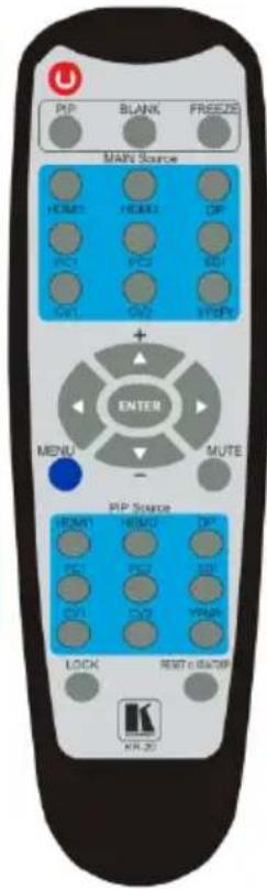
This IR remote control transmitter is compatible with various Kramer machines, therefore not all its buttons are applicable to the VP-461. The table below defines only the buttons that are relevant to the VP-461; the functionality of the other buttons is marked N/A.
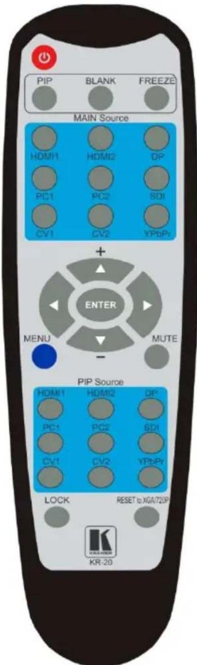
Figure 21: Infrared Remote Control Transmitter
| Keys | Function | |
| POWER | Toggle the power save mode ON or OFF | |
| PIP | Enter the dual window mode (the latest setting), see Section 6.2Note that while browsing the OSD menu in the dual window mode, a short press of the PIP button will instantly toggle the window control (between Main and PiP) | |
| FREEZE | Freeze/unfreeze the output video image (for both windows) | |
| MAIN Source Inputs | HDMI1 | Select the HDMI input |
| HDMI2 | N/A | |
| DP | Select the DisplayPort input | |
| PC1 | Select the UXGA input | |
| PC2 | N/A | |
| SDI | N/A | |
| CV1 | N/A | |
| CV2 | N/A | |
| YPbPr | N/A | |
 | Press ENTER to access menu levels (when in the OSD)Use the up and down arrows to adjust numerical values and adjust the output volume level (when not within the OSD) | |
| MENU | Enter/Exit the OSD menu and return to the previous menu level | |
| MUTE | Toggle between muting (blocking out the sound) and enabling the audio output | |
| PIP Source Inputs | HDMI1 | Select the HDMI input |
| HDMI2 | N/A | |
| DP | Select the DisplayPort input | |
| PC1 | Select the UXGA input | |
| PC2 | N/A | |
| SDI | N/A | |
| CV1 | N/A | |
| CV2 | N/A | |
| YPbPr | N/A | |
| LOCK | Lock the front panel buttons | |
| RESET to XGA/720P | Press to reset to the default resolution (toggles between RESET to XGA and 720p) | |
8 Flash Memory Upgrade
You can upgrade the VP-461 via the Kramer K-UPLOAD software. Two types of upgrade files are available for upgrade: video core and audio/graphics.

The latest firmware version, the Flash Memory Upgrade user guide, as well as the latest version of K-UPLOAD and installation instructions can be downloaded from the Kramer Web site at
http://www.kramerelectronics.com/support/product_downloads.asp
9 Technical Specifications
| INPUTS: | 1 VGA on a 15-pin HD connector1 HDMI (deep color) connector1 DisplayPort connector1 PC IN unbalanced stereo audio (1Vrms nom/100kΩ) on a 3.5mm mini jack connector |
| OUTPUTS: | 1 PC on a 15-pin HD connector1 HDMI (deep color) connector1 OUT unbalanced stereo audio on a 3.5mm mini jack connector |
| COMPLIANCE WITH HDMI STANDARD: | Supports HDMI (deep color) and HDCPSupports: DisplayPort 1.1a |
| OUTPUT RESOLUTIONS: | 640x480@60, 640x480@75, 800x600@50, 800x600@60, 800x600@75, 1024x768@50, 1024x768@60, 1024x768@75, 1280x768@50, 1280x768@60, 1280x800@60, 1280x1024@50, 1280x1024@60, 1280x1024@75, 1360x768p60, 1366x768@50, 1366x768@60, 1400x1050@50, 1400x1050@60, 1600x900@60, 1600x1200@50, 1600x1200@60, 1680x1050@60, 1920x1200@60, 480i60, 480p60, 576i50, 576p50, 720p50, 720p59.94, 720p60, 1080p23.976, 1080p24, 1080p25, 1080p29.97, 1080p30, 1080p50, 1080p59.94, 1080p60, 2K50, 2K60 |
| CONTROLS: | Front panel buttons, OSD, IR remote control, RS-232 on a 9-pin D-sub connector |
| OPERATING TEMPERATURE: | 0° to +40°C (32° to 104°F) |
| STORAGE TEMPERATURE: | -40° to +70°C (-49° to 158°F) |
| HUMIDITY: | 10% to 90%, RHL non-condensing |
| POWER SOURCE: | 5V DC 3.6A |
| DIMENSIONS: | 21.5cm x 16.3cm x 4.4cm (8.5" x 6.4" x 1.7") W, D, H |
| WEIGHT: | 1kg (2.2lbs) approx. |
| ACCESSORIES: | Power adapter (5.2V / 4A), IR remote control, control application program via RS-232 (PC) |
| OPTIONS: | RK-1 rack adapter |
| Specifications are subject to change without noticeFor the most updated resolution list, go to our Web site at http://www.kramerelectronics.com | |
9.1 Default Communication Parameters
RS-232
| Protocol | 3000 (Default) | |
| Baud Rate: | 115,200 | |
| Data Bits: | 8 | |
| Stop Bits: | 1 | |
| Parity: | None | |
| Command Format: | ASCII | |
| Example (Set display mode to Picture in Picture): | #Y 0,110,1 | |
| Full Factory Reset | ||
| Front panel buttons | Turn power off. Turn power on again while holding the RESET TO 720p/XGA front panel button. The LEDs light. Full factory reset is complete once the LEDs turn off one after the other and react normally | |
| OSD | Factory Reset through the Misc menu item | |
| Protocol 3000 | Use “Factory” command or #Y 0,760,1 | |
9.2 Input Resolutions
This section defines the input resolutions for each input
9.2.1 HDMI Input Resolutions
| HDMI Input Resolutions | ||||
| NTSC | 1080_I60 | 640x480_72 | 1024x768_70 | 1360x768_60 |
| PAL | 1080_P23_976 | 640x480_75 | 1024x768_75 | 1366x768_60 |
| 525_P60 | 1080_P24 | 640x480_85 | 1024x768_85 | 1440x900_60 |
| 625_P50 | 1080_P25 | 800x600_56 | 1152x864_75 | 1400x1050_60 |
| 720_P24 | 1080_P30 | 800x600_60 | 1280x800_60 | 1400x1050_75 |
| 720_P25 | 1080_P50 | 800x600_72 | 1280x960_85 | 1600x900_60 |
| 720_P30 | 1080_P60 | 800x600_75 | 1280x768_60 | 1600x1200_60 |
| 720_P50 | 2K50 | 800x600_85 | 1280x1024_60 | 1680x1050_60 |
| 720_P60 | 2K60 | 848x480_60 | 1280x1024_75 | 1920x1200_60RB |
| 1080_I50 | 640X480_60 | 1024x768_60 | 1280x1024_85 | |
9.2.2 PC Input Resolutions
| PC Input Resolutions | ||||
| 640X480_60 | 800x600_75 | 625_P50 | 1280x1024_60 | 1400x1050_75 |
| 640x480_72 | 800x600_85 | 525_P60 | 1280x1024_75 | 1600x900 60 |
| 640x480_75 | 1024x768_60 | 720_P50 | 1280x1024_85 | 1600x1200_60 |
| 640x480_85 | 1024x768_70 | 720_P60 | 1360x768_60 | 1680x1050_60 |
| 800x600_56 | 1024x768_75 | 1280x800_60 | 1366x768_60 | 1920x1200_60RB |
| 800x600_60 | 1024x768_85 | 1280x960_85 | 1440x900_60 | 1080_P50 |
| 800x600_72 | 1152x864_75 | 1280x768_60 | 1400x1050_60 | 1080_P60 |
9.2.3 DisplayPort Input Resolutions
| Display Port Input Resolution | |||
| 640X480_60 | 848x480_60 | 1280x768_60 | 1400x1050_75 |
| 640x480_75 | 1024x768_60 | 1280x1024_60 | 1600x900_60 |
| 640x480_85 | 1024x768_70 | 1280x1024_75 | 1680x1050_60 |
| 800x600_56 | 1024x768_75 | 1280x1024_85 | 1920x1200_60RB |
| 800x600_60 | 1024x768_85 | 1360x768_60 | 720_P60 |
| 800x600_72 | 1152x864_75 | 1366x768_60 | 1080_P60 |
| 800x600_75 | 1280x800_60 | 1440x900_60 | 2K50 |
| 800x600_85 | 1280x960_85 | 1400x1050_60 | 2K60 |
9.3 Output Resolutions
This section defines the output resolutions
9.3.1 HDMI Output Resolutions
| Technical Specifications of the HDMI Output Signal | |||
| 640x480@60 | 1280x1024@50 | 1680x1050@60 | 1080p25 |
| 640x480@75 | 1280x1024@60 | 1920x1200@60 | 1080p29.97 |
| 800x600@50 | 1280x1024@75 | 480i60 | 1080p30 |
| 800x600@60 | 1360x768@60 | 480p60 | 1080p50 |
| 800x600@75 | 1366x768@50 | 576i50 | 1080p59.94 |
| 1024x768@50 | 1366x768@60 | 576p50 | 1080p60 |
| 1024x768@60 | 1400x1050@50 | 720p50 | 2K50 |
| 1024x768@75 | 1400x1050@60 | 720p59.94 | 2K60 |
| 1280x768@50 | 1600x900@60 | 720p60 | |
| 1280x768@60 | 1600x1200@50 | 1080p23.976 | |
| 1280x800@60 | 1600x1200@60 | 1080p24 | |
9.3.1 PC Output Resolutions
| Technical Specifications of the PC Output Signal | |||
| 640x480@60 | 1280x1024@75 | 480p60 | 1080p29.97 |
| 640x480@75 | 1360x768@60 | 576i50 | 1080p30 |
| 800x600@60 | 1366x768@60 | 576p50 | 1080p50 |
| 800x600@75 | 1400x1050@60 | 720p50 | 1080p59.94 |
| 1024x768@60 | 1600x900@60 | 720p59.94 | 1080p60 |
| 1024x768@75 | 1600x1200@60 | 720p60 | 2K50 |
| 1280x768@60 | 1680x1050@60 | 1080p23.976 | 2K60 |
| 1280x800@60 | 1920x1200@60 | 1080p24 | |
| 1280x1024@60 | 480i60 | 1080p25 | |
10 The VP-461 RS-232 Communication Protocol
The Kramer Protocol lets you control the VP-461 from any standard terminal software (for example, the Windows ^® HyperTerminal Application).
10.1 Using the Communication Protocol
There are three different methods to control the VP-461 via RS-232:
- Protocol commands (via protocol 3000) mimicking the OSD, see Section 10.2
- The button functions mimicking the remote controller buttons (as well as the front panel buttons), see Section 10.3
• Protocol 3000 common commands, see Section 10.4

All three tables together include all the protocol commands, but they are not identical and do not always include the same information.
Some of the data may appear in one or two of the tables but not in the third table and vice versa.
The protocol 3000 communications protocol uses a data rate of 115200 baud, with no parity, 8 data bits, and 1 stop bit.
10.2 Communication Protocol: Mimicking OSD
The audio/video protocol commands defines all the function numbers, their valid parameters can be used with protocol 3000.
10.2.1 Using the Communication Protocol with Protocol 3000 (the "Y" Command)
Set Command:
Type in: "Y Control_Type=0,Function,Param"
Reply: "\~id=01Y Control_Type=0,Function,Param OK"
Set command example, set window control (721) to PiP:
Send: "#y 0,721,1"
Reply: "\~01@Y 0,721,1 OK"
Get Command:
Type in: "Y Control_Type=1,Function"
Result: "\~id=01Y Control_Type=1,Function,Param"
Get command example: get window control setup (721):
Send: "#y 1,721"
Result: "\~01@y 1,721,1"

You can add a last parameter, to be located fourth in SET or third in GET, to define a specific window.
For example:
Set H Sharpness value to 10 on the PiP window (1): “#y 0,510,10,1” Get H sharpness of the Main window (0): “#y 1,510,0”
The “Y” command also supports the value increment/decrement of any command using the ‘+’ or ‘-’ signs as the third parameter of the “Y” command.
For example, move the PiP window one step to the left
Send: "#Y 0,141,-,1
Reply: "\~01@Y 0,141,-,1 OK"
For example, in order to increase zoom on the main windows type "#Y 0,650,+,0
Send: "#Y 0,650,+,0
Reply: "\~01@Y 0,650,+,0 OK"
10.2.2 Protocol Table: Mimicking OSD
You can associate a function number to its description and valid parameters intuitively by navigating the OSD menu according to the following logic: A function number is directly related to its location in the OSD menu.
For example, the third menu on the OSD is Process (3 in the hundreds). The second menu item in Process is Film Mode (2 in the tens), therefore the function number for it will be 320 ( 3^rd item on the Main Window Control and the 2^nd item in the Process submenu (see also Section 5.1). When navigating in the OSD MENU you will be able to see the Film Mode valid parameters.
The following table defines the protocol commands:
| 1st Level | 2nd Level | 3rd Level | 4th Level | Range | Func. | Note |
| Input | Display Mode | Single Window | 0 | 110 | Single window also displays the aspect ratio in the OSD MENU | |
| Picture in Picture | 1 | |||||
| Picture + Picture | 2 | |||||
| Split | 3 | |||||
| Customized | 4 | |||||
| Input Source | HDMI | 13 | 120 | In case the window is inactive -1 will be returned | ||
| PC | 11 | |||||
| DP | 16 | |||||
| Input Settings | H Image Shift | 20:790 | 131 | Volatile Parameter | ||
| V Image Shift | 4:240 | 132 | ||||
| Auto Positioning | Off | 0 | 133 | Not applicable to HD/SD video types | ||
| Normal Scan | 1 | |||||
| Wide Scan | 2 | |||||
| HDCP Mode | On | 1 | 134 | |||
| Off | 0 | |||||
| EDID Select | 1024x768@60 | 0 | 135 | Applicable to input types with EDID only | ||
| 1280x800@60 | 1 | |||||
| 1280x1024@60 | 2 | |||||
| 1366x768@60 | 3 | |||||
| 1440x900@60 | 4 | |||||
| 1400x1050@60 | 5 | |||||
| 1600x900@60 | 6 | |||||
| 1600x1200@60 | 7 | |||||
| 1680x1050@60 | 8 | |||||
| 1920x1200@60RB | 9 | |||||
| 720p50 | 10 | |||||
| 720p60 | 11 | |||||
| 1080p50 | 12 | |||||
| 1080p60 | 13 | |||||
| 2K50 | 14 | |||||
| 2K60 | 15 | |||||
| Note; In case 8bpp is selected, set the color depth bit accordingly.The color depth bit is the MSB of PM.EDID_SEL (which represents the resolution).For example, when selecting 1600x900@60 at:8bpp, PM.EDID_SEL = 86h=134 dec12bpp, PM.EDID_SEL = 6h=6 dec | ||||||
| Color Space | RGB | 0 | 136 | Applicable to PC and HDMI inputs only | ||
| YPbPr | 1 | |||||
| Follow Input | 2 | |||||
| Window Customization | H Position | 0:2048 | 141 | The value range is dynamic. The FW prevents window overlapping and exceeding of boundariesThe PiP window horizontal value range is 0-1600 | ||
| H Width | 0:2048 | 142 | ||||
| V Position | 0:2048 | 143 | ||||
| V Height | 0:2048 | 144 | ||||
| Audio | Volume | Input Volume | -20:4 [dB] | 211 | Unavailable in audio pass-through | |
| Output Volume | -80:20 [dB] | 212 | ||||
| Balance | -10:10 [Ratio] | 220 | ||||
| Treble | -18:18 [dB] | 230 | ||||
| Bass | -18:18 [dB] | 240 | ||||
| Lip Sync | 0:90 [ms] | 250 | ||||
| Analog Takeover | 0:1 | 260 | ||||
| Process | Deinterlacing | Method | Line Doubler | 0 | 311 | Volatile parameter unavailable in progressive scan |
| Motion Adaptive | 1 | |||||
| Sync | Current Field | 0 | 312 | Unavailable in progressive scan. | ||
| Older Field | 1 | |||||
| Film Mode | Off | 0 | 320 | Unavailable in progressive scan | ||
| Follow Input | 1 | |||||
| 24PsF Mode | 2 | |||||
| Diagonal Correction | 0:3 | 330 | Unavailable in progressive scan. Unavailable when deinterlacing sync is older field | |||
| MD Sensitivity | LEVEL1 | 0 | 340 | Unavailable in progressive scan | ||
| LEVEL2 | 1 | |||||
| LEVEL3 | 2 | |||||
| LEVEL4 | 3 | |||||
| LEVEL5 | 4 | |||||
| Picture | Brightness | -400:400 | 410 | In the OSD menu the range appears as -80:80 | ||
| Contrast | 0.1:1.6 | 420 | ||||
| Color | 0.1:1.6 | 430 | ||||
| Color Correction | Blue | 0:4 | 441 | |||
| Green | 0:4 | 442 | ||||
| Flesh | 0:4 | 443 | ||||
| Black Level | -80:80 | 450 | ||||
| Gamma Mode | Gamma Off | 0 | 460 | |||
| Gamma 0.4 | 1 | |||||
| Gamma 0.8 | 2 | |||||
| Gamma 1.2 | 3 | |||||
| Gamma 1.6 | 4 | |||||
| Gamma 2.0 | 5 | |||||
| Gamma 2.4 | 6 | |||||
| Gamma 2.8 | 7 | |||||
| Dither | Mode0: Disable error diffusion | 0 | 470 | |||
| Mode1: In-frame 8:6 conversion | 1 | |||||
| Mode2: Intra-frame 8:6 conversion | 2 | |||||
| Mode3: In-frame 10:8 conversion | 3 | |||||
| Mode4: Intra-frame 10:8 conversion | 4 | |||||
| Mode5: In-frame 12:10 conversion | 5 | |||||
| Mode6: Intra-frame 12:10 conversion | 6 | |||||
| Auto Adjust | 0:1 | 480 | Self-clearing | |||
| Enhance | H Sharpness | -10:10 | 510 | |||
| V Sharpness | -10:10 | 520 | ||||
| Noise Reduction | Mosquito NR | 0:3 | 531 | Unavailable in progressive scan | ||
| Combing NR | 0:3 | 532 | ||||
| Temporal NR | 0:3 | 533 | ||||
| Block NR | 0:3 | 534 | Unavailable in progressive scan | |||
| Scale | Aspect Ratio | Follow input | 0 | 610 | 1. Single window only2. Customization lost3. In “Follow Input”, output must be bigger than input | |
| Follow Output | 1 | |||||
| Best Fit | 2 | |||||
| Letterbox | 3 | |||||
| Overscan | Off | 0 | 620 | |||
| 5% | 1 | |||||
| 10% | 2 | |||||
| Output | Video Resolution | Native | 0 | 6311. GET command in native mode returns the determined resolution of the master connection2. Special OSD MENU screen, follow OSD instructions | ||
| 640x480@60 | 1 | |||||
| 640x480@75 | 2 | |||||
| 800x600@50 | 3 | |||||
| 800x600@60 | 4 | |||||
| 800x600@75 | 5 | |||||
| 1024x768@50 | 6 | |||||
| 1024x768@60 | 7 | |||||
| 1024x768@75 | 8 | |||||
| 1280x768@50 | 9 | |||||
| 1280x768@60 | 10 | |||||
| 1280x800@60 | 11 | |||||
| 1280x1024@50 | 12 | |||||
| 1280x1024@60 | 13 | |||||
| 1280x1024@75 | 14 | |||||
| 1360x768@60 | 15 | |||||
| 1366x768@50 | 16 | |||||
| 1366x768@60 | 17 | |||||
| 1400x1050@50 | 18 | |||||
| 1400x1050@60 | 19 | |||||
| 1600x900@60 | 20 | |||||
| 1600x1200@50 | 21 | |||||
| 1600x1200@60 | 22 | |||||
| 1680x1050@60 | 23 | |||||
| 1920x1200@60 | 24 | |||||
| 480i60 | 25 | |||||
| 480p60 | 26 | |||||
| 576i50 | 27 | |||||
| 576p50 | 28 | |||||
| 720p50 | 29 | |||||
| 720p59.94 | 30 | |||||
| 720p60 | 31 | |||||
| 1080p23.976 | 32 | |||||
| 1080p24 | 33 | |||||
| 1080p25 | 34 | |||||
| 1080p29.97 | 35 | |||||
| 1080p30 | 36 | |||||
| 1080p50 | 37 | |||||
| 1080p59.94 | 38 | |||||
| 1080p60 | 39 | |||||
| 2K50 | 40 | |||||
| 2K60 | 41 | |||||
| Master Connection | HDMI | 0 | 632 | |||
| PC | 1 | |||||
| Deep Color | Off | 0 | 633 | |||
| Follow Output | 1 | |||||
| Color Space | RGB | 0 | 634 | |||
| YPbPr422 | 1 | Not applicable to PC output. Screen may flicker | ||||
| YPbPr444 | 2 | |||||
| Zoom Position | H Position | 0:2047 | 641 | Value range is dynamic, FW prevents zoom from exceeding the boundaries | ||
| V Position | 0:2047 | 642 | ||||
| Zoom | 1.0:16.0 | 650 | ||||
| Misc | Information | NTSC | 0 | 710 | READ ONLY: In the OSD MENU - Input, Output video formats & FW version. In the protocol - Get command returns the Input video format only | |
| PALM | 1 | |||||
| PAL60 | 2 | |||||
| N443 | 3 | |||||
| NTSC_4 | 4 | |||||
| SECAM | 5 | |||||
| PAL | 6 | |||||
| PALNC | 7 | |||||
| NTSC_8 | 8 | |||||
| N\A | 9 | |||||
| N\A | 10 | |||||
| N\A | 11 | |||||
| N\A | 12 | |||||
| N\A | 13 | |||||
| 525p60 | 14 | |||||
| 625p50 | 15 | |||||
| 720p60 | 16 | |||||
| 720p50 | 17 | |||||
| 720p24 | 18 | |||||
| 720p25 | 19 | |||||
| 720p30 | 20 | |||||
| 1080i60 | 21 | |||||
| 1080i50 | 22 | |||||
| N\A | 23 | |||||
| 1080i100 | 24 | |||||
| 1080p60 | 25 | |||||
| 1080p50 | 26 | |||||
| 1080p30 | 27 | |||||
| 1080p23_976 | 28 | |||||
| 1080p24 | 29 | |||||
| 1080p25 | 30 | |||||
| N\A | 31 | |||||
| N\A | 32 | |||||
| 640X480@60 | 33 | |||||
| N\A | 34 | |||||
| N\A | 35 | |||||
| N\A | 36 | |||||
| 640x480@72 | 37 | |||||
| 640x480@75 | 38 | |||||
| 848x480@60 | 39 | |||||
| 640x480@85 | 40 | |||||
| N\A | 41 | |||||
| 800x600@56 | 42 | |||||
| 800x600@60 | 43 | |||||
| N\A | 44 | |||||
| 800x600@72 | 45 | |||||
| 800x600@75 | 46 | |||||
| 800x600@85 | 47 | |||||
| 1024x768@60 | 48 | |||||
| 1360x768@60 | 49 | |||||
| 1280x768@60 | 50 | |||||
| 1024x768@70 | 51 | |||||
| 1024x768@75 | 52 | |||||
| 1280x800@60 | 53 | |||||
| 1024x768@85 | 54 | |||||
| 1400x1050@60 | 55 | |||||
| 1400x1050@75 | 56 | |||||
| 1440x900@60 | 57 | |||||
| 1152x864@75 | 58 | |||||
| 1600x900@60 | 59 | |||||
| 1280x1024@60 | 60 | |||||
| 1280x1024@75 | 61 | |||||
| 1280x960@85 | 62 | |||||
| 1920x1200@60RB | 63 | |||||
| 1280x1024@85 | 64 | |||||
| 1600x1200@60 | 65 | |||||
| 1680x1050@60 | 66 | |||||
| NONE | 0XF5 or 0XFF | |||||
| OSD | Window Control | Main Win | 0 | 721 | When in the single window mode, only Main Win is valid | |
| PiP Win | 1 | |||||
| H Position | 0:2047 | 722 | The value range is dynamic, FW prevents exceeding of boundaries | |||
| V Position | 0:2047 | 723 | ||||
| Transparency | ON | 1 | 724 | |||
| OFF | 0 | |||||
| Transparency Gain | 0.1:1.6 | 725 | ||||
| Transparency Bias | -400:400 | 726 | ||||
| Blink | ON | 1 | 727 | |||
| OFF | 0 | |||||
| Blink Period | 0.1:1.6 | 728 | ||||
| Timeout | Off | 0 | 729 | |||
| 30 Sec | 1 | |||||
| 60 Sec | 2 | |||||
| Advanced | Vertical Keystone | -400:400 | 731 | In the OSD menu the value range shows -80:80. Unavailable for interlaced output | ||
| Auto Sync Off | On | 1 | 732 | Two idle minutes are required to trigger screen shutdown | ||
| Off | 0 | |||||
| Luma Keying | On | 1 | 733 | Volatile parameter. Screen may flicker. Keying the PiP window | ||
| Off | 0 | |||||
| Pause | Freeze | On | 1 | 741 | ||
| Off | 0 | |||||
| Blank | On | 1 | 742 | |||
| Off | 0 | |||||
| Mute | On | 1 | 743 | In the Pip Mode, applies to main window only | ||
| Off | 0 | |||||
| Disable Outputs | On | 1 | 744 | Follow OSD instructions | ||
| Off | 0 | |||||
| Test Pattern | Off | 0 | 750 | |||
| Slide Bar | 1 | Non-HDCP content sinusoid sound | ||||
| Color Bar | 2 | HDCP content sinusoid sound | ||||
| Factory Reset | 0:1 | 760 | Follow OSD instructions. Self-clearing. | |||
10.3 Protocol Table: Mimicking Remote and Front Panel Buttons
The keystroke codes operate in the following way:
SET command third param =0,
Syntax example: "#Y 0,10,0
GET command for keystrokes will return ERR
The following table defines the keystroke function codes:
| Button | Keystroke Code | Button | Keystroke Code | Button | Keystroke Code |
| MENU | 10 | FREEZE | 17 | CH2_DP | 35 |
| ENTER | 11 | LOCK | 18 | MUTE | 37 |
| MINUS | 12 | CH1_VGA1 | 21 | POWER | 38 |
| PLUS | 13 | CH1_HDMI1 | 23 | LEFT | 39 |
| RESET | 14 | CH1_DP | 26 | RIGHT | 40 |
| PIP | 15 | CH2_VGA1 | 30 | DUMMY | 99 |
| BLANK | 16 | CH2_HDMI1 | 32 |
10.4 The Protocol 3000 Common Operation Commands
| Operation commands | ||
| Command | Syntax | Response |
| Lock front panel | LOCK-FP LOCK-MODEShort form: LCK LOCK-MODE | LOCK-FP LOCK-MODERESULT |
| See SV commands for SV version of this command | ||
| Get front panel locking state | LOCK-FP? | LOCK-FP LOCK-MODE |
| See SV commands for SV version of this commandParameters Description:LOCK-MODE= Front panel locking state:"0" or "off" to unlock front panel buttons."1" or "on" to lock front panel buttons. | ||
| Restart device | RESET | RESET OK |
| Firmware update execute* | UPGRADE | UPGRADE OK |
| Reset configuration to factory default | FACTORY | FACTORY RESULT |
| Set SN # | FCT-SN SN# | FCT-SN SN# RESULT |
| Audio/video common commands | ||
| Command | Syntax | Response |
| Output volume | VOLUME VOLUME-PARAMETER | VOLUME VOLUME-PARAMETER RESULT |
| Get output volume | VOLUME? | VOLUME VOLUME-VALUE |
| Parameters Description: VOLUME-PARAMETER = output volume parameters: [VALUE] either positive or negative digits (minus sign precedes negative values). “+” increase current value, “-” decrease current value | ||
| Win-customization | WIN-CUST WINDOW HPOS, HW, VPOS, VH | WIN-CUST WINDOW HPOS, HW, VPOS, VH RESULT |
| Parameters Description: fast window customization [WINDOW] “0” for main window; “1” for PiP window [HPOS] horizontal position value [HW] horizontal width value [VPOS] vertical position value [VH] vertical height value | ||
| Set dual window state | PIP PiP-MODE | PIP PiP-MODE RESULT |
| Get dual window state | PIP? | PIP PiP-MODE |
| Parameters Description: PiP-MODE = Dual window state: "0" or "off" for single window. "1" or "on" to for dual window. | ||
| Identification commands | ||
| Command | Syntax | Response |
| Protocol Handshaking | #CR | ~OK CRLF |
| Read device model | MODEL? | MODEL MACHINE_MODEL |
| Read device serial number | SN? | SN SERIAL_NUMBER |
| Read device firmware version | VERSION? | VERSION MAJOR. MINORBUILD. REVISION |
| Read device build date | BUILD-DATE? | BUILD-DATE YYYY/MM/DDHH:MM:SS |
| Read device protocol version | PROT-VER? | PROT-VER 3000: MAJORMINOR |
| Set machine name | NAME MACHINE_NAME | NAME MACHINE_NAME RESULT |
| Read machine name | NAME? | NAME MACHINE_NAME |
| Reset machine name to factory default* | NAME-RST | NAME-RST RESULT |
| Load firmware | Step 1: LDFWSIZEResponse 1: READY or LDFWSSIZEERR###Step 2: Ifreadywas received, sendFIRMWARE_DATAPResponse 2: LDFWSSIZERESULT |
| Load new audio\graphics memory file. | Step 1: LDMFSIZEResponse 1: READY or LDMFSSIZEERR###Step 2: Ifreadywas received, sendFIRMWARE_DATAPResponse 2: LDMFSSIZERESULT |
LIMITED WARRANTY
The warranty obligations of Kramer Electronics for this product are limited to the terms set forth below:
What is Covered
This limited warranty covers defects in materials and workmanship in this product.
What is Not Covered
This limited warranty does not cover any damage, deterioration or malfunction resulting from any alteration, modification, improper or unreasonable use or maintenance, misuse, abuse, accident, neglect, exposure to excess moisture, fire, improper packing and shipping (such claims must be presented to the carrier), lightning, power surges, or other acts of nature. This limited warranty does not cover any damage, deterioration or malfunction resulting from the installation or removal of this product from any installation, any unauthorized tampering with this product, any repairs attempted by anyone unauthorized by Kramer Electronics to make such repairs, or any other cause which does not relate directly to a defect in materials and/or workmanship of this product. This limited warranty does not cover cartons, equipment enclosures, cables or accessories used in conjunction with this product.
Without limiting any other exclusion herein, Kramer Electronics does not warrant that the product covered hereby, including, without limitation, the technology and/or integrated circuit(s) included in the product, will not become obsolete or that such items are or will remain compatible with any other product or technology with which the product may be used.
How Long Does this Coverage Last
Seven years as of this printing; please check our Web site for the most current and accurate warranty information.
Who is Covered
Only the original purchaser of this product is covered under this limited warranty. This limited warranty is not transferable to subsequent purchasers or owners of this product.
What Kramer Electronics will do
Kramer Electronics will, at its sole option, provide one of the following three remedies to whatever extent it shall deem necessary to satisfy a proper claim under this limited warranty:
-
Elect to repair or facilitate the repair of any defective parts within a reasonable period of time, free of any charge for the necessary parts and labor to complete the repair and restore this product to its proper operating condition. Kramer Electronics will also pay the shipping costs necessary to return this product once the repair is complete.
-
Replace this product with a direct replacement or with a similar product deemed by Kramer Electronics to perform substantially the same function as the original product.
-
Issue a refund of the original purchase price less depreciation to be determined based on the age of the product at the time remedy is sought under this limited warranty.
What Kramer Electronics will not do Under This Limited Warranty
If this product is returned to Kramer Electronics or the authorized dealer from which it was purchased or any other party authorized to repair Kramer Electronics products, this product must be insured during shipment, with the insurance and shipping charges prepaid by you. If this product is returned uninsured, you assume all risks of loss or damage during shipment. Kramer Electronics will not be responsible for any costs related to the removal or re-installation of this product from or into any installation. Kramer Electronics will not be responsible for any costs related to any setting up this product, any adjustment of user controls or any programming required for a specific installation of this product.
How to Obtain a Remedy under this Limited Warranty
To obtain a remedy under this limited warranty, you must contact either the authorized Kramer Electronics reseller from whom you purchased this product or the Kramer Electronics office nearest you. For a list of authorized Kramer Electronics resellers and/or Kramer Electronics authorized service providers, please visit our web site at www.kramerelectronics.com or contact the Kramer Electronics office nearest you.
In order to pursue any remedy under this limited warranty, you must possess an original, dated receipt as proof of purchase from an authorized Kramer Electronics reseller. If this product is returned under this limited warranty, a return authorization number, obtained from Kramer Electronics, will be required. You may also be directed to an authorized reseller or a person authorized by Kramer Electronics to repair the product.
If it is decided that this product should be returned directly to Kramer Electronics, this product should be properly packed, preferably in the original carton, for shipping. Cartons not bearing a return authorization number will be refused.
Limitation on Liability
THE MAXIMUM LIABILITY OF KRAMER ELECTRONICS UNDER THIS LIMITED WARRANTY SHALL NOT EXCEED THE ACTUAL PURCHASE PRICE PAID FOR THE PRODUCT. TO THE MAXIMUM EXTENT PERMITTED BY LAW, KRAMER ELECTRONICS IS NOT RESPONSIBLE FOR DIRECT, SPECIAL, INCIDENTAL OR CONSEQUENTIAL DAMAGES RESULTING FROM ANY BREACH OF WARRANTY OR CONDITION, OR UNDER ANY OTHER LEGAL THEORY. Some countries, districts or states do not allow the exclusion or limitation of relief, special, incidental, consequential or indirect damages, or the limitation of liability to specified amounts, so the above limitations or exclusions may not apply to you.
Exclusive Remedy
TO THE MAXIMUM EXTENT PERMITTED BY LAW, THIS LIMITED WARRANTY AND THE REMEDIES SET FORTH ABOVE ARE EXCLUSIVE AND IN LIEU OF ALL OTHER WARRANTIES, REMEDIES AND CONDITIONS, WHETHER ORAL OR WRITTEN, EXPRESS OR IMPLIED. TO THE MAXIMUM EXTENT PERMITTED BY LAW, KRAMER ELECTRONICS SPECIFICALLY DISCLAIMS ANY AND ALL IMPLIED WARRANTIES, INCLUDING, WITHOUT LIMITATION, WARRANTIES OF MERCHANTABILITY AND FITNESS FOR A PARTICULAR PURPOSE. IF KRAMER ELECTRONICS CANNOT LAWFULLY DISCLAIM OR EXCLUDE IMPLIED WARRANTIES UNDER APPLICABLE LAW, THEN ALL IMPLIED WARRANTIES COVERING THIS PRODUCT, INCLUDING WARRANTIES OF MERCHANTABILITY AND FITNESS FOR A PARTICULAR PURPOSE, SHALL APPLY TO THIS PRODUCT AS PROVIDED UNDER APPLICABLE LAW.
IF ANY PRODUCT TO WHICH THIS LIMITED WARRANTY APPLIES IS A "CONSUMER PRODUCT" UNDER THE MAGNUSON-MOSS WARRANTY ACT (15 U.S.C.A. §2301, ET SEQ.) OR OTHER APPLICABLE LAW, THE FOREGOING DISCLAIMER OF IMPLIED WARRANTIES SHALL NOT APPLY TO YOU, AND ALL IMPLIED WARRANTIES ON THIS PRODUCT, INCLUDING WARRANTIES OF MERCHANTABILITY AND FITNESS FOR THE PARTICULAR PURPOSE, SHALL APPLY AS PROVIDED UNDER APPLICABLE LAW.
Other Conditions
This limited warranty gives you specific legal rights, and you may have other rights which vary from country to country or state to state.
This limited warranty is void if (i) the label bearing the serial number of this product has been removed or defaced, (ii) the product is not distributed by Kramer Electronics or (iii) this product is not purchased from an authorized Kramer Electronics reseller. If you are unsure whether a reseller is an authorized Kramer Electronics reseller, please visit our Web site at
www.kramerelectronics.com or contact a Kramer Electronics office from the list at the end of this document.
Your rights under this limited warranty are not diminished if you do not complete and return the product registration form or complete and submit the online product registration form. Kramer Electronics thanks you for purchasing a Kramer Electronics product. We hope it will give you years of satisfaction.

For the latest information on our products and a list of Kramer distributors, visit our Web site where updates to this user manual may be found.
We welcome your questions, comments, and feedback.
Web site: www.kramerelectronics.com
E-mail: info@kramerel.com


SAFETY WARNING
Disconnect the unit from the power supply before opening and servicing

P/N: 2900-300195

Rev: 1