VS-8UFX - Switch Kramer - Free user manual and instructions
Find the device manual for free VS-8UFX Kramer in PDF.

| Product Type | 8x1 UXGA/Audio Switcher |
| Model | VS-8UFX |
| Inputs | 8x UXGA (15-pin HD) + 8x unbalanced stereo audio (RCA) |
| Outputs | 1x UXGA + 1x unbalanced stereo audio (RCA) |
| Maximum Resolution | UXGA (1600x1200 @ 60 Hz) |
| Video Bandwidth | 300 MHz (-3dB) |
| Audio Bandwidth | 20 Hz – 20 kHz |
| Control Interface | Front panel push buttons, RS-232 (DB-9), infrared remote (optional) |
| Power Supply | 100-240V AC, 50/60 Hz, 15W (internal) |
| Dimensions (W x D x H) | 19" x 7.5" x 1U (483 x 190 x 44 mm) |
| Weight | 2.5 kg (5.5 lbs) |
| Rackmountable | Yes, 1U height including rack ears |
| Operating Temperature | 0°C to 40°C (32°F to 104°F) |
| Storage Temperature | -20°C to 70°C (-4°F to 158°F) |
| Humidity | 10% to 90% non-condensing |
| Front Panel Indication | Input selection LEDs, power LED |
| Switching Method | Push-button and RS-232 command |
| Video Connector Type | 15-pin HD female (VGA) |
| Audio Connector Type | RCA female (unbalanced) |
| Included Accessories | Power cord, rack ears, rubber feet, user manual |
| Cleaning Instructions | Disconnect power, wipe with dry soft cloth; do not use liquids or sprays |
| Safety Precautions | Use grounded outlet, avoid exposure to moisture, do not open casing |
| Spare Parts and Repairability | Contact Kramer Electronics support; no user-serviceable parts inside |
| General Information | Use only with Kramer approved cables; refer to manual for full setup |
Frequently Asked Questions - VS-8UFX Kramer
User questions about VS-8UFX Kramer
0 question about this device. Answer the ones you know or ask your own.
Ask a new question about this device
Download the instructions for your Switch in PDF format for free! Find your manual VS-8UFX - Kramer and take your electronic device back in hand. On this page are published all the documents necessary for the use of your device. VS-8UFX by Kramer.
USER MANUAL VS-8UFX Kramer
Contents
Introduction 1
Getting Started 1
Overview 2
Defining ASPEN-32UFX, ASPEN-1616UX, VS-8UFX 12G SDI Matrix Switcher 4
Installing in a Rack 7
Connecting ASPEN-32UFX, ASPEN-1616UX, VS-8UFX 8
Connecting ASPEN 32UFX, ASPEN 1616UX 8
Connecting VS-8UFX 9
Configuring ASPEN-32UFX, ASPEN-1616UX, VS-8UFX 10
Configuring – Web Pages 10
Configuring - Front Panel 20
Operating ASPEN-32UFX, ASPEN-1616UX, VS-8UFX 21
Operating – Web Pages 21
Operating - Front Panel Buttons 23
Technical Specifications 25
Default Communication Parameters 27
Resetting the Unit 28
Protocol 3000 29
Understanding Protocol 3000 30
Kramer Protocol 3000 Syntax 30
Extended Protocol 3000 31
Other Rules 33
Protocol 3000 Commands 34
Introduction
Welcome to Kramer Electronics! Since 1981, Kramer Electronics has been providing a world of unique, creative, and affordable solutions to the vast range of problems that confront the video, audio, presentation, and broadcasting professional on a daily basis. In recent years, we have redesigned and upgraded most of our line, making the best even better!
Getting Started
We recommend that you:
- Unpack the equipment carefully and save the original box and packaging materials for possible future shipment.
- Review the contents of this user manual.

Go to www.kramerav.com/downloads/ASPEN-32UFX to check for up-to-date user manuals, application programs, and to check if firmware upgrades are available (where appropriate).
Achieving the Best Performance
- Use only good quality connection cables (we recommend Kramer high-performance, high-resolution cables) to avoid interference, deterioration in signal quality due to poor matching, and elevated noise levels (often associated with low quality cables).
- Do not secure the cables in tight bundles or roll the slack into tight coils.
- Avoid interference from neighboring electrical appliances that may adversely influence signal quality.
- Position your Kramer ASPEN-32UFX, ASPEN-1616UX, VS-8UFX away from moisture, excessive sunlight and dust.

This equipment is to be used only inside a building. It may only be connected to other equipment that is installed inside a building.
Safety Instructions

Caution: There are no operator serviceable parts inside the unit.
Warning: Use only the power cord that is supplied with the unit.
Warning: Do not open the unit. High voltages can cause electrical shock! Servicing by qualified personnel only.
Warning: Disconnect the power and unplug the unit from the wall before installing.
Recycling Kramer Products
The Waste Electrical and Electronic Equipment (WEEE) Directive 2002/96/EC aims to reduce the amount of WEEE sent for disposal to landfill or incineration by requiring it to be collected and recycled. To comply with the WEEE Directive, Kramer Electronics has made
arrangements with the European Advanced Recycling Network (EARN) and will cover any costs of treatment, recycling and recovery of waste Kramer Electronics branded equipment on arrival at the EARN facility. For details of Kramer's recycling arrangements in your particular country go to our recycling pages at www.kramerav.com/support/recycling.
Overview
Congratulations on purchasing your Kramer ASPEN-32UFX, ASPEN-1616UX, VS-8UFX 12G SDI Matrix Switcher.
ASPEN-32UFX, ASPEN-1616UX, VS-8UFX are matrix switchers for SDI signals of up to 12G. They equalize the input signal and reclock the output signal to gain extended-reach signal extension. ASPEN-32UFX, ASPEN-1616UX, VS-8UFX are easy to operate and control through the network using the intuitive web pages and through RS-232 using a serial controller.
ASPEN-32UFX and VS 8UFX have interchangeable inputs and outputs. Each SDI port can be defined as either an input or output, enabling flexible configurations such as a 1x7 distribution amplifier, 7x1 switcher, 4x4 matrix switcher or any other possible input-output combination.
- High–Performance Matrix Switcher – Switches 12G SDI inputs to 12G SDI outputs with a maximum resolution of 4K@60Hz (4:2:2). Features Kramer Equalization & reKlocking™ Technology that rebuilds the digital signal to travel longer distances.
- HDTV Compatible.
- SDI Multi Rate Signals – Auto-adapts from 270Mbps to 12Gbps data rates, accepts SDI, HD-SDI, 3G HD-SDI, 6G and 12G SDI compliant input signals with video resolution of up to 4K@60Hz (4:2:2) 30bpp. Complying with SMPTE 259M (SD-SDI), 292M (HD-SDI), 344M (ED-SDI), 424M (3G HD-SDI), ST-2081 (6G-SDI) and ST-2082 (12G-SDI) standards, it supports pass-through of standard embedded audio channels with ancillary ID and metadata information.
- Extended-Reach Input Extension – Input signal equalization and output signal reclocking to gain extended-reach signal extension. Using high-quality coaxial SDI cables, supports extension of up to 300m (984ft) for SD signals; 200m (656ft) for 1.5G HD signals; 100m (328ft) for 3G and 6G HD signals; 80m (260ft) for 12G 4K signals. Note: Reach depends on signal resolution, and quality of copper cable used. Reach extension performance may vary while using coaxial cables that are not high-quality.
- Clean Switching — With a difference of no more than two lines of video, when using genlock.
- Versatile Genlocking — Using an analog signal.
- Convenient and Comprehensive Control – Control the unit using intuitive embedded web pages via the Ethernet or Protocol 3000 API commands via RS–232 serial communication transmitted by a PC, touch screen system or other serial controller. Stores 8 switching configurations as presets to be recalled and executed when needed. Upgrade firmware via the embedded webpages.
- Compact and Easy to Install – 19" wide for rack mounting a unit in a 1U rack space with
included rack ears. ASPEN-32UFX and ASPEN-1616UX are 4" deep.
Defining ASPEN-32UFX, ASPEN-1616UX, VS-8UFX 12G SDI Matrix Switcher
This section defines ASPEN-32UFX, ASPEN-1616UX, VS-8UFX.
flowchart
graph TD
    A["1"] --> B["Power"]
    B --> C["2"]
    C --> D["3"]
    D --> E["4"]
    E --> F["5"]
    F --> G["6"]
    G --> H["7"]
    I["POWER"] --> J["ELE"]
    K["GERock"] --> L["Loop"]
    M["PORTS"] --> N["17"]
    O["PORTS"] --> P["19"]
    Q["PORTS"] --> R["21"]
    S["PORTS"] --> T["23"]
    U["PORTS"] --> V["25"]
    W["PORTS"] --> X["27"]
    Y["PORTS"] --> Z["29"]
    AA["PORTS"] --> AB["30"]
    AC["PORTS"] --> AD["31"]
    AE["PORTS"] --> AF["32"]
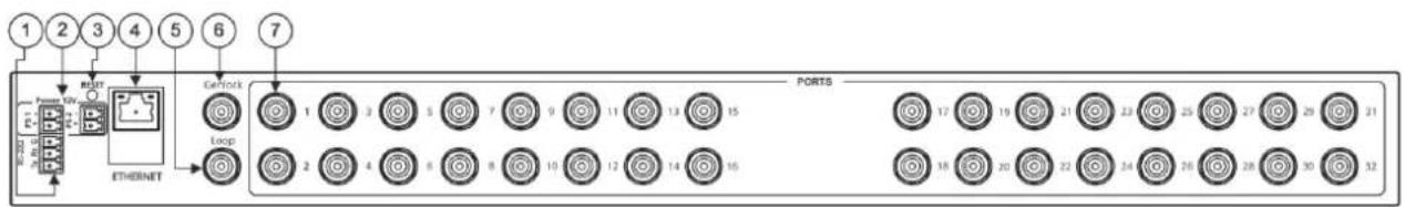
Figure 1: ASPEN-32UFX 12G SDI Matrix Switcher Back Panel
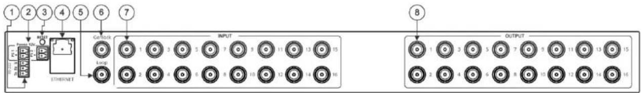
Figure 2: ASPEN-1616UX 12G SDI Matrix Switcher Back Panel
| # | Feature | Function |
| 1 | RS-232 (G,Rx,Tx) Terminal Block Connector | Connect to a PC or remote controller. |
| 2 | POWER 12V DC Terminal Block Connector | Dual power supply for redundancy:PS 1 – primary power connectorPS 2 – redundant power connector (optional).Connect each power adapter into a separate branch circuit employing a separate service ground. |
| 3 | RESET Button | Press briefly to restart the system.Press for 5 seconds to reset all settings, including IP settings to factory default values. |
| 4 | ETHERNET RJ-45 Connector | Connect to a PC via LAN for unit control and firmware upgrade via the web pages. |
| 5 | LOOP BNC Connector | Connect to the genlock connector of the next unit in the daisy chain or terminate with 75Ω. |
| 6 | GENLOCK BNC Connector | Connect to a genlock source. |
| 7 | ASPEN-32UFXPORTS BNC Connectors (1 to 32) | Connect to SDI sources and acceptors. |
| ASPEN-1616UX:INPUT BNC Connectors (1 to 16) | Connect to SDI sources. | |
| 8 | ASPEN-1616UX:OUTPUT BNC Connectors(1 to 16) | Connect to SDI acceptors. |
flowchart
graph TD
    A["1"] --> B["POWER"]
    B --> C["PORTS"]
    C --> D["TIME"]
    D --> E["CLAM"]
    E --> F["LOAD"]
    F --> G["SAVE"]
    G --> H["INFO"]
    H --> I["Control Panel"]
    I --> J["8"]
    J --> K["LACK"]
    K --> L["9"]
    style A fill:#f9f,stroke:#333
    style L fill:#ccf,stroke:#333
    note right of A: POWER
    note left of C: Programmable 8 port 12G SDI Router
    note right of F: Programmable 8 port 12G SDI Router
    note right of H: Programmable 8 port 12G SDI Router
    note right of I: Programmable 8 port 12G SDI Router
    note right of J: Programmable 8 port 12G SDI Router
    note right of K: Programmable 8 port 12G SDI Router
    note right of L: Programmable 8 port 12G SDI Router
    note_right_of_M["Power Supply"]
    note_right_of_N["Load Supply"]
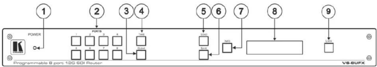
Figure 3: VS-8UFX 12G SDI Matrix Switcher Front Panel
| # | Feature | Function |
| 1 | POWER LED | Lights when the device is powered. |
| 2 | PORT Buttons (1 to 8) | Press an output port (lit green) and then an input port (lit blue) to route an input to an output. |
| 3 | CLEAR Button | Press to clear a selection. |
| 4 | TAKE Button | Press to enter Take mode.In Take mode, press several sets of output-input ports and then press TAKE to activate all the selected routings at the same time.When Take mode is off, each output-input pair is switched immediately. |
| 5 | LOAD Button | To load a preset configuration:Press LOAD, press the appropriate PORT preset button to select a preset configuration, and then press TAKE to load that preset. |
| 6 | SAVE Button | To save the current port configuration to a PORT preset button:Press SAVE, press the port button to which you want to save the configuration, and then press TAKE to save the setup to that port. |
| 7 | INFO Button | Press to display general information, such as the firmware version and IP address.Press INFO and then a specific PORT button to display the information of that selected port. |
| 8 | LCD Display Panel | Displays the current routing status, device information and so on. |
| 9 | LOCK Button | Press for 3 seconds (approx.) to lock the front panel buttons.When locked (button is lit), press again for 3 seconds (approx.) to unlock the front panel buttons. |
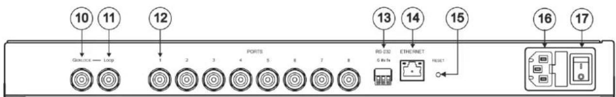
Figure 4: VS-8UFX 12G SDI Matrix Switcher Back Panel
| # | Feature | Function |
| 10 | GENLOCK BNC Connector | Connect a the genlock source. |
| 11 | LOOP BNC Connector | Connect to the genlock connector of the next unit in the daisy chain or terminate with 75Ω. |
| 12 | PORTS BNC Connectors (1 to 8) | Connect to SDI sources and acceptors. |
| 13 | RS-232 (G,Rx,Tx) Terminal Block Connector | Connect to a PC or remote controller. |
| 14 | ETHERNET RJ-45 Connector | Connect to a PC via LAN for unit control and firmware upgrade via the web pages. |
| 15 | RESET Button | Press briefly to restart the system.Press for 10 seconds to reset IP settings to factory default values.The device powers up and loads the factory default values:IP address: 192.168.1.39; Mask: 255.255.0.0; Gateway 192.168.0.1. |
| 16 | Power Socket | Connect to AC power source. |
| 17 | Power Switch | Switch for turning the unit ON and OFF. |
Installing in a Rack
This section provides instructions for rack mounting ASPEN-32UFX, ASPEN-1616UX, VS-8UFX. Before installing in a rack, verify that the environment is within the recommended range:
• Operation temperature – 0° to 40°C (32 to 104°F).
- Storage temperature -40^ to +70^ (-40 to +158^ ).
- Humidity – 10% to 90%, RHL non-condensing.

When installing on a 19" rack, avoid hazards by taking care that:
- It is located within recommended environmental conditions. Operating ambient temperature of a closed or multi-unit rack assembly may exceed ambient room temperature.
- Once rack mounted, there is enough air flow around ASPEN-32UFX, ASPEN-1616UX, VS-8UFX.
- ASPEN-32UFX, ASPEN-1616UX, VS-8UFX is placed upright in the correct horizontal position.
- You do not overload the circuit(s). When connecting VS-8UFX to the supply circuit, overloading the circuits may have a detrimental effect on overcurrent protection and supply wiring. Refer to the appropriate nameplate ratings for information. For example, for fuse replacement, see the value printed on the product label.
- VS-8UFX is earthed (grounded) and connected only to an electricity socket with grounding. Pay particular attention when electricity is supplied indirectly (for example, when the power cord is not plugged directly into the wall socket but to an extension cable or power strip). Use only the supplied power cord.
To rack-mount ASPEN-32UFX, ASPEN-1616UX, VS-8UFX:
- Remove the three screws from each side of the unit, reinsert those screws through the rack ears and mount on a 19" rack.

- Detachable rack ears can be removed for desktop use.
- Always mount ASPEN-32UFX, ASPEN-1616UX, VS-8UFX in the rack before connecting any cables or power.
Connecting ASPEN-32UFX, ASPEN-1616UX, VS-8UFX

Always switch off the power to each device before connecting it to your ASPEN-32UFX, ASPEN-1616UX, VS-8UFX. After connecting your ASPEN-32UFX, ASPEN-1616UX, VS-8UFX, connect its power and then switch on the power to each device.
Connecting ASPEN 32UFX, ASPEN 1616UX

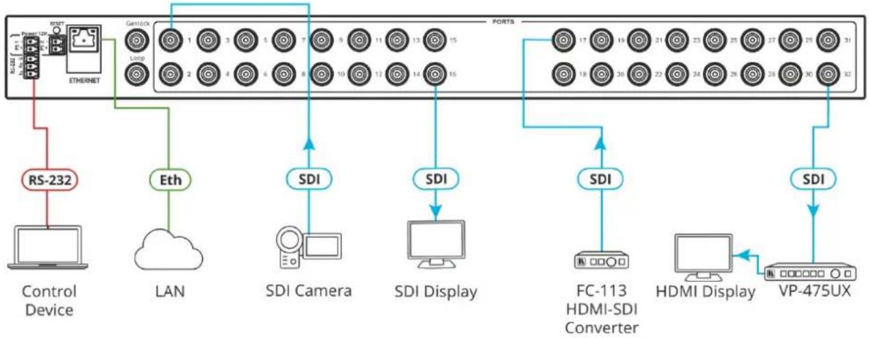
For illustrative purposes, the figure below shows ASPEN 32UFX, but the same connections apply to ASPEN 1616UX. The only exception is that for ASPEN 32UFX the sources and acceptors can be connected to any of the 32 interchangeable ports and for ASPEN 1616UX the sources must be connected to the inputs and the acceptors to the outputs.
flowchart
graph TD
    A["Control Device"] -->|RS-232| B["Ethernet"]
    B --> C["GenioX"]
    C --> D["1 3 5 7 9 11 13 15"]
    D --> E["SDI Camera"]
    E --> F["SDI Display"]
    F --> G["FC-113 HDMI-SDI Converter"]
    G --> H["HDMI Display"]
    H --> I["VP-475UX"]
    C --> J["SDI"]
    J --> K["SDI Display"]
    K --> L["FC-113 HDMI-SDI Converter"]
    L --> M["HDMI Display"]
    M --> N["VP-475UX"]
Figure 5: Connecting to the ASPEN-32UFX Rear Panel
To connect ASPEN 32UFX or ASPEN 1616UX as illustrated in Figure 5:
-
Connect the video sources (for example, SDI camera, FC-113 HDMI™-SDI Converter) and acceptors (for example, SDI display, VP-475UX SDI to HDMI converter):
-
For ASPEN-32UFX connect up to 32 video sources and acceptors to the interchangeable PORT BNC Connectors ⑦
-
For ASPEN 1616UX connect up to 16 video sources to the INPUT BNC Connectors and up to 16 video acceptors to the OUTPUT BNC Connectors . ⑧
-
Connect the LAN to the ETHERNET RJ-45 Connector ④
- Connect a control device (for example, computer or serial controller) to the RS-232 Terminal Block Connector ①
-
If required, connect a genlock source to the GENLOCK BNC Connector ⑥
-
Connect the next SDI switcher in a daisy chain to the LOOP BNC Connector ⑤ -OR- terminate the connector with 75
-
Connect the 12V power adapter to the POWER 12V DC PS1 Terminal Block Connector ②
-
Optionally, connect a second 12V power adapter to the POWER 12V DC PS2 Terminal Block Connector as a redundant power source.
Connecting VS-8UFX
flowchart
graph LR
    A["Genlock — Loop"] --> B["1"]
    A --> C["2"]
    A --> D["3"]
    A --> E["4"]
    A --> F["5"]
    A --> G["6"]
    A --> H["7"]
    A --> I["8"]
    B --> J["SDI Camera"]
    C --> K["FC-113 HDMI-SDI Converter"]
    D --> L["SDI Display"]
    E --> M["SDI Display"]
    F --> N["SDI Display"]
    G --> O["RS-232 Ethernet RESET"]
    H --> P["Control Device"]
    I --> Q["Eth"]
    L --> R["SDI Display"]
    M --> S["DSI Display"]
    N --> T["DSI Display"]
    O --> U["DSI Display"]
    P --> V["DSI Display"]
    Q --> W["DSI Display"]
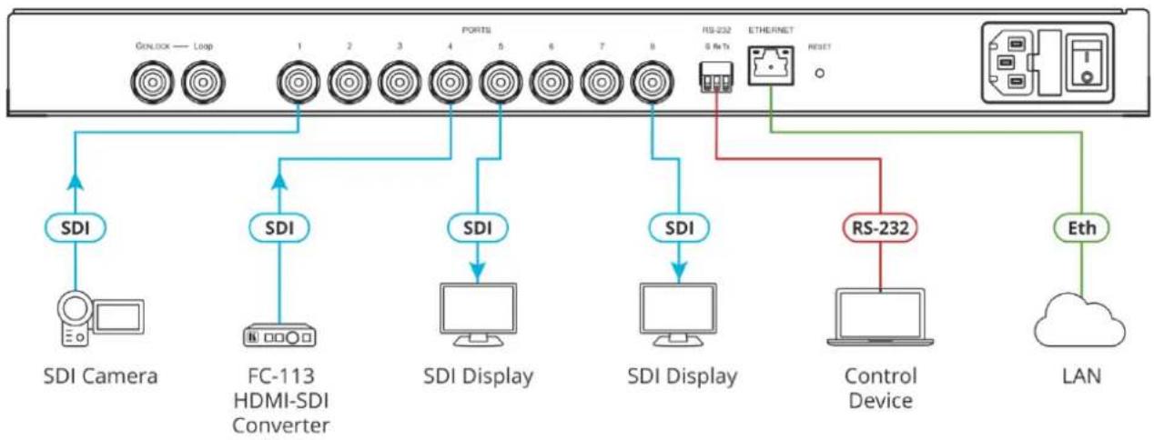
Figure 6: Connecting to the VS-8UFX Rear Panel
To connect VS-8UFX as illustrated in Figure 6:
-
Connect up to 8 video sources (for example, SDI camera, FC-113 HDMI™-SDI Converter) and acceptors (for example, SDI display, VP-475UX SDI to HDMI converter) to the interchangeable PORTS BNC Connectors ^12
-
Connect the LAN to the ETHERNET RJ-45 Connector ①4
-
Connect a control device (for example, computer or serial controller) to the RS-232 Terminal Block Connector ⑬
-
If required, connect a genlock source to the GENLOCK BNC Connector ⑩.
-
If required, connect the next SDI switcher in a daisy chain to the LOOP BNC Connector ⑪
-OR- terminate the connector with 75Ω.
- Connect the power cord to the Power Socket ⑯.
Configuring ASPEN-32UFX, ASPEN-1616UX, VS-8UFX
ASPEN-32UFX, ASPEN-1616UX, VS-8UFX enable you to configure settings in the following ways:
- Via Ethernet using built-in, user-friendly web pages (see Configuring – Web Pages on page 10).
- Protocol 3000 commands (see Protocol 3000 Commands on page 34).
In addition, VS 8UFX can be operated from its front panel buttons (see Configuring – Front Panel on page 20).
Configuring – Web Pages
The embedded web pages enable you to configure ASPEN-32UFX, ASPEN-1616UX, VS-8UFX via Ethernet.

For illustrative purposes, the screenshots below show the web pages of only one of the 3 devices – the web pages of your device may differ in the number and type of ports it shows and in some of the features. Unless otherwise noted, the instructions apply to all devices.
ASPEN-32UFX, ASPEN-1616UX, VS-8UFX web pages enable performing the following:
• Defining Interchangeable Ports on page 12.
- Saving Configuration – Web Page on page 14.
- Configuring Genlock Settings on page 16.
- Configuring Network Settings on page 16.
• Changing the TCP Port on page 17.
• Changing the Unit Name on page 17.
• Enabling/Disabling Web Page Password Security on page 18.
• Changing Web Pages Password on page 18.
• Upgrading the Firmware on page 19.
To browse ASPEN-32UFX, ASPEN-1616UX, VS-8UFX web pages:
- Type the IP address of the device in the address bar of your internet browser (default = 192.168.1.39).
The Login page window appears.
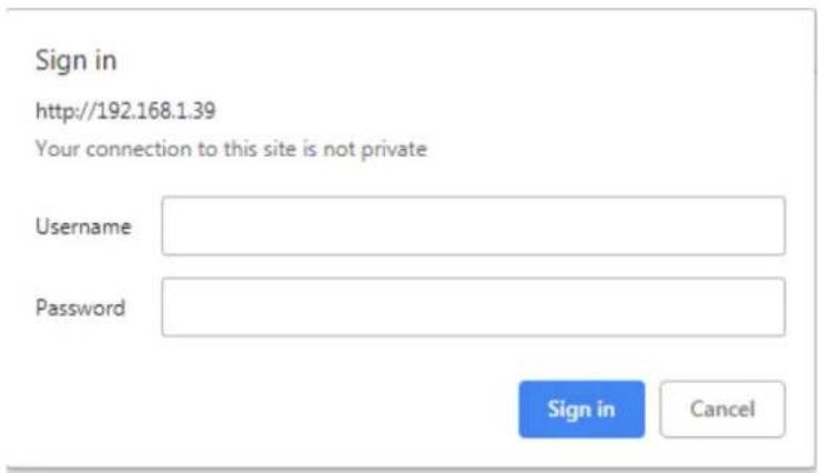
Figure 7: Embedded Web Pages Login Window
- Enter the Username (default = Admin) and Password (default = Admin) and click Sign in.
The embedded web pages appear with the Video Switching page open.
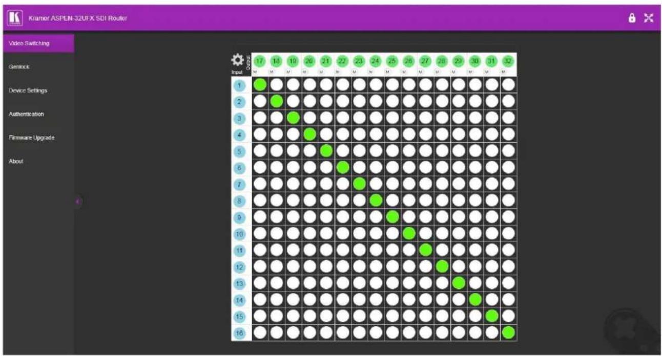
Figure 8: Embedded Web Pages with Video Switching Page Open
- Use the navigation pane on the left to open the desired web page.
Defining Interchangeable Ports

This section applies only to ASPEN-32UFX and VS-8UFX.
The embedded web pages enable you to define each interchangeable port on ASPEN-32UFX and VS-8UFX as an input or an output. The procedure for defining the ports is slightly different for each of the models, as follows:
• Defining ASPEN-32UFX Ports on page 12.
• Defining VS-8UFX Ports on page 14.
Defining ASPEN-32UFX Ports
To define ASPEN-32UFX interchangeable ports:
1. Click Video Switching.
The Video Switching page appears.
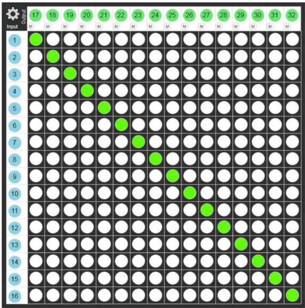
Figure 9: ASPEN-32UFX Embedded Web Pages – Video Switching Page
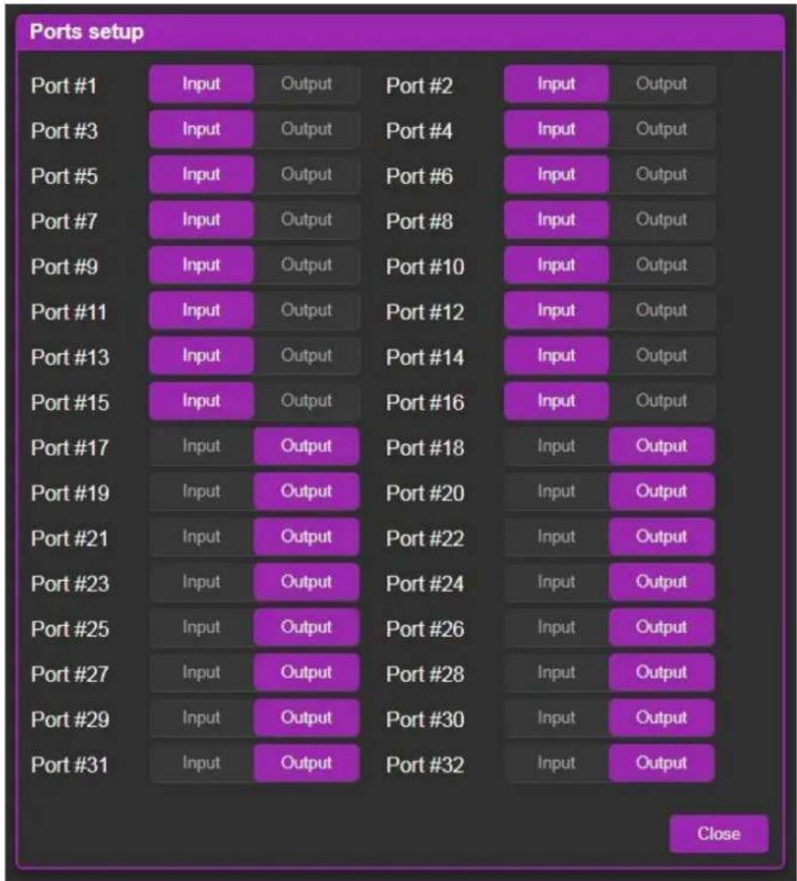
- Click the Settings icon in the upper left corner.
The Ports setup page appears.
heatmap
Ports setup | Port #1 | Input | Output | Port #2 | Input | Output | |---|---|---|---|---|---| | Port #3 | Input | Output | Port #4 | Input | Output | | Port #5 | Input | Output | Port #6 | Input | Output | | Port #7 | Input | Output | Port #8 | Input | Output | | Port #9 | Input | Output | Port #10 | Input | Output | | Port #11 | Input | Output | Port #12 | Input | Output | | Port #13 | Input | Output | Port #14 | Input | Output | | Port #15 | Input | Output | Port #16 | Input | Output | | Port #17 | Input | Output | Port #18 | Input | Output | | Port #19 | Input | Output | Port #20 | Input | Output | | Port #21 | Input | Output | Port #22 | Input | Output | | Port #23 | Input | Output | Port #24 | Input | Output | | Port #25 | Input | Output | Port #26 | Input | Output | | Port #27 | Input | Output | Port #28 | Input | Output | | Port #29 | Input | Output | Port #30 | Input | Output | | Port #31 | Input | Output | Port #32 | Input | Output | CloseFigure 10: ASPEN-32UFX Embedded Web Pages – Video Switching > Ports Setup Page
-
For each port, click Input or Output.
The port changes to the selected mode. -
When you are finished defining ports, click Close. The Video Switching page appears.
Defining VS-8UFX Ports
To define VS-8UFX interchangeable ports:
1. Click Video Switching.
The Video Switching page appears.
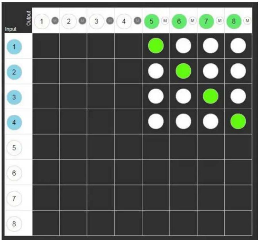
Figure 11: VS-8UFX Embedded Web Pages – Video Switching Page
-
Click a white number in the left column to define that port as an input. The selected port turns blue and the port changes to an input.
-
Click a white number in the upper row to define that port as an output. The selected port turns green and the port changes to an output.
Saving Configuration – Web Page
The embedded web pages enable you to save the input/output definitions (for ASPEN-32UFX and VS-8UFX) and switching configuration as a preset for recall at a later time.
To save a configuration as a preset:
-
Define each port as an input or output (for ASPEN-32UFX and VS-8UFX – see Defining Interchangeable Ports on page 12).
-
Switch inputs to outputs (see Switching – Web Pages on page 21).
-
Click Device Settings.
The Device Settings page appears.
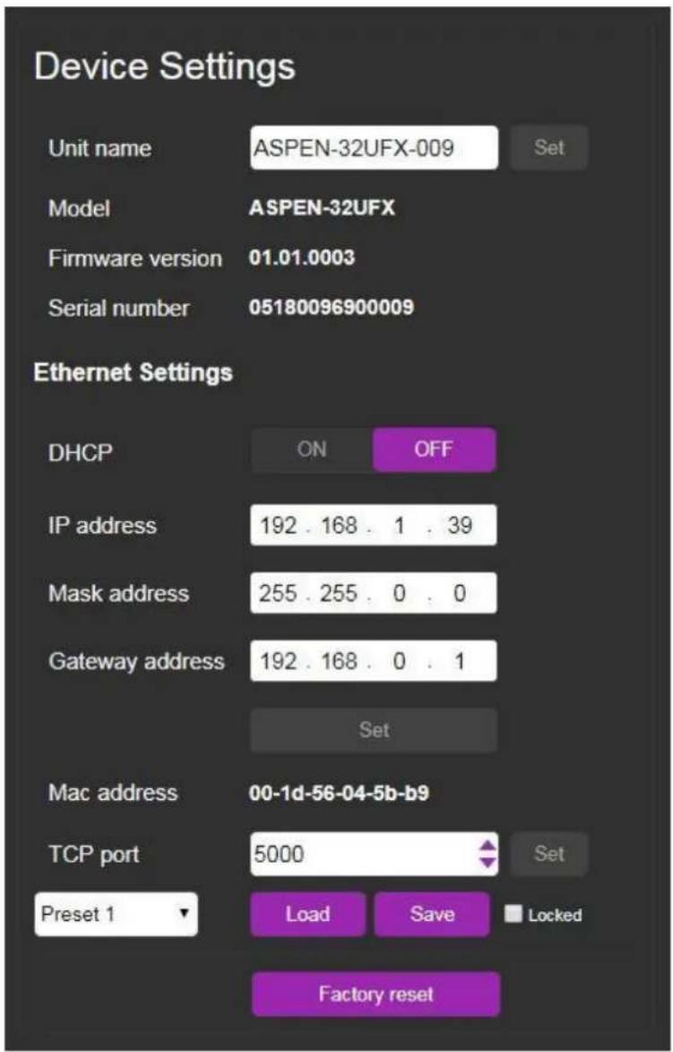
Figure 12: Embedded Web Pages – Device Settings Page
- From the Preset 1 drop-down, select the preset number to which you would like to save this configuration.
- Click Save.
The current input/output definitions (for ASPEN-32UFX and VS-8UFX) and switching configuration are saved under the selected preset number.

Clicking the Save button overwrites the configuration that was previously saved under the selected preset number.
Disable the Save button for the selected Preset to prevent losing the currently saved configuration by selecting the Locked checkbox.

To load a saved configuration, see Loading Saved Configurations – Web Pages on page 22.
Configuring Genlock Settings
The embedded web pages enable you to configure genlock settings for when you connect a Genlock source to your device.
To configure genlock settings:
1. Click Genlock.
The Genlock page appears.
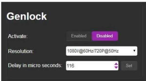
Figure 13: Embedded Web Pages – Genlock Page
- Click Enabled.
Genlock is enabled.
- In the Resolution drop-down, select the display resolution.
The preset delay for that resolution appears under Delay in micro seconds.

It is recommended to use one of the preset delay times, according to the resolution. If required you can set a custom delay in the Delay in micro seconds field, and click Set.
Configuring Network Settings
The embedded web pages enable you to configure network settings for your device.

For proper settings and before changing to DHCP, consult your network administrator.
To configure network settings:
- Click Device Settings.
The Device Settings page appears (Figure 12).
- In the Ethernet Settings section, change the network settings as required and click Set.
-OR-
If you want the device to obtain a DHCP IP, under DHCP, click ON.
- Click Set.
A warning appears.
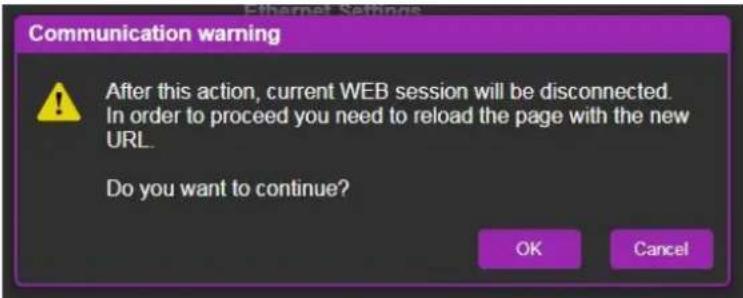
Figure 14: Network Settings Warning
4. Click OK.
The network settings change and a confirmation appears.
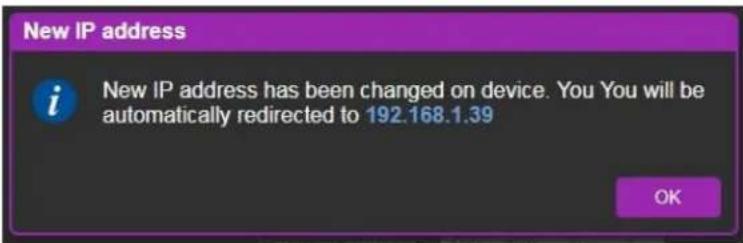
Figure 15: Network Settings Confirmation
5. Click OK.
The web page logs out and the browser reloads with the new network information.
Changing the TCP Port
To change the device TCP port.
- Click Device Settings.
The Device Settings page appears (Figure 12).
- In the Ethernet Settings section, under TCP port, change the number as required and click Set.
The new TCP port number is saved.
Changing the Unit Name
To change the unit name:
- Click Device Settings.
The Device Settings page appears (Figure 12).
- Enter the new name of the unit in the Unit Name text box.
The unit name cannot include any spaces, can be up to 63 characters and can include only letters, numbers, hyphens and underscores.
- Click Set.
The unit name is changed.

The first 15 characters of the unit name are used by the NetBIOS protocol.
Enabling/Disabling Web Page Password Security
The embedded web pages enable you to require a password for logging into the web pages or to disable this feature and allow login without a password.
To enable/disable web page security:
1. Click Authentication.
The Authentication page appears.
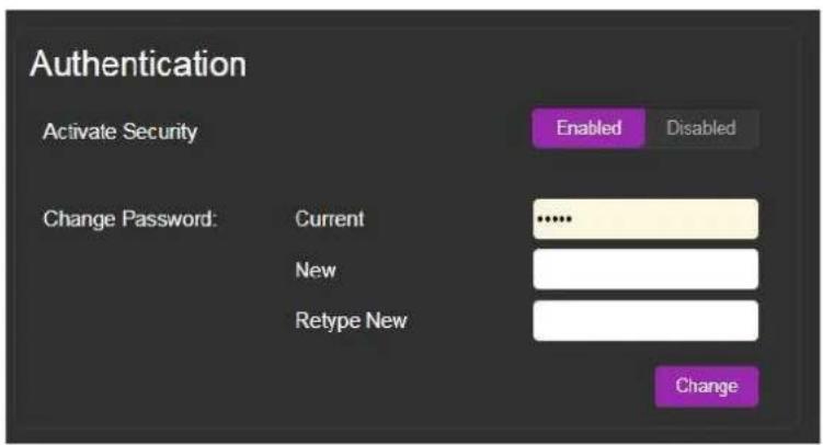
Figure 16: Embedded Web Pages – Authentication Page
2. Click Enabled/Disabled.
Web page security is enabled/disabled.
Changing Web Pages Password
To change the web pages password when security is enabled:
1. Click Authentication.
The Authentication page appears (Figure 16).
Enter the current password, new password and retype the new password.

A password must contain 5 to 15 alphanumeric characters and no spaces.
2. Click Change.
A warning appears.
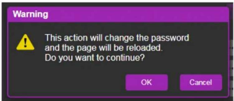
Figure 17: Password Change Warning
3. Click OK.
The password is changed, and the login window appears (Figure 7).
- Log in with the new password.
A message appears.
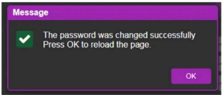
Figure 18: Password Change Success Message
- Click OK.
The web pages reload.
Upgrading the Firmware
To upgrade the device firmware:
- Click Firmware Upgrade.
The Firmware Upgrade page appears.
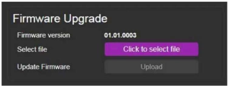
Figure 19: Firmware Upgrade Page
- Click Click to select file.
A file browser appears.
-
Open the relevant firmware file.
-
Click Upload.
The firmware uploads to the device.

Caution: Do not power cycle or operate the device during firmware upgrade.
Configuring – Front Panel

This section applies only to VS 8UFX.
VS 8UFX enables you to configure the device using the front panel buttons and LCD display.
Saving Configuration – Front Panel
VS 8UFX front panel buttons enable you to save the input/output definitions and switching configuration as a preset for later recall.
To save a configuration as a preset:
- Define each port as an input or output (see Defining Interchangeable Ports on page 12).

The ports can be defined as an input or output only from the web pages.
-
Switch inputs to outputs (see Switching - Front Panel on page 23).
-
Press the SAVE Button 6 The SAVE Button lights and the PORT Button lights go off.
-
Press the PORT Button ☐ to which you would like to save the configuration. The PORT Button flashes red.
-
Press the TAKE button ④ The PORT and TAKE Buttons return to their previous state and the current configuration is saved under the selected PORT Button.

Saving a configuration overwrites the configuration that was previously saved under the selected PORT Button.
To disable the Save button to prevent losing a previous configuration see Saving Configuration – Web Page on page 14.
Verifying Device Information
The VS 8UFX front panel enables you to view the device firmware version and IP address.
To view device information:
- Press the INFO Button .⑦ The device firmware version and IP address appear on the LCD Display Panel ⑧
Operating ASPEN-32UFX, ASPEN-1616UX, VS-8UFX
Operate your ASPEN-32UFX, ASPEN-1616UX, VS-8UFX using any of the following methods:
- Via Ethernet using built-in, user-friendly web pages (see Operating – Web Pages on page 21).
- Protocol 3000 commands (see Protocol 3000 Commands on page 34).
In addition, VS 8UFX can be operated from its front panel buttons (see Operating – Front Panel Buttons on page 23).
Operating – Web Pages
ASPEN-32UFX, ASPEN-1616UX, VS-8UFX web pages enable performing the following:
- Switching – Web Pages on page 21.
• Muting Outputs on page 22. - Loading Saved Configurations – Web Pages on page 22.
Switching – Web Pages
The embedded web pages enable you to switch inputs to outputs. One input can be switched to multiple outputs, but each output can only have one input switched to it.

For instructions to define whether a port is an input or output, see (see Defining Interchangeable Ports on page 12).

The screenshots are for demonstration purposes and may differ for your device.
To switch input 1 to output 21:
- Click Video Switching. The Video Switching page appears (Figure 9).
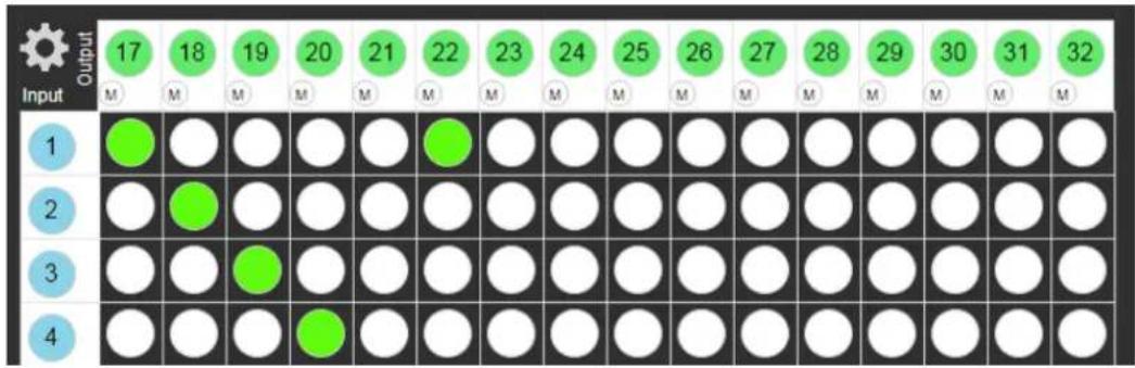
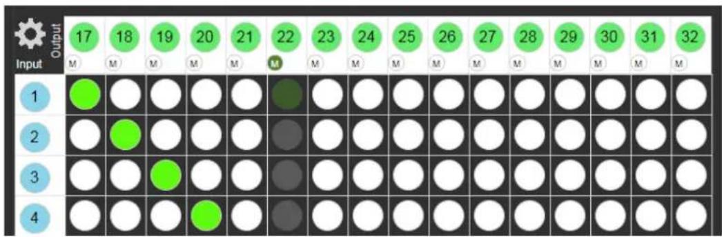
- Click the circle in the switching table that corresponds to the input row and output column that you want to switch. For example, in the switching table below, click the first circle in the column for output 22.
The circle turns green, and Input 1 is switched to output 22.
other
| Input \ Output | 17 | 18 | 19 | 20 | 21 | 22 | 23 | 24 | 25 | 26 | 27 | 28 | 29 | 30 | 31 | 32 | |---|---|---|---|---|---|---|---|---|---|---|---|---|---|---|---|---| | M | M | M | M | M | M | M | M | M | M | M | M | M | M | M | M | M | | 1 | Green | White | White | White | White | Green | White | White | White | White | White | White | White | White | White | White | | 2 | White | Green | White | White | White | White | White | White | White | White | White | White | White | White | White | White | | 3 | White | White | Green | White | White | White | White | White | White | White | White | White | White | White | White | White | | 4 | White | White | White | Green | White | White | White | White | White | White | White | White | White | White | White | White |Figure 20: Input 1 Switched to Output 22
Muting Outputs
The embedded web pages enable you to disable (mute) the video and audio of each output individually.
To mute an output:
- Click Video Switching.
The Video Switching page appears (Figure 9).
- Click the M at the top of the column of the output to be muted.
The column is grayed out and the output is muted.

A muted output shows no signal on the display.

You can switch an input to a muted output.
other
| Input\Output | 17 | 18 | 19 | 20 | 21 | 22 | 23 | 24 | 25 | 26 | 27 | 28 | 29 | 30 | 31 | 32 | |---|---|---|---|---|---|---|---|---|---|---|---|---|---|---|---|---| | 1 | ● | ○ | ○ | ○ | ○ | ● | ○ | ○ | ○ | ○ | ○ | ○ | ○ | ○ | ○ | ○ | | 2 | ○ | ● | ○ | ○ | ○ | ● | ○ | ○ | ○ | ○ | ○ | ○ | ○ | ○ | ○ | ○ | | 3 | ○ | ○ | ● | ○ | ○ | ● | ○ | ○ | ○ | ○ | ○ | ○ | ○ | ○ | ○ | ○ | | 4 | ○ | ○ | ○ | ● | ○ | ● | ○ | ○ | ○ | ○ | ○ | ○ | ○ | ○ | ○ | ○ |Figure 21: Output 22 Muted
Loading Saved Configurations - Web Pages
The embedded web pages enable you to load preset input/output definitions (for ASPEN-32UFX and VS-8UFX) and switching configurations.

To save a configuration, see Saving Configuration – Web Page on page 14.
To load a saved configuration:
- Click Device Settings.
The Device Settings page appears (Figure 12).
-
Select the relevant Preset number from the Preset 1 drop-down.
-
Click Load.
The input/output definitions (for ASPEN-32UFX and VS-8UFX) and switching configuration changes according to the preset, and a message appears.
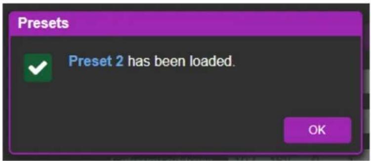
Figure 22: Preset Loaded Message
- Click OK to return the web pages.
Operating - Front Panel Buttons

This section applies only to VS 8UFX.
Switching - Front Panel
VS 8UFX front panel buttons enable you to switch an input to an output in the following ways:
- Direct Switching – Activate a switching event immediately after pressing the buttons (see page 23).
- Take Mode Switching – Program multiple switching events and execute them simultaneously (see page 24).

For instructions to define whether a port is an input or output, see (see Defining Interchangeable Ports on page 12).
Direct Switching
To switch an input to an output directly:
- Press the required green output PORT Button ② The selected button flashes.

If an input button is not pressed within about 10 sec, the switching operation is cancelled, and the button goes back to its original state.
- Press the required blue input PORT Buttons ②
The selected input is switched to the selected output and the change is reflected in the LCD display.
Take Mode Switching
To execute multiple switching events, simultaneously:
- Press the TAKE Button ④
The TAKE Button flashes and the panel enters Take Mode. - Press a green output PORT Button and a blue input PORT Buttons . ②
The switching event appears on the LCD display. - Press additional input/output pairs.
The switching events appear on the LCD display. - Press the TAKE Button ④
All of the selected switching events are executed.
Loading Saved Configurations - Front Panel
VS 8UFX front panel buttons enable you to load preset input/output definitions and switching configurations.

To save a configuration, see Saving Configuration – Front Panel on page 20.
To load a saved configuration:
- Click the LOAD Button .5
The LOAD Button flashes and PORTS Buttons lights go off. - Click the PORTS Button that corresponds to the preset number under which the configuration is saved.
The selected PORTS Button flashes red and the preset configuration appears on the LCD display. - Click the TAKE Button ④
The configuration is loaded and the PORTS Buttons light normally.
Technical Specifications
| ASPEN-32UFX | Inputs | 1 Genlock | On a BNC connector |
| Outputs | 1 Genlock (Loop) | On a BNC connector | |
| Ports | 32 Interchangeable12G SDI/HD-SDI/SDI Video (75Ω) | On BNC connectors (by default, 1 to 16 are set as inputs and 17 to 32 are set as outputs) | |
| 1 RS-232 | On a 3-pin terminal block | ||
| 1 Ethernet | On an RJ-45 connector | ||
| 1 12V DC Primary Power | On a 2-pin connector | ||
| 1 12V DC Redundant Power | On a 2-pin connector | ||
| ASPEN-1616UX | Inputs | 16 12G SDI/HD-SDI/SDI Video (75Ω) | On BNC connectors |
| 1 Genlock | On a BNC connector | ||
| Outputs | 16 12G SDI/HD-SDI/SDI Video (75Ω) | On BNC connectors | |
| 1 Genlock (Loop) | On a BNC connector | ||
| Ports | 1 RS-232 | On a 3-pin terminal block | |
| 1 Ethernet | On an RJ-45 connector | ||
| 1 12V DC Primary Power | On a 2-pin connector | ||
| 1 12V DC Redundant Power | On a 2-pin connector | ||
| VS-8UFX | Inputs | 1 Genlock | On a BNC connector |
| Outputs | 1 Genlock (Loop) | On a BNC connector | |
| Ports | 8 Interchangeable12G SDI/HD-SDI/SDI Video (75Ω) | On BNC connectors (by default, 1 to 4 are set as inputs and 5 to 8 are set as outputs) | |
| 1 RS-232 | On a 3-pin terminal block | ||
| 1 Ethernet | On an RJ-45 connector | ||
| 1 AC Power | On an AC power connector | ||
| Video | Standards: | 12G-SDI - SMPTE ST-2082-13G-SDI - SMPTE 424M6G - SMPTE ST-2081HD-SDI - SMPTE 292MSDI - SMPTE 259M/344M | |
| Max Resolution | 4K@60Hz (4:2:2) | ||
| Max Bandwidth | 12Gbps | ||
| Extension Line | SD Signals | Up to 300m | |
| 1.5G HD Signals | Up to 200m | ||
| 3G Signals | Up to 100m | ||
| 6G Signals | Up to 100m | ||
| 12G Signals | Up to 80m | ||
| Coupling | DC | ||
| User Interface (ASPEN-32UFX, ASPEN-1616UX) | Controls | Web pages and Protocol 3000 API via Ethernet and remote RS-232 | |
| User Interface (VS-8UFX) | Indicators | Port buttons LEDs, LCD display | |
| Controls | Switching buttons, web pages and Protocol 3000 API via Ethernet and remote RS-232 | ||
| Supported Web Browsers | Windows 7 | Internet Explorer, Firefox, Chrome, Safari | |
| Windows 10 | Internet Explorer, Edge, Firefox, Chrome | ||
| MAC 10.11 | Safari | ||
| iOS 10.3.2 | Safari | ||
| Android | N/A | ||
| Power (ASPEN-32UFX) | Consumption | 12V DC, 2A | |
| Source | 5A | ||
| Power (ASPEN-1616UX) | Consumption | 12V DC, 1.35A | |
| Source | 5A | ||
| Power (VS-8UX) | Consumption | 100–240V AC | |
| Source | 33VA max | ||
| Enclosure | Size | 19" 1U | |
| Type | Aluminum | ||
| Cooling | Fan Ventilation | ||
| Regulatory Compliance | Safety | CE | |
| Environmental | RoHs, WEEE | ||
| ASPEN-32UFX, ASPEN-1616UX | Dimensions and Weight | Net Dimensions (W, D, H) | 43.64cm x 10.00cm x 4.36cm (17.18" x 3.94" x 1.72") |
| Net Weight | 1.0kg (2.1lbs) approx. | ||
| Shipping Dimensions (W, D, H) | 55.00cm x 27.60cm x 10.70cm (21.65" x 10.87" x 4.21") | ||
| Shipping Weight | 1.9kg (4.1lbs) approx. | ||
| VS-8UFX | Dimensions and Weight | Net Dimensions (W, D, H) | 43.64cm x 18.30cm x 4.36cm (17.18" x 7.20" x 1.72") |
| Net Weight | 1.7kg (3.7lbs) approx. | ||
| Shipping Dimensions (W, D, H) | 55.00cm x 27.60cm x 10.70cm (21.65" x 10.87" x 4.21") | ||
| Shipping Weight | 2.7kg (6.0lbs) approx. | ||
| Accessories | Included | Power adapter/ cord, rack ears | |
| Optional | For optimum range and performance use the recommended Kramer cables available at www.kramerav.com/product/ASP EN-32UFX | ||
| Specifications are subject to change without notice at www.kramerav.com | |||
Default Communication Parameters
| RS-232 / Protocol 3000 | |
| Baud Rate: | 115,200 |
| Data Bits: | 8 |
| Stop Bits: | 1 |
| Parity: | None |
| Command Format: | ASCII |
| Command Example: | Route INPUT 1 to OUTPUT 5:#X-ROUTE OUT.SDI.5.VIDEO.1,IN.SDI.1.VIDEO.1 |
| Ethernet | |
| IP Address: | 192.168.1.39 |
| Subnet mask: | 255.255.0.0 |
| Default gateway: | 192.168.0.1 |
| TCP Port #: | 5000 |
| Maximum TCP Ports: | 1 |
Resetting the Unit
Two types of reset can be performed:
- Reboot – Reboots your unit and keeps all your unit settings, including the IP address and password.
- Factory reset – Reboots your unit and restores all factory settings including input/output definitions, switching configuration, IP address and password.
Resetting the device can be accomplished by using:
- The Front Panel Reset button.
- Protocol 3000 commands (see System Commands on page 34).
- Web pages

The device must be powered ON when performing a reset.
To reset a device using the back panel:
- Press the RESET Button with the tip of a paper clip:
■ For reboot, press and release.
- For factory reset, press and hold for more than 5 seconds.
To perform a factory reset on the device using the web pages:
-
Click Device Settings.
The Device Settings page appears (Figure 12). -
Click Factory reset.
Protocol 3000
The ASPEN-32UFX, ASPEN-1616UX, VS-8UFX 12G SDI Matrix Switcher can be operated using the Kramer Protocol 3000 serial commands. The command framing varies according to how you interface with the ASPEN-32UFX, ASPEN-1616UX, VS-8UFX.
Generally, a basic video input switching command that routes a layer 1 video signal to HDMI out 1 from HDMI input 2 (ROUTE 1,1,2), is entered as follows:
• Terminal communication software, such as Hercules:
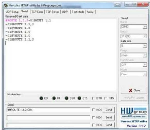

The framing of the command varies according to the terminal communication software.
• K-Touch Builder (Kramer software):
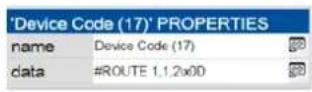
• K-Config (Kramer configuration software):
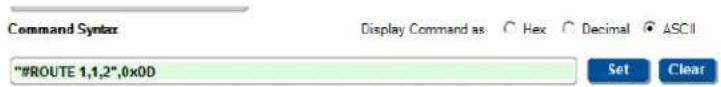

All the examples provided in this section are based on using the K-Config software.
You can enter commands directly using terminal communication software (e.g., Hercules) by connecting a PC to the serial or Ethernet port on the ASPEN-32UFX, ASPEN-1616UX, VS-8UFX. To enter press the Enter key ( is also sent but is ignored by the command parser).
Commands sent from various non-Kramer controllers (e.g., Crestron) may require special coding for some characters (such as, /X##). For more information, refer to your controller's documentation.
For more information about Protocol 3000 commands, see:
• Understanding Protocol 3000 on page 30.
• Kramer Protocol 3000 Syntax on page 30.
• Protocol 3000 Commands on page 34.
Understanding Protocol 3000
Protocol 3000 commands are structured according to the following:
- Command – A sequence of ASCII letters (A–Z, a–z and -). A command and its parameters must be separated by at least one space.
- Parameters – A sequence of alphanumeric ASCII characters (0–9, A–Z, a–z and some special characters for specific commands). Parameters are separated by commas.
- Message string – Every command entered as part of a message string begins with a message starting character and ends with a message closing character.

A string can contain more than one command. Commands are separated by a pipe (1) character.
- Message starting character:
– For host command/query
\~ – For device response
• Device address – K-NET Device ID followed by @ (optional, K-NET only)
- Query sign – ? follows some commands to define a query request
- Message closing character: – Carriage return for host messages (ASCII 13) LF – Carriage return for device messages (ASCII 13) and line-feed (ASCII 10)
- Command chain separator character – Multiple commands can be chained in the same string. Each command is delimited by a pipe character (1). When chaining commands, enter the message starting character and the message closing character only at the beginning and end of the string.

Spaces between parameters or command terms are ignored. Commands in the string do not execute until the closing character is entered. A separate response is sent for every command in the chain.
Kramer Protocol 3000 Syntax
The Kramer Protocol 3000 syntax uses the following delimiters:
- CR = Carriage return (ASCII 13 = 0x0D)
• Line feed (ASCII 10 = 0x0A) - sp = Space (ASCII 32 = 0x20)
Some commands have short name syntax in addition to long name syntax to enable faster typing. The response is always in long syntax.
The Protocol 3000 syntax is in the following format:
- Host Message Format:
| Start | Address (optional) | Body | Delimiter |
| # | Device_id@ | Message | c_k |
- Simple Command – Command string with only one command without addressing:
| Start | Body | Delimiter |
| # | Command SPParameter_1,Parameter_2,... |
- Command String – Formal syntax with command concatenation and addressing:
| Start | Address | Body | Delimiter |
| # | Device_id@ | Command_1Parameter1_1,Parameter1_2,...|Command_2Parameter2_1,Parameter2_2,...|Command_3Parameter3_1,Parameter3_2,...|... |
• Device Message Format:
| Start | Address (optional) | Body | Delimiter |
| ~ | Device_id@ | Message |
- Device Long Response – Echoing command:
| Start | Address (optional) | Body | Delimiter |
| ~ | Device_id@ | Command SP [Param1,Param2 ...] result |
Extended Protocol 3000
In addition to the standard Protocol 3000 syntax, newer Kramer products use extended syntax to improve user experience and provide easier deployment and configuration.
For products with many ports and of different types, the extended syntax describes commands and their parameters in a more intuitive, user-friendly format.
To identify devices supporting extended commands, use the #HELP command to list all supported commands. Commands that begin with the prefix 'X-' use extended Protocol 3000 syntax. Extended commands use Port ID (see Port ID Format on page 31) and Signal ID (see Signal ID Format on page 32) instead of the old port naming parameters.
Port ID Format
The port ID is composed of three fields separated by a dot ‘.’
(
Examples:
IN.SDI.1 (refers to SDI input port 1)
OUT.HDMI.4 (refers to HDMI output port 4)
BOTH.RS232.2 (refers to bidirectional RS-232 port 2)
Direction Types
The string representation is not case sensitive.
| String | Meaning |
| IN | Input port |
| OUT | Output port |
| BOTH | Bi-directional port where the direction has no meaning |
Port Types
The string representation is not case sensitive.
| String | Meaning |
| HDMI | HDMI port |
| ANALOG_AUDIO | Any balanced or unbalanced audio ports |
| AMPLIFIED_AUDIO | Any analog outputs defined as amplified audio |
| RS232 | Local control port used for data control |
| IR | Local IR input |
Signal ID Format
The signal ID is composed of three fields separated by a dot ‘.’
(
– Indicates a specific channel number when there are multiple channels of the same type
Signal ID:
also means: <
Examples:
IN.HDMI.1.VIDEO.1 (refers to video channel 1 of HDMI input port 1)
OUT.HDMI.1.AUDIO.1 (refers to audio channel 1 of HDMI output port 1)
Extended Signal Types
The string representation is non-case sensitive.
| String | Meaning |
| VIDEO | Video signal of the port |
| AUDIO | Audio signal of the port |
| RS232 | Data signal of the port (relevant for RS-232 ports for example) |
| IR | IR signal of the port (relevant for IR ports for example; available in future updates) |
Examples
To understand the advantages of the extended Protocol 3000 syntax, compare the standard MUTE and VMUTE command syntax with the extended X-MUTE command syntax.
MUTE and VMUTE are dedicated commands to mute audio and video respectively. Both commands receive the index of the output to mute as a parameter. Two separate commands are used to mute different signal types and neither command enable muting the inputs and not the outputs.
However, the X-MUTE command can mute audio and/or video on either inputs or outputs:
- Mute video on OUT 1: #X-MUTE OUT.HDMI.1.VIDEO.1
- Mute audio on OUT 1: #X-MUTE OUT.HDMI.1.AUDIO.1
- Mute video on HDMI IN 1: #X-MUTE IN.HDMI.1.VIDEO.1
- Mute audio on HDMI IN 1: #X-MUTE IN.HDMI.1.AUDIO.1
The name of the action remains the same and what it affects is passed in parameters.
In another example, the #ROUTE command is extended by the command #X-ROUTE:
- To route a video signal to HDBT output #4 from HDMI input #1:
X-ROUTE OUT.HDBT.4.VIDEO.1,IN.HDMI.1.VIDEO.1
\~01@X-ROUTE OUT.HDBT.4.VIDEO.1,IN.HDMI.1.VIDEO.1
- To route an audio signal to analog output #1 from the HDMI input #1:
X-ROUTE OUT.ANALOG_AUDIO.1.AUDIO.1,IN.HDMI.1.AUDIO.1
\~01@X-ROUTE OUT.ANALOG_AUDIO.1.AUDIO.1,IN.HDMI.1.AUDIO.1
Other Rules
In routing commands, first specify the target output(s), then the source input.
Example: #X-ROUTE OUT.ANALOG_AUDIO.1.AUDIO.1, IN.HDMI.1.AUDIO.1
Brackets ‘[’ and ’]’ are reserved Protocol 3000 characters that define a list of parameters as in [a,b,c,d].
Example: to route video input 3 to outputs 1,4,6,7: ROUTE 1, [1,4,6,7], 3
Example illustrating brackets and commas:
SIGNALS-LIST?
\~01@SIGNALS-LIST
[IN.SDI.1.VIDEO.1,IN.SDI.2.VIDEO.1,IN.SDI.3.VIDEO.1,IN.SDI.4.VIDEO.1,IN.SDI.5.VIDEO.1]
,IN.SDI.6.VIDEO.1,IN.SDI.7.VIDEO.1,IN.SDI.8.VIDEO.1,OUT.SDI.1.VIDEO.1,OUT.SDI.2.VID
EO.1, OUT.SDI.3.VIDEO.1, OUT.SDI.4.VIDEO.1, OUT.SDI.5.VIDEO.1, OUT.SDI.6.VIDEO.1, O
UT.SDI.7.VIDEO.1,OUT.SDI.8.VIDEO.1]
Protocol 3000 Commands
This section includes the following commands:
• System Commands on page 34.
• Authentication Commands on page 44.
• Switching/Routing Commands on page 47.
• Video Commands on page 51.
• Communication Commands on page 52.
System Commands
| Command | Description |
| # | Protocol handshaking |
| BUILD-DATE | Get device build date |
| FACTORY | Reset to factory default configuration |
| HELP | Get command list |
| LOCK-FP | Get front panel lock state |
| LOG-TAIL | Get the last “n” lines of message logs |
| MODEL | Get device model |
| NAME | Set/get unit name |
| NAME-RST | Reset unit name to factory default |
| PORT-DIRECTION | Set port direction for video port |
| PROT-VER | Get device protocol version |
| PRST-LOCK | Set/get a preset as read-only |
| PRST-RCL | Recall saved preset list |
| PRST-STO | Store current connections to preset |
| RESET | Reset device |
| SN | Get device serial number |
| VERSION | Get device firmware version |
| Functions | Permission | Transparency | |
| Set: | # | End User | Public |
| Get: | - | - | - |
| Description | Syntax | ||
| Set: | Protocol handshaking | #CR | |
| Get: | - | - | |
| Response | |||
| ~nndSPOKCRLF | |||
| Notes | |||
| Validates the Protocol 3000 connection and gets the device number.Used to identify the availability of the device. | |||
| Example | |||
| # | |||
BUILD-DATE
| Functions | Permission | Transparency | |
| Set: | - | - | - |
| Get: | BUILD-DATE? | End User | Public |
| Description | Syntax | ||
| Set: | - | - | |
| Get: | Get device build date | #BUILD-DATE?CR | |
| Response | |||
| ~nn@BUILD-DATESPdateSPtimeCRLF | |||
| Parameters | |||
| date - Format: YYYY/MM/DD where YYYY = Year, MM = Month, DD = Day time - Format: hh:mm:ss where hh = hours, mm = minutes, ss = seconds | |||
| Response Triggers | |||
| Notes | |||
| Example | |||
| #BUILD-DATE?<CR> | |||
FACTORY
| Functions | Permission | Transparency | |
| Set: | FACTORY | End User | Public |
| Get: | - | - | - |
| Description | Syntax | ||
| Set: | Reset device to factory default configuration | #FACTORYCR | |
| Get: | - | - | |
| Response | |||
| ~nn@FACTORYSPOKCR LF | |||
| Parameters | |||
| Response Triggers | |||
| Notes | |||
| This command deletes all user data from the device. The deletion can take some time.You must power cycle the device for the changes to take effect. | |||
| Example | |||
| #FACTORY | |||
HELP
| Functions | Permission | Transparency | |
| Set: | - | - | - |
| Get: | HELP | End User | Public |
| Description | Syntax | ||
| Set: | - | - | |
| Get: | Get command list or help for specific command | 1.#HELPCR2.#HELPSPCOMMAND_NAMECR | |
| Response | |||
| 1.Multi-line:~nn@Device available protocol 3000 commands:CR LFcommand,SPcommand...CR LF2.Multi-line:~nn@HELPSPcommand:CR LFdescriptionCR LFUSAGE:usageCR LF | |||
| Parameters | |||
| COMMAND_NAME – name of a specific command | |||
| Response Triggers | |||
| Notes | |||
| Example | |||
| 1.Get a list of all ASPEN-32UFX, ASPEN-1616UX, VS-8UFX commands:#HELP | |||
| 2.Get help for the ETH-PORT command:#HELP ETH-PORT | |||
LOCK-FP
| Command Name | Permission | Transparency | |
| Set: | LOCK-FP | End User | Public |
| Get: | LOCK-FP? | End User | Public |
| Description | Syntax | ||
| Set: | Lock the front panel | #LOCK-FPSPLock/UnlockCR | |
| Get: | Get the front panel lock state | #LOCK-FP?CR | |
| Response | |||
| ~nn@LOCK-FPSPLock/UnlockCRLF | |||
| Parameters | |||
| Lock/Unlock-0 (unlock), 1 (lock) | |||
| Response Triggers | |||
| Notes | |||
| Example | |||
| Lock the front panel buttons:#LOCK-FP 1 | |||
LOG-TAIL
| Command Name | Permission | Transparency | |
| Set: | - | - | - |
| Get: | LOG-TAIL? | End User | Public |
| Description | Syntax | ||
| Set: | - | - | |
| Get: | Get the last “n” lines of message logs | #LOG-TAIL?SP line_numCR LF | |
| Response | |||
| Get: ~nn@LOG-TAIL?CR LFLine content #1CR LFLine content #2CR LETEtc... | |||
| Parameters | |||
| Line_num - 1-X (see notes) | |||
| Response Triggers | |||
| Notes | |||
| The Line_num parameter is optional. If no value is entered, the default Line_num is 10.Used for advanced troubleshooting. Helps find error root causes and gets details not displayed in the error code number. | |||
| Example | |||
| Get the last 5 lines or the device log:#LOG-TAIL? 5 | |||
MODEL
| Functions | Permission | Transparency | |
| Set: | - | - | - |
| Get: | MODEL? | End User | Public |
| Description | Syntax | ||
| Set: | - | - | |
| Get: | Get device model | #MODEL?CR | |
| Response | |||
| ~nn@MODELSPmodel_nameCR LF | |||
| Parameters | |||
| model_name - String of up to 19 printable ASCII chars | |||
| Response Triggers | |||
| Notes | |||
| Example | |||
| Get device model:#MODEL?<CR> | |||
NAME
| Functions | Permission | Transparency | |
| Set: | NAME | Administrator | Public |
| Get: | NAME? | End User | Public |
| Description | Syntax | ||
| Set: | Set unit name | #NAME SP unit_name CR | |
| Get: | Get unit name | #NAME ? CR | |
| Response | |||
| Set: ~nn@NAME SP unit_name CR LF | |||
| Get: ~nn@NAME ? SP unit_name CR LF | |||
| Parameters | |||
| unit_name - string of up to 63 alpha-numeric chars (can include hyphen, not at the beginning or end) | |||
| Response Triggers | |||
| Notes | |||
| The first 15 characters of the unit name are used by the NetBIOS protocol. | |||
| Example | |||
| Set the unit name to Alpha:#NAME Alpha | |||
NAME-RST
| Command Name | Permission | Transparency | |
| Set: | NAME-RST | Administrator | Public |
| Get: | - | - | - |
| Description | Syntax | ||
| Set: | Reset unit name to factory default | #NAME-RSTCR | |
| Get: | - | - | |
| Response | |||
| ~nn@NAME-RSTSPOKCR LF | |||
| Parameters | |||
| Response Triggers | |||
| Notes | |||
| Factory default unit name is “model_name-” + 5 last digits of unit serial number. | |||
| Example | |||
| Reset unit name to factory default:#NAME-RST | |||
PORT-DIRECTION
| Command Name | Permission | Transparency | |
| Set: | PORT-DIRECTION | End User | Public |
| Get: | PORT-DIRECTION? | End User | Public |
| Description | Syntax | ||
| Set: | Set port direction for an interchangeable video port | #PORT-DIRECTION _SP port_index, _direction _CR LF | |
| Get: | Get port direction for an interchangeable video port | #PORT-DIRECTION? _SP port_index _CR LF | |
| Response | |||
| Set / Get: ~ _hn @PORT-DIRECTION _SP port_index, _direction _CR LF | |||
| Parameters | |||
| port_index - port number from the front panel (1-n)direction - IN (input), OUT (output) | |||
| Response Triggers | |||
| Notes | |||
| This command applies only to ASPEN-32UFX and VS-8UFX. | |||
| Example | |||
| Set port #5 to be an output:#PORT-DIRECTION 5,OUT | |||
PROT-VER
| Functions | Permission | Transparency | |
| Set: | - | - | - |
| Get: | PROT-VER? | End User | Public |
| Description | Syntax | ||
| Set: | - | - | |
| Get: | Get device protocol version | #PROT-VER?CR | |
| Response | |||
| ~nn@PROT-VERSP3000:versionCR LF | |||
| Parameters | |||
| version-XX.XX where X is a decimal digit | |||
| Response Triggers | |||
| Notes | |||
| Example | |||
| #PROT-VER? | |||
PRST-LOCK
| Command Name | Permission | Transparency | |
| Set: | PRST-LOCK | End User | Public |
| Get: | PRST-LOCK? | End User | Public |
| Description | Syntax | ||
| Set: | Set a preset as read-only | #PRST-LOCK SP preset_Index,mode CR LF | |
| Get: | Get the preset read-only status | #PRST-LOCK? SP preset_Index CR LF | |
| Response | |||
| Set / Get: ~nn@PRST-LOCK SP preset_Index,mode CR LF | |||
| Parameters | |||
| preset_Index- preset number 1-8mode - ON, OFF | |||
| Response Triggers | |||
| Notes | |||
| Prevents users from accidentally overwriting a preset. | |||
| Examples | |||
| Lock Preset 3:#PRST-LOCK 1,ON | |||
PRST-RCL
| Command Name | Permission | Transparency | |
| Set: | PRST-RCL | End User | Public |
| Get: | - | - | - |
| Description | Syntax | ||
| Set: | Recall/load preset input/output definitions (for ASPEN-32UFX and VS-8UFX) and switching configuration | #PRST-RCLSPpresetCR | |
| Get: | - | - | |
| Response | |||
| ~nn@PRST-RCLSPpresetCR LF | |||
| Parameters | |||
| preset - preset number, 1-8 | |||
| Response Triggers | |||
| Notes | |||
| Examples | |||
| Recall Preset 3:#PRST-RCL 3 | |||
PRST-STO
| Command Name | Permission | Transparency | |
| Set: | PRST-STO | End User | Public |
| Get: | - | - | - |
| Description | Syntax | ||
| Set: | Store (save) current input/output definitions (for ASPEN-32UFX and VS-8UFX) and switching configuration as a preset | #PRST-STOSPresetCR | |
| Get: | - | - | |
| Response | |||
| ~nn@PRST-STOSPresetCR LF | |||
| Parameters | |||
| preset - preset number, 1-8 | |||
| Response Triggers | |||
| Notes | |||
| Examples | |||
| Save the current input/output definitions (for ASPEN-32UFX and VS-8UFX) and switching configuration under Preset 3:#PRST-STO 3 | |||
RESET
| Functions | Permission | Transparency | |
| Set: | RESET | Administrator | Public |
| Get: | - | - | - |
| Description | Syntax | ||
| Set: | Reset device to factory default | #RESETCR | |
| Get: | - | - | |
| Response | |||
| ~nn@RESETSPOKCR LF | |||
| Parameters | |||
| Response Triggers | |||
| Notes | |||
| Example | |||
| Reset the device to factory default:#RESET | |||
SN
| Functions | Permission | Transparency | |
| Set: | - | - | - |
| Get: | SN? | End User | Public |
| Description | Syntax | ||
| Set: | - | - | |
| Get: | Get device serial number | #SN?CR | |
| Response | |||
| ~nn@SNSPserial_numberCR LF | |||
| Parameters | |||
| serial_number-11 decimal digits, factory assigned | |||
| Response Triggers | |||
| Notes | |||
| This device has a 14-digit serial number, only the last 11 digits are displayed | |||
| Example | |||
| #SN? | |||
VERSION
| Functions | Permission | Transparency | |
| Set: | - | - | - |
| Get: | VERSION? | End User | Public |
| Description | Syntax | ||
| Set: | - | - | |
| Get: | Get firmware version number | #VERSION?CR | |
| Response | |||
| ~nn@VERSIONSPfirmware_versionCR LF | |||
| Parameters | |||
| firmware_version - XX.XX.XXXX where the digit groups are: major.minor.build version | |||
| Response Triggers | |||
| Notes | |||
| Example | |||
| #VERSION? | |||
Authentication Commands
| Command | Description |
| LOGIN | Set/get protocol permission |
| LOGOUT | Cancel current permission level |
| PASS | Set/get password for login level |
| SECUR | Set/get current security state |
LOGIN
| Functions | Permission | Transparency | |
| Set: | LOGIN | Not Secure | Public |
| Get: | LOGIN? | Not Secure | Public |
| Description | Syntax | ||
| Set: | Set protocol permission | #LOGIN _SP login_level,password _CR | |
| Get: | Get current protocol permission level | #LOGIN? _CR | |
| Response | |||
| Set: ~hn @LOGIN _SP login_level,password _SP OK _CR LFor~nn@LOGIN _SP ERR _SP 004 _CR LF(if bad password entered)Get: ~nn@LOGIN _SP login_level _CR LF | |||
| Parameters | |||
| login_level – level of permissions required:User,Adminpassword– predefined password (by PASS command). Default password is an empty string | |||
| Response Triggers | |||
| Notes | |||
| When the permission system is enabled,LOGIN enables running commands with the User or Administrator permission level.When set, login must be performed upon each connection.The permission system works only if security is enabled with the SECUR command. It is not mandatory to enable the permission system in order to use the device. | |||
| Example | |||
| Set the protocol permission level to Admin (when the password defined in the PASS command is 33333): #LOGIN Admin,33333 | |||
LOGOUT
| Functions | Permission | Transparency | |
| Set: | LOGOUT | Not Secure | Public |
| Get: | - | - | - |
| Description | Syntax | ||
| Set: | Cancel current permission level | #LOGOUTCR | |
| Get: | - | - | |
| Response | |||
| ~nn@LOGOUTSPOKCR LF | |||
| Parameters | |||
| Response Triggers | |||
| Notes | |||
| Logs out from User or Administrator permission levels | |||
| Example | |||
| #LOGOUT | |||
PASS
| Functions | Permission | Transparency | |
| Set: | PASS | Administrator | Public |
| Get: | PASS? | Administrator | Public |
| Description | Syntax | ||
| Set: | Set password for login level | #PASS _SP login_level,password _CR | |
| Get: | Get password for login level | #PASS? _SP login_level _CR | |
| Response | |||
| ~nn@PASS _SP login_level,password _CR LF | |||
| Parameters | |||
| login_level-level of login to set:User,Adminpassword-password for the login_level. Up to 15 printable ASCII chars. | |||
| Response Triggers | |||
| Notes | |||
| The default password is an empty string | |||
| Example | |||
| Set the password for the Admin protocol permission level to 33333:#PASS Admin,33333 | |||
SECUR
| Functions | Permission | Transparency | |
| Set: | SECUR | Administrator | Public |
| Get: | SECUR? | Not Secure | Public |
| Description | Syntax | ||
| Set: | Start/stop security | #SECURSPsecurity_modeCR | |
| Get: | Get current security state | #SECUR?CR | |
| Response | |||
| ~nn@SECURSPsecurity_modeCR LF | |||
| Parameters | |||
| security_mode-1 (On / enable security), 0 (Off / disable security) | |||
| Response Triggers | |||
| Notes | |||
| The permission system works only if security is enabled with the SECUR command | |||
| Example | |||
| Enable the permission system:#SECUR. 0 | |||
Switching/Routing Commands
| Command | Description |
| MATRIX-STATUS | Get routing status of all output ports |
| PORTS-LIST | Get the port list of this device |
| SIGNALS-LIST | Get the signal ID list of this device |
| X-ROUTE | Send routing command to matrix / Get routing status |
MATRIX-STATUS
| Command Name | Permission | Transparency | |
| Set: | - | - | - |
| Get: | MATRIX-STATUS? | End User | Public |
| Description | Syntax | ||
| Set: | - | - | |
| Get: | Get routing status of all output ports | #MATRIX-STATUS?CR LF | |
| Response | |||
| Multi-line: ~nn@MATRIX-STATUS SP {out_signal_id,IN_signal_id},.. } CR LF | |||
| Parameters | |||
| out_signal_id - format for identifying specific outputs: OUT.SDI.X.VIDEO.1 (X = port/output # as written on the device panel), for example, OUT.SDI.5.VIDEO.1 (PORT/OUTPUT 5).in_signal_id - format for identifying specific inputs: IN.SDI.X.VIDEO.1 (X = port # as written on the device panel), for example, IN.SDI.1.VIDEO.1 (PORT/INPUT 1). | |||
| Response Triggers | |||
| Notes | |||
| In the response, each input/output pair is enclosed in square brackets “[ ]”.For the devices with interchangeable ports, this command only shows status for those ports that are currently defined as outputs. | |||
| Example | |||
| Get the routing status of all output ports:#MATRIX-STATUS?<CR> | |||
PORTS-LIST
| Command Name | Permission | Transparency | |
| Set: | - | - | - |
| Get: | PORTS-LIST? | End User | Public |
| Description | Syntax | ||
| Set: | - | - | |
| Get: | Get the port list of this device | #PORTS-LIST?CR LF | |
| Response | |||
| ~nn@PORTS-LISTSP[port_id,..,]CR LF | |||
| Parameters | |||
| port_id-format for identifying specific ports: OUT/IN.SDI.X (X = port/input/output # as written on the device panel), for example IN.SDI.1 (PORT/INPUT 1), OUT.SDI.5 (PORT/OUTPUT 5). | |||
| Response Triggers | |||
| Notes | |||
| The response is returned in one line and terminated with CR LF.The response format lists port IDs separated by commas.This is an Extended Protocol 3000 command. | |||
| Example | |||
| Get the list of ports for this device:#PORTS-LIST?<CR> | |||
SIGNALS-LIST
| Command Name | Permission | Transparency | |
| Set: | - | - | - |
| Get: | SIGNALS-LIST? | End User | Public |
| Description | Syntax | ||
| Set: | - | - | |
| Get: | Get signal ID list of this device | #SIGNALS-LIST?CR LF | |
| Response | |||
| ~nn@SIGNALS-LISTSP{signal_id,..,}CR LF | |||
| Parameters | |||
| signal_id - format for identifying specific ports: OUT/IN.SDI.X.VIDEO.1 (X = port/input/output # as written on the device panel), for example, IN.SDI.1.VIDEO.1 (PORT/INPUT 1), OUT.SDI.5.VIDEO.1 (PORT/OUTPUT 5). | |||
| Response Triggers | |||
| Notes | |||
| The response is returned in one line and terminated with CR LFThe response format lists signal IDs separated by commas.This command returns all possible signals for the device, therefore, for the devices with interchangeable ports it returns 2 signal ids for each physical port, one as an input and one as an output.This is an Extended Protocol 3000 command. | |||
| Example | |||
| Get signal ID list for this device:#SIGNALS-LIST?<CR> | |||
X-ROUTE
| Command Name | Permission | Transparency | |
| Set: | X-ROUTE | End User | Public |
| Get: | X-ROUTE? | End User | Public |
| Description | Syntax | ||
| Set: | Send routing command to matrix | #X-ROUTE SP out_signal_id,in_signal_id CR LF | |
| Get: | Get routing status | #X-ROUTE? SP out_signal_id CR LF | |
| Response | |||
| Set / Get: ~nn@X-ROUTE SP OUT_signal_id,in_signal_id CR LF | |||
| Parameters | |||
| out_signal_id - format for identifying specific outputs: OUT.SDI.X.VIDEO.1 (X = port/output # as written on the device panel), for example, OUT.SDI.5.VIDEO.1 (PORT/OUTPUT 5).in_signal_id - format for identifying specific inputs: IN.SDI.X.VIDEO.1 (X = port # as written on the device panel), for example, IN.SDI.1.VIDEO.1 (PORT/INPUT 1). | |||
| Response Triggers | |||
| Notes | |||
| It is recommended to use the command #SIGNALS-LIST? to get the list of all signal IDs available in the system and which can be used in this command.VIDEO and 1 are, respectively, the defaultandin this command and are implied even if not written: #X-ROUTE OUT.SDI.5,IN.SDI.1 is interpreted as:#X-ROUTE OUT.SDI.5.VIDEO.1,IN.SDI.1.VIDEO.1This is an Extended Protocol 3000 command. | |||
| Example | |||
| Route INPUT 1 to OUTPUT 5:#X-ROUTE OUT.SDI.5.VIDEO.1,IN.SDI.1.VIDEO.1<CR>-OR- \#X-ROUTE OUT.SDI.5,IN.SDI.1 | |||
Video Commands
| Command | Description |
| GENLOCK-MODE | Set/get genlock sync mode |
| GENLOCK-TIME-MICROSEC | Set/get genlock delay in microseconds |
| VMUTE | Set/get enable/disable video on output |
GENLOCK-MODE
| Command Name | Permission | Transparency | |
| Set: | GENLOCK-MODE | End User | Public |
| Get: | GENLOCK-MODE? | End User | Public |
| Description | Syntax | ||
| Set: | Set genlock sync mode | #GENLOCK-MODE SP mode CR LF | |
| Get: | Get genlock sync mode status | #GENLOCK-MODE? CR LF | |
| Response | |||
| Set / Get: ~nn@GENLOCK-MODE SP mode CR LF | |||
| Parameters | |||
| mode - ON, OFF (not case sensitive) | |||
| Response Triggers | |||
| Notes | |||
| This command synchronizes the routing action with sync frames. Routing does not occur until a sync frame is detected and delay is defined in the GENLOCK-TIME-MICROSEC command.This mode affects the whole system and is not configurable per output/input. | |||
| Examples | |||
| Set the genlock sync to ON:#GENLOCK-MODE ON | |||
GENLOCK-TIME-MICROSEC
| Command Name | Permission | Transparency | |
| Set: | #GENLOCK-TIME-MICROSEC | End User | Public |
| Get: | #GENLOCK-TIME-MICROSEC? | End User | Public |
| Description | Syntax | ||
| Set: | Set genlock delay in microseconds | #GENLOCK-TIME-MICROSECSP value CR | |
| Get: | Get genlock delay in microseconds | #GENLOCK-TIME-MICROSEC?SP value CR | |
| Response | |||
| Set / Get: ~nn@GENLOCK-TIME-MICROSECSP value CR LF | |||
| Parameters | |||
| value - time in microseconds, 0-99999 | |||
| Response Triggers | |||
| Notes | |||
| Configures the maximum delay in microseconds between arrival of a picture frame and its routing is executed | |||
| Examples | |||
| Set the genlock delay to 20 microseconds:#GENLOCK-TIME-MICROSEC 20 | |||
VMUTE
| Functions | Permission | Transparency | |
| Set: | VMUTE | End User | Public |
| Get: | VMUTE? | End User | Public |
| Description | Syntax | ||
| Set: | Set enable/disable video on output | #VMUTESpoutput_id,flagCR | |
| Get: | Get video on output status | #VMUTE?SPoutput_idSPCR | |
| Response | |||
| Set / Get: ~nr@VMUTESpoutput_id,flagCR LF | |||
| Parameters | |||
| output_id – format for identifying specific outputs: OUT.SDI.X.VIDEO.1 (X = port/output # as written on the device panel), for example, OUT.SDI.5.VIDEO.1 (PORT/OUTPUT 5).flag - 0 (disable video on output), 1 (enable video on output) | |||
| Response Triggers | |||
| Notes | |||
| Example | |||
| Disable the video output on OUTPUT 8:#VMUTE OUT.SDI.8.VIDEO.1,0 | |||
Communication Commands
| Command | Description |
| ETH-PORT | Set/get Ethernet port protocol. |
| NET-CONFIG | Set/get a network configuration. |
| NET-DHCP | Set/get DHCP mode |
| NET-DNS | Get DNS address |
| NET-GATE | Set/get gateway IP |
| NET-IP | Set/get IP address |
| NET-MAC | Get MAC address |
| NET-MASK | Set/get subnet mask |
ETH-PORT
| Functions | Permission | Transparency | |
| Set: | ETH-PORT | Administrator | Public |
| Get: | ETH-PORT? | End User | Public |
| Description | Syntax | ||
| Set: | Set Ethernet port protocol | #ETH-PORT _SP portType,ETHPort _CR | |
| Get: | Get Ethernet port protocol | #ETH-PORT? _SP portType _CR | |
| Response | |||
| ~nn@ETH-PORT _SP portType,ETHPort _CR LF | |||
| Parameters | |||
| portType – string of 3 letters indicating the port type: TCP, UDPETHPort – TCP / UDP port number: 0-65565 | |||
| Response Triggers | |||
| Notes | |||
| If the port number you enter is already in use, an error is returned.The port number must be within the following range: 0-(2^16-1). | |||
| Example | |||
| Set the Ethernet port protocol for TCP to port 12457:#ETH-PORT TCP,12457 | |||
NET-CONFIG
| Functions | Permission | Transparency | |
| Set: | NET-CONFIG | End User | Public |
| Get: | NET-CONFIG? | End User | Public |
| Description | Syntax | ||
| Set: | Set a network configuration. | #NET-CONFIGspid,ip,net_mask,gatewayCR LF | |
| Get: | Get a network configuration. | #NET-CONFIG?spidCR LF | |
| Response | |||
| Get: ~nn@NET-CONFIGspid,ip,net_mask,gatewayCR LF | |||
| Parameters | |||
| id-Ethernet connection ID number: 0ip-network IP address, in the following format: xxx.xxx.xxx.xxxnet_mask-network mask, in the following format: xxx.xxx.xxx.xxxgateway-network gateway, in the following format: xxx.xxx.xxx.xxx | |||
| Response Triggers | |||
| Notes | |||
| Example | |||
| Set the device network parameters to IP address 192.168.113.10, net mask 255.255.0.0, and gateway 192.168.0.1:#NET-CONFIG 0,192.168.113.10,255.255.0.0,192.168.0.1 | |||
NET-DHCP
| Functions | Permission | Transparency | |
| Set: | NET-DHCP | Administrator | Public |
| Get: | NET-DHCP? | End User | Public |
| Description | Syntax | ||
| Set: | Set DHCP mode | #NET-DHCP _SP mode _CR | |
| Get: | Get DHCP mode | #NET-DHCP? _CR | |
| Response | |||
| ~nn@NET-DHCP _SP mode _CR LF | |||
| Parameters | |||
| mode-0(do not use DHCP. Use the IP address set by the factory or the NET-IP command),1 (try to use DHCP. If unavailable, use the IP address set by the factory or the NET-IP command) | |||
| Response Triggers | |||
| Notes | |||
| Connecting Ethernet to devices with DHCP may take more time in some networks.To connect with a randomly assigned IP by DHCP, specify the device DNS name (if available) using the NAME command. You can also get an assigned IP by direct connection to RS-232 protocol port.Consult your network administrator for correct settings. | |||
| Example | |||
| Enable DHCP mode, if available:#NET-DHCP 1 | |||
NET-DNS
| Functions | Permission | Transparency | |
| Set: | - | - | - |
| Get: | NET-DNS? | End User | Public |
| Description | Syntax | ||
| Set: | - | - | |
| Get: | Get DNS address | #NET-DNS?CR | |
| Response | |||
| ~nn@NET-DNSSPdns_id,ipCRLF | |||
| Parameters | |||
| dns_id-ID of the DNS name server to retrieve, indexing starts at "0"Iip-IP address of the DNS server | |||
| Response Triggers | |||
| After execution, response is sent to the com port that sent the Get command.There is no Set command.Use NET-CONFIG to set up network, including DNS name servers.If dns_id is out of the defined DNS range, Error Code #3 (ERR_PARAMETER_OUT_OF_RANGE) is returned.If no dns_id is defined, Error Code #3 is returned for any dns_id. | |||
| Notes | |||
| Example | |||
| Get the DNS address for this device:#NET-DNS?<CR> | |||
NET-GATE
| Functions | Permission | Transparency | ||
| Set: | NET-GATE | Administrator | Public | |
| Get: | NET-GATE? | End User | Public | |
| Description | Syntax | |||
| Set: | Set gateway IP | #NET-GATE SP ip_address CR | ||
| Get: | Get gateway IP | #NET-GATE? CR | ||
| Response | ||||
| ~nn@NET-GATE SP ip_address CR LF | ||||
| Parameters | ||||
| ip_address - gateway IP address, in the following format: xxx.xxx.xxx.xxx | ||||
| Response Triggers | ||||
| Notes | ||||
| A network gateway connects the device via another network, possibly over the Internet. Be careful of security problems. Consult your network administrator for correct settings. | ||||
| Example | ||||
| Set the gateway IP address to 192.168.0.1:#NET-GATE 192.168.000.001 | ||||
NET-IP
| Functions | Permission | Transparency | |
| Set: | NET-IP | Administrator | Public |
| Get: | NET-IP? | End User | Public |
| Description | Syntax | ||
| Set: | Set IP address | #NET-IP _SP ip_address _CR | |
| Get: | Get IP address | #NET-IP? _CR | |
| Response | |||
| ~nn@NET-IP _SP ip_address _CR LF | |||
| Parameters | |||
| ip_address – IP address, in the following format: xxx.xxx.xxx.xxx | |||
| Response Triggers | |||
| Notes | |||
| Consult your network administrator for correct settings. | |||
| Example | |||
| Set the IP address to 192.168.1.39:#NET-IP 192.168.001.039 | |||
NET-MAC
| Functions | Permission | Transparency | |
| Set: | - | - | - |
| Get: | NET-MAC? | End User | Public |
| Description | Syntax | ||
| Set: | - | - | |
| Get: | Get MAC address | #NET-MAC?CR | |
| Response | |||
| ~nn@NET-MACSPmac_addressCR LF | |||
| Parameters | |||
| mac_address - unique MAC address. Format: XX-XX-XX-XX-XX-XX where X is hex digit | |||
| Response Triggers | |||
| Notes | |||
| Example | |||
| Get the MAC address for this device:#NET-MAC?<CR> | |||
NET-MASK
| Functions | Permission | Transparency | |
| Set: | NET-MASK | Administrator | Public |
| Get: | NET-MASK? | End User | Public |
| Description | Syntax | ||
| Set: | Set subnet mask | #NET-MASKSPnet_maskCR | |
| Get: | Get subnet mask | #NET-MASKCR | |
| Response | |||
| ~nn@NET-MASKSPnet_maskCR LF | |||
| Parameters | |||
| net_mask - format: xxx.xxx.xxx.xxx | |||
| Response Triggers | |||
| The subnet mask limits the Ethernet connection within the local networkConsult your network administrator for correct settings. | |||
| Notes | |||
| Example | |||
| Set the subnet mask to 255.255.0.0:#NET-MASK 255.255.000.000 | |||
The warranty obligations of Kramer Electronics Inc. ("Kramer Electronics") for this product are limited to the terms set forth below:
What is Covered
This limited warranty covers defects in materials and workmanship in this product.
What is Not Covered
This limited warranty does not cover any damage, deterioration or malfunction resulting from any alteration, modification, improper or unreasonable use or maintenance, misuse, abuse, accident, neglect, exposure to excess moisture, fire, improper packing and shipping (such claims must be presented to the carrier), lightning, power surges, or other acts of nature. This limited warranty does not cover any damage, deterioration or malfunction resulting from the installation or removal of this product from any installation, any unauthorized tampering with this product, any repairs attempted by anyone unauthorized by Kramer Electronics to make such repairs, or any other cause which does not relate directly to a defect in materials and/or workmanship of this product. This limited warranty does not cover cartons, equipment enclosures, cables or accessories used in conjunction with this product. Without limiting any other exclusion herein, Kramer Electronics does not warrant that the product covered hereby, including, without limitation, the technology and/or integrated circuit(s) included in the product, will not become obsolete or that such items are or will remain compatible with any other product or technology with which the product may be used.
How Long this Coverage Lasts
The standard limited warranty for Kramer products is seven (7) years from the date of original purchase, with the following exceptions:
- All Kramer VIA hardware products are covered by a standard three (3) year warranty for the VIA hardware and a standard three (3) year warranty for firmware and software updates.
- All Kramer fiber optic cables, adapter-size fiber optic extenders, active cables, cable retractors, all Kramer speakers and Kramer touch panels are covered by a standard one (1) year warranty.
- All Kramer Cobra products, all Kramer Calibre products, all Kramer Minicom digital signage products, all HighSecLabs products, all streaming, and all wireless products are covered by a standard three (3) year warranty.
- All Sierra Video MultiViewers are covered by a standard five (5) year warranty.
- Sierra switchers & control panels are covered by a standard seven (7) year warranty (excluding power supplies and fans that are covered for three (3) years).
- K-Touch software is covered by a standard one (1) year warranty for software updates.
- All Kramer passive cables are covered by a ten (10) year warranty.
Who is Covered
Only the original purchaser of this product is covered under this limited warranty. This limited warranty is not transferable to subsequent purchasers or owners of this product.
What Kramer Electronics Will Do
Kramer Electronics will, at its sole option, provide one of the following three remedies to whatever extent it shall deem necessary to satisfy a proper claim under this limited warranty:
- Elect to repair or facilitate the repair of any defective parts within a reasonable period of time, free of any charge for the necessary parts and labor to complete the repair and restore this product to its proper operating condition. Kramer Electronics will also pay the shipping costs necessary to return this product once the repair is complete.
- Replace this product with a direct replacement or with a similar product deemed by Kramer Electronics to perform substantially the same function as the original product.
- Issue a refund of the original purchase price less depreciation to be determined based on the age of the product at the time remedy is sought under this limited warranty.
What Kramer Electronics Will Not Do Under This Limited Warranty
If this product is returned to Kramer Electronics or the authorized dealer from which it was purchased or any other party authorized to repair Kramer Electronics products, this product must be insured during shipment, with the insurance and shipping charges prepaid by you. If this product is returned uninsured, you assume all risks of loss or damage during shipment. Kramer Electronics will not be responsible for any costs related to the removal or re-installation of this product from or into any installation. Kramer Electronics will not be responsible for any costs related to any setting up this product, any adjustment of user controls or any programming required for a specific installation of this product.
How to Obtain a Remedy Under This Limited Warranty
To obtain a remedy under this limited warranty, you must contact either the authorized Kramer Electronics reseller from whom you purchased this product or the Kramer Electronics office nearest you. For a list of authorized Kramer Electronics resellers and/or Kramer Electronics authorized service providers, visit our web site at www.kramerav.com or contact the Kramer Electronics office nearest you.
In order to pursue any remedy under this limited warranty, you must possess an original, dated receipt as proof of purchase from an authorized Kramer Electronics reseller. If this product is returned under this limited warranty, a return authorization number, obtained from Kramer Electronics, will be required (RMA number). You may also be directed to an authorized reseller or a person authorized by Kramer Electronics to repair the product. If it is decided that this product should be returned directly to Kramer Electronics, this product should be properly packed, preferably in the original carton, for shipping. Cartons not bearing a return authorization number will be refused.
Limitation of Liability
THE MAXIMUM LIABILITY OF KRAMER ELECTRONICS UNDER THIS LIMITED WARRANTY SHALL NOT EXCEED THE ACTUAL PURCHASE PRICE PAID FOR THE PRODUCT. TO THE MAXIMUM EXTENT PERMITTED BY LAW, KRAMER ELECTRONICS IS NOT RESPONSIBLE FOR DIRECT, SPECIAL, INCIDENTAL OR CONSEQUENTIAL DAMAGES RESULTING FROM ANY BREACH OF WARRANTY OR CONDITION, OR UNDER ANY OTHER LEGAL THEORY. Some countries, districts or states do not allow the exclusion or limitation of relief, special, incidental, consequential or indirect damages, or the limitation of liability to specified amounts, so the above limitations or exclusions may not apply to you.
Exclusive Remedy
TO THE MAXIMUM EXTENT PERMITTED BY LAW, THIS LIMITED WARRANTY AND THE REMEDIES SET FORTH ABOVE ARE EXCLUSIVE AND IN LIEU OF ALL OTHER WARRANTIES, REMEDIES AND CONDITIONS, WHETHER ORAL OR WRITTEN, EXPRESS OR IMPLIED. TO THE MAXIMUM EXTENT PERMITTED BY LAW, KRAMER ELECTRONICS SPECIFICALLY DISCLAIMS ANY AND ALL IMPLIED WARRANTIES, INCLUDING, WITHOUT LIMITATION, WARRANTIES OF MERCHANTABILITY AND FITNESS FOR A PARTICULAR PURPOSE. IF KRAMER ELECTRONICS CANNOT LAWFULLY DISCLAIM OR EXCLUDE IMPLIED WARRANTIES UNDER APPLICABLE LAW, THEN ALL IMPLIED WARRANTIES COVERING THIS PRODUCT, INCLUDING WARRANTIES OF MERCHANTABILITY AND FITNESS FOR A PARTICULAR PURPOSE, SHALL APPLY TO THIS PRODUCT AS PROVIDED UNDER APPLICABLE LAW. IF ANY PRODUCT TO WHICH THIS LIMITED WARRANTY APPLIES IS A "CONSUMER PRODUCT" UNDER THE MAGNUSON-MOSS WARRANTY ACT (15 U.S.C.A. §2301, ET SEQ.) OR OTHER APPLICABLE LAW, THE FOREGOING DISCLAIMER OF IMPLIED WARRANTIES SHALL NOT APPLY TO YOU, AND ALL IMPLIED WARRANTIES ON THIS PRODUCT, INCLUDING WARRANTIES OF MERCHANTABILITY AND FITNESS FOR THE PARTICULAR PURPOSE, SHALL APPLY AS PROVIDED UNDER APPLICABLE LAW.
Other Conditions
This limited warranty gives you specific legal rights, and you may have other rights which vary from country to country or state to state.
This limited warranty is void if (i) the label bearing the serial number of this product has been removed or defaced, (ii) the product is not distributed by Kramer Electronics or (iii) this product is not purchased from an authorized Kramer Electronics reseller. If you are unsure whether a reseller is an authorized Kramer Electronics reseller, visit our web site at www.kramerav.com or contact a Kramer Electronics office from the list at the end of this document.
Your rights under this limited warranty are not diminished if you do not complete and return the product registration form or complete and submit the online product registration form. Kramer Electronics thanks you for purchasing a Kramer Electronics product. We hope it will give you years of satisfaction.


P/N:

2900-300846
Rev:


SAFETY WARNING
Disconnect the unit from the power supply before opening and servicing
For the latest information on our products and a list of Kramer distributors, visit our Web site where updates to this user manual may be found.
We welcome your questions, comments, and feedback.
The terms HDMI, HDMI High-Definition Multimedia Interface, and the HDMI Logo are trademarks or registered trademarks of HDMI Licensing Administrator, Inc.