
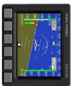
T2000ADSB - Équipement avionique Microair - Free user manual and instructions
Find the device manual for free T2000ADSB Microair in PDF.

| Product Type | ADS-B Transponder with 1090 MHz ADS-B Out and ATCRBS Mode 3A/C |
| Dimensions (L x W x H) | 145 mm x 61 mm x 61 mm (5.7 x 2.4 x 2.4 in) |
| Weight | 685 g (24 oz) |
| Input Power | 10–33 Vdc, 100–150 mA @ 28 V, 150–250 mA @ 14 V |
| Transmitter Frequency and Power | 1090 MHz ±0.2 MHz, 200 W pulse output |
| Receiver (1030 MHz) | −7 to −71 dBm dynamic range, ±5 MHz passband |
| Altitude Source Options | Internal altimeter, Gillham parallel, or serial (RS-232) encoder |
| Altitude Resolution | Internal: 1 ft displayed, 25 ft ADS-B; Serial: 25 ft or 100 ft depending on source |
| ADS-B Messages | Airborne (types 0, 11–18), Surface (types 0, 7, 8), Identification & Category (2–4), Airborne Velocity (19), Emergency/Priority (28), Operational Status (31) |
| ADS-B Version | V2 or V3 (selectable) |
| Supported Emitter Categories | A1 (Light <15,500 lbs), A7 (Rotorcraft), B1 (Glider), B2 (Lighter-than-air), B4 (Ultralight), C1–C5 (Surface vehicles/obstacles) |
| VFR Code | Default 1200, programmable via menu |
| ICAO Code & Aircraft ID | 24-bit hex code (0–9, A–E); Flight ID up to 8 alphanumeric characters |
| Panel Mounting | 57 mm (2.25 in) hole, 4 x M4 screws, depth clearance 200 mm (8 in) |
| Antenna Requirements | 1090 MHz transponder antenna (BNC), GPS antenna (TNC), static pressure line for internal altimeter |
| Cable Loss Limit | 2 dB from transponder to antenna; recommended RG400 coax |
| Maintenance Interval | Calibration and testing every 2 years (recommended) |
| Safety Notes | Installation by qualified avionics mechanic; avoid voltage transients; keep antenna 1 m from body; do not exceed bending radius of coax |
| Spare Parts & Repairability | Custom coax cables available from Microair; warranty excludes damage from misuse or transient voltages |
Frequently Asked Questions - T2000ADSB Microair
User questions about T2000ADSB Microair
0 question about this device. Answer the ones you know or ask your own.
Ask a new question about this device
Download the instructions for your Équipement avionique in PDF format for free! Find your manual T2000ADSB - Microair and take your electronic device back in hand. On this page are published all the documents necessary for the use of your device. T2000ADSB by Microair.
USER MANUAL T2000ADSB Microair
Microair Avionics has developed the T2000ADSB transponder to provide for aircraft surveillance requirements of ATCRBS Mode 3A/C with ADS-B.
This is a controlled document, and may not be copied, amended, or distributed without the prior consent of Microair Avionics Pty Ltd.
© Microair Avionics Pty Ltd
DOCUMENT REVISION STATUS
| Revision | Date | Change |
| 01R1 | 21/02/23 | Initial Release |
| 01R2 | 24/03/23 | Minor correction. Programming moved from User manual. Extended test and calibration section from user feedback. |
TABLE OF CONTENTS
1.0 INTRODUCTION 4
2.0 PANEL MOUNTING 5
3.0 ALTITUDE ENCODER 6
4.0 TRANSPONDER ANTENNA & COAX CABLE 7
4.1 MOUNTING 7
4.2 GROUND PLANE 7
4.3 COAXIAL CABLE 7
5.0 GPS ANTENNA 9
5.1 DASH MOUNTED ANTENNA 9
5.2 EXTERNAL MOUNTED ANTENNA 9
6.0 WIRING 10
6.1 GENERAL WIRING 10
6.2 AUDIO BEEP 11
6.3 SUPPRESSION IN 11
6.4 SUPPRESSION OUT 11
6.5 AIR/GND (PREVIOUSLY KNOWN AS EXTERNAL STANDBY) 11
6.6 EXTERNAL IDENT 11
7.0 INITIALIZATION AND SETUP 12
7.1 PROGRAM MODE 12
7.2 VFR CODE 12
7.3 ICAO CODE 13
7.4 EMITTER CATEGORY 13
7.5 AIRCRAFT ID 14
7.6 ENCODER SOURCE 14
7.7 ALTITUDE UNIT 15
7.8 BAROMETER UNIT (MB OR INHG) 15
7.9 AIR GROUND LOGIC 15
7.10 ADSB VERSION 16
7.11 EXIT PROGRAM 16
8.0 CALIBRATION & TESTING OF INSTALLATION 17
8.1 IFR6000 TEST PROCEDURE 17
8.2 ADSB TEST PROCEDURE 18
8.3 BACKGROUND INFORMATION ON INTEGRITY 19
8.3.1 INTEGRITY NUC 19
8.3.2 ACCURACY NAC 20
8.3.3 INTEGRITY SIL 20
9.0 WIRING DIAGRAMS 21
10.0 INSTALLATION DIMENSIONS 29
11.0 PIN ASSIGNMENTS 30
12.0 PANEL TEMPLATE 31
13.0 SPECIFICATIONS 32
1.0 INTRODUCTION
Microair recommends you familiarise yourself with this Installation Manual BEFORE you start installing your Microair T2000ADSB Transponder.

IMPORTANT NOTE
The T2000ADSB must be installed and tested by a suitably qualified and authorised Avionics mechanic and all structural changes, such as the GPS antenna installation, must be approved by a suitably qualified and authorised engineer or the aircrafts manufacturer.
The installer is responsible for ensuring that the installation meets all functional and regulatory requirements. If the T2000ADSB is installed by an aircraft owner, who has the appropriate authority to do so, they remain responsible for the ensuring the installation meets all functional and regulatory requirements.
Microair strongly recommends the use of an ADSB/Transponder test set such as the IFR6000 to validate the installation. Microair had an IFR6000 available for lease on a day rate basis.
If ADSB test equipment is not available then Microair recommends that as a minimum, a structured test flight is conducted with a detailed log maintained during the flight which can then be compared to the Flight Track Log from an ADSB tracking provider such as FlightAware or Flightradar24. We recommend that the flight log, the downloaded flight track and the comparison are filed in the aircrafts records as demonstration of a compliant installation.
2.0 PANEL MOUNTING
Determine a suitable location in the instrument panel in full view of both pilots. Cut a 57mm diameter (2 ¼ inch) hole with 4 x 4mm holes for the mounting screws. Dimensions for this are provided on the panel template. Allow a minimum of 63mm (2 ½ inch) square behind the cut out, to allow clearance from other instruments. A depth of 200mm (8 inches) is recommended to accommodate the transponder and electrical connectors.
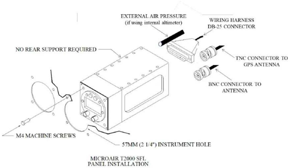
The T2000ADSB weighs only 685g (24oz). The four M4 x 12mm machine screws are sufficient to support the transponder. No rear support is required unless the panel structure itself is too weak to support the load.

IMPORTANT NOTE
Removal of the chassis screws for the purpose of attaching support bracket is not permitted.
The drilling of holes in the chassis for any purpose is not permitted.
Filings from changing the thread of the M4 screw may cause electrical faults. Faults of this type are NOT covered by warranty.
3.0 ALTITUDE ENCODER
The T2000ADSB has three options for its altitude source:
- An inbuilt altimeter that requires no connection to an external altimeter, mode C blind encoder or other EFIS system for its altitude data input. If using the inbuilt altimeter, connect the External Air Pressure static source directly to the 1/8" NPT male input on the rear side of the transponder and select the appropriate Encoder Source from the Program Mode user menu.
- A Gillham encoded external altimeter or mode C blind encoder.
- A serial encoded external mode C blind encoder or EFIS system.
For customers intending to use an installed altimeter, mode C blind encoder or other EFIS altitude source (either Gilham or serial) ensure installation is per the manufacturer's instructions and select the appropriate Encoder Source from the Program Mode user menu. An appropriate wiring harness is connected to the T2000ADSB via a DB25 connector (refer wiring diagram). The power for blind mode C encoders can be supplied from the T2000ADSB and is equal to the aircraft supply voltage. This power is switched when the T2000ADSB is turned on.
If the encoder is to be powered separately, it is recommended that a ground wire is run between the encoder and T2000ADSB to ensure correct switching of the data lines.

IMPORTANT NOTE
Most encoder manufacturers advise of a warm up period for their product before altitude data is supplied. The period can typically be up to 10 minutes. For the Microair EC2002, the warm up time is only 10 seconds!
Refer to WIRING DIAGRAMS (section 9.0) for wiring details and pin assignments for commonly used altitude encoders or EFIS, in both Gillham and serial data outputs.

IMPORTANT NOTE
If the aircraft voltage is 28V and the encoder is 14V only, a 28/14V converter should be installed between the T2000ADSB and the encoder.
Please ensure that the voltage supply line to power the encoder is NOT shorted to any data line or ground. The T2000ADSB will incur internal faults if a short occurs. This type of damage is NOT covered by the warranty.
4.0 TRANSPONDER ANTENNA & COAX CABLE
The T2000ADSB requires an antenna tuned to 1090MHz.
4.1 Mounting
The transponder signal is primarily directed to ground stations (Radar sites), hence the antenna is typically located on the underside of the fuselage. The position should give the antenna a full 360-degree view of the horizon. The position should be away from other protrusions from the airframe, such as footsteps, and undercarriage legs.
To avoid possible interference the antenna must be mounted a minimum of 0.3m (12 inches) away from the T2000ADSB. The transponder antenna outputs high levels of RF energy and should be located at least 1m (3ft) away from vulnerable part of the human body or be separated by a metal panel.
If the VHF comm antenna is already located on the underside of the fuselage, the transponder antenna should be located at least 1 metre (3ft) away. The transponder antenna should be mounted 2 metres (78 inches) from a DME antenna, and 1.5 metres (58 inches) from the ADF sense antenna.
4.2 Ground Plane
In metal skin aircraft the skin forms the ground plane. To ensure a good electrical connection, it may be necessary to remove paint/primer from the inside face of the skin, before attaching the antenna. This may be resealed after the antenna is installed. On pressurised aircraft, the antenna should be sealed using RTV-3145 or equivalent, to seal around the connector and mounting hardware. All antenna mounts should be sealed around the outside for moisture protection, using RTV-3145 or equivalent.
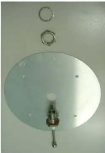
In a composite aircraft the skin of the airframe cannot be used, and a suitable ground plane must be fabricated. The ground plane is typically an aluminium disc with a radius equal to the height of the antenna (approx. 75mm or 3"). The antenna is mounted in the centre of the ground plane.
The ground plane does not have to be circular however, but the area should be approx the same size. Fibreglass aircraft can mount the ground plane on the inside of the aircraft.
Although carbon fibre is a good reflector of RF, it is not a suitable material for a ground plane. A metal ground plane is ideal.
It is important to ensure that a good electrical contact is established, as some antennas have sealing O-rings which can isolate this connection.
natural_image
Top-down view of a metallic circular component with a central knob and two small circular components above it (no text or symbols visible)4.3 Coaxial Cable
The T2000ADSB allows for 2dB cable loss from the unit to the antenna. The installer should consider carefully what type of coaxial cable is to be used, so that this loss limit is not exceeded. The cable should be terminated with a crimped BNC connector rated for 200Wpep and 2GHz such as the Amphenol 112514.
Microair recommends the use of RG400 coax cable in accordance with the table below.
| Cable | Bending Radius | Loss @ 1Ghz dB/m | Max Length | TX Power | RX Sensitivity |
| RG400 (Mil Spec) | 50mm (2") | 0.485dB/m | 3.9m 12.8ft | >125W | <-69dBm |

IMPORTANT NOTE
Do not exceed the minimum bending radius. Tight bends will introduce losses in the cable, which may affect the performance of the transponder.
When fixing the coax cable in the airframe, do not "strangle" the cable with tight cable ties. This can distort or damage the coax screen.
Avoid looping excess Coax cable. It is recommended that a coax cable correct to within 300mm (1ft) be ordered (available at microair.aero). If shortening a coax cable pay particular attention to the termination. A crimped connector rated for operation up to 2GHz and 200W is required such as the 112514 BNC Connector.
5.0 GPS ANTENNA
The T2000ADSB requires the installation of a GPS Antenna to receive a satellite GPS signal required by the unit. The GPS Antenna is connected to the T2000ADSB on the back of the unit via TNC connection. Two types of GPS Antennas are recommended for operation with the T2000ADSB transponder.
5.1 Dash Mounted Antenna
For composite skinned aircraft, a dash-mounted GPS antenna can be connected to the unit and positioned on the instrument dashboard in an unobstructed position. Maintain separation of the GPS antenna from other antennas located on the dashboard should these be present.

natural_image
Hand holding a small object with a blue arrow indicating rotation (no text or symbols)The Microair dash mounted antenna uses an adhesive pad to secure the antenna to the dash. Peel the label from the adhesive backing of the GPS antenna and firmly press the antenna into position on top of the instrument panel.
Other GPS dash mounted antennas may require a physical fixture to be installed on the dash. Ensure to follow the manufacturer's instructions for the installation of your dash mounted GPS antenna in such instances.

IMPORTANT NOTE
A magnetic fixing solution is not recommended for the GPS antenna as this may interfere with other instrumentation present.
5.2 External Mounted Antenna
For metallic skinned aircraft, it is recommended that a TSO'd externally mounted antenna is used. Position the GPS antenna on the upper side of the fuselage in an unobstructed position, preferably at the highest point of the aircraft when in level flight. To the extent practicable, mount the antenna so that the base is horizontal when the aircraft is in cruise attitude. Route the antenna cable in the most direct path practicable and reduce the cable length to the minimum required.
Ensure to follow the manufacturer's instructions for the installation of the Externally mounted antenna.

IMPORTANT NOTE
Avoid looping excess Coax cable. It is recommended that a coax cable correct to within 300mm (1ft) be ordered (available at microair.aero). If shortening a coax cable pay particular attention to the termination. A crimped connector rated for operation up to 2GHz is required such as the Amphenol 122372 (straight) or 122365 (right angle) TNC connector.
6.0 WIRING
The T2000ADSB must be installed with a wiring harness which meets the following requirements.
6.1 General Wiring
The T2000ADSB is to be powered from the aircraft supply, via the avionics master and fuse/circuit breaker with a maximum 5 amp rating (3 amp minimum).

IMPORTANT NOTE
The aircraft's electrical system may produce severe transient voltages during engine start and stop
Microair recommends that the avionics master be turned off during engine start and stop, to prevent damage occurring to the T2000ADSB.
Damage to the transponder as a result of transient voltages is NOT covered by the warranty.
Microair recommends that if used, the external encoder be installed and wired in accordance with the manufacturer's installation instructions. The encoder can be powered directly from the T2000ADSB.
It is very important to secure all D series plugs via their security screws before operation. Aircraft vibration may disconnect a D series plug if it not secured. Wiring is to be separated from the coaxial cables.
Microair recommends the following wire types for connection of the T2000ADSB:
| Power Input | 18 AWG TEFZEL 22759/16-16 | Red and Black Wire |
| External Connections | 22 AWG TEFZEL 22759/16-22 | Wire orSingle core shielded |
| 22 AWG TEFZEL 27500-22TG1T14 | ||
| Encoder Power | 22 AWG TEFZEL 22759/16-22 | Red and Black Wire |
| Encoder Data | 22 AWG TEFZEL 22759/16-22 | White Wire |
To ensure correct installation and to make future service simple, Microair recommends that all wiring be labelled for easy identification.
6.2 Audio Beep
The T2000ADSB beep function when set to ON, will emit a beep tone on this line. Audio beep should be taken to the Auxiliary input of the aircraft's radio or Audio Panel.
When connecting the beep function to the Microair M760 transceiver, simply join the beep line directly to any headphone line (orange wire in factory supplied harness).
6.3 Suppression IN
The suppression IN line is used in installations with multiple transponders or DME systems to “suppress” the T2000ADSB, to prevent concurrent transmissions, and interference. When another system transmits, it will send a positive voltage to the suppression IN, which prevents the T2000ADSB from transmitting.
The T2000ADSB requires a minimum signal voltage of 5V. The signal voltage may not exceed 20V.
In most installations the Suppression IN can be left unconnected.
6.4 Suppression OUT
Where the T2000ADSB is used in installations with multiple transponders or DME systems, the suppression OUT line is used to “suppress” other transponder and DME equipment installed in the aircraft, from interfering. When the T2000ADSB transmits, it raises a positive voltage on the suppression OUT line, which prevents the other equipment from transmitting.
The signal voltage is 5V.
In most installations the Suppression IN can be left unconnected.
6.5 AIR/GND (previously known as External Standby)
The T2000ADSB must know its airborne or surface status and provides two methods to achieve this:
-
An external switch can be wired to the T2000ADSB. This is usually a “Squat Switch” on the undercarriage or an “Air Switch” on the wings leading edge. The switch must pull the T2000ADSB input to ground when active but the T2000ADSB can be set for the active state to either be Surface (NORM) or Airborne (REV). Refer to Program Mode described below.
-
GPS speed can also be used to switch between Airborne and Surface modes. Ground speeds above 35kts will cause the T2000ADSB to switch to Airborne Mode whilst ground speeds below 20kts will cause the T2000ADSB to switch to Surface Mode.
6.6 External Ident
This line is typically wired to a momentary-ON switch, in a position more easily reached by the pilot / co-pilot (e.g. control column). When this line is taken to ground briefly, the T2000ADSB will go through its Ident function.
Most installations to not include an External Ident switch.

IMPORTANT NOTE
If any of the above wiring functions are not required, they can simply be left unwired.
7.0 INITIALISATION AND SETUP
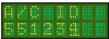
On initial power up the T2000ADSB will enter Program Mode to allow the ICAO Code (sometimes call the Mode S code) to be set. It is important that the Emitter Category and Aircraft ID are also set.
- If the ICAO Code and aircraft Registration were provided to Microair at the time of purchase then this data may have been preset.
The following procedures provide step by step instructions to program the transponder options.
| PROGRAM MODE | VFR CODE |
| ICAO CODE | |
| EMISSION CATEGORY | |
| AIRCRAFT ID | |
| ENCODER SOURCE | |
| ALTITUDE UNIT (ft/m) | |
| BAROMETER UNIT (Mb/inHg) | |
| AIR GROUND LOGIC | |
| ADSB VERSION | |
| EXIT PROGRAM |
7.1 PROGRAM MODE
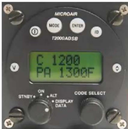
To start the T2000ADSB in PROGRAM MODE, hold down the MODE key whilst powering the device. Keep the MODE key held down until the start up self test messages have been displayed.
Each item can be adjusted to the desired value or option by scrolling the CODE SELECT knob. The selected value or option can be saved by pressing the ENTER key. PROGRAM MODE then moves to the next menu item.
NOTE: If the ICAO code is not set the T2000ADSB will always start in PROGRAM MODE as ADSB cannot operate without a valid code.


7.2 VFR CODE
This item sets the default VFR code which can be hot key accessed from the V (VFR) key. For most countries the default general aviation code is 1200.

| Press ENTER key | Until VFR CODE message appears |
| Rotate CODE SELECT knob | Adjust the digit highlighted by the cursor. |
| Press CODE SELECT knob | Moves the digit to the right |
| Press ENTER key | The message SAVED appears briefly on the display |
| The display moves to ICAOCODE menu item |
7.3 ICAO CODE
The ICAO code is an essential part of all ADS-B messages. The operator should check with the Civil Aviation Authority, to ensure what the correct ICAO code for their aircraft is.

| Press ENTER key | Until ICAOCODE message appears |
| Rotate CODE SELECT knob | Adjust the digit highlighted by the cursor. |
| Press CODE SELECT knob | Moves the digit to the right |
| Press ENTER key | The message SAVED appears briefly on the display |
| The display moves to EMIS CAT menu item |
The ICAOCODE is limited to the hex-decimal character set of numbers 0-9, and letters A-E.

IMPORTANT NOTE
All ADS-B message include the ICAOCODE data. No ADS-B operation will be possible if the ICAOCODE is not entered. The unit will not operate until this code is set.
7.4 Emitter Category
The emitter category is an essential piece of ADS-B data, which is used to describe the aircraft "type". The T2000ADSB has restricted the category selections to those which are required to transmit airborne ADS-B messages only

| Press ENTER key | Until EMIT CAT message appears |
| Rotate CODE SELECT knob | Scroll to select the desired Emission Category. The default is A0. |
| Press ENTER key | The message SAVED appears briefly on the display |
| The display moves to A/C ID menu item |
| Emission Category | Description |
| A1 | Light (< 15,500lbs) |
| A7 | Rotorcraft |
| B1 | Glider / Sailplane |
| B2 | Lighter – than – air |
| B4 | Ultralight / hang-glider / paraglider |
| C1 | Surface Vehicle - Emergency Vehicle |
| C2 | Surface Vehicle - Service Vehicle |
| C3 | Point Obstacle |
| C4 | Cluster Obstacle |
| C5 | Line Obstacle |
If you are uncertain of which emitter category is applicable to your aircraft, contact your civil aviation authority for advice. To ensure that ADS-B operation is possible, the emitter category is defaults to A1.
7.5 Aircraft ID
The Aircraft ID data is the default for the Flight ID which assists ATC to uniquely identify individual aircraft. The Flight ID is typically the aircraft's registration, but the operator should check with the Civil Aviation Authority for their correct Flight ID format.

The aircraft ID is the default for the flight ID in the MODE MENU. If the Flight ID is not entered the ADS-B message will transmit "null" in the Aircraft Identification message.
| Press ENTER key | Until A/C ID message appears |
| Rotate CODE SELECT knob | Adjust the digit highlighted by the cursor. |
| Press CODE SELECT knob | Moves the digit to the right |
| Press ENTER key | The message SAVED appears briefly on the display |
| The display moves to next menu item |
The Aircraft ID can have a maximum of 8 characters, and can consist of capital letters A-Z and the numbers 0-9 with spaces in the trailing unused positions (spaces are not allowed in or within the Flight or Aircraft IDs).
7.6 ENCODER SOURCE
The T2000ADSB is able to use altitude information from either its internal encoder, or serial or parallel (Gillham) altitude data. If Gillham is selected the T2000ADSB will detect altitude code over the 10 line Gillham interface. If serial is selected the T2000ADSB will detect altitude data over the RS-232 interface.


Serial data can be in any one of the following protocols.
- Garmin AT
- Magellan
- Northstar / Garmin
- Trimble / Garmin
- Microair Avionics
| Press ENTER key | Until ENCODER SOURCE message appears |
| Rotate CODE SELECT knob | Scroll to select the Altitude Source (Internal, Gillham, Serial). |
| Press ENTER key | The message SAVED appears briefly on the display |
| The display moves to EXIT PROGRAM menu item |
If the serial data supplies altitude with resolution to 25 foot increments, the T2000ADSB will transmit ADS-B message with the barometric altitude data resolved to 25 feet. The displayed altitude will also be resolved to 25 feet. Where the serial data supplies altitude with resolution to 100 foot increments, the transmitted and display altitudes will be resolved to 100 feet only. When the internal altimeter is selected the displayed altitude has a resolution of 1ft and the ADSB transmitted resolution will be 25ft.
7.7 ALTITUDE UNIT
The altitude data can be displayed in feet or meters. Once the Altitude units are set, all altitude data is displayed in these units.

| Press ENTER key | Until ALTITUDE UNIT message appears |
| Rotate CODE SELECT knob | Rotate the Code Select to select the unit (Feet or Meters) |
| Press ENTER key | The message SAVED appears briefly on the display |
| The display moves to EXIT PROGRAM menu item |
7.8 BAROMETER UNIT (Mb or inHg)
The barometric pressure units used by the T2000ADSB can be either MB = millibars, or HG = inches Mercury.

| Press ENTER key | Until BAROMETER UNIT message appears |
| Rotate CODE SELECT knob | Rotate the Code Select to select the unit (Mb or inHg) |
| Press ENTER key | The message SAVED appears briefly on the display |
| The display moves to EXIT PROGRAM menu item |
7.9 AIR GROUND LOGIC
For aircraft using the remote air/ground input line (pin 15), the operation of the switch can be changed by the software to suit the aircraft.

If the air/ground switch closes to ground when the aircraft is on the ground then the operation is Norm (normal).
If the air/ground switch closes to ground when the aircraft is in the air then the operation is Rev (reverse).
If the aircraft doesn't use an air/ground switch then select GPS which will use aircraft ground speed to determine air/ground logic for ADSB.
| Press ENTER key | Until AIR GROUND LOGIC message appears |
| Rotate CODE SELECT knob | Rotate the Code Select to select either Norm, Rev or GPS |
| Press ENTER key | The message SAVED appears briefly on the display |
| The display moves to EXIT PROGRAM menu item |
7.10 ADSB VERSION
Selects the versions of ADSB messaging which can be Version 2 or Version 3. Default is Version 2.
| Press ENTER key | Until ADSB VERSION message appears |
| Rotate CODE SELECT knob | Rotate the Code Select to select either Version 2 or Version 3 |
| Press ENTER key | The message SAVED appears briefly on the display |
| The display moves to EXIT PROGRAM menu item |
7.11 EXIT PROGRAM
This is the end of the PROGRAM MODE menu. The user can exit by pressing the ENTER key. The T2000ADSB will restart in the operational mode.

The user can exit the PROGRAM MODE menu at any time, from any menu item, by pressing the toggle key. To re-enter the PROGRAM MODE menu the T2000ADSB must be turned off, and re-started using the ON and MODE keys (refer PROGRAM MODE section).
8.0 CALIBRATION & TESTING OF INSTALLATION
Please refer to the Civil Aviation rules or regulations for your country to determine what the calibration requirements are for a transponder installation.
For certified aircraft, most countries will require a test of the installation to be carried out by a qualified test centre, along with a calibration of the encoder and altimeter in the aircraft. For experimental aircraft, most regulatory authorities requires that the installer be responsible to ensure that the installation meets the required functional performance.
This test is typically repeated every two years, to ensure the ongoing accuracy of the system.

IMPORTANT NOTE
It is vital to aircraft safety that all transponder/encoder/altimeter systems, which will operate within an SSR system or interact with TCAS equipped aircraft, perform to a minimum civil aviation standard.
For this reason, Microair strongly recommends that all transponder installations be calibrated at the time of installation, and at periods of not greater than two years thereafter.
8.1 IFR6000 Test Procedure
Refer to FAA FAR Part 43 appendix E and F for typical transponder/encoder/altimeter equipment calibration procedures. The diagram below illustrates a standard set up for the testing of the transponder/encoder/altimeter equipment.
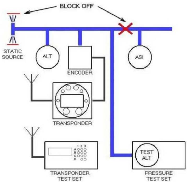
flowchart
graph TD
    A["STATIC SOURCE"] --> B["TRANSponder"]
    B --> C["TEST SET"]
    B --> D["TRANSPONDER TEST SET"]
    D --> E["STRESS TEST SET"]
    F["BLOCK OFF"] --> G["ASI"]
    H["ALT"] --> I["ENCODER"]
    J["A"] --> K["1 2 3"]
    L["B"] --> M["C"]
    N["C"] --> O["D"]
    P["D"] --> Q["D"]
    R["A"] --> S["A"]
    T["A"] --> U["B"]
    V["A"] --> W["C"]
    X["A"] --> Y["D"]
    Z["A"] --> AA["B"]
    AB["X"] --> AC["×"]
8.2 ADSB TEST PROCEDURE
Microair recommends the use of an IFR6000 test set for use in the validation of ADS-B installations.
Note, before commencing your test, ensure that the aircraft GPS has a clear view of the sky / GPS constellation to be able to generate good HPL/NIC. Normally, testing within the confines of a hangar will not yield acceptable results. Ensure GPS has established a position prior to carrying out these tests (this can be checked by pressing (I) in the Disp Alt mode and confirming time, LAT, LON etc are present)
Set up the IFR6000 per the manufacturer's instruction for ADSB monitoring ensuring the following settings:
- Ensure that ADSB MON is set to DF18.
- Ensure the aircrafts Mode S address is entered.
Select ADSB Version 2 on the T2000ADSBs Program menu.
With the aircraft in Surface mode (i.e. Squat switch active, Air switch inactive or GPS speed below 20kts) ensure the following messages are available:
- SURFACE POS. Confirm the ICAO code, Position (LAT/LON) and NIC/Rc are correct.
- IDENT & CAT. Confirm the ICAO code, Flight ID and Emitter Category are correct.
- A/C STATUS ST1. Confirm the ICAO code and Mode A code are correct. Enter code 7500, 7600 or 7700 on the T2000ADSB and ensure the EMERG/PRIOR Code is correct.
Simulate the aircraft being in the air (follow the aircraft maintenance manual or often the easiest way is to enter Program Mode on the T2000ADSB and change the AIR/GND Logic from Norm to Rev or vice versa). Ensure the following messages are available:
- AIRBORNE POS. Confirm the ICAO code, Position (LAT/LON), Altitude and NIC/Rc are correct.
- AIRBORNE VAL. Confirm the ICAO code, Velocity (E-W, N-S), vertical rate and NACV are correct.
- IDENT & CAT. Must be present but no further testing required is performed for Surface message.
- A/C STATUS ST1. Must be present but no further testing required is performed for Surface message.
8.3 BACKGROUND INFORMATION ON INTEGRITY
8.3.1 Integrity NUC
If the aircraft is transmitting SURFACE squits (eg: squat switch is active), then the type code needs to be 5,6 or 7 in accordance with the table below.
| Type code | Rc | NUC | Validity |
| 5 | <7.5m | 9 | Valid |
| 6 | <25m | 8 | Valid |
| 7 | <185.2m | 7 | Valid |
| 8 | >185.2m | 6 | Not useable – indicates no Integrity |
If the aircraft is transmitting AIRBORNE extended squiters then the type code needs to be 9-15 in accordance with the table below.
| Type code | Rc | NUC | Usable by ATC | Observed frequency of type code (as expected) |
| 9 | <7.5m | 9 | Yes | Rare |
| 10 | <25m | 8 | Common | |
| 11 | <185.2m | 7 | Common | |
| 12 | <0.2 nm | 6 | Common | |
| 13 | <0.5 nm | 5 | Less Common | |
| 14 | <1.0nm | 4 | Infrequent | |
| 15 | <2.0 nm | 3 | No | Unlikely |
| 16 | <10 nm | 2 | ||
| 17 | <20 nm | 1 | ||
| 18 | >20 nm | 0 | Not useable – indicates no Integrity | |
A “good” installation needs to transmit a NIC of at least 6, 7 or 8. A lower NIC for any period indicates something is wrong.
The containment radius (Rc or Horizontal Protection Level HPL) is calculated by the GPS receiver based on which GPS satellites it is receiving and the satellite geometry. It does not depend on actual measurements of the received satellites. Aircraft in the same position should calculate almost the same HPL value when exposed to the same satellite constellation.
Aircraft with a clear view of the sky should be generating HPL values below 0.2 nautical miles a very large percentage of the time. Therefore expect to see NIC=7,8 or 9. Nearly all aircraft output NIC=6 to 9 all the time. A NIC=5 or 4 only occurs very rarely when there is a GPS constellation issue. If NIC=5 or below then something is probably wrong because real HPLs do not get this low.
8.3.2 Accuracy NAC
It is important that NAC be non zero. NAC is reported in Type 31 and Type 29 messages. The aircraft HFOM needs to be 5-11 as per the table below.
| HFOM | NAC | Usable by ATC |
| <3m | 11 | Yes |
| <10m | 10 | |
| <30m | 9 | |
| <0.05nm | 8 | |
| <0.1nm | 7 | |
| <0.3nm | 6 | |
| <0.5nm | 5 | |
| <1nm | 4 | No |
| <2nm | 3 | |
| <4nm | 2 | |
| <10nm | 1 | |
| <20nm | 0 | Not useable – indicates no accuracy |
8.3.3 Integrity SIL
It is important that SIL be a value of 3. SIL is reported in Type 31 and Type 29 messages.
| SIL | Integrity |
| 0 | No integrity |
| 1 | Inadequate Integrity |
| 2 | Acceptable Integrity |
| 3 |
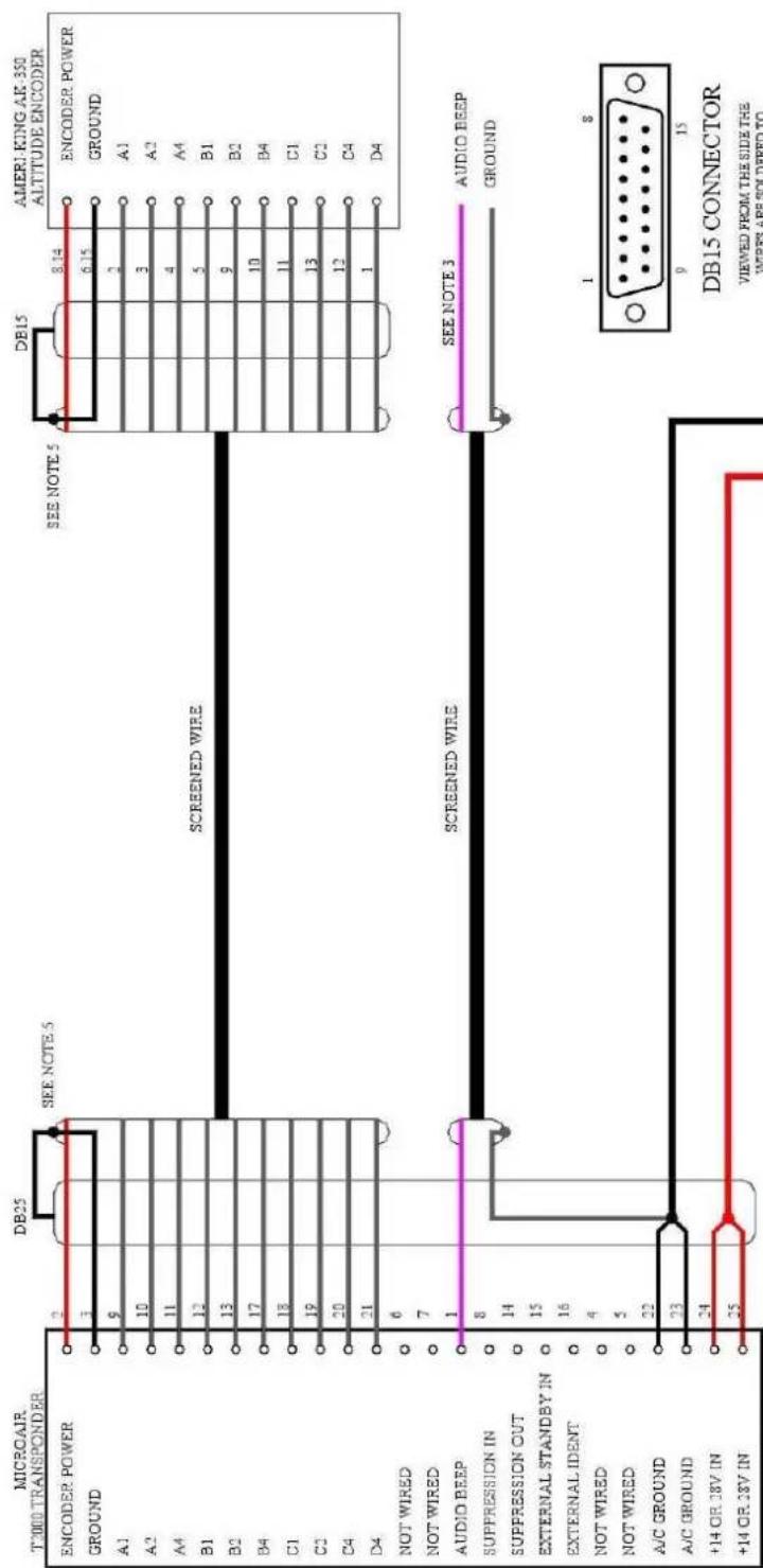
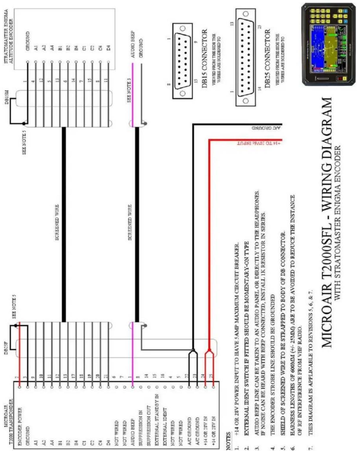
9.0 WIRING DIAGRAMS
The drawings defined below for the T2000SFL, are all applicable to the new T2000ADSB and can be installed as approved harnesses.
- T2000SFL with EC2002 Altitude Encoder – Serial
• T2000SFL with EC2002 Altitude Encoder - Gillham
• T2000SFL with AK-350 Altitude Encoder
• T2000SFL with A-30 Altitude Encoder
• T2000SFL with Enigma Multi-Function Display - T2000SFL with Dynon D10A Multi-Function Display – Gillham
• T2000SFL with Dynon D10A Multi-Function Display - Serial

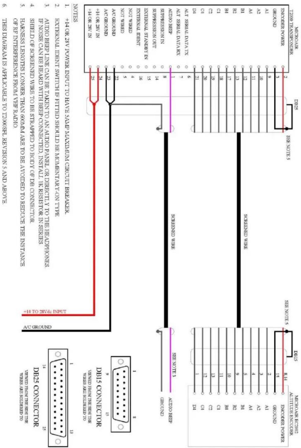
MICROAIR T2000SFL - WIRING DIAGRAM WITH MICROAIR EC2002 ENCODER
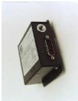
natural_image
Black electronic device with labeled ports and a central port (no visible text or symbols)
natural_image
Close-up of a black electronic device with a 24-pin connector and a visible I/O port (no text or symbols)MICROAIR T2000SFL - WIRING DIAGRAM
WITH MICROAIR EC2002 ENCODER (GILTHAM)
NOTES
natural_image
Electronic device with black casing and red connector (no visible text or symbols)MICROAIR T2000SFL - WIRING DIAGRAM WITH AMERI-KING AK-350 ENCODER

MICROAIR T2000SFL - WIRING DIAGRAM
WITH ACK A30 ENCODER

MICROAIR T2000SEL - WIRING DIAGRAM
WITH DVNON D10A / D100 / D180 ENCODES
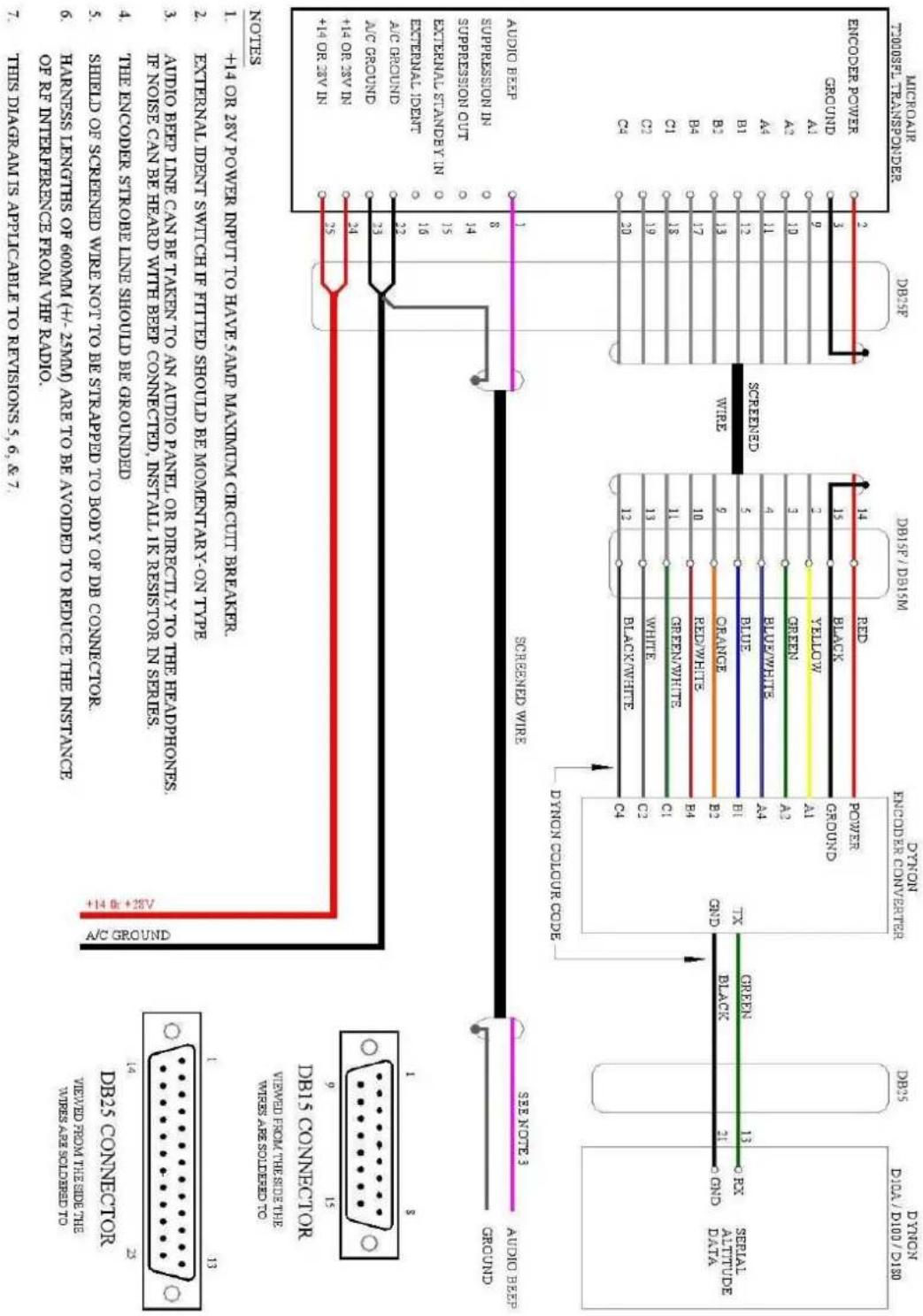
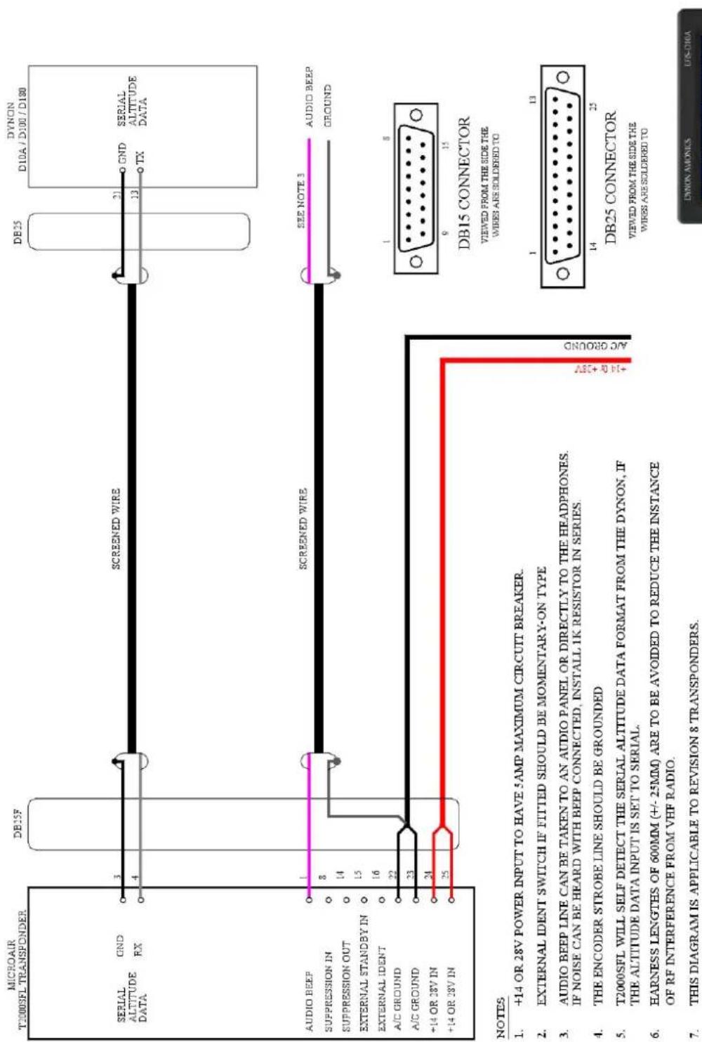
MICROAIR T2000SFL - WIRING DIAGRAM WITH DYNON D10A / D100 / D180 ENCODERS

10.0 INSTALLATION DIMENSIONS
11.0 PIN ASSIGNMENTS
| Pin | Assignment |
| 1 | BEEP AUDIO TONE |
| 2 | ENCODER SWITCHED POWER OUT (= A/C POWER) |
| 3 | GROUND |
| 4 | ALT SERIAL DATA RX |
| 5 | ALT SERIAL DATA TX |
| 6 | NOT WIRED |
| 7 | NOT WIRED |
| 8 | SUPPRESSION IN (5 TO 20V) |
| 9 | GILLHAM CODE A1 |
| 10 | GILLHAM CODE A2 |
| 11 | GILLHAM CODE A4 |
| 12 | GILLHAM CODE B1 |
| 13 | GILLHAM CODE B2 |
| 14 | SUPPRESSION OUT (5V) |
| 15 | EXTERNAL STANDBY (GROUND TO OPERATE) |
| 16 | EXTERNAL IDENT (GROUND TO OPERATE) |
| 17 | GILLHAM CODE B4 |
| 18 | GILLHAM CODE C1 |
| 19 | GILLHAM CODE C2 |
| 20 | GILLHAM CODE C4 |
| 21 | GILLHAM CODE D4 |
| 22 | A/C GROUND |
| 23 | A/C GROUND |
| 24 | A/C POWER (+10V TO +33V) |
| 25 | A/C POWER (+10V TO +33V) |

DB25 CONNECTOR
VIEWED FROM THE SIDE THE WIRES ARE SOLDERED TO
12.0 PANEL TEMPLATE

13.0 SPECIFICATIONS
| TSO Equivalence | C74c Class 1a TransponderC166b Class B0 1090MHz ADS-B Out (with Class B1S power output and antenna configuration) – meets all relevant 14CFR 91.227 requirements.C196b Position SourceC106c and C88a Altimeter (to 30,000') |
| Transmitter | 1090MHz +/-0.2MHz200W Pulse Output |
| Receiver (1030MHz) | -7 to -71dBm Dynamic Range1030MHz Centre Frequency+/-5MHz Pass band |
| Input Power | 10-33Vdc100-150mA @ 28V150-250mA @ 14V |
| Transponder Modes | StandbyMode 3AMode 3A/C |
| ADSB Messages | Airborne (Types 0, 11-18)Surface (Types 0, 7, 8)Identification and Category (Types 2-4)Airborne Velocity (Type 19)Emergency/Priority Status (Type 28 Subtype 1)Operational Status (Type 31) |
| Dimensions | Length 145mm (5.7")Width 61mm (2.4")Height 61mm (2.4") |
| Weight | 685g (24 oz) |


- TABLE OF CONTENTS
- INTRODUCTION
- IMPORTANT NOTE
- PANEL MOUNTING
- ALTITUDE ENCODER
- TRANSPONDER ANTENNA & COAX CABLE
- Mounting
- Ground Plane
- Coaxial Cable
- GPS ANTENNA
- Dash Mounted Antenna
- External Mounted Antenna
- WIRING
- General Wiring
- Audio Beep
- Suppression IN
- Suppression OUT
- AIR/GND (previously known as External Standby)
- External Ident
- INITIALISATION AND SETUP
- PROGRAM MODE
- VFR CODE
- ICAO CODE
- Emitter Category
- Aircraft ID
- ENCODER SOURCE
- ALTITUDE UNIT
- BAROMETER UNIT (Mb or inHg)
- AIR GROUND LOGIC
- ADSB VERSION
- EXIT PROGRAM
- CALIBRATION & TESTING OF INSTALLATION
- IFR6000 Test Procedure
- ADSB TEST PROCEDURE
- BACKGROUND INFORMATION ON INTEGRITY
- Integrity NUC
- Accuracy NAC
- Integrity SIL
- WIRING DIAGRAMS
- PIN ASSIGNMENTS
- PANEL TEMPLATE
- SPECIFICATIONS
Brand : Microair
Model : T2000ADSB
Category : Équipement avionique