
M760 - Radio transceiver Microair - Free user manual and instructions
Find the device manual for free M760 Microair in PDF.

| Product Type | Uncategorized electronic device |
| Brand | Microair |
| Model | M760 |
| Dimensions (H x W x D) | 2.5 x 6.0 x 8.0 inches (63 x 152 x 203 mm) |
| Weight | 1.2 lbs (0.54 kg) |
| Power Supply | DC 12V, 1.5A max |
| Power Consumption | 18W max |
| Display | Backlit LCD, 2 lines x 16 characters |
| Keypad | Membrane keypad with 12 keys |
| Audio Output | Built-in speaker, 2W |
| Audio Input | External microphone jack (3.5mm) |
| Main Functions | Communication, monitoring, data entry, menu navigation |
| Memory | Non-volatile, 100 channel presets |
| Operating Temperature | -20°C to +55°C |
| Storage Temperature | -40°C to +70°C |
| Humidity | 0-95% non-condensing |
| Maintenance | Clean with soft dry cloth; avoid solvents |
| Safety | Use only specified power supply; avoid water exposure |
| Spare Parts & Repairability | Contact authorized service center; limited user-serviceable parts |
| Certifications | FCC, CE, RoHS |
Frequently Asked Questions - M760 Microair
User questions about M760 Microair
0 question about this device. Answer the ones you know or ask your own.
Ask a new question about this device
Download the instructions for your Radio transceiver in PDF format for free! Find your manual M760 - Microair and take your electronic device back in hand. On this page are published all the documents necessary for the use of your device. M760 by Microair.
USER MANUAL M760 Microair
natural_image
White small airplane with red markings flying against a mountainous background (no visible text or symbols)M760
TRANSCEIVER
INSTALL & USER
MANUAL

Microair Avionics Pty Ltd
Airport Drive
Bundaberg
Queensland 4670
Australia
Tel: +61 7 41 553048
Fax: +61 7 41 553049
e-mail: sales@microair.com.au

About This Document
This manual describes the various installation configurations available for the Microair M760 Transceiver. The Transceiver's controls and design features are described and illustrated.
This is a controlled document and may not be amended, copied or distributed, without the prior consent of Microair Avionics Pty Ltd.
© Microair Avionics Pty Ltd
Ensure that the M760 transceiver is switched off during engine starting and stopping to avoid damage occurring.
CURRENT REVISION STATUS
| Revision Date Change | ||
| K | 31/01/00 | Initial release |
| L 18/11/01 | Additional install data and wiring diagram added | |
| M 04/10/02 | Additional wiring diagram added | |
| N 08/12/03 | Updated for revision N | |
| P 01/10/06 | Updated for revision P | |
| 01R3 | 13/10/06 | Updated for proposed functionality of revision P |
| 01R4 30/05/07 | Proposed functionality for revision P amended | |
| 01R5 | 28/06/07 | Updated for functionality as of M760_MICRO_1-3-3 |
| 01R6 | 3/06/08 | Warranty Statement Upgrade |
| 01R7 08/12/08 | Updated for revision P2 | |
| 01R8 | 25/2/09 | Updated Limited Warranty Statement & deleted Warranty cards |
| 01R9 | 24/4/09 | repair@microair.com.au added to Warranty Statement |
| 01R10 | 24/4/09 | Updated for revision Q |
| 01R11 | 13/07/09 | Additional Installation data added |
TABLE OF CONTENTS
1.0 INTRODUCTION....4
2.0 UNPACKING 4
USER / INSTALL MANUAL 4
NAMEPLATE DETAILS....4
AUTHORISED RELEASE CERTIFICATE....4
3.0 INSTALLATION....5
WIRING....6
COAX TERMINATION 8
ANTENNA 8
METAL SKIN AIRFRAMES....9
NON-METAL SKIN AIRFRAMES 9
POWER....10
BACKLIGHTING....10
POWER SAVINGS....10
MICROPHONE....11
ELECTRET 11
DYNAMIC....11
SPEAKER 11
INTERNAL VOX INTERCOM....12
HEADSET ADJUSTMENT 12
SIDETONE....12
MIC GAIN....12
EXTERNAL INTERCOM....13
DUAL COMM INSTALLATION....13
AUXILIARY AUDIO 14
DATA INTERFACE (SL30)....15
TRANSCEIVER FUNCTION 16
TRANSCEIVER STATUS 16
PC INTERFACE....16
NOISE SUPPRESSION....17
POWER FILTER....17
FERRITE CHOKES....17
4.0 OPERATIONAL CONTROLS....18
PRIORITY SWITCH....19
VOLUME / SQUELCH KNOB 19
ANNUNCIATOR LED 19
MODE SWITCH....20
TOGGLE SWITCH 20
FREQUENCY ADJUST KNOB 21
REMOTE MEMORY BUTTON....22
PUSH TO TALK BUTTON 22
5.0 OPERATIONAL MODES....23
ACTIVE/STANDBY MODE 23
108 TO 118 MHZ TUNING ....23
MONITOR FUNCTION....24
CHANNEL MODE....26
VOX MODE 27
6.0 PROGRAM MENU....28
CD LOCKOUT 28
VOX 29
MONITOR SETUP 29
NEW MEMORY CHANNEL 30
SET FREQUENCY 30
SET LOCATION....30
SET SERVICE 30
EDIT MEMORY CHANNEL 31
EXIT MENU 31
7.0 WIRING DIAGRAM....32
IFICATIONS M760Q 33
9.0 DRILLING TEMPLATE 34
TED WARRANTY 35
1.0 INTRODUCTION
Thank you for purchasing this Microair product. The M760 is a 760 channel VHF aircraft transceiver, packaged to fit a standard 57mm (2 14 ) instrument hole. The M760 has been produced in accordance with CASA APMA approval E2000-004.
2.0 UNPACKING
The M760 is boxed in polystyrene for physical protection, and wrapped in an anti-static bag for electrical protection. Once the box is opened and the radio unwrapped, the owner is responsible for physical and electrical protection.
Enclosed with the radio are: User / Install Manual
| CASA | form | 1 | - | release | certificate |
| DB15 | solder | plug | and | backshell | |
2.1 USER / INSTALL MANUAL
Please read this manual completely before attempting to install or operate this radio. There are several installation options you may wish to consider, which are clearly laid out in the installation section.

IMPORTANT NOTE
This manual may be used as technical data to support an installation under the FAA form 337 process.
The M760 has all of the basic radio operations, and many other management and programming options, which are described in the operation and memory sections of this manual.
Please refer to the Microair Avionics Website www.microair.com.au for more installation information.
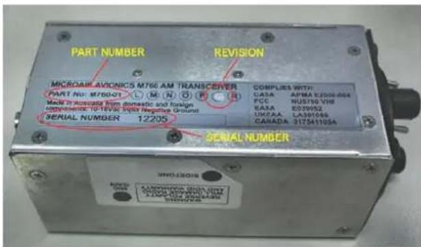
2.2 NAMEPLATE DETAILS
The M760 has a nameplate fixed to the bottom plate of the chassis.
The Nameplate records the M760's part number, revision, and serial number.
Microair recommends the M760 serial number be noted in the aircraft's maintenance records for future reference.
2.3 AUTHORISED RELEASE CERTIFICATE
The CASA form 1 – release note is an internationally recognised document which clearly identifies the part/component the form 1 is associated with. Please keep this certificate with the aircraft's file or log book.
3.0 INSTALLATION
The M760 has a simple physical installation for aircraft instrument panels. Select or cut a 57mm (2 1/4") instrument hole for mounting (refer panel drilling template in section 9.0).
For panel locations which do not afford sufficient space behind the radio to reach the connectors, Microair recommends connecting the wiring harness and coax cable before fitting the radio to the hole in the panel.
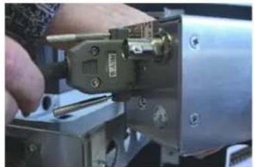
natural_image
Close-up of a hand using a tool to adjust or install a mechanical component (no visible text or symbols)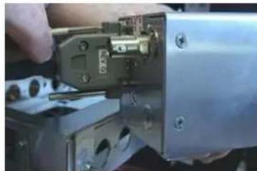
natural_image
Close-up of a mechanical assembly with a hand holding a tool, no visible text or symbols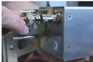
natural_image
Close-up of a hand inserting a metallic mechanical component into a metal housing (no visible text or symbols)Present the M760 to the rear face of this hole. The stepped round face will insert through the hole, and should appear flush with the front of the instrument panel when correctly positioned. Rotate the M760 to align the four M4 machine screws.
Loose fit all four M4 screws. For installations where the existing instrument panel screw holes are 1/8", the holes will need to be enlarged to 5/32" to fit the M4 machine screws.
Insert and tighten all four M4 machine screws. The M760 requires no rear support, the M4 screws provide all of the physical mounting required.
The M760 should be located in the aircraft within view of the pilot seated in the pilot-in-command position, and afford this pilot good access to the front face controls.

Do NOT oversize the mounting holes in the front face of the radio, to an imperial size. Drilling will damage internal components.
Do NOT replace the M4 machine screws supplied with the radio with longer screws. Over-length screws will touch or even crush internal components and cause damage.
Either of these actions will void the warranty
3.1 WIRING
Microair recommends the use of the wiring in the table below for the various parts of the radio harness:
| Pin Line Wire | ||
| 1 Pilot Microphone Tefzel 22 awg single core shielded | ||
| 2 RS232 RX Tefzel 22 awg two core shielded (with RS232 TX) | ||
| 3 Co-pilot Microphone Tefzel 22 awg single core shielded | ||
| 4 Dual Comm Suppression Tefzel 22 awg | ||
| 5 RS232 TX Tefzel 22 awg two core shielded (with RS232 RX) | ||
| 6 Auxiliary Audio Input Tefzel 22 awg single core shielded | ||
| 7 PTT Tefzel 22 awg two core shielded (with Memory) | ||
| 8 Backlighting Tefzel 22 awg | ||
| 9 Power Tefzel 22 awg | ||
| 10 Power Tefzel 22 awg | ||
| 11 Ground Tefzel 22 awg | ||
| 12 Ground Tefzel 22 awg | ||
| 13 Memory Tefzel 22 awg two core shielded (with PTT) | ||
| 14 Headphone Tefzel 22 awg single core shielded (Pilot & Co-pilot) | ||
| 15 Speaker Tefzel 22 awg single core shielded | ||
| BNC Aerial RG58C/U 50 ohm Coaxial Cable | ||
All wiring is connected by soldering to the DB15 connector. Inspect the solder cup side of the DB15 carefully to determine the pin numbering.

natural_image
Close-up of a 16-pin VGA connector with terminal pins (no text or symbols visible)Strip the insulation back 2mm (1/16"), and "tin" the exposed conductor with solder. Slide a 5mm length of 1.6mm (1/16") heatshrink tubing over the end of the wire. After checking the wiring diagram for the correct pin number, push the "tinned" end into the "tinned" solder cup, and solder into place. Check the soldered joint has been made, by gently pulling on the wire. Slide the heatshrink tubing down over the soldered pin, to completely cover the conductor.

Tinned Solder Cup Solder Wire to Cup Heatshrink
Cover the soldered joints with the grey plastic backshells. Ensure that the thumbscrews are in place before closing the backshells. Connect to the rear of the radio with a push fit, and secure the thumbscrews (top and bottom).

natural_image
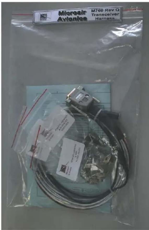
Close-up of a mechanical device labeled 'REV Q' with metallic fittings and a black cable (no readable text beyond label)Microair recommends the use of its pre-wired M760 harness. The harness is available from Microair, and comes complete with all switches, sockets, buttons, and mounting hardware.
Separate lines have been wired for Pilot and Co-pilot:
- Headphone
- Microphone
- PTT
- Remote Memory
3.2 COAX TERMINATION
The coax is cut to length and terminated in a BNC connector. Soldered or crimp type connectors are preferred to the solderless variety, as they have lower signal loss and better shielding.
Microair recommends using only soldered or crimped BNC connectors.
Solderless BNC connectors are NOT recommended, as their performance is not good enough for VHF transmissions.

3.3 ANTENNA
For certified aircraft the M760 should only be operated with a TSO compliant antenna. The antenna may be 14 wave whip or 12 wave dipole, using 50ohm coaxial cable and a BNC connector for connection. The VSWR should ideally be less than 2:1 across the 118.000MHz to 136.975MHz airband.
For non-certified aircraft using a non-TSO compliant antenna, the VSWR must be checked to ensure the ratio does NOT exceed 3:1 on 118.000MHz, 127.000MHz, and 136.975Mhz. The M760 will tolerate a VSWR of 5:1 without injury to the transceiver, but the performance is severely deteriorated.

Do not use the stubbie "rubber duckie" antennas meant for use with handheld radios.
3.3.1 METAL SKIN AIRFRAMES
For metal skin aircraft a 14 wave whip is the easiest antenna to fit. Ensure that the antenna base and the coax shield are firmly grounded to the skin of the airframe, on the inside of the aircraft. Ensure that any anti-corrosion product, which may be used to seal the exterior surface, does not isolate the antenna base from the airframe. For best performance the whip should be straight and vertical, when mounted on the airframe.
Refer to the Microair Avionics website www.microair.com.au for more detail on antennas suitable for metal skin airframes.
3.3.2 NON-METAL SKIN AIRFRAMES
For non-metal airframes, a 14 wave whip may still be used, but a ground plane must be installed, on the inside face of the aircraft skin. The ground plane should ideally be circular, and as a minimum, have a diameter of half the height of the whip. The ground plane should be fabricated from a lightweight metal, eg thin aluminium sheet. For best performance the whip element should be as vertical as possible.
An alternative antenna for non-metal airframes is the Ground Plane independent dipole. This antenna is physically similar to the 14 wave whip, but has a small flexible stub antenna pointing downwards from the antenna base. The stub section of the antenna takes the place of the ground plane, and simplifies installation.
Avoid mounting locations which position the antenna parallel to nearby metallic airframe structures such as tube framing, brackets, ribs, or frames. Metal objects which are close and parallel to the antenna will adversely affect performance.
If the installation has two radios, the two antennas should be separated horizontally by at least the length of the antenna. In the case of airband antennas this should be approx 1m (3ft). The further apart the better.
Beware of fabric surfaces with silver dope finishes. The silver dope is a conductive surface, and will screen antennas which are mounted internally.
Refer to the Microair Avionics website www.microair.com.au for more detail on antennas suitable for non-metal skin airframes.
3.4 POWER
The M760 is designed to operate on a 14V aircraft electrical supply. The radio will operate down to 10.7V on receive.

It is unlikely that a power supply operating below 11V would have sufficient power to allow clear transmissions.
The M760 will draw up to 1.8A when transmitting.
Low power will produce a BURRRRRRRRR signal.
NEVER operate the M760 on voltage exceeding 16V.

Damage will occur if the M760 is operated from power supplies which exceed 16V, even for very short (transient) periods.
Operation on a supply which exceeds 16V will void the warranty.
The M760 has a FET switch and internal fuse to protect against reverse polarity. If reverse polarity is applied the internal fuse (4A) will blow. Damage however may not be limited to the fuse.

Please ensure that the correct polarity is observed. The most common reason for reverse polarity, is misreading the pin assignments on the DB-15 connector.
Applying reverse polarity to the M760 will void the warranty
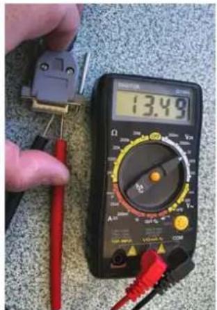
Check your wiring! Always check the voltage at the DB15 BEFORE it is plugged into the radio.
Use a multi-meter to check the voltage at the following pins:
Positive
Pin 9
Negative
Pin 11
Positive
Pin 10
Negative
Pin 12
3.4.1 BACKLIGHTING
The backlighting is activated, by taking input supply voltage to pin 8. This line can be individually switched outside the DB15 connector to enable the backlighting to be turned off.
3.4.2 POWER SAVINGS
For installations, operating from a battery only, Microair recommends saving battery power by NOT wiring the backlighting – do NOT wire pin 8. The backlighting will draw an additional 80mA of power. This nearly doubles the standby power demand.
Not connecting the backlighting can effectively double the running time on your battery.
3.5 MICROPHONE
The M760 can be operated with an Electret Insert or Amplified Dynamic microphone. These alternatives cover most aviation headsets and hand microphones.
When the PTT is pressed both microphones are live. To reduce background noise, the M760 can be installed with relays across the mic lines and the PTT line, to allow only one microphone at a time to operate.
3.5.1 ELECTRET
Electret microphones are the most common microphone in use on aviation headsets. They are small in size, and can have noise cancelling capability. It is important to wire the Electret microphone with the correct polarity. The Electret will only work if the positive and negative are wired correctly.
Electrets are a high signal device, and do not normally require amplification. Some headset manufacturers elect to use an amplifier to improve the Electret's response, and to provide some noise filtering.
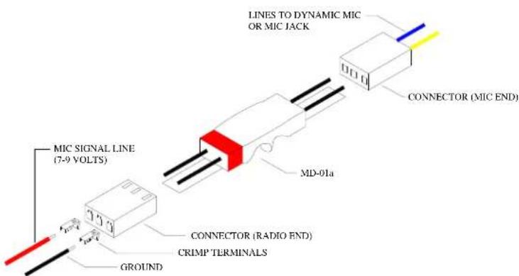
3.5.2 DYNAMIC
Dynamic microphones are a low signal device. A dynamic microphone will not operate directly with an M760 radio, because of the low signal produced.
For operators wanting to use a dynamic microphone, a mic amplifier must be used. Microair recommends the installation of the Microair MD-01a amplifier. This amp is compatible with 150-600 ohm dynamic microphones.
Refer to the Microair Avionics website www.microair.com.au for further details on microphone types, and wiring configurations.
3.6 SPEAKER
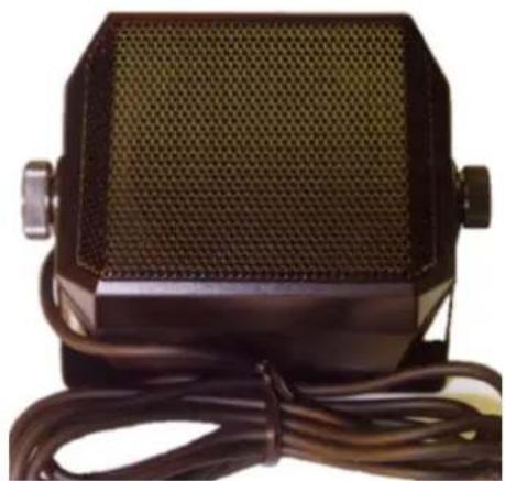
Microair recommends using a speaker of 8 ohms impedance, rated at a minimum of 5 watts. The speaker is wired to the speaker line (pin 15). Do NOT attempt to connect a speaker to the headphone line (pin 14). Likewise do NOT attempt to connect the headphones to the speaker line.
Microair recommends the SP01 Box Speaker. The SP01 has a durable thick film plastic cone of 8 ohms, and is rated at 5 watts. The SP01 is fitted with a mounting bracket, and 1.5m of screened cable.
Check your speaker installation by ensuring the audio is clear all the way up to full volume.
natural_image
Close-up of a black rectangular electronic device with mesh grille and attached cable (no visible text or symbols)3.7 INTERNAL VOX INTERCOM
The M760 is fitted with a VOX intercom feature which utilises the sidetone facility of the radio. The VOX threshold level is controlled in software by use of the VOX Adjust Mode. See section 5.4 to adjust the internal VOX intercom.
3.8 HEADSET ADJUSTMENT
It is important to ensure that the sidetone and mic gain are set to the correct levels, for best headset performance. The sidetone level will set the intercom's headset volume. The mic gain will set the level of microphone sensitivity for each headset.
3.8.1 SIDETONE
Adjust the sidetone if necessary for good volume level in the headset using the intercom. Ensure that the headset volume adjust (typically a knob located on the headset earcup) is set to mid range, so the volume came be adjusted up/down by the user.
3.8.2 MIC GAIN
Adjust the microphone gain if necessary for best audio “quality” not volume level, when transmitting. The M760Q is fitted with separate mic gain trimpots to allow for adjustment of individual headsets.
Punch the black dot carefully with a screwdriver blade, to expose the slotted plastic head of the trimpot, located approx 3mm (1/8") below the surface of the casing. The second mic gain position is not marked, refer to the drawing below for location.
Note the position of the slot before making adjustments. Use a small flat bladed screwdriver to make adjustments before testing with a headset again. The total movement of all trimpots is only 300 degrees (4/5 ^th turn). The factory setting positions the slot of the trimpots at 10 O'clock.


Do not attempt to adjust the modulation or power output. These adjustments can only be set correctly by a qualified technician. Adjustment of the power output or modulation by anyone other than Microair or their approved agent will void the warranty.
3.9 EXTERNAL INTERCOM
Where the M760 is to be installed with an external intercom, the internal VOX intercom should be disabled in the Program Mode Menu. See section 6.2.
Wire only a single mic line (pin 1), along with the PTT (pin 7), the headphone (pin 14), and a ground line (pin 11 or 12) to the intercom. Follow the intercom manufacturer's instructions for further installation.
Wire the remote memory line (pin 13), directly to the remote memory button location. This line is NEVER connected to the external intercom. Refer to the Microair Avionics website www.microair.com.au for more details and wiring diagrams with commonly used intercoms.
3.10 DUAL COMM INSTALLATION

Where two M760's are to be installed in the aircraft, the interlock or suppression lines must be installed. Each interlock line shall be wired from (pin 4) on the first radio to the PTT line (pin 7) on the second radio, and vice versa.
The interlock lines allow a radio to sense when the other radio is transmitting, and deactivate to prevent any chance of damage, or allow distortion noise to occur.
Microair recommends the use of a clearly labelled rotary selector or multipole switch to switch the microphone and PTT lines Refer to the Microair Avionics website for additional wiring diagrams (www.microair.com.au).
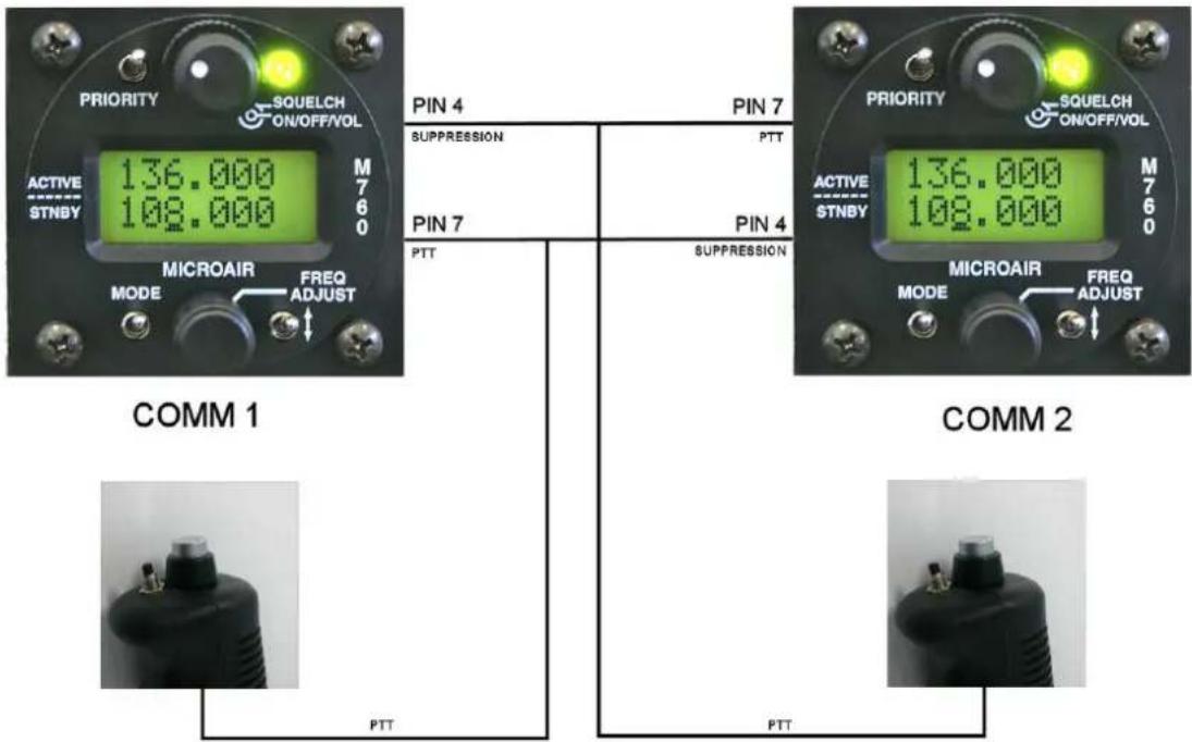

Switching from comm1 to comm2 will move all radio functions including intercom from one radio to the other. Ensure that both radios have the internal VOX intercom set up correctly
3.11 AUXILIARY AUDIO
The M760 Q can accept a line level audio input via pin 6 of the DB15 connector. The volume of this audio can be set by the auxiliary equipment, but will be muted down to a low level when the VOX intercom is triggered, or a signal is received. The auxiliary audio will remain muted for approx 1 second after intercom or receiver activity has finished, before rising again to the set volume.

Do not attempt to feed the speaker output of a car stereo directly into pin 6. The audio level is too high and will damage the audio system of the M760, and void the warranty. Input only line (headphone) level audio.
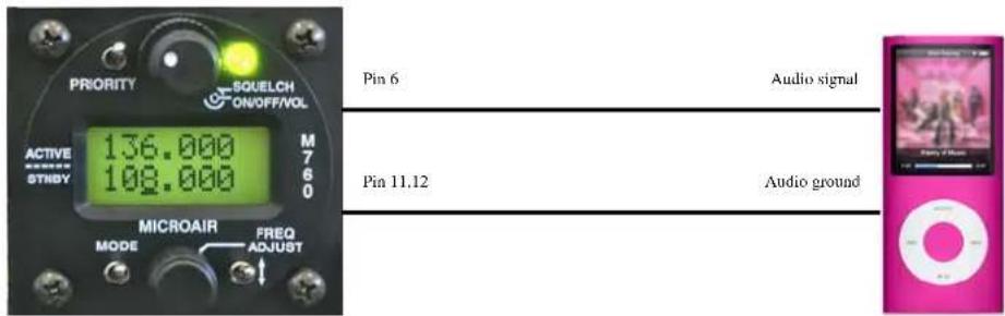
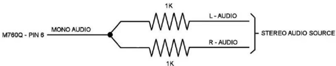
The auxiliary audio input is mono. Most music sources will have a stereo output consistent of left (L) and right (R) audio channels. L and R audios must be combined before connection to pin 6 of the M760Q.
The auxiliary audio can be used to input the altitude alert warnings from the Microair T2000SFL transponder.

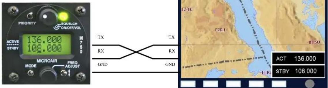
3.12 DATA INTERFACE (SL30)
The M760Q is SL30 compatible, and allows the user to change the active and standby channels from EFIS equipment. The M760Q can also be put in and out of dual monitor mode if the EFIS equipment supports this type of function.
Some types of EFIS equipment do not support SL30 in both directions, ie the user can change channels at the EFIS and the M760 will update, but the user cannot change channels at the radio and have the EFIS update.

The M760Q supports all modes of SL30 except the frequency list upload function. All other SL30 comm commands are supported in both directions.
The SL30 data connection is made via an RS232 data interface:
Pin 2 RS232 RX
Pin 5 RS232 TX
Pin 11,12 Ground
Data Rate: 9600 Baud
8 bit
Parity = none
Stop = 1 bit
Flow = none
The M760 supports the basic SL30 command set for transceiver control.
| SL30 | Command | Description | |
| Input PMR | RV24iiddaRequest for Data Output | ||
| InputPMR | RV29mkaSet Standby Comm Frequency & Function | ||
| Input PMR | RV42mkaSet Active Comm Frequency & Function | ||
| Output | PMRRV20Reset function (M760 ready for data) | ||
| Output | $PMRRV35mkmkasComm Transceiver Status | ||
3.12.1 TRANSCEIVER FUNCTION
In both the set standby and set active commands the “a” field represents the transceiver function:
N = Normal Transceiver receives and transmits on the active.
M = Monitor Transceiver receives on both active and standby, and transmits on active.
0 = Unchanged Transceiver function setting not changed
Hence it is possible for the external equipment (if it supports these commands fully) to change the active and standby frequencies, and switch the M760Q in and out of monitor mode.
3.12.2 TRANSCEIVER STATUS
The Comm Transceiver Status command contains the "a" field for the transceiver's status:
R = Normal receive Normal receiver mode - monitor function inactive
M = Monitor service Monitor function active
T = Transmit enabled PTT button is down - transmitting
S = Stuck mic Transceiver transmitting for longer than 45 seconds
F = Comm failure Transceiver inoperative

IMPORTANT NOTE
After 45 seconds of transmission, the M760Q will flash the red LED TX annunciator. During this period the transceiver status will default to S (stuck mic).
3.13 PC INTERFACE
The M760Q Frequency Compiler software can be used to connect to a PC or laptop with a windows operating system (XP or later version).
The user can quickly compile channel lists and write them to the M760Q. Refer to the Microair Avionics website for full details of the M760 PC application (www.microair.com.au).
3.14 NOISE SUPPRESSION
After installation there may be unwanted noise present in the radio's audio system. There a variety of sources for this noise, but they usually fall into one of two categories:
• Electro-Magnetic Induction (EMI)
• Radio Frequency Induction (RFI)
3.14.1 POWER FILTER
EMI typically affects radio equipment by inducing noise on to the power supply. Microair recommends the installation of a power filter on the power wire to the M760. A simple line filter is sufficient to ensure that the voltage is smooth, and causes no interference to the radio. If engine noise can be heard, and it rises and falls with the RPM, install a power filter.
Refer to the Microair Avionics website www.microair.com.au for more information on aircraft electrical systems.
3.14.2 FERRITE CHOKES
RFI typically affect radio equipment by radiating RF noise into the wiring. The most vulnerable are the microphone, headphone, speaker, and power lines. The instance of RFI can be reduced by installing ferrite chokes on the wiring harness.
Locations for best effect are on the wiring harness immediately behind the DB15 connector at the radio, and on the microphone/headphone lines just behind the headset jacks.


natural_image
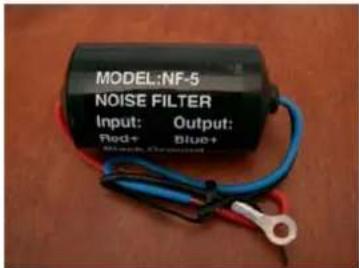
Two black plastic cylindrical objects with cutouts, isolated on white background (no text or symbols)Another form of RFI is the impulse noise from equipment like strobe lighting. This equipment can create large impulses on the power supply which have RF components.
These signals can radiate to adjacent wiring to create noise. The best defence here is a filter capacitor on the power input to this type of equipment. A 0.01uF ceramic capacitor with a 3KV voltage rating is most suitable for this task.

natural_image
Blue cylindrical electronic component with two leads, placed on a wooden surface (no text or symbols visible)Refer to the Microair Avionics website www.microair.com.au for more information on aircraft electrical systems.
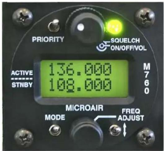
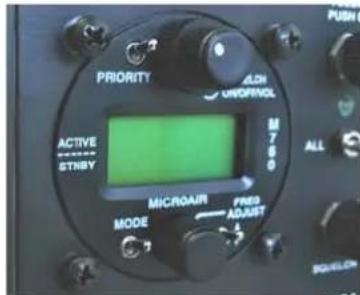
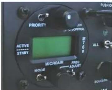
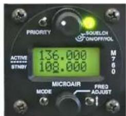
4.0 OPERATIONAL CONTROLS

Front Face Control Column
| ITEM CONTROL DESCRIPTION | ||
| 1 Priority Switch Momentary push down switch | ||
| 2 Volume / On / Squelch Click On - Rotate knob for volumeRotate ring for squelch | ||
| 3 Receiver / Transmit Annunciator Red / Green LED | ||
| 4 Mode Switch Momentary push down switch | ||
| 5 Frequency Adjust Knob Rotate to adjust valuePress to move cursor | ||
| 6 Toggle Switch Momentary push down switch | ||
| 7 Remote Memory Button Momentary push button | ||
| 8 Push to talk (PTT) Button Momentary push button | ||
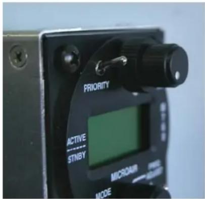
4.1 PRIORITY SWITCH
The priority switch is a push down switch. When pushed down briefly, the radio will go into channel mode, and select the frequency stored in memory 99. Memory 99 should be considered the priority channel, which the user can quickly select when required. Memory 99 must be programmed for the priority switch to operate. Memory 99 is set at the factory as the international distress frequency 121.500MHz. Memory 99 can be programmed the same way as any of the other channels; hence the factory default can be edited. Refer to section 6.5 to edit this memory.
The priority channel (memory 99) can be edited but not be deleted.
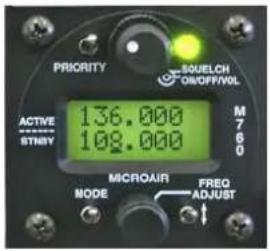
4.2 VOLUME / SQUELCH KNOB
The M760 is turned on, by rotating the volume knob. A positive “click” is heard and felt at the start of the rotation to indicate the on/off position. The volume is increased by rotating the knob clockwise, and decreased by rotating counter clockwise.
The squelch is adjusted by rotating the ring behind the volume knob. There is no automatic level set for the squelch, however the ring affords a large manual adjustment to suit all situations. Rotate the ring clockwise to increase the squelch threshold, and counter clockwise to lower the threshold. When the squelch is “broken” (ie the static hiss can be heard), the annunciator LED lights green.
Note: This does NOT mean you are receiving a signal!
4.3 ANNUNCIATOR LED
The LED operates red or green, and indicates the following states:
Clear (off) Radio is squelched, and is not receiving a signal
Green Squelch is broken or a signal is received
Red Radio is transmitting
Flashing Red Radio has transmitted for over 45 seconds (warning)
The flashing red signal is designed to draw the pilot's attention to the fact that the aircraft may have a stuck PTT button!
Transmissions in excess of 30 seconds should be avoided.
While the M760 is in the program mode menu or memory programming mode the M760 is in its setup state. The radio can not transmit or receive while it is in the setup state.
4.4 MODE SWITCH
The mode switch is a push down switch, which will cycle through the operational modes of the M760. When pushed down briefly the radio will step to the next operating mode.

Press Mode Switch

ACTIVE / STANDBY MODE (Refer section 5.1)
CHANNEL MODE (Refer section 5.3)
VOX ADJUST (Refer section 5.4)

Press Mode Switch

Press Mode Switch
If the internal VOX intercom has been disabled in the program mode menu the intercom adjust mode will be skipped. See section 6.2 to enable / disable the internal VOX intercom.
By holding the mode switch down and turning on, the M760 will start in PROGRAM MENU (refer section 6.0)
4.5 TOGGLE SWITCH
When the toggle switch is pressed briefly in Active/Standby mode, the active and standby frequencies exchange places. Hold the toggle switch down for 3 seconds to activate the monitor function.


- When the M760 is in monitor mode, press the toggle switch briefly to disengage the monitor function.
- When the M760 is in channel mode the toggle switch is used to quick save the frequency.
The toggle switch is also used in the PROGRAM MODE for programming functions.
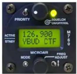
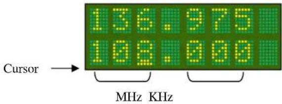
4.6 FREQUENCY ADJUST KNOB
The frequency adjust knob is used to change display values and characters. Rotate the knob to scroll values or characters up or down. Press the frequency adjust knob inwards briefly to move the cursor to the next display item to adjust.
In the active/standby mode, only the standby frequency can be changed directly, the active frequency cannot be directly altered by the frequency adjust knob.
In channel mode the user can scroll alphabetically by turning the frequency adjust knob. The user can scroll alphabetically through stored memory channels, by airport ID (YBUD) and radio service type (CTF).
Refer to section 6.4 for the input and section 6.5 for the amendment of a memory channel.

Channel Frequency
In VOX mode the threshold level can be adjusted up or down by turning the frequency adjust knob.
Adjustment is restricted to values between 1 (mic on continuously) and 42 (very insensitive - shout).


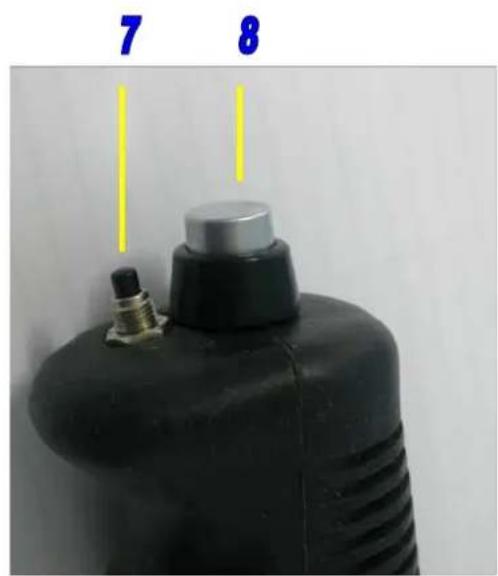
4.7 REMOTE MEMORY BUTTON
If fitted at installation, the remote memory button will have the same functionality as the toggle switch on the display. It will allow the user to toggle (exchange) the active and standby frequencies. The remote memory button is typically mounted next to the PTT on the stick.

If the remote memory button is held down for 3 seconds while in the active / standby mode, the monitor function is activated. Refer to section 5.2 for complete details on monitor function.

In channel mode, press the remote memory button briefly to cycle through the stored memory channels.
When the M760 is in VOX adjust mode, press the remote memory button briefly to increase the VOX threshold.
Remote Memory Button
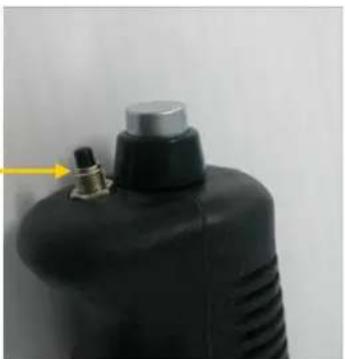
natural_image
Close-up of a black industrial gas cylinder with a metallic top and outlet tube, no visible text or symbols
IMPORTANT NOTE
The remote memory button is highly recommended. It allows the user to keep hands on the controls during flight, while changing channels or mode.
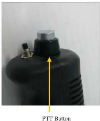
4.8 PUSH TO TALK BUTTON
The push to talk (PTT) button causes the M760 to transmit on the active frequency or selected memory channel. During transmission the LED annunciator will light red and the user will hear themselves speaking through their own headphones via the sidetone system.
The M760 will not transmit if the active frequency or selected memory channel is below 118MHz.
The M760 will not transmit if the CD lockout function is enabled and the M760 is currently receiving a signal. See section 6.1 to enable / disable the CD lockout function.
5.0 OPERATIONAL MODES
The M760 transceiver can operate in several operation modes. The user can step through these modes by pressing the mode switch briefly. Operational modes are:
Active/Standby Mode
Channel Mode
VOX Adjust Mode
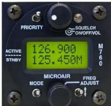
5.1 ACTIVE/STANDBY MODE
The display shows the active or in use frequency on the top line. The standby frequency is displayed on the bottom line. Only signals on the active frequency are received. Transmissions can be made on the active frequency by pressing the PTT button.
The active and standby frequencies are swapped by pressing the remote memory button or the toggle switch. The standby frequency can be changed by scrolling the frequency adjust knob. The cursor can be moved between MHZ and KHZ positions by pressing the frequency adjust knob. Press the mode switch to toggle the display from Active/Standby mode to Memory mode.

5.1.1 108 TO 118 MHZ TUNING
The pilot can select channels in the navigation (NAV) band from 108.000MHz to 117.975 MHz. The M760 will receive only on these channels – the PTT button is disabled.
Many civil aviation authorities are now allocating voice services such as ATIS in the NAV band.

IMPORTANT NOTE
When the active frequency is set below 118.000MHz, the transmitter is disabled.
5.2 MONITOR FUNCTION
By holding down the remote memory button or toggle switch for 3 seconds and then releasing, the M760 will enable the monitor function.
Both active and standby frequencies are monitored at the same time for a signal.
An ‘M’ character will oscillate up and down to indicate that the monitor function is active.
A signal can be received on either the active or the standby frequency. An “R” character will appear beside the channel receiving the signal.
While receiving a signal on the active frequency - the standby channel is NOT monitored.
While receiving a signal on the standby frequency - the active channel is periodically monitored. If a signal is found on the active frequency the M760 will revert to the active frequency.
After a signal has been received the M760 will return to monitoring both frequencies.

IMPORTANT NOTE
The user can only transmit on the active frequency. If the PTT is pressed the radio will transmit on the active frequency only.
Monitor mode can be cancelled by pressing the remote memory button or toggle switch briefly. The 'M' character is no longer displayed at the right hand side of the display.
If the mode switch is pressed to move from active/standby mode to channel mode, the monitor function is disengaged.

Monitor Mode
Monitoring on ACTIVE frequency

Monitor Mode
Monitoring on STANDBY frequency

Monitor Mode
Receiving on ACTIVE frequency

Monitor Mode
Receiving on STANDBY frequency

Monitor Mode
Transmitting on ACTIVE frequency
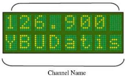
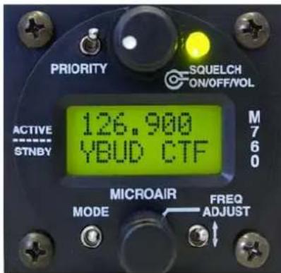
5.3 CHANNEL MODE
The M760 has a memory database which can store up to 99 channels.
Each channel can be programmed with any available frequency from 108.000MHz to 136.975MHz, and is named with a 4 character location and 3 character service description.
Refer to the PROGRAM MODE Menu (sections 6.4 & 6.5) for the programming of memories.
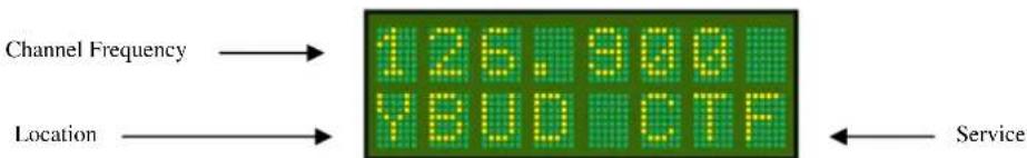
flowchart
graph LR
    A["Channel Frequency"] --> B["126.900"]
    C["Location"] --> D["YBUDCTF"]
    B --> E["Service"]
    D --> E
When operating in channel mode, the programmed channels can be scrolled through alphabetically, by rotating the frequency adjust knob, or by pressing the remote memory button. Only programmed memories are displayed.
When changing operational modes the Active Frequency is carried forward to the next mode to avoid an accidental change in channel.
When the operational mode is changed to channel mode, the M760 will check all memory channels for the current active frequency. If it finds the current active frequency it will display the memory channel that corresponds to the current active frequency. If the current active frequency is not found in any memory channel a '?' will be displayed on the bottom line.

The user can use the frequency adjust knob to scroll alphabetically through the memory channels
5.4 VOX MODE
The M760 has a digitally controlled VOX intercom. VOX stands for “voiced activated”, which means the intercom function will trigger automatically when the user starts speaking into the microphone.
It is important to set the threshold level to trigger on the microphone.
If the level is too low, the microphones will always be on, and the user will hear the cabin noise continuously (hot mic).
If the level is too high, the use will not be able to easily trigger the microphones (shout to activate).
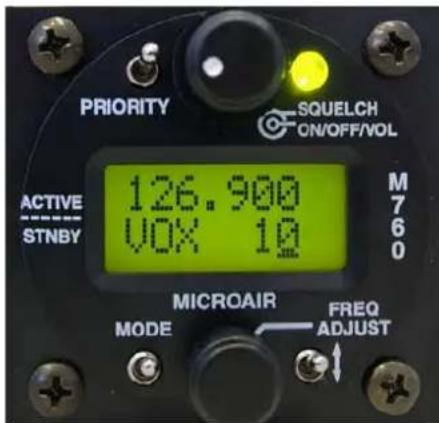
Press the mode switch until the VOX adjust screen is displayed, and set the VOX threshold to the desired level. It may be necessary to readjust this level when the aircraft is operating at full power.
When the VOX is adjusted to 1 the microphones will be on all of the time (hot mic). When the VOX is adjusted to 30+ the microphones will require a very loud voice to activate (shout).


When in VOX mode the active frequency is displayed on the top line.
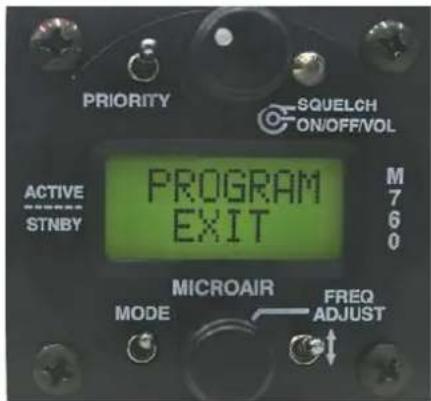
6.0 PROGRAM MENU
The M760 can be started in program mode by holding the mode switch down and turning on. The mode switch must be held down while the display goes through the start-up sequence, and ends with PROGRAM MENU on the display.

Rotate the frequency adjust knob to scroll through the Program Mode Menu items. Use the remote memory button or the toggle switch to select the menu item.
| PROGRAM | MENU | |
| CD | ||
| VOX | ||
| MONITOR | ||
| NEW | MEM | |
| EDIT | MEM | |
| EXIT |
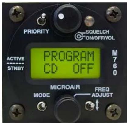
6.1 CD LOCKOUT
When CD Lockout is set ON the M760 will not permit the PTT button to operate if a radio signal is currently being received.
If the user attempts to transmit by pressing the PTT button, the M760 will not transmit.
The signal being received will be heard in the headphones or speaker.
When CD Lockout is set OFF the M760 will permit the PTT to operate if a radio signal is currently being received.
Background:
In high traffic areas such as circuit patterns, there is often a high level of radio traffic. There is also a high instance of two aircraft trying to transmit at the same time. When this occurs the two transmissions interfere with each other, and neither call can be properly received.


The CD Lockout is toggled by pressing the Toggle Switch. The factory default is to have the CD lockout OFF.
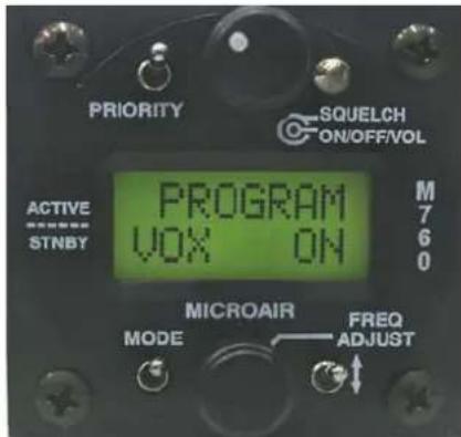
6.2 VOX
When VOX intercom is set ON the M760 user is able to set the threshold of the internal VOX intercom via the intercom adjust screen (See section 5.4).
When VOX setup is set OFF the M760 will set the internal VOX intercom to its maximum threshold and disable the Intercom Adjust screen.
Press the toggle switch to turn the VOX function ON/OFF.

IMPORTANT NOTE
For installation where an external intercom is to be used, the M760's internal VOX intercom MUST be turned OFF.
6.3 MONITOR SETUP
MONITOR setup allows the user to adjust the sample interval of the monitor function, which allows the user to detect radio traffic on both the active and standby frequencies. When receiving a signal on the standby channel, the M760 will sample the active channel regularly for signal. The MON value represents the rate of the sample.
Background:
The M760 can monitor the active and standby frequencies, but priority is given to the active. When a signal is received on the standby frequency the active frequency is sampled to see is there is a signal present.
The M760 will quickly change channels to check the active for signal even if the standby is receiving a signal. The user will perceive this sample action as a small click in the received audio on the standby channel.
If no signal is found the receiver returns to the standby frequency. When a signal is detected on the active frequency, the M760 will lock to the active even if there is a signal present on the standby frequency.

The MONITOR setup can adjust the sample rate by pressing the Toggle Switch to increase the sample rate value. The adjustment is restricted to values between 1 and 9. From 9, the value will revert back to 1. The factory default is an interval of 5.

6.4 NEW MEMORY CHANNEL
This option allows the user to program a new channel into one of 99 memories. The next available memory will automatically be selected.
To load a new channel the user must enter the frequency, location, and service type. The location is typically the airport ID, but the user may enter any 4 character description. The service type can be selected from a list, or the user can enter any 3 character description.
Press the toggle switch briefly to enter the NEW MEM function.

6.4.1 SET FREQUENCY
Using the frequency adjust knob, set the frequency for the selected memory channel. The cursor can be cycled through the MHz and KHz by pressing the frequency adjust knob. Once the frequency is set, press the remote memory button or the toggle switch briefly.

Cycle cursor between MHz, and KHz, by pressing the frequency adjust knob inwards briefly. Rotate the frequency adjust knob to change value.
6.4.2 SET LOCATION
Using the frequency adjust knob, set the name for the selected memory channel. The cursor can be cycled through the character positions by pressing the frequency adjust knob. Once the name is set, press the remote memory button or the toggle switch briefly.

Cycle cursor between character positions, by pressing the frequency adjust knob inwards briefly. Rotate the frequency adjust knob to change the character.
6.4.3 SET SERVICE
Using the frequency adjust knob, select the service type for the frequency / location from the following list options:

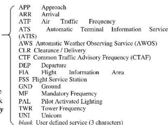

The blank option allows the user to enter a three character service description. Scroll top the blank option and press the frequency adjust knob briefly to access the editing cursor.
Once the service type is selected or entered, press the toggle switch briefly. The word SAVED is displayed, and then the display returns to the Program Menu.
6.5 EDIT MEMORY CHANNEL
The EDIT MEM function allows the user to program a channel in memory. The frequency and airport code stored in each memory channel can be set, changed, or cleared in this mode.
Using the frequency adjust knob, scroll through the existing memories by location in alphabetical order. When the desired memory is displayed, press the toggle switch to edit the details.
Editing is done in the same order as a new memory (refer 6.4).
After editing the M760Q will perform a memory sort to ensure that channels are viewed in alphabetical order. The time taken to do this depends on the number of channels stored in memory (2 minutes for 99 channels).

To delete the displayed memory, press the priority key. The word DELETED is displayed briefly, before the display returns to the program menu.
6.6 EXIT MENU
This option exits the program menu and causes the radio to sort the memory channels before returning to last operational Mode.
Press the toggle switch briefly to exit from the program menu.
If a new memory has been added while operating in the program menu, the M760Q will perform a memory sort to ensure the channels are displayed in alphabetical order. The time taken to do this depends on the number of channels stored in memory (2 minutes for 99 channels).

IMPORTANT NOTE
Do not turn the M760Q off during the memory channel sorting process. The channel will not appear in the correct alphabetical order if the process is interrupted.
7.0 WIRING DIAGRAM

8.0 SPECIFICATIONS M760Q
Radio Type Amplitude Modulation (AM) Aircraft Transceiver
Channels (Transmit) 760 channels, 25KHz spacing 118.000 - 136.975MHz
Channels (Receive) 1160 channels, 25KHz spacing 108.000 - 136.975MHz
Frequency Selection VFO dial
Frequency Display 2 line alpha/numeric LCD display (with backlighting)
Frequency control PLL frequency synthesis, which is microprocessor controlled
Memory is store in non-volatile EPROM
Memories 99 programmable memories
Dual Monitor 100ms Scan Time
User selectable Scan Delay (0.7 seconds to 3.3 seconds)
Power consumption Receive (no signal) 140 mA
Transmit 1.8 A
Input Voltage 10.7 – 16.0 Volts Warning damage will occur above 16 Volts
Power output 5 watts (nominal)
VSWR Tolerance < 2:1 for best operation (5:1 without damage)
Receiver sensitivity 12dB for 0.3 uV 70% modulation (1KHz audio)
Receiver Selectivity -70dB
Squelch Range 0.5 - 10.0uV
Data Interface RS232
Speaker volume output Nominal 4 watts output to 4 ohms
Headset volume output Nominal 100milli-watts output to 600 ohms
Auxiliary Audio Line level audio
Temperature range -20 to +55 degrees Celsius
Stability < +/- 3.00ppm
Dimensions W-65mm H-59mm D-135mm (plus 35mm for harness)
W-2.6" H-2.3" D-5.3" (plus 1.5" for harness)
Exposed dial face 57mm diameter
2 14 " diameter
Weight 416 grams
14.7 ounces
9.0 DRILLING TEMPLATE
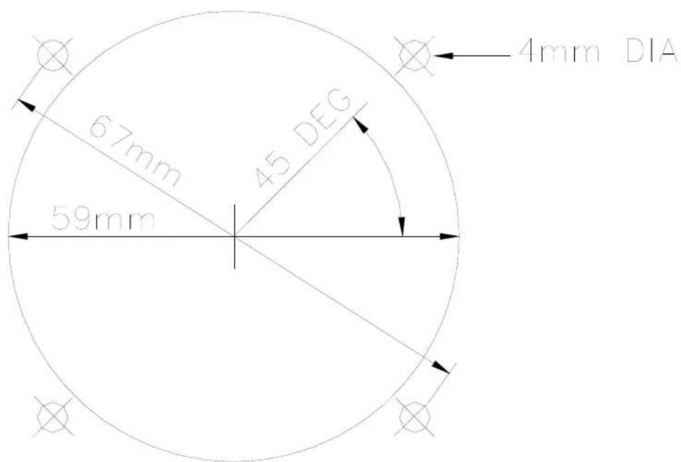
Drilling Template
10.0 LIMITED WARRANTY
The warranty period for any Microair Avionics manufactured article is dependant on Condition of the article at time of sale and the Purchase Date.
For New Articles the warranty period commences from Date of Purchase and is valid for two years or the minimum period defined by applicable consumer law, whichever is the longer. In the absence of original Proof of Purchase the warranty will be valid for two years from Date of Factory Shipment as determined by Microair Avionics.
For Factory Reconditioned Articles offered for sale, the warranty period commences from Date of Purchase and is valid for twelve months.

For Factory Exchanged Articles the warranty period commences from the Date of Purchase of the original article and is valid for the remainder of the original warranty period.
For Repaired Articles the warranty period commences from the date of Factory Shipment and is valid for 6 months for the original defect only.
Microair Avionics will, at its sole discretion, repair or replace any components, which fail in normal use. Such repairs or replacement will be made at no charge to the customer for parts or labour. The customer shall be responsible for any transportation costs for return of this product to Microair Pty Ltd or an approved Microair Service Centre.
This warranty does not cover failures due to abuse, misuse, accident, unauthorised alteration, or repairs carried out by parties other than Microair Avionics or an approved Microair Avionics Service Centre. This warranty does not cover failures where the product has not been installed or operated, in accordance with the provisions of the User and Installation manual(s).
It shall be at Microair Avionics sole discretion to decide if a defect is a result of material or workmanship failure.
THE WARRANTIES AND REMEDIES CONTAINED HEREIN ARE EXCLUSIVE AND IN LIEU OF ALL OTHER WARRANTIES EXPRESSED OR IMPLIED, INCLUDING ANY LIABILITY ARISING UNDER WARRANTY OF MERCHANTABILITY OR FITNESS FOR A PARTICULAR PURPOSE, STATUARY OR OTHERWISE. THIS WARRANTY GIVES YOU SPECIFIC LEGAL RIGHTS, WHICH MAY VARY FROM STATE TO STATE, AND COUNTRY TO COUNTRY.
IN NO EVENT SHALL MICROAIR AVIONICS PTY LTD BE LIABLE FOR ANY INCIDENTAL, SPECIAL, INDIRECT OR CONSEQUENTIAL DAMAGES, WHETHER RESULTING FROM THE USE, MISUSE OR INABILITY TO USE THIS PRODUCT OR FROM DEFECTS IN THE PRODUCT.
Microair Avionics may at it discretion, refer product returns for repair or service, to a service facility closest to you. Microair Avionics reserves the right to repair or replace the product or software or offer a full refund of the purchase price at its sole discretion.
To obtain warranty service, please email or call the Microair Avionics Repair line in Australia.
Domestic or International Return instructions are available on our website. Please follow these instructions carefully.
Phone: ++ 61 7 4155 3048
Fax: ++ 61 7 4155 3049
Email: repair@microair.com.au
Website: www.microair.com.au
Supplied by:


- About This Document
- CURRENT REVISION STATUS
- TABLE OF CONTENTS
- INTRODUCTION....4
- UNPACKING 4
- INSTALLATION....5
- OPERATIONAL CONTROLS....18
- OPERATIONAL MODES....23
- PROGRAM MENU....28
- WIRING DIAGRAM....32
- IFICATIONS M760Q 33
- DRILLING TEMPLATE 34
- TED WARRANTY 35
- INTRODUCTION
- UNPACKING
- USER / INSTALL MANUAL
- IMPORTANT NOTE
- NAMEPLATE DETAILS
- AUTHORISED RELEASE CERTIFICATE
- INSTALLATION
- WIRING
- COAX TERMINATION
- ANTENNA
- METAL SKIN AIRFRAMES
- NON-METAL SKIN AIRFRAMES
- POWER
- BACKLIGHTING
- POWER SAVINGS
- MICROPHONE
- ELECTRET
- DYNAMIC
- SPEAKER
- INTERNAL VOX INTERCOM
- HEADSET ADJUSTMENT
- SIDETONE
- MIC GAIN
- EXTERNAL INTERCOM
- DUAL COMM INSTALLATION
- AUXILIARY AUDIO
- DATA INTERFACE (SL30)
- TRANSCEIVER FUNCTION
- TRANSCEIVER STATUS
- PC INTERFACE
- NOISE SUPPRESSION
- POWER FILTER
- FERRITE CHOKES
- OPERATIONAL CONTROLS
- PRIORITY SWITCH
- VOLUME / SQUELCH KNOB
- ANNUNCIATOR LED
- MODE SWITCH
- TOGGLE SWITCH
- FREQUENCY ADJUST KNOB
- REMOTE MEMORY BUTTON
- PUSH TO TALK BUTTON
- OPERATIONAL MODES
- ACTIVE/STANDBY MODE
- 108 TO 118 MHZ TUNING
- MONITOR FUNCTION
- CHANNEL MODE
- VOX MODE
- PROGRAM MENU
- CD LOCKOUT
- VOX
- MONITOR SETUP
- NEW MEMORY CHANNEL
- SET FREQUENCY
- SET LOCATION
- SET SERVICE
- EDIT MEMORY CHANNEL
- EXIT MENU
- SPECIFICATIONS M760Q
- DRILLING TEMPLATE
- LIMITED WARRANTY
Brand : Microair
Model : M760
Category : Radio transceiver