
CA-1 - Measurement Electronics International - Free user manual and instructions
Find the device manual for free CA-1 Electronics International in PDF.

| Product Type | Digital Multimeter |
| Brand | Electronics International |
| Model | CA-1 |
| Category | Measurement |
| Dimensions (approx.) | 7.0 x 3.5 x 1.5 inches (178 x 89 x 38 mm) |
| Weight (approx.) | 12 oz (340 g) including battery |
| Power Supply | 9V battery (NEDA 1604, 6LF22 or equivalent) |
| Display | LCD, 3-1/2 digits, maximum reading 1999 |
| DC Voltage Range | 200mV, 2V, 20V, 200V, 600V |
| AC Voltage Range | 200V, 600V |
| DC Current Range | 200µA, 2mA, 20mA, 200mA, 10A |
| Resistance Range | 200Ω, 2kΩ, 20kΩ, 200kΩ, 2MΩ |
| Continuity Check | Built-in buzzer (threshold < 30Ω) |
| Diode Test | Yes, forward voltage measurement |
| Overrange Indication | "1" displayed |
| Safety Rating | CAT II 600V |
| Auto Power Off | After approx. 30 minutes of idle |
| Operating Temperature | 0°C to 40°C (32°F to 104°F) |
| Storage Temperature | -10°C to 50°C (14°F to 122°F) |
| Accessories Included | Test leads, 9V battery, manual |
| Maintenance | Wipe with a damp cloth; do not use solvents |
| Spare Parts / Repairability | Replaceable fuses and test leads; battery easily accessible |
Frequently Asked Questions - CA-1 Electronics International
User questions about CA-1 Electronics International
0 question about this device. Answer the ones you know or ask your own.
Ask a new question about this device
Download the instructions for your Measurement in PDF format for free! Find your manual CA-1 - Electronics International and take your electronic device back in hand. On this page are published all the documents necessary for the use of your device. CA-1 by Electronics International.
USER MANUAL CA-1 Electronics International
Single and Multi-Channel
0906941
EGT, CHT, Carb Temp and OAT Instruments
Operating and Installation Instructions
OII 0906941
9/6/94
You must read this manual before installing or operating the instrument. This manual contains warranty and other information that may affect your decision to install this product and/or the safety of your aircraft.


(This manual covers 25 instruments and remote switches)
(Supersedes OI 070781, II 070781, OI 040831 and II 070781-1)
(FAA Approved)
S/N:

Electronics International Inc.®
63296 Powell Butte Hwy • Bend, OR 97701 • (541) 318-6060 • Buy-EI.com

Important Installation Information ^0720921
All steps must be read before installing a probe.
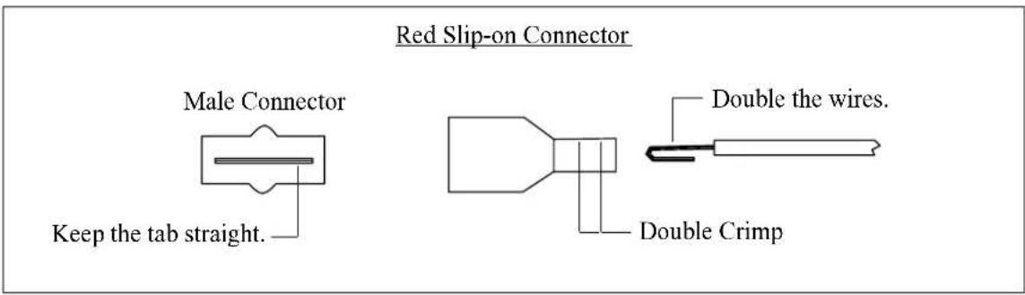
Male Conn.
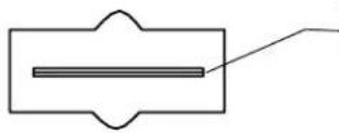
- The tab inside the male connector must be centered (not bent up or down) to mate properly. Check each connector before installation. Two drops of oil on the connector will protect it from corrosion for many years.

-
If you remove a connector, double over the wire before installing it into a new connector. Each connector must be double crimped very tightly.
-
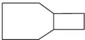
If connectors have been disconnected several times the female connector may become loose. If this happens use a pair of needle nose pliers to retighten the female receptacle then mate the connectors.
Important Notice
\*\*\*\*\* MUST READ \*\*\*\*\*
If you think it is not important to read this manual, you're wrong! This manual contains important installation information that may affect the safety of your aircraft, delay your installation or affect the operation of your instrument. You Must read this manual prior to installing your instrument. Any deviation from these installation instructions is the sole responsibility of the installer/pilot and may render the STC invalid.
Read the Warranty / Agreement. There is information in the Warranty / Agreement that may alter your decision to install this product. If you do not accept the terms of the Warranty / Agreement, do not install this product. This product may be returned for a refund. Contact Electronics International inc. for details.
Check that the instrument make and model marked on the side of the instrument and on the invoice are correct before starting the installation.
It is possible for any instrument to fail thereby displaying inaccurate high, low or jumpy readings. Therefore, you must be able to recognize an instrument failure and you must be proficient in operating your aircraft safely in spite of an instrument failure. If you do not have this knowledge, contact the FAA or a local flight instructor for training.
The pilot must understand the operation of this product before flying the aircraft. Do not allow anyone to operate the aircraft that does not know the operation of this product. Keep the Operating Manual in the aircraft at all times.
Contents
Warranty 2
Operating Instructions: 3
Features 3
EGT's 4
CHT's 7
Carburetor Temperature 8
Outside Air Temperature 8
Installation Instructions: 9
-
Important Information and Initial Check Out 9
-
CHT Probe Installation 10
-
EGT Probe Installation 10
-
Carb. Temp. Probe Installation 10
-
OAT Probe Installation 11
-
Route the Extension Cables 11
-
Hook Up Connecting Wires 13
-
Connect and Install the Instrument and/or Remote Switch 13
-
System Ground Test 13
Troubleshooting Suggestions 14
-
Instrument Check Out 14
-
Probe Check Out 14
-
Extension Cable Check Out 14
Specifications and Operating Features 16
Instrument Wiring Diagram 17
Remote Switch Diagram (RS-4-1, RS-4-2, RS-6-1, and RS-6-2) 18
Remote Switch Diagram (RS-8-1 and RS-12-1) 19
STC Information 20
Warranty / Agreement
Electronics International Inc. warrants this instrument and system components to be free from defects in materials and workmanship for a period of one year from the user invoice date. Electronics International Inc. will repair or replace any item under the terms of this Warranty provided the item is returned to the factory prepaid.
- This Warranty shall not apply to any product that has been repaired or altered by any person other than Electronics International Inc., or that has been subjected to misuse, accident, incorrect wiring, negligence, improper or unprofessional assembly or improper installation by any person. This warranty does not cover any reimbursement for any person's time for installation, removal, assembly or repair. Electronics International retains the right to determine the reason or cause for warranty repair.
- This warranty does not extend to any machine, vehicle, boat, aircraft or any other device to which the Electronics International Inc. product may be connected, attached, interconnected or used in conjunction with in any way.
- The obligation assumed by Electronics International Inc. under this warranty is limited to repair, replacement or refund of the product, at the sole discretion of Electronics International Inc.
- Electronics International Inc. is not liable for expenses incurred by the customer or installer due to factory updates, modifications, improvements, upgrades, changes, or any other alterations to the product that may affect the form, fit, function or operation of the product.
- Personal injury or property damage do to misinterpretation or lack of understanding this product is solely the pilots responsibility. The pilot must understand the operation of this product before flying the aircraft. Do not allow anyone to operate the aircraft that does not know the operation of this product. Keep the Operating Manual in the aircraft at all times.
- E. I. Inc. is not responsible for shipping charges or damages incurred under this Warranty.
- No representative is authorized to assume any other liability for Electronics International Inc. in connection with the sale of Electronics International Inc. products.
- If you do not agree to and accept the terms of this warranty, you may return the product for a refund.
This Warranty is made only to the original user. THIS WARRANTY IS IN LIEU OF ALL OTHER WARRANTIES OR OBLIGATIONS: EXPRESS OR IMPLIED. MANUFACTURER EXPRESSLY DISCLAIMS ALL IMPLIED WARRANTIES OF MERCHANTABILITY OR FITNESS FOR A PARTICULAR PURPOSE. PURCHASER AGREES THAT IN NO EVENT SHALL MANUFACTURER BE LIABLE FOR SPECIAL, INCIDENTAL OR CONSEQUENTIAL DAMAGES, INCLUDING LOST PROFITS OR LOSS OF USE OR OTHER ECONOMIC LOSS. EXCEPT AS EXPRESSLY PROVIDED HEREIN, MANUFACTURER DISCLAIMS ALL OTHER LIABILITY TO PURCHASER OR ANY OTHER PERSON IN CONNECTION WITH THE USE OR PERFORMANCE OF MANUFACTURER'S PRODUCTS, INCLUDING SPECIFICALLY LIABILITY IN TORT.
OPERATING INSTRUCTIONS
Features
1. Instruments:
The Electronics International line of single and multi-channel instruments offer the following features:
A. Digital Display - The digital display allows you to read absolute temperatures at a glance. It does not require interpretation of dials or tic marks. In a short period of time you will be come familiar with the normal operating temperatures of your engine. Abnormal temperatures will be easy to spot. The digital display is easily viewable in direct sunlight. If the instrument backlight has been permanently powered up (as recommended), the digital display will be easier to see during low ambient light conditions and at night.
B. 1 Degree Resolution - The digital display resolves temperatures to 1 degree. This allows you to interpret trends quickly. This can be very helpful in diagnosing problems and leaning your engine. Also, any unit may be ordered to display in degrees F or degrees C.
C. 1/2% Accuracy - Electronics International instruments are not affected by shake, shock, vibration, tilt, stick-slip, bearing wear, spring wear, lead resistance, probe resistance, magnetic fields or the many other factors that plague analog instrument accuracy. All E.I. instruments are temperature compensated to read cabin temperature when a probe is disconnected. E.I. instruments should never need recalibration. Carburetor and outside air temperatures are measured on precision channels. If a non-precision channel (i.e., EGT, CHT, etc.) is used to measure Carb. Temp or OAT there can be a several degree temperature error. A precision channel uses a single yellow connector.
D. Flexibility - Electronics International instruments are compatible with any type K ungrounded probe. This means any instrument, regardless of what is printed on the front panel (EGT, CHT, OAT, etc.), will work with any of our probes (i.e., an OAT channel can read EGT or CHT probes accurately). Also, lead resistance does not affect the accuracy of these units. You may use any length extension cable between the unit and the probe without affecting the accuracy of the instrument.
E. Upgradable - Any single channel EGT and/or CHT unit may be upgraded to a full multi-channel analyzer by simply adding a remote switch to the system. The instruments, remote switches, extension cables and probes were designed in a modular fashion with slip-on connectors. This means a remote switch may be added to your existing system by simply mounting it into your instrument panel, installing the additional wires and probes and plugging it in. You do not have to buy a new system to upgrade to a full analyzer.
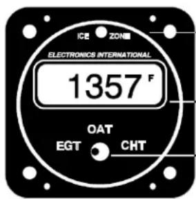
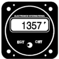
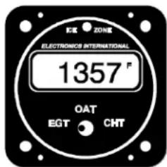
Ice Zone Warning Light. Only available on the Carb. Temp/OAT instruments.
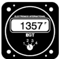
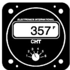
Digital Display.
Selector Switch.
2. Remote Switches:
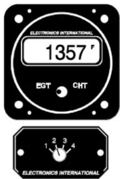
Instrument displaying EGT for channel #2.
A remote switch may be connected to any channel on any Electronics International Instrument. This gives the instrument multi-channel capability. There are two types of remote switches available, single deck and double deck. If a single deck four channel remote switch (RS-4-1) is connected to the EGT channel on an EC-1, the instrument would be capable of measuring four EGT's and one CHT. The remote switch will select which EGT channel would be displayed on the EC-1 instrument when the instruments selector switch is placed in the EGT position. If a double deck four channel remote switch (RS-4-2) is connected to the EGT and CHT channels on an EC-1, the instrument will be capable of measuring four EGT's and four CHT's. The EC-1 will select whether EGT or CHT will be displayed. The Remote Switch will select which channel will be displayed.
EGT's
1. Leaning:
You will want to lean your engine in cruise. A rich running engine wastes fuel needlessly and tends to run rough. This creates vibration, which causes deterioration of engine accessories and engine mounts. Also, proper leaning at cruise and during descent means less spark plug fouling, longer life for the plugs, reduced maintenance costs and considerable fuel savings. Furthermore, good leaning techniques result in cleaner combustion chambers with fewer lead salt deposits on the pistons and exhaust valves. Under certain conditions, these deposits invite preignition and higher maintenance costs. Proper leaning at cruise during cool or cold weather aids in raising engine and oil temperatures to desirable minimums in order to evaporate the water and acids out of the oil. Water and acids attack the insides of an engine, causing rust and corrosion.
To properly lean your engine using a multi-channel analyzer perform the following steps:
A. Rough Leaning: Select the hottest EGT cylinder. Adjust the mixture control from the full rich position to a leaner setting that results in a slight drop in engine RPM or to a setting near peak EGT, as dictated by experience. The mixture control should be left at this setting until the EGT's stabilize. It will take about 20 seconds for the temperatures to stabilize within 1'F. This lag is due to the combustion walls and piston domes increasing in temperature, which affect the combustion and exhaust gas temperatures. To correctly lean an engine you must wait for the engine to thermally stabilize. Less sensitive gauges will not pick up these subtle changes, which are important in leaning and diagnosing problems.
B. Precision Leaning: Again select the hottest EGT cylinder. This cylinder may be different than the one you started with. This is the cylinder on which you should perform your precision leaning. Again, start leaning, making only very small adjustments and waiting 3 to 5 seconds between adjustments. As
you approach peak, the exhaust gas temperature will rise much slower until it starts to decrease. When this happens you have reached peak EGT. The 1`F resolution of the digital display will be invaluable in helping you precisely detect peak EGT.
C. Finding The Cylinder That Peaks First: For most engines Step B (Precision Leaning) will result in a properly leaned engine. If you find this to be the case with your engine, this step will not be necessary. But if you want to verify that you have leaned to the cylinder that peaked first and your engine is operating properly, perform the following with the cylinder found in step B at peak EGT. Slightly enrich the mixture and quickly step through each cylinder. Any cylinder that shows a rising temperature is a leaner cylinder. Check that this cylinder does not rise more than 15°F before it starts decreasing in temperature. If a cylinder rises more than 15°F it may have a problem.
When installing a single channel EGT instrument in an aircraft there is no guarantee that the probe is installed on the leanest cylinder. Every engine operates a little differently. For the same make and model of engine installed in the same type of aircraft there can be differences between the leanest cylinders. Furthermore, there can be a difference between operating temperatures and the temperature spread between cylinders. Every engine has its own unique operating temperatures. To properly lean your engine using a single channel EGT unit perform the following steps:
A. Rough Leaning: Adjust the mixture control from the full rich position to a leaner setting that results in a slight drop in engine RPM or to a setting near peak EGT, as dictated by experience. The mixture control should be left at this setting until the EGT's stabilize. It will take about 20 seconds for the temperatures to stabilize within 1'F. This lag is due to the combustion walls and piston domes increasing in temperature and, therefore, affecting the combustion and exhaust gas temperatures. To correctly lean an engine you must wait for the engine to thermally stabilize. Less sensitive gauges will not pick up these subtle changes, which are important in leaning and diagnosing problems.
B. Precision Leaning: Again, start leaning, making only very small adjustments and waiting 3 to 5 seconds between adjustments. As you approach peak the exhaust gas temperature will rise much slower until it starts to decrease. When this happens you have reached peak EGT. The 1'F resolution of the digital display will be invaluable in helping you precisely detect peak EGT. You will then need to enrich the mixture for an EGT reading 30'F lower than peak to insure there is no cylinder operating on the lean side of peak EGT.
If your engine runs rough before peak EGT is reached, note the temperature reading on the EGT instrument. When an engine starts to run rough (not when it loses power, but actually runs rough) the leanest cylinder has gone past peak EGT by 30 to 50 degrees F. The leanest cylinder is lean misfiring causing the engine to run rough. From this point enrichen the mixture to obtain a 50 degrees F lower EGT from the noted temperature. This will set the leanest cylinder slightly on the rich side of peak EGT. The rest of the cylinders will be running richer than the leanest by an amount dictated by the temperature spread for your engine. With this method you can reasonably lean an engine even when the probe has not been mounted on the leanest cylinder.
Electronics International's unique stable display allows you to precisely lean to peak EGT or to a specific temperature below peak for most engines. Peak EGT with a float-type carbureted engine is frequently a vague point because of the fuel/air distribution issues in these lower horsepower engines. As a result, these
engines tend to operate smoother at 25^ F on the rich side of peak EGT. Fuel-injected engines will provide a more precise peak. Most engines normally operate within an EGT range of 1300^ F to 1600^ F at cruise power.
Some engine manufacturers allow leaning to peak EGT at 75% power and below on their direct drive normally aspirated engines. For your engine, check the engine manufacturer's recommended procedures. It is not recommended to lean to peak EGT above 75% power settings. The richer mixture is needed to cool the combustion temperatures and keep the anti-knock capability of the fuel high enough to prevent detonation from occurring at the higher power settings.
2. EGT Diagnostics:
Since the EGT is directly related to the combustion temperature, it is an indication of the engine's ability to produce power. If the engine is not producing the correct amount of power, the EGT instrument can be a very valuable troubleshooting tool as well as early warning system before engine failure occurs. With 1°F resolution, our digital EGT instruments will react to the slightest changes in the combustion process. To detect a problem, become familiar with your engine's normal EGT readings during run-up, climb, cruise and descent. Any difference from the norm can be a sign of trouble.
During normal operation the EGT will stabilize to 1'F for a given throttle and mixture setting. If it does not stabilize, this can also be the first sign of trouble. With rate and trend information being displayed instantaneously and with temperatures being read to 1'F, few problems can escape the pilot flying one of Electronics International's analyzer systems. The following is a list of EGT/CHT symptoms and possible problems:
Symptom
| One EGT reads abnormally high. The corresponding CHT reads lower than normal. | — Burned valve or broken ring, defective plug, plug wire or mag. |
| One EGT reads abnormally high. The corresponding CHT reads higher than normal. | — Plugged injector, intake leak. |
| One EGT reads abnormally low. | — Over-sized injector, restricted exhaust, broken or leaky exhaust header. |
| High CHT's and/or high EGT's on all cylinders. | — Excessive leaning with power settings over 75%. Detonation due to bad fuel. Closed or restricted cowl flaps. Missing or loose baffling. |
| High EGT's and/or low CHT's on all channels. | — Timing problem or defective mag. |
| Jumpy readings on one channel. | — This is not an engine problem. Check all connections and the probe for proper operation. See Troubleshooting Section of this manual. |
It is not necessary to continually monitor the EGT's in order to detect a problem. Most problems worsen over a period of time and can be easily detected before they become a safety hazard by thoroughly checking the EGT readings at run-up and once or twice during a flight.
CHT's
1. CHT Operation:
The Cylinder Head Temperature (CHT) instrument helps the pilot protect his engine against the threat of excessive heat. Most general aviation aircraft monitor the hottest CHT, as determined by extensive flight tests done by the airframe manufacture. Minimum in-flight CHT should be 150°F, and maximum in most direct drive normally aspirated Avco Lycoming engines is 500°F. Some of the higher powered, more complex engines have a limit of 475°F. Although these are minimum and maximum limits, the pilot should operate the engine at more reasonable temperatures in order to achieve the expected overhaul life of the powerplant. It would be normal during all-year operations in climb and cruise to see cylinder head temperatures in the range of 350°F to 435°F.
Sudden cooling of the CHT (known as shock cooling) is a problem that is common with aircraft engines. This is caused by fast descents with little or no power and rich mixtures. This may result in bent pushrods due to exhaust valves sticking, burned valves, spark plug fouling, broken piston rings, cracked cylinders at the spark plug and valve ports and warped exhaust valves. To avoid these problems, do not allow the CHT to cool more rapidly than 1°F every 3 seconds during in-flight operation. This can be easily detected with our 1°F digital display.
During climbs, the cylinder head temperatures will rise rapidly until the heat absorbed by the combustion walls is dissipated out the engine's cooling fins. At this point, the CHT will stabilize. Any change in throttle, mixture, cowl or airspeed will affect the CHT and the rate at which it will change. Since rate and trend information can be easily interpreted from our digital display, changing any one of these parameters to stabilize, slow or reduce the CHT is possible with almost immediate results. Our digital instrument takes the guesswork out of controlling your CHT.
2. CHT Diagnostics:
The source of heat in an engine is from the combustion of the fuel/air mixture producing temperatures of approximately 4000°F. Some of this heat energy goes into heating the cylinder heads through radiation and conduction. This heat is sinked away from the engine by the air flow over the cylinder heads. When the heat being generated in the cylinder heads equalizes with the heat being sinked away, the cylinder head temperature will stabilize. If a problem arises in the combustion chamber or in the ability of the cooling system to sink away heat, the CHT's will be affected. To detect a problem, become familiar with your engine's CHT operating temperatures during run-up, climb, cruise and descent. Any differences from normal can be a sign of trouble.
Continuous change in the CHT can also be a sign of trouble. Because of the large thermal mass of the engine, the CHT's change slowly after the initial climb. Any continuous change in one or all of the CHT's after this initial climb can be the sign of trouble. The rate and trend of this change can easily be detected with Electronics International's 1'F resolution digital display. This information allows the pilot to make changes in flight attitude or engine operation and see the effects almost instantaneously.
Carburetor Temperature
Venturi affect and atomization of fuel can cause temperatures in the carburetor to drop 30°F or more. When the atmospheric conditions are right for the aircrafts' current flight altitude (moderate to high humidity), the moisture in the carburetor venturi can freeze quickly. Within minutes ice can choke off the venturi and the engine will stop with little warning.
When Carb. Temp. is selected on the Electronics International Carb. Temp. instrument, the carburetor temperature is continuously monitored and the “Ice Zone” warning light over the display is activated for that channel. The “Ice Zone” warning light is only active for the channel selected. At 39°F (before ice can form in the venturi of the carburetor) the “Ice Zone” warning light will light up. When this happens, apply carburetor heat, making small adjustments to bring the carburetor temperature above 39°F, thereby avoiding any possible carburetor icing condition. An additional benefit of running carburetor temperatures 9°F above freezing is improved atomization of the fuel which results in fewer lead deposits, cleaner plugs and better economy. If the carburetor temperature is below 10°F the “Ice Zone” warning light will go off. Below 10°F there is not enough moisture in the air to form ice in the carburetor.
The “Ice Zone” warning light has the advantage of catching your attention without having to continuously monitor the unit. At night this light may be too bright. An LED Intensity Control Line is provided which may be connected to the aircraft panel rheostat. When the instrument panel lights are turned up the “Ice Zone” warning light will dim.
Monitoring carburetor temperature to 1°F can also help with hard to start engines. If the engine becomes flooded and fuel starts to drip from the carburetor, the unit will display a drop in carburetor temperature as the fuel starts to evaporate. If the engine backfires and a fire starts in the venturi, the unit will display a rapid rise in the carburetor temperature. The carburetor probe is rated for 700°F, so probe damage is not likely.
Outside Air Temperature
The Electronics International OAT instrument has three features that make it a valuable tool when measuring outside air temperatures. The first of these features is its superior accuracy and linearity over conventional gauges. Outside air temperatures have a big affect on your aircraft's ability to lift and on engine horsepower. Accurate OAT readings are essential if you are looking for maximum performance from your aircraft.
The second valuable feature is the instrument's ability to detect small temperature changes (1'F). This gives the pilot rate and trend information (in what direction and how fast the temperatures are changing) at a glance. This is valuable for detecting changing atmospheric conditions and avoiding thunderstorms and icing conditions. It can also help to find cooler flying conditions in warm weather.
The third feature is the instrument's Ice Zone Warning Light. This light will come on when the OAT drops to 39°F and stays above 10°F. This feature can be very useful to a pilot by warning him of the possibility of structural ice if weather conditions are right.
The Electronics International OAT instrument resolves outside air temperatures to 1'F and is very sensitive to air temperatures changes. For this reason, when the OAT probe is in still air and near a heat source, such as hot asphalt, a hangar heater, etc., the unit will read the actual temperature to which the probe is subjected. When the engine starts and there is a flow to air over the probe, the unit will read the air temperature accurately and display changes quickly.
INSTALLATION INSTRUCTIONS
1. Important Information and Initial Check Out:
A. The installer and aircraft owner must read the Warranty before starting the installation. There is information in the Warranty that may alter your decision to install this instrument. If you do not accept the terms of the Warranty, do not install this instrument.
B. If you are not an FAA Certified Aircraft Mechanic familiar with the issues of installing aircraft EGT, CHT, Carb Temp and/or OAT instruments, Do Not attempt to install this instrument. The installer should use current aircraft standards and practices to install this instrument (refer to AC 43.13).
C. Check that any necessary FAA Approvals (STC's, etc.) are available for your aircraft before starting the installation. STC's are located at the back of this manual.
D. Read the entire Installation Instructions and resolve any issues you may have before starting the installation. This may eliminate any delays once the installation is started.
E. THIS INSTALLATION MAY REQUIRE SOME PARTS UNIQUE TO YOUR AIRCRAFT THAT ARE NOT SUPPLIED IN THE KIT. Acquire all the parts necessary to install this instrument before starting the installation.
F. Check that the instrument make and model are correct before starting the installation.
G. Before starting the installation make sure the unit will fit in the location you intend to install it without obstructing the operation of any controls.
H. If this instrument is to replace an existing unit in the aircraft, it is the installer's responsibility to move or replace any existing instruments or components in accordance with FAA approved methods and procedures. The following Installation Instructions do not cover moving or the removal of any existing instruments or components.
2. CHT Probe Installation:
A single CHT probe should be placed on the hottest cylinder. In a 6-cylinder engine this would be one of the center cylinders. On a 4-cylinder engine this would be one of the back cylinders.
If a second CHT probe is to be installed it should be placed on one of the front unobstructed cylinders. This will allow the unit to detect shock-cooling.
Most engines have a port just below the lower spark plug for the CHT probe. If your engine has a primary CHT probe in one of the cylinders, do not remove it. Select another cylinder for your probe. If you're putting a CHT probe on every cylinder use our P-102 Gasket CHT Probe for secondary readings on your primary cylinder.
3. EGT Probe Installation:
A single EGT probe should be installed in the exhaust stack of the leanest cylinder. Each engine has its own characteristics and the leanest cylinder can be different from aircraft to aircraft. As a general rule, the leanest cylinder is one of the back cylinders on a carbureted engine and one of the center cylinders on a fuel-injected engine.
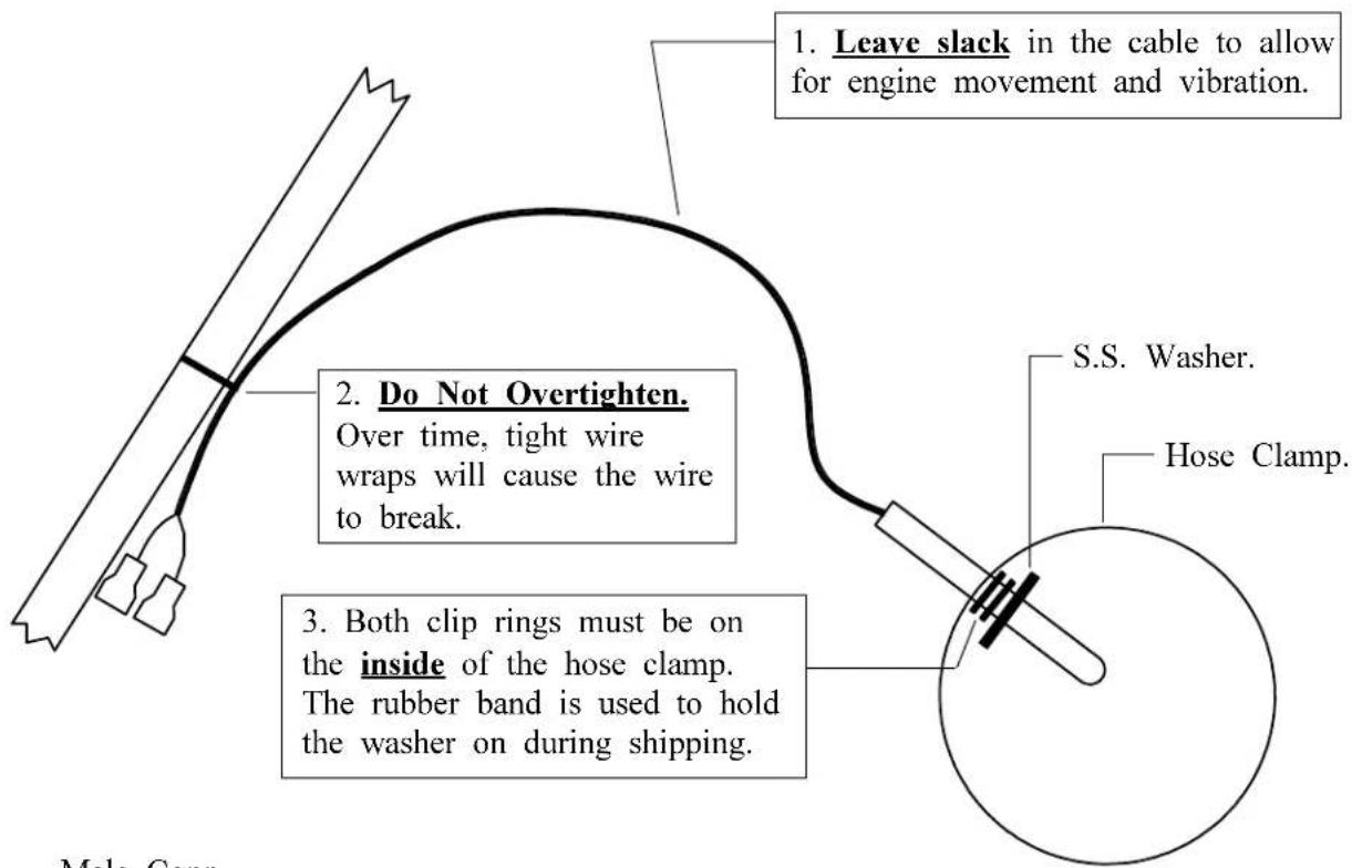
Look at each exhaust stack and determine the best location at which all of the EGT probes can be mounted at the same distance down from the exhaust ports. The ideal location is 1 1/2", but ease of installation should prevail. Drill a 13/64" diameter hole in each exhaust stack. Insert the probe and tighten the hose clamp. As the hose clamp is heated and cooled, it will become loose as it conforms to the exhaust stack. After the first 10 hours of operation, each hose clamp should be retightened.
IMPORTANT NOTE: For Cessna 210's or any aircraft using a slip joint in the exhaust system, install the EGT probes ABOVE OR BELOW THE SLIP JOINT. Installing a EGT probe in the slip joint can damage the probe.
4. Carb Temp Probe Installation:
Remove the threaded plug located in the carburetor housing just below the throttle valve. Install the Carburetor Temperature Probe in this hole using a lock washer. Care should be taken not to over-tighten the probe and strip the threads in the carburetor housing.
If your carburetor does not have a factory tapped hole, remove the carburetor from the engine. Drill out the lead plug located just below the throttle valve with a 7/32 drill and tap this hole with a 1/4 x 28 tap. Remove all burrs and metal shavings from the interior and exterior of the carburetor. Install the carburetor temperature probe as outlined above. Reinstall the carburetor on the engine.
NOTE: A Carb Temp Probe should be connected to the precision channel on a CA-1, A-1 or EAC-1 unit. A three to four degree F error can occur in some instances if the Carburetor Probe is not connected to a precision channel.
5. OAT Probe Installation:
Mount the OAT Probe in an appropriate location on the aircraft, using the hardware supplied. The OAT Probe is sensitive to air temperature changes. For this reason, do not mount the OAT probe in the path of the cowl or engine exiting air (i.e., on the belly of the aircraft). Also, the probe should not be mounted within 8 inches of an exhaust pipe. The radiant energy from the exhaust pipe can cause the probe to read slightly high. Other than these considerations the OAT Probe may be mounted in an air intake vent, on the side of the cowling or anywhere else on the aircraft.
NOTE: An OAT Probe should be connected to the precision channel on a CA-1, A-1 or EAC-1 unit. A three to four degree F error can occur in some instances if the OAT Probe is not connected to a precision channel.
6. Route the Extension Cables:
Mark both ends of each cable with the appropriate cylinder and/or probe type. Plug each probe into its associated extension cable. Be sure the connectors mate properly. When tie wrapping these cables down, be sure there is no strain or pulling on the cable against the probe housing. Each probe should have 3 to 4 inches of slack to allow the engine to move in its mount without breaking any wires. Also, there should be a tie wrap near the probe connectors. Dress each cable up to the instrument or remote switch keeping them away from any hot areas (exhaust stacks, cylinder heads, etc.).
We do not recommend removing the connectors when installing the extension cables but if you must shorten the cable, pull any excess cable length through the fire wall and cut it off at this time. However, it is recommended you leave some extra wire length under the instrument panel for later modifications. Varying cable lengths will not affect the accuracy of this instrument so cables of any length may be ordered from the factory. The Extension Cables and probe wires are made of type K thermocouple wire that must not be substituted or extended with regular copper wire. Also, it is important these wires not be kinked (i.e., do not bend the wires on a radius less than 1 inch).
Attach the appropriate connectors to the ends of each of the Extension Cables as described below:
Red Slip-on Connectors
A) Strip the overbraid back 3 1/2". Be careful not to nick the wires.
B) Shrink a piece of 1" heat shrink over the cut portion of the overbraid.
C) Split the two wires back 3". Be careful not to nick the wires.
D) Strip each wire and double the wires over. These wires must be doubled over.
E) Place a male connector on the red wire and a female connector on the yellow wire. Double crimp these connectors. A good crimp is very important. Poor crimps will cause jumpy readings and are the biggest source of problems.
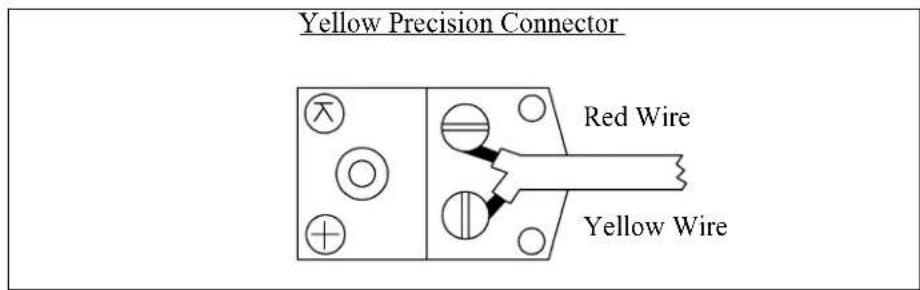
Yellow Precision Connector
A) Strip the overbraid back 3 1/2". Be careful not to nick the wires. Shrink a piece of 1" heat shrink over the cut portion of the overbraid.
B) Remove the yellow cap on the Precision Female Connector.
C) Strip back the wire insulation 1/2".
D) Connect the yellow lead of the Extension Cable to the terminal marked “+” and the red lead to the other terminal. The insulation on these wires should almost touch the mounting screws. Replace the yellow cap on the Female Precision Connector. Be careful not to overtighten any screws or twist the wires when installing the connector.
Tie off any excess cable under the instrument panel. Be sure these cables do not obstruct the freedom of travel of any controls. Cable length does not affect the accuracy of our units, so cables of any length may be ordered from the factory.
7. Hook-Up Connecting Wires:
Connect the red wire supplied in the kit to the 12 or 24 volt bus via a 1 amp fuse or circuit breaker (see the Wiring Diagram at the back of this manual). Connect the black wire supplied in the kit to ground. Connect the white/violet to the 12V bus (leave it open for a 24V system). Connect the white/gray wire to the 24V bus (connect to ground for a 12V system). If this unit has an "Ice Zone" warning light, connect the white/orange wire to the Panel Light Rheostat to dim the "Ice Zone" warning light at night.
Tie off any excess cable under the instrument panel. Be sure these cables do not obstruct the freedom of travel of any controls.
8. Connect and Install the Instrument and/or Remote Switch:
Connect the extension cables and all other wires to the instrument and/or remote switch as shown in the appropriate wiring instructions at the back of this manual. Be sure the connectors mate properly. Install the unit from behind the instrument panel using 6 x 32 screws. These screws must not be longer than .4 inches. Install the remote switch through a 1" square hole cut into the aircraft instrument panel. Tie wrap cables as needed. Be sure these cables do not obstruct the freedom of travel of any controls.
9. System Ground Test:
A. Turn the master switch on and look for a near ambient temperature reading on each channel. If the instrument does not power-up (display a reading), check the power and ground leads (red and black leads) for an open, loose or poor connection.
If you suspect any channel is not receiving a signal remove the probe from the engine (leaving it connected to the Extension Cable) and apply a temperature to it. Look for an increase in reading on the display for that channel. Check the other channels for an increase in reading. You may have connected the probe to the wrong Extension Cable. If the reading is decreasing, you may have reversed the connectors on the Extension Cable leads (the yellow wire on the probe must connect to the yellow wire on the Extension Cable).
B. Start the engine and check each channel for a proper reading. On the ground EGT's will read around 900'F and CHT's will read around 200'F. If you suspect any channel is not receiving a signal properly, see the "Troubleshooting" section of this manual.
Because high reliability is designed into Electronics International's equipment, there is no reason to put up with poor operation. We have few problems with our probes, cables and units and installation is simple. Usually fixing a problem is just a matter of inspecting the installation at a few key points.
Strategy:
If you have more than one problem, FIX ONE PROBLEM AT A TIME. Trying to fix all of them at once can be confusing and misleading. In many cases fixing one problem first will lead you to the solution for fixing all of the problems. Therefore, take one problem on one channel and proceed with the following:
1. Instrument Check Out:
If there is an identical symptom on each channel, then the instrument may have a problem. But if even one channel of the instrument is operating properly, the instrument probably does not have a problem. A good method to test the instrument is to remove all the Extension Cables. Then look for a reading on all channels to be near cabin temperature. The only inputs a unit requires to operate properly and measure cabin temperature is power (red lead) and ground (black lead). Check the power and ground leads for proper connection (pull on the wire at each connector).
NOTE: Few problems turn out to be the instrument.
2. Probe Check Out:
There are two good methods of testing a probe. Perform one or both of the following:
A. A probe can be tested with an ohmmeter. Disconnect the probe from the Extension Cable. When testing the resistance between the connectors, the probe should measure a “short” (less than 5 ohms). When measuring from one lead (either lead) of the probe to the probe sheath (metal tip), there should be an “open” (10k or greater).
B. Another method of checking a probe is to plug the suspected bad probe into a channel that is working properly. If the problem follows the probe, you have a defective probe.
3. Extension Cable Check Out:
With the Extension Cable connected to the unit, remove the probe from the suspected bad Extension Cable. Set the unit to the proper channel and look for a near cabin temperature reading on the display. A very high or low reading indicates a short to ground in the cable. Next, connect an ohmmeter, set to 10K range, to the open probe ends of the suspected bad Extension Cable. Set the unit to the proper channel and look for a very high (+ or -) reading on the digital display. A near cabin temperature reading or no change in reading indicates an open in the cable or its connectors. Also, look for a reading on the ohmmeter around 12K ohms. Most problems of this kind are usually one of the following:
A. Poor Connections: When plugging the probe into the extension cable it is possible to get the tab on the male connector to wedge between the red nylon and metal receptacle in the female connector. This connection may work for a few weeks or even months and then you will start to see jumpy readings. Disturbing the connection, without actually fixing it, may get it to work for a short time and then the problem will reappear. Physically check your connections at the probe for a proper mate.
B. Loose Connections: The female slip-on connector between the extension cable and probe can become loose if the connector has been used many times. This loose connection may work for a few weeks or even months and then you will start to see jumpy readings. A good connection is difficult to pull apart. If your connector is loose it can be tightened using a pair of needle nose pliers. Check your connectors at the probe for a good tight connection.
C. Poor Crimp: This is usually only a problem if you have removed the connectors and replaced them. This connection may work for a few weeks or even months and then you will start to see jumpy readings. To check a crimp, give a sharp pull on the wire and connector. The wire should be tight in the crimp (no movement). When putting a new connector on a wire, double the wire over and put two tight crimps on the connector.
Models: (Temperature Monitoring Instruments) E-1, C-1, A-1, CA-1, EAC-1, EAE-1, EC-1, EC-2, E-2, C-2, E-4, C-4, E-6 and C-6.
Weight: E-1, C-1, A-1, CA-1, EAC-1, EAE-1, EC-1, EC-2, E-2 and C-2 - 7 oz. (unit only) E-4 and C-4 - 7.6 oz. (unit only) E-6 and C-6 - 8.3 oz. (unit only) 6' T.C. Cable - 2 oz. EGT or CHT Probe - 1.6 oz.
Environmental: Meets TSO C43a
Power Requirements: 7.5 to 30 Volts, 1/10 Amp.
Display: LCD's (viewable in direct sunlight), with 12 and 24 volt backlight control wires.
Ice Zone Warning Light: This light comes on when the displayed temperature is between 39°F and 10°F. An Intensity Control Line is provided to dim this light for night operation.
Display Temperature Range: 1999'F to -1999'F
Accuracy: 1/2% in accordance with TSO C43a.
Resolution: 1'F (with enhanced stability and response circuits).
Probes: Type K, Ungrounded (for improved accuracy, stability and reliability).
Extension Cables: Type K, any length or size (you may use your existing type K cables).
Models: (Remote Switches) RS-4-1, RS-4-2, RS-6-1, RS-6-2, RS-8-1 and RS-12-1
Weight: RS-4-1, RS-4-2, RS-6-1 and RS-8-1 - 3.2 oz. (unit only) RS-6-2 and RS-12-1 - 4.9 oz. (unit only)
Environmental: Meets TSO C43a
Contacts: Gold
Contact Resistance: <50 milliohms
Angle of Throw: 30 degrees
Rotational Torque: 3.5 to 7.5 ounce-inches
Instrument Wiring Diagram
 | All Instruments | ||
| Red | Description: Power Lead | Connects To: 12/24 Volt Bus. via 1 amp fuse. | |
| Black | Ground Lead | Ground | |
| Wht/Violet | 12V Back Light | 12 Volt Bus (open for a 24V system). | |
| Wht/Gray | 24V Back Light | 24 Volt Bus (Gnd for a 12V system). | |
| Wht/Org | Controls Ice Zone Warning Light intensity | Panel Light Rheostat (an open line will cause the light to be at full intensity). | |
| E-1 or C-1 Additional Connections | |||
| "Brown" Pair | To Temp. Probe. | ||
| E-2 or C-2 Additional Connections | |||
| "Brown" Pair | To Left Probe. | ||
| "Red Stripe" Pair | To Right Probe. | ||
| A-1 or CA-1 Additional Connections | |||
| Connector marked "OAT" to OAT Probe. | |||
| Connector marked "Carb" to Carb. probe. | |||
| EC-1 Additional Connections | |||
| "Brown" Pair | To EGT Probe. | ||
| "Red Stripe" Pair | To CHT Probe. | ||
| EC-2 Additional Connections | |||
| "Brown" Pair | To Left EGT Probe. | ||
| "Red Stripe" Pair | To Right EGT Probe. | ||
| "Orange" Pair | To Left CHT Probe. | ||
| "Yellow" Pair | To Right CHT Probe. | ||
| EAC-1 Additional Connections | |||
| "Brown" Pair | To EGT Probe. | ||
| "Orange" Pair | Connector marked "OAT" to OAT Probe. To CHT Probe. | ||
| E-4, C-4, E-6 or C-6 Additional Connections | |||
| "Brown" Pair | To Cyl. #1. | ||
| "Red Stripe" Pair | To Cyl. #2. | ||
| "Orange" Pair | To Cyl. #3. | ||
| "Yellow" Pair | To Cyl. #4. | ||
| "Green" Pair | To Cyl. #5 (E-6 or C-6 only). | ||
| "Blue" Pair | To Cyl. #6 (E-6 or C-6 only). | ||
Remote Switch Wiring Diagram
RS-4-1, RS-4-2, RS-6-1 and RS-6-2
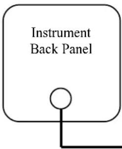
Remote Switch
Back Panel
"Wht/Violet and
Wht/Gray" Pair
To Instrument EGT or CHT Channel.
(For a twin unit, to Instrument Left or Right Channel)
"Brown" Pair
To Cyl. #1.
"Red Stripe" Pair
To Cyl. #2.
"Orange" Pair
To Cyl. #3.
"Yellow" Pair
To Cyl. #4.
"Green" Pair
To Cyl. #5 (RS-6 only).
"Blue" Pair
To Cyl. #6 (RS-6 only)
RS-4-2 and RS-6-2 Only
From the back of the RS-6-2 and RS-4-2 there are two groups of the above wires. Connect one group to the EGT Probes (or left channel for a twin installation) and connect the other group to the CHT (or right channel for a twin installation).
Remote Switch Wiring Diagram
RS-8-1 and RS-12-1
Remote Switch Back Panel
"Wht/Orange" Pair To Instrument EGT or CHT Channel.
"Solid Brown" Pair To Cyl. #1.
"Solid Red" Pair To Cyl. #2.
"Solid Orange" Pair To Cyl. #3.
"Solid Yellow" Pair To Cyl. #4.
"Solid Green" Pair To Cyl. #5.
"Solid Blue" Pair To Cyl. #6.
"Violet Stripe" Pair To Cyl #7.
"Gray Stripe" Pair To Cyl #8.
"Solid White" Pair To Cyl #9 (RS-12-1 only).
"Solid Black" Pair To Cyl #10 (RS-12-1 only).
"Brown Stripe" Pair To Cyl #11 (RS-12-1 only).
"Red Stripe" Pair To Cyl #12 (RS-12-1 only).
- Single and Multi-Channel
- EGT, CHT, Carb Temp and OAT Instruments
- Operating and Installation Instructions
- Important Installation Information 0720921
- Important Notice
- \*\*\*\*\* MUST READ \*\*\*\*\*
- Contents
- Warranty 2
- Operating Instructions: 3
- Installation Instructions: 9
- Troubleshooting Suggestions 14
- Specifications and Operating Features 16
- Instrument Wiring Diagram 17
- Remote Switch Diagram (RS-4-1, RS-4-2, RS-6-1, and RS-6-2) 18
- Remote Switch Diagram (RS-8-1 and RS-12-1) 19
- STC Information 20
- Warranty / Agreement
- OPERATING INSTRUCTIONS
- Features
- Instruments:
- Remote Switches:
- EGT's
- Leaning:
- EGT Diagnostics:
- CHT's
- CHT Operation:
- CHT Diagnostics:
- Carburetor Temperature
- Outside Air Temperature
- INSTALLATION INSTRUCTIONS
- Important Information and Initial Check Out:
- CHT Probe Installation:
- EGT Probe Installation:
- Carb Temp Probe Installation:
- OAT Probe Installation:
- Route the Extension Cables:
- Red Slip-on Connectors
- Yellow Precision Connector
- Hook-Up Connecting Wires:
- Connect and Install the Instrument and/or Remote Switch:
- System Ground Test:
- Strategy:
- Instrument Check Out:
- Probe Check Out:
- Extension Cable Check Out:
- Remote Switch Wiring Diagram
- RS-4-2 and RS-6-2 Only
Brand : Electronics International
Model : CA-1
Category : Measurement