NH-U14S DX-3647 - Composant de refroidissement pour ordinateur Noctua - Free user manual and instructions
Find the device manual for free NH-U14S DX-3647 Noctua in PDF.

| Product Type | CPU Cooler |
| Socket Compatibility | Intel LGA 3647 (Square ILM) |
| Cooler Dimensions (with fan) | 150 x 126 x 165 mm (W x D x H) |
| Cooler Dimensions (without fan) | 140 x 132 x 165 mm (W x D x H) |
| Weight (with fan) | 1030 g |
| Weight (without fan) | 780 g |
| Fan Model | Noctua NF-A15 PWM (150 mm) |
| Fan Speed (max) | 1200 RPM ±10% |
| Fan Noise (max) | 19.2 dB(A) |
| Airflow (max) | 82.5 m³/h |
| Material (base) | Nickel-plated copper |
| Material (fins) | Aluminum |
| Heat Pipes | 6 (copper, nickel-plated) |
| Max TDP | ~200 W (depending on case airflow) |
| Mounting System | Noctua SecuFirm2™ |
| Included Thermal Paste | Noctua NT-H1 |
| Warranty | 6 years |
| Maintenance | Dust removal with compressed air or soft brush; clean fan blades periodically |
| Spare Parts Available | Yes, fan clips, mounting kits, and fans separately |
Frequently Asked Questions - NH-U14S DX-3647 Noctua
User questions about NH-U14S DX-3647 Noctua
0 question about this device. Answer the ones you know or ask your own.
Ask a new question about this device
Download the instructions for your Composant de refroidissement pour ordinateur in PDF format for free! Find your manual NH-U14S DX-3647 - Noctua and take your electronic device back in hand. On this page are published all the documents necessary for the use of your device. NH-U14S DX-3647 by Noctua.
USER MANUAL NH-U14S DX-3647 Noctua
Congratulations on choosing the Noctua NH-U14S DX-3647.
Our DX line of coolers has become a default choice in high performance quiet cooling solutions for Intel Xeon CPUs and the latest DX-3647 revision supports LGA3647 (both Square and Narrow ILM) based Xeon platforms. Each Noctua product is double checked for flawless operation by our quality control team before it leaves the factory and I'm confident that you will be able to sense some of the research, attention and care we've put into making this product. Enjoy your NH-U14S DX-3647!
Yours sincerely,

This manual will guide you through the installation process of the SecuFirm2 ^™ mounting system step by step.
Prior to installing the cooler, please consult the compatibility list on our website (www.noctua.at/compatibility) and verify that the cooler is fully compatible with your motherboard. Please also make sure that your PC case offers sufficient clearance for the cooler and that there are no compatibility issues with any other components (e.g. tall RAM modules). Double check that the heatsink and fan clips do not make contact with the VGA card or other PCIe cards. Noctua cannot be held responsible for any damage or losses caused by compatibility issues.
Should you encounter any difficulties, please check the FAQs on our website (www.noctua.at/faqs) and don't hesitate to contact our support team at support@noctua.at.
Multilingual versions of this manual are available on our website: www.noctua.at/manuals
Required mounting parts:
2x NM-XFB6
brackets for square type sockets
2x NM-XFB7
brackets for narrow type sockets
Plastic processor clip square type Plastic processor clip narrow type
4x NM-SSC2 short screws NM-SMT4 mounting tool
1 Determining the socket type (square vs narrow) and selecting the appropriate brackets
Please first check if your motherboard uses square or narrow type socket(s):
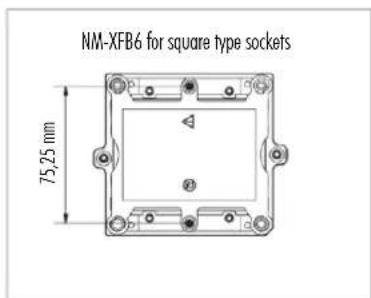
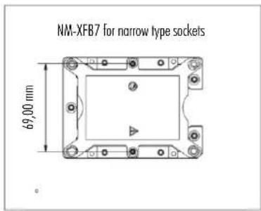
Select the NM-XFB6 brackets for square type sockets and the NM-XFB7 brackets for narrow type sockets.
This manual shows the installation procedure on square type sockets, but the procedure is identical on narrow type platforms.
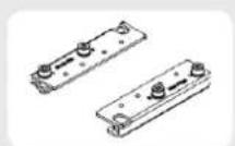
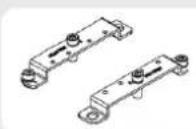
Installing the brackets2
Take the fan off the cooler. Use the included mounting tool and the short screws to install the appropriate brackets to the cooler.
natural_image
Technical line drawing of a computer cooling unit with fan and cooling fins (no text or symbols)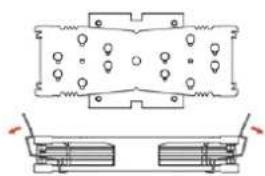
natural_image
Technical diagram of a mechanical component with two views (top and side), no visible text or symbols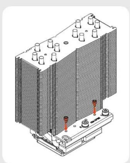
natural_image
Isometric technical diagram of a heat exchanger or cooling unit with cooling fins and red bolted components (no text or labels)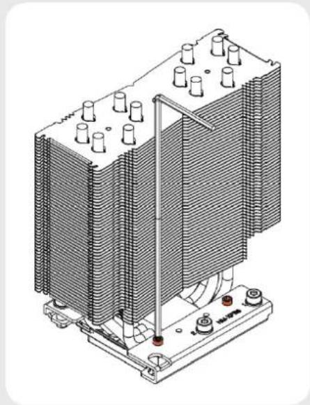
natural_image
Technical line drawing of a heat exchanger or cooling unit with cooling fins and cooling elements (no text or symbols)Caution: Gently tighten the screws until they stop, but don't use excessive force (max. torque 0.6 Nm).
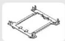
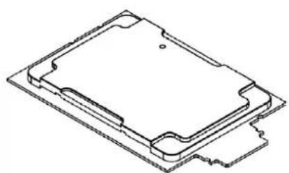
3 Putting the CPU into the processor clip and fixing it to the heatsink
The LGA3647 platform uses a plastic clip that fixes the CPU to the heatsink and ensures that it is properly inserted into the socket. There are different clips for square and narrow type sockets. Please first select the clip that matches your socket type.
natural_image
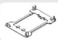
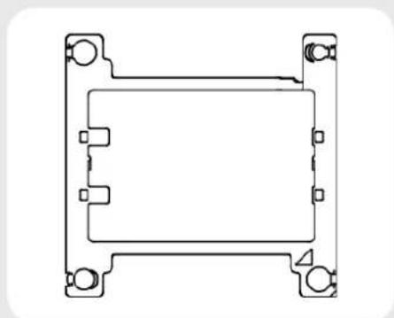
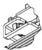
Pure technical line drawing of a rectangular mechanical component with mounting holes (no text or symbols)Put the clip upside down so that the long heatsink latches and posts for heatsink alignment are facing downwards.
natural_image
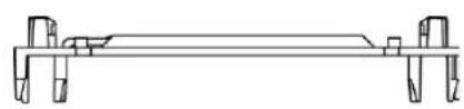
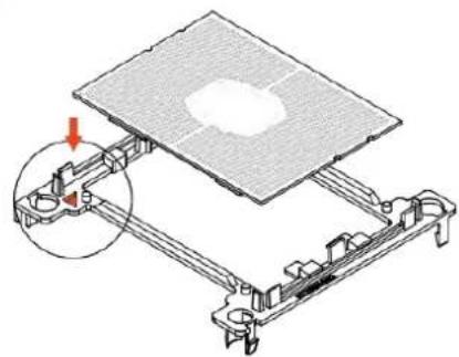
Pure mechanical assembly diagram showing a beam with supports and joints (no text or symbols)Orient the CPU so that the heatspreader is facing downwards and the golden contacts are facing upwards. Be careful not to touch the contacts. Then put the CPU into the clip, aligning the CPU's pin 1 (golden triangle indicator) with the triangle pin 1 indicator of the clip. Snap the CPU into the clip. Note that you may need to flex the clip a bit for it to latch onto the CPU. Verify that the clip is fully attached to the CPU before proceeding.
natural_image
Technical diagram of a mechanical assembly with a grid-patterned plate and bracket (no text or symbols)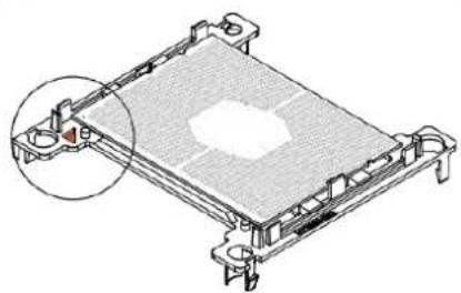
natural_image
Technical line drawing of a mechanical component with a highlighted section (no text or symbols)Caution: Some LGA3647 CPUs have a so called OmniPath fabric connector. If your CPU is of this type, you need a different processor clip. Please contact support@noctug.at if you have a CPU with OmniPath fabric connector.
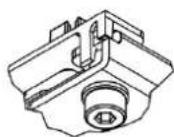
natural_image
Isometric line drawing of a mechanical component or housing (no text or symbols)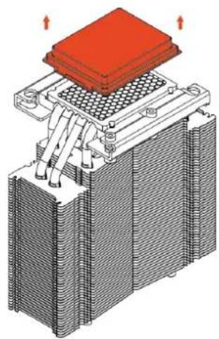
natural_image
3D diagram of a heat exchanger or cooling unit with red heating element and cooling fins (no text or symbols)Turn the heatsink upside down so that the base is facing upwards. Carefully put it down onto the tips of the heatpipes and secure it with your hand so that it cannot tilt and that the fins cannot get bent. Remove the plastic protection cover from the base of the heatsink and be careful not to damage the layer of pre-applied thermal compound.
Caution: If you are not using the heatsink for the first time and it therefore doesn't have a fresh layer of pre-applied thermal compound anymore, you need to apply a thin layer of thermal compound to the CPU yourself before clipping it to the heatsink. If there are residual traces of previous thermal paste or thermal pads on your CPU or on the heatsink, please clean them off first.
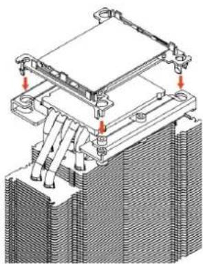
Put the processor clip and CPU assembly onto the heatsink's base so that the posts of the clip go through the holes of the heatsink's mounting brackets. Push the clip towards the heatsink's base until the latches snap to the mounting brackets.
natural_image
Technical diagram of a mechanical assembly with cooling fins and heat exchangers (no text or symbols)Verify that all the latches have snapped to the mounting brackets and that the CPU and clip are fully attached to the heatsink.
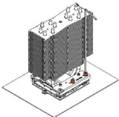
4 Installing the heatsink to the socket
Remove the plastic dust cover from the CPU socket and put the heatsink and CPU assembly onto the socket, aligning the CPU's pin 1 indicator with the pin 1 indicator of the socket.
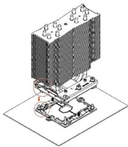
natural_image
Isometric technical diagram of a heat exchanger or cooling unit with cooling fins and cooling elements (no text or labels)Start fastening the heatsink to the socket by tightening the outer screws (number 1), starting with the screw at pin 1.
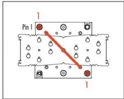
Then tighten the two center screws (number 2), starting with the screw that is on the opposite side of pin 1:
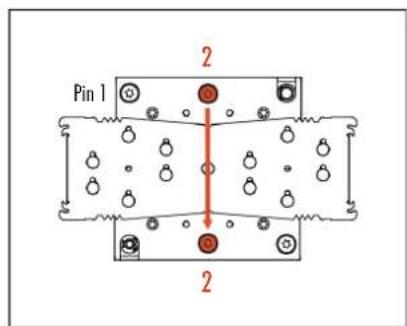
Caution: Gently tighten the screws until they stop, but don't use excessive force (max. torque 0.8 Nm).
natural_image
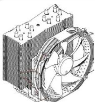
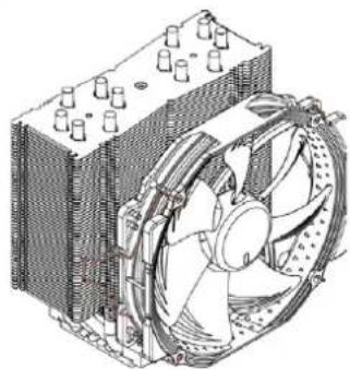
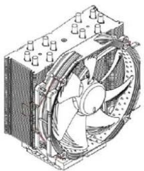
Isometric technical illustration of a heat exchanger or cooling unit with cooling fins and cooling elements (no text or symbols)Installing the fan5
Reattach the fan to the heatsink using the supplied steel clips:
natural_image
Technical illustration of a computer cooling fan assembly (no text or symbols visible)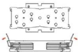
natural_image
Technical diagram of a mechanical component with two views (top and side), no visible text or symbols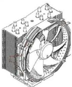
natural_image
Technical line drawing of a computer cooling fan assembly (no text or labels)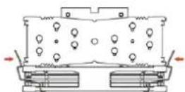
natural_image
Technical line drawing of a computer cooling fan assembly (no text or labels)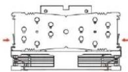
Connect the fans to the motherboard's CPU fan header(s). You can use the supplied y-cable to connect both fans to a single header.
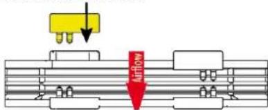
Adding a second fan
The NH-U14S DX-3647 includes an extra set of fan clips and an extra set of thicker anti-vibration pads for installing a second NF-A15 fan in push/pull mode in order to further improve cooling performance.
Please use the thicker anti-vibration pads on the rear NF-A15 fan for improved acoustics if space allows. The y-cable supplied with the retail NF-A15 fan can be used to control the speed of both fans via the same motherboard fan header.
Please note that while the NF-A15 fan included with the NH-U14S DX-3647 runs at 1500rpm, Noctua recommends using the standard 1200rpm retail version as a rear fan in push/pull mode as the combination of 1500rpm at the front and 1200rpm at the rear will provide the best balance of performance and acoustics.
- Remove standard pads on rear fan
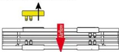
- Install thick pads on rear fan
rear fan (thick pads)
Clip position for thick pads:
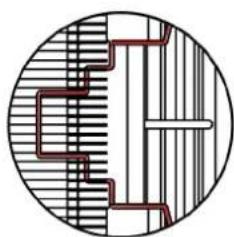
natural_image
Cross-sectional diagram of a mechanical or architectural structure with hatched and striped sections (no text or symbols)Clip position for standard pads:
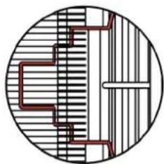
natural_image
Pure geometric diagram with concentric circles and internal lines, no text or symbols presentWhile Noctua recommends using an NF-A15 fan for best results in dual fan mode, the extra set of fan clips can also be used to install most other fans. In this case, please put the supplied self-adhesive anti-vibration strips onto the heatsink to avoid vibrations being transmitted to the cooler.
! Removing the heatsink from the socket and the CPU from the heatsink
To remove the heatsink from the socket, please first loosen the center screws (number 2) and then loosen the outer screws (number 1).
As the CPU is attached to the heatsink through the processor clip, removing the heatsink also removes the processor from the socket. To remove the processor from the heatsink, please first unclip the latches of the processor clip from the mounting brackets on one side.
Then take a flat head screwdriver, slide it in between the heatsink and the CPU from the side and twist it carefully until the thermal
compound that holds the CPU to the heatsink becomes loose.
Unclip the latches of the processor clip on the other side and take it off. Be careful not to break the latches and make sure that the CPU doesn't fall off.
Transporting your system!
As it is not possible to reliably calculate or control the forces that act upon a system during transport (e.g. in shipping), we generally recommend, for safety reasons, taking the cooler off. Noctua cannot be held responsible for any damage that may arise due to excessive stress during transport if you keep the heatsink installed.
! Warranty, Support and FAQs
Even with high-grade products and strict quality control, the possibility of defects cannot be eliminated entirely. Therefore, we aim at providing the highest possible level of reliability and convenience by offering a warranty period of 6 years and direct, fast and straightforward RMA service.
Should you encounter any problems with your NH-U14S DX-3647, please don't hesitate to contact our support team: support@noctua.at
Please also consult the FAQ section on our website: www.noctua.at/faqs
