
Omada Pro S4500-16G2F - Network switch TP-LINK - Free user manual and instructions
Find the device manual for free Omada Pro S4500-16G2F TP-LINK in PDF.


| Product Type | Managed Network Switch |
| Model | Omada Pro S4500-16G2F |
| Brand | TP-Link |
| Ports | 16 x 10/100/1000 Mbps RJ45 + 2 x Gigabit SFP Slots |
| Switching Capacity | 56 Gbps |
| MAC Address Table | 16K |
| VLAN Support | 802.1Q VLAN, up to 4K VLANs |
| Layer Features | L2+, Static Routing, DHCP Snooping, IGMP Snooping |
| Management | Web GUI, CLI (SSH/Telnet), SNMP, Omada Controller |
| Dimensions (W x D x H) | 440 x 180 x 44 mm (rack-mountable, 1U) |
| Weight | 2.5 kg (approx.) |
| Power Supply | 100-240V AC, 50/60 Hz, internal power adapter |
| Power Consumption | 20W (max) |
| Cooling | Fanless (silent operation) |
| Mounting | Rack-mountable kit included |
| Safety Standards | CE, FCC, RoHS |
| Operating Temperature | 0°C to 40°C |
| Storage Temperature | -40°C to 70°C |
| Humidity | 10% to 90% non-condensing |
| Maintenance | Clean with dry cloth; avoid liquid cleaners |
| Reparability | No user-serviceable parts; contact TP-Link support |
Frequently Asked Questions - Omada Pro S4500-16G2F TP-LINK
User questions about Omada Pro S4500-16G2F TP-LINK
0 question about this device. Answer the ones you know or ask your own.
Ask a new question about this device
Download the instructions for your Network switch in PDF format for free! Find your manual Omada Pro S4500-16G2F - TP-LINK and take your electronic device back in hand. On this page are published all the documents necessary for the use of your device. Omada Pro S4500-16G2F by TP-LINK.
USER MANUAL Omada Pro S4500-16G2F TP-LINK
Specifications are subject to change without notice. All the brands and product names are trademarks or registered trademarks of their respective holders. © 2024 TP-Link
https://www.tp-link.com
CONTENTS
Preface 1
Chapter 1 Using the CLI....8
1.1 Accessing the CLI 8
1.1.1 Logon by a console port....8 1.1.2 Logon by Telnet 11 1.1.3 Logon by SSH....13
1.2 CLI Command Modes....19 1.3 Privilege Restrictions 23 1.4 Conventions....23
1.4.1 PoE Disclaimer....23 1.4.2 Format Conventions....23 1.4.3 Special Characters 23 1.4.4 Parameter Format....24
Chapter 2 Line Commands (Only for Certain Devices)....25
2.1 line 25 2.2 media-type rj45....26
Chapter 3 User Interface....27
3.1 enable....27 3.2 service password-encryption....27 3.3 enable password....28 3.4 enable secret....29 3.5 configure 30 3.6 exit 31 3.7 end....31 3.8 clipaging 32 3.9 history 32 3.10 history clear 33
Chapter 4 User Management Commands....34
4.1 user name (password) 34 4.2 user name (secret) 35 4.3 service password-recovery 36 4.4 show user account-list....37 4.5 show user configuration 38
Chapter 5 System Configuration Commands....39
5.1 system-time manual....39
5.2 system-time ntp 39
5.3 system-time dst predefined....41
5.4 system-time dst date 42
5.5 system-time dst recurring....43
5.6 hostname....44
5.7 location 45
5.8 contact-info 45
5.9 led 46
5.10 ip address....46
5.11 ip address-alloc....47
5.12 controller cloud-based (Only for Certain Devices) 48
5.13 controller inform-url (Only for Certain Devices) 49
5.14 reset 50
5.15 Service Reset-Disable....50
5.16 Reboot....51
5.17 Reboot-Schedule 51
5.18 Copy Running-Config Startup-Config 52
5.19 Copy Startup-Config TFTP 53
5.20 Copy TFTP Startup-Config ....53
5.21 Copy Backup-Config TFTP....54
5.22 Copy Backup-Config Startup-Config 55
5.23 Copy Running-Config Backup-Config....55
5.24 Copy TFTP Backup-Config....56
5.25 Boot Application 56
5.26 Boot Config....57
5.27 Remove Backup-Image....58
5.28 Firmware Upgrade....58
5.29 Patch Load (Only for Certain Devices)....59
5.30 patch active (Only for Certain Devices)....60
5.31 patch run (Only for Certain Devices)....60
5.32 patch deactive (Only for Certain Devices)....61
5.33 patch uninstall (Only for Certain Devices) 62
5.34 patch delete (Only for Certain Devices)....62
5.35 show patch information (Only for Certain Devices)....63
5.36 mcu-firmware unit upgrade (Only for Certain Devices)....63
5.37 mcu-firmware type (Only for Certain Devices)....64 5.38 checkpoint file (Only for Certain Devices) 65 5.39 show checkpoint (Only for Certain Devices)....65 5.40 rollback running-config file (Only for Certain Devices) 66 5.41 boot autoinstall start 67 5.42 boot autoinstall persistent-mode 67 5.43 boot autoinstall auto-save....68 5.44 boot autoinstall auto-reboot 68 5.45 boot autoinstall retry-count 69 5.46 show boot autoinstall....70 5.47 show boot autoinstall downloaded-config....70 5.48 ping....71 5.49 tracert 72 5.50 show system-info....73 5.51 show image-info....73 5.52 show boot....74 5.53 show running-config 74 5.54 show startup-config....75 5.55 show system-time 75 5.56 show system-time dst....76 5.57 show system-time ntp....76 5.58 show cable-diagnostics interface....77 5.59 show cpu-utilization....77 5.60 show memory-utilization 78 5.61 show controller....78 5.62 show temperature....79 5.63 show voltage....79 5.64 clear config interface....80 5.65 power backup unit (Only for Certain Devices) 81 5.66 show power (Only for Certain Devices)....81
Chapter 6 File System Configuration Commands (Only for Certain Devices) 82
6.1 copy....82 6.2 cd 82 6.3 dir 83 6.4 pwd 83 6.5 rename 84 6.6 delete 84
6.7 ftp....85 6.8 open 86 6.9 put....86 6.10 get....87 6.11 close....87
Chapter 7 Management Port Configuration Commands (Only for Certain Devices) 89
7.1 management-port protocol 89 7.2 management-port ip....89 7.3 management-port ipv6 enable....90 7.4 management-port ipv6 address 91 7.5 show management-port....91
Chapter 8 EEE Configuration Commands ...... 93
8.1 eee....93 8.2 show interface eee 93
Chapter 9 SDM Template Commands....95
9.1 sdm prefer....95 9.2 show sdm prefer 96
Chapter 10 Time Range Commands ...... 98
10.1 time-range....98 10.2 absolute....98 10.3 periodic....99 10.4 holiday (time-range mode) 100 10.5 holiday....101 10.6 show holiday 101 10.7 show time-range 102
Chapter 11 Port Configuration Commands .... 103
11.1 interface....103 11.2 interface range 104 11.3 description....105 11.4 shutdown....105 11.5 flow-control....106 11.6 duplex....107 11.7 jumbo-size....107
11.8 speed 108 11.9 clear counters....109 11.10 show fiber-ports....109 11.11 show interface status....110 11.12 show interface counters....110 11.13 show interface configuration....111
Chapter 12 Port Isolation Commands ...... 113
12.1 port isolation....113 12.2 show port isolation interface 114
Chapter 13 Loopback Detection Commands.... 115
13.1 loopback-detection (global)....115 13.2 loopback-detection interval....115 13.3 loopback-detection recovery-time 116 13.4 loopback-detection (interface)....117 13.5 loopback-detection config process-mode....117 13.6 loopback-detection recover....118 13.7 show loopback-detection global 119 13.8 show loopback-detection interface 120
Chapter 14 Stack Commands (Only for Certain Devices).... 121
14.1 switch stack-name....121 14.2 switch stack-group....122 14.3 group-info....122 14.4 interface port 123 14.5 switch priority....123 14.6 switch renumber 124 14.7 switch provision 125 14.8 switch mac-delay....125 14.9 switch mac-delay show....126 14.10 show switch stack-ports 127 14.11 show switch....127 14.12 show switch neighbors 128
Chapter 15 DDM Commands (Only for Certain Devices).... 129
15.1 ddm state enable 129 15.2 ddm shutdown....130 15.3 ddm temperature_threshold....130
15.4 ddm voltage_threshold....131 15.5 ddm bias_current_threshold....132 15.6 ddm tx_power_threshold....133 15.7 ddm rx_power_threshold....134 15.8 show ddm configuration....135 15.9 show ddm status....136 15.10 show fiber-ports....136
Chapter 16 Etherchannel Commands ...... 138
16.1 channel-group....138 16.2 port-channel load-balance 139 16.3 lacp system-priority 140 16.4 lacp port-priority 141 16.5 show etherchannel 141 16.6 show etherchannel load-balance....142 16.7 show lacp....143 16.8 show lacp sys-id....143
Chapter 17 MAC Address Commands.... 145
17.1 mac address-table static....145 17.2 no mac address-table dynamic....146 17.3 mac address-table aging-time 146 17.4 mac address-table filtering....147 17.5 mac address-table notification 148 17.6 mac address-table max-mac-count....149 17.7 mac address-table notification (interface)....150 17.8 mac address-table security 151 17.9 mac address-table vlan-security 152 17.10 show mac address-table 153 17.11 clear mac address-table 154 17.12 show mac address-table aging-time....154 17.13 show mac address-table max-mac-count 155 17.14 show mac address-table interface....156 17.15 show mac address-table count....156 17.16 show mac address-table address.... 157 17.17 show mac address-table vlan....158 17.18 show mac address-table notification....158 17.19 show mac address-table security....159
Chapter 18 IEEE 802.1Q VLAN Commands .... 160
18.1 vlan....160 18.2 name....161 18.3 vlan_trunk (globally)....161 18.4 vlan_trunk (interface)....162 18.5 switchport general allowed vlan....163 18.6 switchport pvid....163 18.7 switchport check ingress....164 18.8 switchport acceptable frame....165 18.9 show vlan summary 166 18.10 show vlan brief....166 18.11 show vlan....167 18.12 show interface switchport....167
Chapter 19 MAC-based VLAN Commands.... 169
19.1 mac-vlan mac-address....169 19.2 mac-vlan....170 19.3 show mac-vlan....170 19.4 show mac-vlan interface 171
Chapter 20 Protocol-based VLAN Commands ...... 172
20.1 protocol-vlan template 172 20.2 protocol-vlan vlan....173 20.3 protocol-vlan group....174 20.4 show protocol-vlan template....175 20.5 show protocol-vlan vlan....176
Chapter 21 Private VLAN Commands (Only for Certain Devices) ..... 177
21.1 private-vlan primary....177 21.2 private-vlan community....177 21.3 private-vlan isolated....178 21.4 private-vlan association....179 21.5 switchport private-vlan....179 21.6 switchport private-vlan host-association....180 21.7 switchport private-vlan mapping 181 21.8 show vlan private-vlan 182 21.9 show vlan private-vlan interface 182
Chapter 22 VLAN-VPN Commands (Only for Certain Devices)....184
22.1 dot1q-tunnel....184 22.2 switchport dot1q-tunnel tpid....185 22.3 dot1q-tunnel mapping....185 22.4 switchport dot1q-tunnel mode 186 22.5 switchport dot1q-tunnel missdrop (only for certain devices)....187 22.6 switchport dot1q-tunnel use_inner_priority 188 22.7 switchport dot1q-tunnel mapping....188 22.8 switchport dot1q-tunnel replace 189 22.9 switchport dot1q-tunnel replace-out....190 22.10 show dot1q-tunnel....191 22.11 show dot1q-tunnel mapping....192 22.12 show dot1q-tunnel interface 192
Chapter 23 ERPS Commands....194
23.1 erps ring....194 23.2 control-vlan....194 23.3 description....195 23.4 guard-timer 196 23.5 wtr-timer....196 23.6 holdoff-timer....197 23.7 protected-instance....198 23.8 raps-mel....198 23.9 revertive....199 23.10 sub-ring....200 23.11 tc-notify erps 200 23.12 tc-protection interval 201 23.13 tc-protection threshold 201 23.14 version 202 23.15 virtual-channel....203 23.16 erps ring rpl 203 23.17 erps ring protect-switch....204 23.18 show erps ring 205
Chapter 24 GVRP Commands....206
24.1 gvrp....206 24.2 gvrp (interface) 206 24.3 gvrp registration....207
24.4 gvrp timer 208 24.5 show gvrp interface....209 24.6 show gvrp global 210
Chapter 25 IGMP Snooping Commands....211
25.1 ip igmp snooping (global)....211 25.2 ip igmp snooping version 211 25.3 ip igmp snooping drop-unknown 212 25.4 ip igmp snooping header-validation....213 25.5 ip igmp snooping vlan-config 213 25.6 ip igmp snooping vlan-config (immediate-leave) 215 25.7 ip igmp snooping vlan-config (report-suppression) 216 25.8 ip igmp snooping vlan-config (router-ports-forbidden)....217 25.9 ip igmp snooping vlan-config (rport interface)....218 25.10 ip igmp snooping vlan-config (static) 218 25.11 ip igmp snooping vlan-config (querier) 219 25.12 ip igmp snooping (interface) 221 25.13 ip igmp snooping max-groups....221 25.14 ip igmp snooping immediate-leave....223 25.15 ip igmp snooping authentication....223 25.16 ip igmp snooping accounting 224 25.17 ip igmp profile 225 25.18 deny....225 25.19 permit....226 25.20 range 226 25.21 ip igmp filter 227 25.22 clear ip igmp snooping statistics 228 25.23 show ip igmp snooping....228 25.24 show ip igmp snooping interface 229 25.25 show ip igmp snooping vlan 230 25.26 show ip igmp snooping groups 230 25.27 show ip igmp profile....231
Chapter 26 Layer 3 IGMP Commands (Only for Certain Devices).... 233
26.1 ip igmp (global)....233 26.2 ip igmp (on specific ports) 233 26.3 ip igmp header-validation....234 26.4 ip igmp version 234
26.5 ip igmp last-member-query-count 235 26.6 ip igmp last-member-query-interval....236 26.7 ip igmp query-interval 237 26.8 ip igmp query-max-response-time 237 26.9 ip igmp robustness....238 26.10 ip igmp startup-query-interval....239 26.11 ip igmp last-member-query-count 239 26.12 show ip igmp....240 26.13 show ip igmp groups 241 26.14 show ip igmp groups interface 241 26.15 show ip igmp groups interface vlan....242 26.16 show ip igmp groups interface vlan....243 26.17 show ip igmp interface vlan....243
Chapter 27 PIM Commands (Only for Certain Devices).... 245
27.1 ip multicast-routing 245 27.2 ip pim (globally) 245 27.3 ip pim (on specific ports)....246 27.4 ip pim bsr-candidate interface 247 27.5 ip pim rp-candidate interface....247 27.6 ip pim rp-address....248 27.7 ip pim bsr-border 249 27.8 ip pim ssm 250 27.9 ip pim dr-priority....250 27.10 ip pim hello-interval 251 27.11 ip pim join-prune-interval....252 27.12 show ip multicast 252 27.13 show ip mroute 253 27.14 show ip pim interface 253 27.15 show ip pim neighbor 254 27.16 show ip pim statistic 255 27.17 show ip pim bsr-router 255 27.18 show ip pim bsr-router 256 27.19 show ip pim rp-hash 257
Chapter 28 Static Multicast Routing Commands (Only for Certain Devices) .. 258
28.1 ip mroute 258 28.2 show ip mroute static....259
Chapter 29 MLD Snooping Commands....260
29.1 ipv6 mld snooping (global)....260
29.2 ipv6 mld snooping drop-unknown 260
29.3 ipv6 mld snooping vlan-config 261
29.4 ipv6 mld snooping vlan-config (immediate-leave) 262
29.5 ipv6 mld snooping vlan-config (report-suppression) 263
29.6 ipv6 mld snooping vlan-config (router-ports-forbidden)....264
29.7 ipv6 mld snooping vlan-config (rport interface) 265
29.8 ipv6 mld snooping vlan-config (static) 265
29.9 ipv6 mld snooping vlan-config (querier) 266
29.10 ipv6 mld snooping (interface) 268
29.11 ipv6 mld snooping max-groups....268
29.12 ipv6 mld snooping immediate-leave 270
29.13 ipv6 mld profile....270
29.14 deny....271
29.15 permit....271
29.16 range 272
29.17 ipv6 mld filter 273
29.18 clear ipv6 mld snooping statistics 273
29.19 show ipv6 mld snooping....274
29.20 show ipv6 mld snooping interface 274
29.21 show ipv6 mld snooping vlan....275
29.22 show ipv6 mld snooping groups 276
29.23 show ipv6 mld profile 276
Chapter 30 MVR Commands....278
30.1 mvr (global) 278
30.2 mvr group 278
30.3 mvr mode 279
30.4 mvr querytime 280
30.5 mvr vlan 281
30.6 mvr (interface) 281
30.7 mvr type 282
30.8 mvr immediate 283
30.9 mvr vlan (group) 283
30.10 mvr vlan (rule) 284
30.11 mvr mode dynamic auto-enable 285
30.12 show mvr 285
30.13 show mvr interface 286 30.14 show mvr members 286
Chapter 31 MSTP Commands 288
31.1 debug spanning-tree 288 31.2 spanning-tree (global) 289 31.3 spanning-tree (interface) 289 31.4 spanning-tree common-config 290 31.5 spanning-tree mode 291 31.6 spanning-tree mst configuration 292 31.7 instance 293 31.8 name 293 31.9 revision 294 31.10 spanning-tree mst instance 295 31.11 spanning-tree mst 295 31.12 spanning-tree priority 296 31.13 spanning-tree timer 297 31.14 spanning-tree hold-count 298 31.15 spanning-tree max-hops 298 31.16 spanning-tree bpdufilter 299 31.17 spanning-tree bpduflood 300 31.18 spanning-tree bpduguard 300 31.19 spanning-tree guard loop 301 31.20 spanning-tree guard root 302 31.21 spanning-tree guard tc 302 31.22 spanning-tree mcheck 303 31.23 show spanning-tree active 303 31.24 show spanning-tree bridge 304 31.25 show spanning-tree interface 304 31.26 show spanning-tree interface-security 305 31.27 show spanning-tree mst 306
Chapter 32 Debug Commands 309
32.1 debug tppacket packet-print (only for certain devices)....309 32.2 debug spanning-tree....309
Chapter 33 LLDP Commands....311
33.1 lldp 311 33.2 lldp forward_message....311
33.3 lldp hold-multiplier 312 33.4 lldp timer 313 33.5 lldp receive....314 33.6 lldp transmit 314 33.7 lldp snmp-trap 315 33.8 lldp tlv-select 316 33.9 lldp management-address 316 33.10 lldp med-fast-count....317 33.11 lldp med-status 318 33.12 lldp med-tlv-select....318 33.13 lldp med-location 319 33.14 show lldp....320 33.15 show lldp interface....320 33.16 show lldp local-information interface....321 33.17 show lldp neighbor-information interface 322 33.18 show lldp traffic interface 322
Chapter 34 L2PT Commands (Only for Certain Devices)....324
34.1 l2protocol-tunnel....324 34.2 l2protocol-tunnel type 325 34.3 show l2protocol-tunnel global....326 34.4 show l2protocol-tunnel interface 327 34.5 l2protocol-tunnel dst-mac 327 34.6 show l2protocol-tunnel dst-mac 328
Chapter 35 PPPoE ID-Insertion Commands (Only for Certain Devices)....329
35.1 pppoe id-insertion (global)....329 35.2 pppoe circuit-id (interface)....330 35.3 pppoe circuit-id type....330 35.4 pppoe remote-id....331 35.5 show pppoe id-insertion global 332 35.6 show pppoe id-insertion interface....333
Chapter 36 Static Routes Commands ...... 334
36.1 ip routing....334 36.2 interface vlan 334 36.3 interface loopback....335 36.4 switchport 335 36.5 interface range port-channel....336
36.6 description....337 36.7 shutdown....337 36.8 interface port-channel 338 36.9 ip route....339 36.10 ipv6 routing 340 36.11 ipv6 route 340 36.12 show interface vlan....341 36.13 show ip interface....341 36.14 show ip interface brief....342 36.15 show ip route 343 36.16 show ip route specify 343 36.17 show ip route summary....344 36.18 show ipv6 interface 345 36.19 show ipv6 route 345 36.20 show ipv6 route summary 346
Chapter 37 RIP Configuration Commands (Only for Certain Devices) ...... 347
37.1 router rip 347 37.2 network....347 37.3 version 348 37.4 timer basic 349 37.5 distance 350 37.6 auto-summary 350 37.7 default-metric 351 37.8 redistribute....351 37.9 allow-ecmp....352 37.10 default-information originate 353 37.11 neighbor....353 37.12 passive-interface 354 37.13 ip rip authentication mode....354 37.14 ip rip authentication string....355 37.15 ip rip authentication key-chain 356 37.16 ip rip receive version 357 37.17 ip rip send version....357 37.18 ip rip split-horizon 358 37.19 ip rip v2-broadcast 359 37.20 show ip rip 359 37.21 show ip rip status 360
37.22 clear ip rip 360
Chapter 38 RIPng Configuration Commands (Only for Certain Devices) ...... 361
38.1 router ripng 361 38.2 ipv6 rip enable 361 38.3 timer basic 362 38.4 default-metric 363 38.5 redistribute 363 38.6 allow-ecmp 364 38.7 default-information originate 365 38.8 passive-interface 365 38.9 ip rip split-horizon 366 38.10 show ipv6 rip 367 38.11 show ipv6 rip status 367 38.12 clear ipv6 rip 367
Chapter 39 OSPF Configuration Commands (Only for Certain Devices) 369
39.1 router ospf 369 39.2 router-id 370 39.3 network 370 39.4 maximum-paths 371 39.5 redistribute 372 39.6 default-metric 373 39.7 default-metric 373 39.8 auto-cost 374 39.9 distance 375 39.10 timers throttle spf 376 39.11 compatible rfc 1583 376 39.12 area stub 377 39.13 area nssa 378 39.14 area default-cost 379 39.15 area range 379 39.16 area authentication 381 39.17 area virtual-link 381 39.18 area virtual-link authentication 382 39.19 area virtual-link authentication-key 383 39.20 area virtual-link message-digest-key 384 39.21 capability opaque 385
39.22 graceful-restart 386
39.23 graceful-restart grace-period 387
39.24 graceful-restart helper 387
39.25 graceful-restart helper planned-only 388
39.26 graceful-restart helper strict-lsa-checking 389
39.27 ip ospf cost 389
39.28 ip ospf retransmit-interval 390
39.29 ip ospf transmit-delay 391
39.30 ip ospf priority 391
39.31 ip ospf hello-interval 392
39.32 ip ospf dead-interval 393
39.33 ip ospf authentication 393
39.34 ip ospf authentication-key 394
39.35 ip ospf message-digest-key 395
39.36 ip ospf network....395
39.37 ip ospf mtu-ignore 396
39.38 ip ospf passive....397
39.39 clear ip ospf....397
39.40 show ip ospf....398
39.41 show ip ospf database 398
39.42 show ip ospf interface....399
39.43 show ip ospf neighbor....399
39.44 show ip ospf border-routers....400
39.45 show ip ospf route 401
39.46 show ip ospf [process-id] graceful-restart helper 401
Chapter 40 OSPFv3 Configuration Commands (Only for Certain Devices) ..... 402
40.1 ipv6 router ospf....402
40.2 router-id....402
40.3 maximum-paths 403
40.4 redistribute....404
40.5 default-information originate 404
40.6 auto-cost....405
40.7 distance 406
40.8 distance ospf 407
40.9 timers throttle spf 407
40.10 timers Isa arrival 408
40.11 area stub....409
40.12 area nssa 410 40.13 area range 410 40.14 ipv6 ospf area 411 40.15 ipv6 ospf cost 412 40.16 ipv6 ospf retransmit-interval....413 40.17 ipv6 ospf transmit-delay 413 40.18 ipv6 ospf priority 414 40.19 ipv6 ospf hello-interval....415 40.20 ipv6 ospf dead-interval 415 40.21 ipv6 ospf network 416 40.22 ipv6 ospf mtu-ignore 417 40.23 ipv6 ospf passive 417 40.24 clear ipv6 ospf 418 40.25 show ipv6 ospf....418 40.26 show ipv6 ospf database....419 40.27 show ipv6 ospf interface 419 40.28 show ipv6 ospf neighbor 420 40.29 show ipv6 ospf border-routers 420 40.30 show ipv6 ospf rib 421
Chapter 41 BFD Configuration Commands (Only for Certain Devices).... 422
41.1 bfd-template 422 41.2 detect-multiplier....423 41.3 receive-interval 423 41.4 transmit-interval....424 41.5 transmit-interval....425 41.6 passive-mode....425 41.7 ip ospf bfd 426 41.8 ip ospf bfd template 427 41.9 ipv6 ospf bfd 428 41.10 ipv6 ospf bfd 428 41.11 isis bfd 429 41.12 show bfd counters....430 41.13 show bfd neighbors....431
Chapter 42 BGP Configuration Commands (Only for Certain Devices) ...... 432
42.1 router bgp....432 42.2 aggregate-address....433
42.3 distance bgp 434 42.4 maximum-paths 434 42.5 network 435 42.6 redistribute 436 42.7 timers bgp 436 42.8 bgp always-compare-med 437 42.9 bgp bestpath as-path confed 438 42.10 bgp bestpath as-path ignore 439 42.11 bgp bestpath as-path multipath-relax 439 42.12 bgp bestpath compare-routerid 440 42.13 bgp bestpath med confed 441 42.14 bgp bestpath med missing-as-worst 441 42.15 bgp client-to-client reflection 442 42.16 bgp cluster-id 443 42.17 bgp cluster-id 443 42.18 bgp confederation peers 444 42.19 bgp dampening 445 42.20 bgp default ipv4-unicast 445 42.21 bgp default local-preference 446 42.22 bgp deterministic-med 447 42.23 bgp enforce-first-as 447 42.24 bgp fast-external-failover 448 42.25 bgp network import-check 449 42.26 bgp router-id 449 42.27 neighbor activate 450 42.28 neighbor advertisement-interval 451 42.29 neighbor allowas-in 452 42.30 neighbor attribute-unchanged 452 42.31 neighbor capability dynamic 453 42.32 neighbor default-originate 454 42.33 neighbor description 454 42.34 neighbor disable-connected-check 455 42.35 neighbor distribute-list 456 42.36 neighbor dont-capability-negotiate 457 42.37 neighbor ebgp-multihop 457 42.38 neighbor local-as 458 42.39 neighbor maximum-prefix 459 42.40 neighbor next-hop-self 460
42.41 neighbor override-capability 460 42.42 neighbor passive 461 42.43 neighbor password 462 42.44 neighbor peer-group 462 42.45 neighbor port 463 42.46 neighbor remote-as 464 42.47 neighbor remove-private-AS 464 42.48 neighbor route-reflector-client 465 42.49 neighbor shutdown 466 42.50 neighbor soft-reconfiguration inbound 466 42.51 neighbor strict-capability-match 467 42.52 neighbor timers 468 42.53 neighbor timers connect 469 42.54 neighbor ttl-security hops 469 42.55 neighbor update-source 470 42.56 neighbor weight 471 42.57 show ip bgp 471 42.58 show ip bgp attribute-info 472 42.59 show ip bgp cidr-only 472 42.60 show ip bgp dampening flap-statistics 473 42.61 show ip bgp dampening dampened-paths 473 42.62 show ip bgp dampening parameters 474 42.63 show ip bgp neighbors 475 42.64 show ip bgp neighbors advertised-routes 475 42.65 show ip bgp neighbors advertised-routes 476 42.66 show ip bgp neighbors flap-statistics 476 42.67 show ip bgp neighbors prefix-counts 477 42.68 show ip bgp neighbors received-routes 477 42.69 show ip bgp neighbors routes 478 42.70 show ip bgp nexthop 479 42.71 show ip bgp paths 479 42.72 show ip bgp specify 480 42.73 show ip bgp summary 480 42.74 clear ip bgp 481 42.75 clear ip bgp all 481 42.76 clear ip bgp dampening 482
Chapter 43 IS-IS Configuration Commands (Only for Certain Devices) ...... 483
43.1 router isis 483
43.2 area-password 483
43.3 domain-password 484
43.4 hostname 485
43.5 is-type 486
43.6 log-adjacency-changes 486
43.7 lsp-gen-interval 487
43.8 lsp-mtu 488
43.9 lsp-refresh-interval 488
43.10 max-lsp-lifetime 489
43.11 metric-style 490
43.12 net 490
43.13 purge-originator....491
43.14 set-attached-bit 491
43.15 set-overload-bit 492
43.16 spf prefix-priority 493
43.17 clear isis neighbor....494
43.18 redistribute....494
43.19 distance 495
43.20 ip router isis....496
43.21 isis bfd....496
43.22 isis circuit-type....497
43.23 isis csnp-interval 498
43.24 isis hello-interval 498
43.25 isis hello-multiplier 499
43.26 isis metric 500
43.27 isis network point-to-point....500
43.28 isis passive....501
43.29 isis password-key 502
43.30 isis priority....502
43.31 isis three-way-handshake 503
43.32 show isis database....504
43.33 show isis hostname 504
43.34 show isis neighbor 505
43.35 show isis route....505
43.36 show isis summary....506
43.37 show isis interface 507
Chapter 44 URPF Configuration Commands (Only for Certain Devices) ..... 508
44.1 urpf 508 44.2 urpf mode 508
Chapter 45 Tunnel Configuration Commands (Only for Certain Devices)...... 510
45.1 interface tunnel 510 45.2 tunnel mode 511 45.3 interface tunnel 511 45.4 tunnel destination....512 45.5 tunnel ttl 513 45.6 tunnel ip address....513 45.7 shutdown....514 45.8 ip route tunnel....515 45.9 ipv6 route tunnel 515 45.10 show interface tunnel....516
Chapter 46 IPv6 Address Configuration Commands....518
46.1 ipv6 enable....518 46.2 ipv6 address autoconfig....518 46.3 ipv6 address link-local 519 46.4 ipv6 address dhcp 520 46.5 ipv6 address ra....520 46.6 ipv6 address eui-64....521 46.7 ipv6 address 522 46.8 show ipv6 interface 523
Chapter 47 ARP Commands....524
47.1 arp....524 47.2 clear arp-cache 525 47.3 arp dynamicrenew 525 47.4 arp timeout....526 47.5 gratuitous-arp intf-status-up enable....526 47.6 gratuitous-arp dup-ip-detected enable....527 47.7 gratuitous-arp learning enable 528 47.8 gratuitous-arp send-interval....528 47.9 ip proxy-arp....529 47.10 ip local-proxy-arp....530
47.11 show arp 530 47.12 show ip arp (interface)....531 47.13 show ip arp summary 532 47.14 show gratuitous-arp 532 47.15 show ip proxy-arp 533
Chapter 48 VRRP Commands (Only for Certain Devices)....534
48.1 ip vrrp vrid....534 48.2 ipv6 vrrp vrid....535 48.3 ip vrrp vrid authentication-mode....535 48.4 ip vrrp vrid description....536 48.5 ip vrrp vrid preempt-mode 537 48.6 ip vrrp vrid priority....538 48.7 ip vrrp vrid timer-advertise....539 48.8 ip vrrp vrid track 539 48.9 ip vrrp vrid version 540 48.10 ip vrrp vrid virtual-ip....541 48.11 ip vrrp vrid virtual-ip secondary....542 48.12 ipv6 vrrp vrid address link-local 543 48.13 ipv6 vrrp vrid address....544 48.14 show ip vrrp....544 48.15 show ip vrrp statistics 545 48.16 clear ip vrrp statistics....546
Chapter 49 DHCP Server Commands....547
49.1 service dhcp server 547 49.2 ip dhcp server extend-option capwap-ac-ip 547 49.3 ip dhcp server extend-option vendor-class-id....548 49.4 ip dhcp server excluded-address 549 49.5 ip dhcp server pool....550 49.6 ip dhcp server ping timeout 550 49.7 ip dhcp server ping packets....551 49.8 network....552 49.9 lease 552 49.10 address hardware-address....553 49.11 address client-identifier....554 49.12 default-gateway 554 49.13 dns-server 555
49.14 netbios-name-server 556 49.15 netbios-node-type....556 49.16 next-server....557 49.17 domain-name....558 49.18 bootfile....558 49.19 option 559 49.20 show ip dhcp server status 560 49.21 show ip dhcp server statistics....560 49.22 show ip dhcp server extend-option....561 49.23 show ip dhcp server pool 561 49.24 show ip dhcp server excluded-address....562 49.25 show ip dhcp server manual-binding 562 49.26 show ip dhcp server binding 563 49.27 clear ip dhcp server statistics....563 49.28 clear ip dhcp server binding....564
Chapter 50 DHCP Relay Commands....565
50.1 service dhcp relay....565 50.2 ip dhcp relay hops....565 50.3 ip dhcp relay time....566 50.4 ip helper-address....567 50.5 ip dhcp relay information option 567 50.6 ip dhcp relay information strategy....568 50.7 ip dhcp relay information format....569 50.8 ip dhcp relay information circuit-id....570 50.9 ip dhcp relay information remote-id....571 50.10 ip dhcp relay default-interface 571 50.11 ip dhcp relay vlan .... 572 50.12 show ip dhcp relay 573
Chapter 51 DHCPV6 Relay Commands....574
51.1 ipv6 dhcp relay 574 51.2 ipv6 dhcp relay vlan 1 helper-address 574 51.3 ipv6 dhcp relay information option 18 575 51.1 Switch(config-if)# ipv6 dhcp relay information option18 576 51.2 576 51.3 576 51.4 ipv6 dhcp relay information option37 576
51.5 ipv6 dhcp relay information remote-id 576 51.6 show ipv6 dhcp relay 577 51.7 show ipv6 dhcp relay counters 578
Chapter 52 DHCP L2 Relay Commands 579
52.1 ip dhcp l2relay 579 52.2 ip dhcp l2relay vlan 579 52.3 ip dhcp l2relay information option 580 52.4 ip dhcp l2relay information strategy 581 52.5 ip dhcp l2relay information format 582 52.6 ip dhcp l2relay information circuit-id 583 52.7 ip dhcp l2relay information remote-id 583 52.8 show ip dhcp l2relay 584 52.9 show ip dhcp l2relay interface 585
Chapter 53 DHCPV6 L2 Relay Commands 586
53.1 ipv6 dhcp l2relay 586 53.2 ipv6 dhcp l2relay vlan 586 53.3 ipv6 dhcp l2relay information option18 587 53.4 ipv6 dhcp l2relay information option37 588 53.5 ipv6 dhcp l2relay information remote-id 588 53.6 show ipv6 dhcp l2relay interface 589
Chapter 54 QoS Commands 590
54.1 qos trust mode 590 54.2 qos port-priority 591 54.3 qos cos-map 591 54.4 qos dot1p-remap 592 54.5 qos dscp-map 593 54.6 qos dscp-remap 594 54.7 qos queue bandwidth 595 54.8 qos queue mode 596 54.9 qos localPri 597 54.10 qos cosPri 598 54.11 qos dscpPri 599 54.12 qos wired-profile 599 54.13 qos wred-bind 600 54.14 show qos wred-profile 601 54.15 show qos wred-bind interface 601
54.16 show qos cos-map 602 54.17 show qos dot1p-remap interface 602 54.18 show qos dot1p-remap 603 54.19 show qos dscp-map interface 603 54.20 show qos dscp-map 604 54.21 show qos dscp-remap interface 604 54.22 show qos dscp-remap 605 54.23 show qos port-priority interface 606 54.24 show qos trust interface 606 54.25 show qos queue interface 607
Chapter 55 Bandwidth Control Commands 608
55.1 storm-control rate-mode 608 55.2 storm-control 609 55.3 storm-control exceed 610 55.4 storm-control recover 611 55.5 bandwidth 611 55.6 show storm-control 612 55.7 show bandwidth 613
Chapter 56 OUI-Based VLAN Commands (Only for Certain Devices) 614
56.1 voice vlan 614 56.2 voice-vlan(interface) 615 56.3 show voice-vlan 616
Chapter 57 Voice VLAN Commands 617
57.1 voice vlan 617 57.2 voice vlan (interface) 617 57.3 voice vlan priority 618 57.4 voice vlan oui 619 57.5 show voice vlan 619 57.6 show voice vlan oui-table 620 57.7 show voice vlan interface 620
Chapter 58 Auto VoIP Commands....622
58.1 auto-voip 622 58.2 auto-voip (interface) 622 58.3 auto-voip dot1p....623 58.4 auto-voip untagged 624
58.5 auto-voip none 624 58.6 no auto-voip (interface)....625 58.7 auto-voip dscp 625 58.8 auto-voip data priority....626 58.9 show auto-voip....626
Chapter 59 Access Control Commands 628
59.1 user access-control ip-based enable 628 59.2 user access-control ip-based 628 59.3 user access-control mac-based enable....629 59.4 user access-control mac-based....630 59.5 user access-control port-based enable 631 59.6 user access-control port-based 631 59.7 user access-control ipv6-based enable 632 59.8 user access-control ipv6-based....633
Chapter 60 HTTP and HTTPS Commands 634
60.1 ip http server....634 60.2 ip http port....635 60.3 ip http max-users....635 60.4 ip http session timeout 636 60.5 ip http secure-server....637 60.6 ip http secure-port....637 60.7 ip http secure-protocol....638 60.8 ip http secure-ciphersuite 639 60.9 ip http secure-max-users 640 60.10 ip http secure-session timeout 641 60.11 ip http secure-server download certificate....641 60.12 ip http secure-server download key....642 60.13 show ip http configuration....643 60.14 show ip http secure-server 644
Chapter 61 SSH Commands....645
61.1 ip ssh server....645 61.2 ip ssh port....645 61.3 ip ssh algorithm....646 61.4 ip ssh algorithm compatibility....647 61.5 ip ssh timeout 647 61.6 ip ssh max-client 648
61.7 ip ssh download....649 61.8 remove public-key....649 61.9 show ip ssh....650
Chapter 62 Telnet Commands....651
62.1 telnet 651 62.2 telnet enable 651 62.3 telnet port....652 62.4 show telnet-status....652
Chapter 63 Serial Port Commands....654
63.1 serial_port baud-rate....654
Chapter 64 AAA Commands 655
64.1 tacacs-server host 655 64.2 show tacacs-server 656 64.3 radius-server host 657 64.4 radius-server radsec-profile 658 64.5 download ca-certificate 659 64.6 download client-certificate 660 64.7 download client-key 660 64.8 radius-server host 661 64.9 show radius-server 662 64.10 radius-server load-balance algorithm 663 64.11 radius-server load-balance least-outstanding 663 64.12 radius-server dead-count 664 64.13 radius-server dead-cycle 665 64.14 radius-server dead-interval 665 64.15 radius-server dead-time 666 64.16 radius-server max-unresponsive-interval 667 64.17 radius-server testuser 667 64.18 radius-server detect-server 668 64.19 aaa group 669 64.20 server 670 64.21 show aaa group 670 64.22 aaa authentication login 671 64.23 aaa authentication enable 672 64.24 aaa authentication dot1x default 673 64.25 aaa accounting dot1x default 674
64.26 show aaa authentication 674
64.27 show aaa accounting 675
64.28 line telnet 675
64.29 login authentication (telnet) 676
64.30 line ssh 677
64.31 login authentication (ssh) 677
64.32 line console 678
64.33 login authentication (console) 679
64.34 enable authentication (telnet) 679
64.35 enable authentication (ssh) 680
64.36 enable authentication (console) 681
64.37 ip http login authentication 682
64.38 ip http enable authentication 683
64.39 show aaa global 683
64.40 enable admin password....684
64.41 enable admin secret....685
64.42 enable-admin....686
Chapter 65 IEEE 802.1x Commands....687
65.1 dot1x system-auth-control....687
65.2 dot1x handshake....688
65.3 dot1x auth-protocol 688
65.4 dot1x vlan-assignment 689
65.5 dot1x accounting....690
65.6 dot1x mab 691
65.7 dot1x guest-vlan 691
65.8 dot1x timeout quiet-period....692
65.9 dot1x timeout supp-timeout....693
65.10 dot1x max-req 694
65.11 dot1x 694
65.12 dot1x port-control 695
65.13 dot1x port-method 696
65.14 dot1x auth-init 697
65.15 dot1x auth-reauth 697
65.16 show dot1x global 698
65.17 show dot1x interface 699
65.18 show dot1x auth-state interface 699
Chapter 66 Port Security Commands (Only for Certain Devices) 701
66.1 mac address-table max-mac count 701 66.2 mac address-table sticky mac 702 66.3 mac address-table sticky save-time 703
Chapter 67 MACsec Commands (Only for Certain Devices) 704
67.1 macsec mka-policy 704 67.2 macsec apply-policy 705 67.3 macsec cipher_suite 705 67.4 macsec confidentiality-offset 706 67.5 macsec desire 707 67.6 macsec mka 707 67.7 macsec mka priority 708 67.8 macsec mka psk 709 67.9 macsec mka timer 709 67.10 macsec replay-protection 710 67.11 macsec validation-mode 711
Chapter 68 Port Mirroring Commands 712
68.1 monitor session destination interface 712 68.2 monitor session source 713 68.3 monitor session 1 destination remote vlan 714 68.4 monitor session 1 source remote vlan 715 68.5 show monitor session 716
Chapter 69 ACL Commands 717
69.1 access-list create 717 69.2 access-list packet-content profile 717 69.3 access-list resequence 718 69.4 access-list mac 719 69.5 access-list ip 720 69.6 access-list combined 722 69.7 access-list ipv6 724 69.8 access-list packet-content config 726 69.9 access-list action 727 69.10 redirect 728 69.11 s-condition 729 69.12 s-mirror 730
69.13 qos-remark....730 69.14 access bind....731 69.15 show access-list 732 69.16 show access-list bind....732 69.17 show access-list status 733 69.18 show access-list counter 733 69.19 clear access-list 734
Chapter 70 IPv4 IMPB Commands....735
70.1 ip source binding....735 70.2 ip dhcp snooping 736 70.3 ip dhcp snooping vlan 737 70.4 ip dhcp snooping max-entries....737 70.5 ip dhcp snooping trust....738 70.6 show ip source binding....739 70.7 show ip dhcp snooping....739 70.8 show ip dhcp snooping interface....740
Chapter 71 IPv6 IMPB Commands....741
71.1 ipv6 source binding 741 71.2 ipv6 dhcp snooping....742 71.3 ipv6 dhcp snooping vlan....743 71.4 ipv6 dhcp snooping max-entries 743 71.5 ipv6 nd snooping....744 71.6 ipv6 nd snooping vlan 745 71.7 ipv6 nd snooping max-entries 745 71.8 show ipv6 source binding....746 71.9 show ipv6 dhcp snooping....747 71.10 show ipv6 dhcp snooping interface 747 71.11 show ipv6 nd snooping....748 71.12 show ipv6 nd snooping interface 748
Chapter 72 IP Verify Source Commands....750
72.1 ip verify source....750 72.2 ip verify source logging....751 72.3 show ip verify source 751 72.4 show ip verify source interface 752
Chapter 73 IPv6 Verify Source Commands 753
73.1 ipv6 verify source....753 73.2 show ipv6 verify source 754 73.3 show ipv6 verify source interface....754
Chapter 74 DHCPv4 Filter Commands....756
74.1 ip dhcp filter 756 74.2 ip dhcp filter (interface)....756 74.3 ip dhcp filter mac-verify....757 74.4 ip dhcp filter limit rate....758 74.5 ip dhcp filter decline rate....759 74.6 ip dhcp filter server permit-entry 760 74.7 show ip dhcp filter....761 74.8 show ip dhcp filter interface....761 74.9 show ip dhcp filter server permit-entry....762
Chapter 75 DHCPv6 Filter Commands....763
75.1 ipv6 dhcp filter 763 75.2 ipv6 dhcp filter (interface)....763 75.3 ipv6 dhcp filter limit rate 764 75.4 ipv6 dhcp filter decline rate....765 75.5 ipv6 dhcp filter server permit-entry....766 75.6 show ipv6 dhcp filter 767 75.7 show ipv6 dhcp filter interface 767 75.8 show ip dhcp filter server permit-entry....768
Chapter 76 DoS Defend Commands....769
76.1 ip dos-prevent 769 76.2 ip dos-prevent type 769 76.3 show ip dos-prevent....771
Chapter 77 sFlow Commands (Only for Certain Devices)....773
77.1 sflow address....773 77.2 sflow enable 774 77.3 sflow collector collector-ID 774 77.4 sflow sampler....775 77.5 show sflow global....776 77.6 show sflow collector....777 77.7 show sflow sampler 777
Chapter 78 Ethernet OAM Commands (Only for Certain Devices)....778
78.1 ethernet-oam....778 78.2 ethernet-oam mode 779 78.3 ethernet-oam link-monitor symbol-period....779 78.4 ethernet-oam link-monitor frame 780 78.5 ethernet-oam link-monitor frame-period 781 78.6 ethernet-oam link-monitor frame-seconds 783 78.7 ethernet-oam remote-failure 784 78.8 ethernet-oam remote-loopback received-remote-loopback....785 78.9 ethernet-oam remote-loopback 786 78.10 clear ethernet-oam statistics 786 78.11 clear ethernet-oam event-log....787 78.12 show ethernet-oam configuration....788 78.13 show ethernet-oam event-log....789 78.14 show ethernet-oam statistics....789 78.15 show ethernet-oam status....790
Chapter 79 DLDP Commands (Only for Certain Devices)....791
79.1 dldp (global)....791 79.2 dldp interval....791 79.3 dldp shut-mode 792 79.4 dldp reset (global) 793 79.5 dldp(interface) 793 79.6 dldp reset (interface)....794 79.7 show dldp 794 79.8 show dldp interface 795
Chapter 80 SNMP Commands ...... 796
80.1 snmp-server....796 80.2 snmp-server view 796 80.3 snmp-server group....797 80.4 snmp-server user....799 80.5 snmp-server community 801 80.6 snmp-server host....801 80.7 snmp-server engineID 803 80.8 snmp-server traps snmp 804 80.9 snmp-server traps 805 80.10 snmp-server traps ddm 807
80.11 snmp-server traps vlan....808
80.12 snmp-server traps security....809
80.13 snmp-server traps security dhcp6-filter 809
80.14 snmp-server traps acl 810
80.15 snmp-server traps ip....810
80.16 snmp-server traps power (Only for Certain Devices)....811
80.17 snmp-server traps link-status 812
80.18 rmon history....813
80.19 rmon event....814
80.20 rmon alarm 815
80.21 rmon statistics....817
80.22 show snmp-server....817
80.23 show snmp-server view....818
80.24 show snmp-server group 818
80.25 show snmp-server user....819
80.26 show snmp-server community....819
80.27 show snmp-server host 820
80.28 show snmp-server engineID 820
80.29 show rmon history 820
80.30 show rmon event....821
80.31 show rmon alarm....822
80.32 show rmon statistics 822
Chapter 81 NETCONF Commands (Only for Certain Devices)....824
81.1 netconf ssh 824
Chapter 82 PoE Commands (Only for Certain Devices) 825
82.1 power inline consumption (global) 825
82.2 power profile....825
82.3 power inline consumption (interface)....827
82.4 power inline consumption (unit) 827
82.5 power inline priority 828
82.6 power inline supply 829
82.7 power inline profile....829
82.8 power inline time-range 830
82.9 show power inline 831
82.10 show power inline configuration interface 831
82.11 show power inline information interface....832
82.12 show power profile 832 82.13 power recovery status enable 833 82.14 power recovery status....833 82.15 show power recovery....834 82.16 show power recovery interface....835
Chapter 83 ARP Inspection Commands....836
83.1 ip arp inspection....836 83.2 ip arp inspection validate....836 83.3 ip arp inspection vlan 837 83.4 ip arp inspection vlan logging....838 83.5 ip arp inspection trust 839 83.6 ip arp inspection limit-rate....839 83.7 ip arp inspection burst-interval 840 83.8 ip arp inspection recover....841 83.9 ip arp inspection exceed 842 83.10 show ip arp inspection....842 83.11 show ip arp inspection interface 843 83.12 show ip arp inspection vlan....844 83.13 show ip arp inspection statistics....844 83.14 clear ip arp inspection statistics 845
Chapter 84 ND Detection Commands 846
84.1 ipv6 nd detection 846 84.2 ipv6 nd detection vlan....846 84.3 ipv6 nd detection vlan logging....847 84.4 ipv6 nd detection trust....847 84.5 show ipv6 nd detection....848 84.6 show ipv6 nd detection interface....849 84.7 show ipv6 nd detection statistics 849 84.8 show ipv6 nd detection vlan 850
Chapter 85 System Log Commands 851
85.1 logging buffer 851 85.2 logging buffer level 851 85.3 logging file flash 852 85.4 logging file flash frequency 853 85.5 logging file flash level 854 85.6 logging host index....854
85.7 logging console....855 85.8 logging console level....856 85.9 logging monitor 857 85.10 logging monitor level....857 85.11 clear logging 858 85.12 show logging local-config 859 85.13 show logging loghost 859 85.14 show logging buffer 860 85.15 show logging flash 860
Preface
This Guide is intended for network administrators to provide referenced information about CLI (Command Line Interface). The device mentioned in this Guide stands for Managed Switch without any explanation. Some models featured in this guide may be unavailable in your country or region. For local sales information, visit https://www.tp-link.com.
Overview of this Guide
Chapter 1: Using the CLI
Provide information about how to use the CLI, CLI Command Modes, Security Levels and some Conventions.
Chapter 2: Line Commands (Only for Certain Devices)
Provide information about the commands used to make related configurations for the desired users and set the priority of the console media type.
Chapter 3: User Interface
Provide information about the commands used to switch between five CLI Command Modes.
Chapter 4: User Management Commands
Provide information about the commands used for user management.
Chapter 5: System Configuration Commands
Provide information about the commands used for configuring the System information and System IP, reboot and reset the switch, upgrade the switch system and commands used for cable test.
Chapter 6: File System Configuration Commands
Provide information about the commands used for configuring the File System.
Chapter 7: Management Port Configuration Commands
Provide information about the commands used for configuring the Management Port.
Chapter 8: EEE Configuration Commands
Provide information about the commands used for configuring EEE.
Chapter 9: SDM Template Commands
Provide information about the commands used for configuring the SDM templates.
Chapter 10: Time Range Commands
Provide information about the commands used for configuring the time range.
Chapter 11: Port Configuration Commands
This chapter provides information about the commands used for configuring the speed, negotiation mode, and flow control for Ethernet ports.
Chapter 12: Port Isolation Commands
This chapter provides information about the commands used for configuring the Port Isolation function.
Chapter 13: Loopback Detection Commands
This chapter provides information about the commands used for configuring the Loopback Detection function.
Chapter 14: Stack Commands
This chapter provides information about the commands used for configuring the Stack function.
Chapter 15: DDM Commands (Only for Certain Devices)
This chapter provides information about the commands used for the DDM (Digital Diagnostic Monitoring) function.
Chapter 16: Etherchannel Commands
This chapter provides information about the commands used for configuring LAG (Link Aggregation Group) and LACP (Link Aggregation Control Protocol).
Chapter 17: MAC Address Commands
This chapter provides information about the commands used for address configuration.
Chapter 18: IEEE 802.1Q VLAN Commands
Provide information about the commands used for configuring IEEE 802.1Q VLAN.
Chapter 19: MAC-based VLAN Commands
Provide information about the commands used for configuring MAC-based VLAN.
Chapter 20: Protocol-based VLAN Commands
Provide information about the commands used for configuring Protocol VLAN.
Chapter 21: Private VLAN Commands (Only for Certain Devices)
Provide information about the commands used for configuring Private VLAN.
Chapter 22: VLAN-VPN Commands (Only for Certain Devices)
Provide information about the commands used for configuring VLAN-VPN (Virtual Private Network) function.
Chapter 23: ERPS Commands
Provide information about the commands used for configuring ERPS (Ethernet Ring Protection Switching) function.
Chapter 24: GVRP Commands
Provide information about the commands used for configuring GVRP (GARP VLAN registration protocol).
Chapter 25: IGMP Snooping Commands
Provide information about the commands used for configuring the IGMP Snooping (Internet Group Management Protocol Snooping).
Chapter 26: Layer 3 IGMP Commands (Only for Certain Devices)
Provide information about the commands used for configuring the layer 3 IGMP Snooping (Internet Group Management Protocol Snooping).
Chapter 27: PIM Commands (Only for Certain Devices)
Provide information about the commands used for configuring the PIM (Protocol Independent Multicast) function.
Chapter 28: Static Multicast Routing Commands (Only for Certain Devices)
Provide information about the commands used for configuring the Static Multicast Routing function.
Chapter 29: MLD Snooping Commands
Provide information about the commands used for configuring the MLD Snooping (Multicast Listener Discovery Snooping).
Chapter 30: MVR Commands
Provide information about the commands used for configuring the MVR.
Chapter 31: MSTP Commands
Provide information about the commands used for configuring the MSTP (Multiple Spanning Tree Protocol).
Chapter 32: Debug Commands
Provide information about the commands used for configuring the debug function.
Chapter 33: LLDP Commands
Provide information about the commands used for configuring LLDP function.
Chapter 34: L2PT Commands (Only for Certain Devices)
Provide information about the commands used for configuring L2PT (Layer 2 Protocol Tunneling).
Chapter 35: PPPoE ID-Insertion Commands (Only for Certain Devices)
Provide information about the commands used for configuring PPPoE ID-Insertion.
Chapter 36: Static Routes Commands
Provide information about the commands used for configuring the Static Route function.
Chapter 37: RIP Configuration Commands
Provide information about the commands used for configuring the RIP (Routing Information Protocol).
Chapter 38: RIPng Configuration Commands
Provide information about the commands used for configuring the RIP (RIP next generation).
Chapter 39: OSPF Configuration Commands
Provide information about the commands used for configuring the OSPF (Open Shortest Path First).
Chapter 40: OSPFv3 Configuration Commands (Only for Certain Devices)
Provide information about the commands used for configuring the OSPFv3 (Open Shortest Path First version 3).
Chapter 41: BFD Configuration Commands (Only for Certain Devices)
Provide information about the commands used for configuring BFD (Bidirectional Forwarding Detection).
Chapter 42: BGP Configuration Commands (Only for Certain Devices)
Provide information about the commands used for configuring BGP (Border Gateway Protocol).
Chapter 43: IS-IS Configuration Commands (Only for Certain Devices)
Provide information about the commands used for configuring IS-IS (Intermediate System to Intermediate System).
Chapter 44: URPF Configuration Commands (Only for Certain Devices)
Provide information about the commands used for configuring URPF (Unicast Reverse Path Forwarding).
Chapter 45: Tunnel Configuration Commands (Only for Certain Devices)
Provide information about the commands used for configuring IPv6 over IPv4/GRE Tunnel.
Chapter 46: IPv6 Address Configuration Commands
Provide information about the commands used for configuring the System IPv6 addresses.
Chapter 47: ARP Configuration Commands
Provide information about the commands used for configuring the ARP (Address Resolution Protocol) functions.
Chapter 48: VRRP Configuration Commands (Only for Certain Devices)
Provide information about the commands used for configuring VRRP (Virtual Router Redundancy Protocol).
Chapter 49: DHCP Server Configuration Commands
Provide information about the commands used for configuring the DHCP Server function.
Chapter 50: DHCP Relay Configuration Commands
Provide information about the commands used for configuring the DHCP Relay function.
Chapter 51: DHCPV6 Relay Configuration Commands
Provide information about the commands used for configuring the DHCPV6 Relay function.
Chapter 52: DHCP L2 Relay Configuration Commands
Provide information about the commands used for configuring the DHCP L2 Relay function.
Chapter 53: DHCPV6 L2 Relay Configuration Commands
Provide information about the commands used for configuring the DHCPV6 L2 Relay function.
Chapter 54: QoS Configuration Commands
Provide information about the commands used for configuring the QoS function.
Chapter 55: Bandwidth Control Configuration Commands
Provide information about the commands used for configuring the Bandwidth Control.
Chapter 56: OUI-Based VLAN Configuration Commands (Only for Certain Devices)
Provides information about the commands used for configuring OUI-Based VLAN (Organizationally Unique Identifier-Based Virtual Local Area Network).
Chapter 57: Voice VLAN Configuration Commands
Provides information about the commands used for configuring Voice VLAN.
Chapter 58: Auto VoIP Configuration Commands
Provides information about the commands used for configuring Auto VoIP.
Chapter 59: Access Control Configuration Commands
Provides information about the commands used for configuring Access Control.
Chapter 60: HTTP and HTTPS Configuration Commands
Provides information about the commands used for configuring HTTP and HTTPS logon.
Chapter 61: SSH Configuration Commands
Provides information about the commands used for configuring and managing SSH (Secure Shell).
Chapter 62: Telnet Configuration Commands
Provides information about the commands used for configuring and managing Telnet.
Chapter 63: Serial Port Configuration Commands (Only for Certain Devices)
Provide information about the commands used for configuring and managing SSH (Secure Shell).
Chapter 64: AAA Configuration Commands
Provide information about the commands used for configuring AAA (authentication, authorization, and accounting).
Chapter 65: IEEE 802.1X Configuration Commands
Provide information about the commands used for configuring the IEEE 802.1X function.
Chapter 66: Port Security Configuration Commands
Provide information about the commands used for configuring Port Security.
Chapter 67: MACsec Configuration Commands (Only for Certain Devices)
Provide information about the commands used for configuring MACsec (Media Access Control Security).
Chapter 68: Port Mirroring Configuration Commands
Provide information about the commands used for configuring the Port Mirror function.
Chapter 69: ACL Configuration Commands
Provide information about the commands used for configuring the ACL (Access Control List).
Chapter 70: IPv4 IMPB Configuration Commands
Provide information about the commands used for binding the IP address, MAC address, VLAN, and the connected port number of the host together.
Chapter 71: IPv6 IMPB Configuration Commands
Provides information about the commands used to bind the IPv6 address, MAC address, VLAN, and the connected port number of the host together.
Chapter 72: IP Verify Source Configuration Commands
Provides information about the commands used to guard the IP source by filtering IP packets based on IP-MAC binding entries.
Chapter 73: IPv6 Verify Source Configuration Commands
Provides information about the commands used to guard the IPv6 source by filtering IP packets based on IP-MAC binding entries.
Chapter 74: DHCPv4 Filter Configuration Commands
Provides information about the commands used to configure the DHCPv4 filter.
Chapter 75: DHCPv6 Filter Configuration Commands
Provides information about the commands used to configure the DHCPv6 filter.
Chapter 76: DoS Defend Configuration Command
Provides information about the commands used for DoS defense and detecting DoS attacks.
Chapter 77: sFlow Configuration Commands (Only for Certain Devices)
Provides information about the commands used to configure the Sampled Flow function.
Chapter 78: Ethernet OAM Configuration Commands (Only for Certain Devices)
Provide information about the commands used for configuring the Ethernet OAM (Operation, Administration, and Maintenance) function.
Chapter 79: DLDP Commands Configuration (Only for Certain Devices)
Provide information about the commands used for configuring the DLDP (Device Link Detection Protocol).
Chapter 80: SNMP Configuration Commands
Provide information about the commands used for configuring the SNMP (Simple Network Management Protocol) functions.
Chapter 81: NETCONF Commands Configuration (Only for Certain Devices)
Provide information about the commands used for configuring the NETCONF (Network Configuration Protocol).
Chapter 82: PoE Commands Configuration (Only for Certain Devices)
Provide information about the commands used for configuring PoE function.
Chapter 83: ARP Inspection Configuration Commands
Provide information about the commands used for protecting the switch from the ARP cheating or ARP Attack.
Chapter 84: ND Detection Configuration Commands
Provide information about the commands used for configuring ND detection.
Chapter 85: System Log Configuration Commands
Provide information about the commands used for configuring system log.
Chapter 1 Using the CLI
1.1 Accessing the CLI
You can log on to the switch and access the CLI by the following three methods:
- Log on to the switch by the console port on the switch.
- Log on to the switch remotely by a Telnet connection through an Ethernet port.
- Log on to the switch remotely by an SSH connection through an Ethernet port.
1.1.1 Logon by a console port

Note: Console port is only available on certain devices.
■ Console Port
The switch has two console ports: an RJ-45 console port and a Micro-USB console port. Console output is active on devices connected to both console ports, but console input is only active on one console port at a time.
The Micro-USB connector takes precedence over the RJ-45 connector. When the switch detects a valid connection on the Micro-USB console port, input from the RJ-45 console port is immediately disabled, and input from the Micro-USB console port is enabled. Removing the Micro-USB connection immediately reenables input from the RJ-45 console connection.
■ USB Console Driver
If you are using the USB port on the MAC OS X or Linux OS for console connection, there is no need to run a USB driver.
If you are using the switch's Micro-USB console port with the USB port of a Windows PC, a driver for the USB port is required. The USB driver is provided on the resource CD. Follow the InstallShield Wizard to accomplish the installation.
The TP-Link USB Console Driver supports the following Windows operating systems:
■ 32-bit Windows XP SP3 ■ 64-bit Windows XP ■ 32-bit Windows Vista ■ 64-bit Windows Vista ■ 32-bit Windows 7
■ 64-bit Windows 7 ■ 32-bit Windows 8 ■ 64-bit Windows 8 ■ 32-bit Windows 8.1 ■ 64-bit Windows 8.1 ■ 32-bit Windows 10 ■ 64-bit Windows 10
After the TP-Link USB Console Driver is installed, the PC's USB port will act as RS-232 serial port when the PC's USB port is connected to the switch's Micro-USB console port. And the PC's USB port will act as standard USB port when the PC's USB port is unplugged from the switch.
■ Logon
Take the following steps to log on to the switch by the console port.
- Connect the PCs or Terminals to the console port on the switch by the provided cable.
- Start the terminal emulation program (such as the HyperTerminal, PuTTY, Tera Term) on the PC.
- Specify the connection COM port in the terminal emulation program. If the Micro-USB Console port is used, you can view which port is assigned to the USB serial port in the following path:
Control Panel -> Hardware and Sound -> Device Manager -> Ports -> USB Serial Port.
Figure 1-1 USB Serial Port Number
- Configure the terminal emulation program or the terminal to use the following settings:
■ Baud rate: 38400 bps ■ Data bits: 8 ■ Parity: none ■ Stop bits: 1 ■ Flow control: none
- Type the Username and Password in the Hyper Terminal window. The default value for both of them are admin. Press Enter in the main window and "Switch>" will appear indicating that you have successfully logged in to the switch and you can use the CLI now.
Figure 1-2 Log in to the Switch
Note: The first time you log in, change the password to better protect your network and devices.
1.1.2 Logon by Telnet
To log on to the switch by a Telnet connection, please take the following steps:
- Click Start and type in cmd in the Search programs and files window and press the Enter button.

Figure 1-1 Run Window
- Type in telnet 192.168.0.1 in the cmd window and press Enter.
![Command prompt window showing Microsoft Windows version [Version 10.0.19045.2965], copyright notice, and command line: 'C:\Users\admin>telnet 192.168.0.1_'.](/content/2026/05/1062075/images/4424919ba9c5907d6d30b0cce0a13195d7520726bf84b292bc67176cb9fd30bb.jpg)
Figure 1-2 Type in the telnet command
- Type in the login username and password (both admin by default). Press Enter and you will enter User EXEC Mode.

Figure 1-2 Log in the Switch
Note: The first time you log in, change the password to better protect your network and devices.
- Type in enable command and you will enter Privileged EXEC Mode. By default, no password is needed. Later you can set a password for users who want to access the Privileged EXEC Mode.

Figure 1-3 Enter into Privileged EXEC Mode
1.1.3 Logon by SSH
To log on by SSH, a Putty client software is recommended. There are two authentication modes to set up an SSH connection:
Password Authentication Mode: It requires username and password, which are both admin by default.
Key Authentication Mode: It requires a public key for the switch and a private key for the SSH client software. You can generate the public key and the private key through Putty Key Generator.

Note:
- Before SSH login, please follow the steps shown in Figure 1-4 to enable the SSH function through Telnet connection, which is enabled by default for some models.
- The first time you log in, change the password to better protect your network and devices.

Figure 1-4 Enable SSH function
■ Password Authentication Mode
- Open the software to log on to the interface of PuTTY. Enter the IP address of the switch into Host Name field; keep the default value 22 in the Port field; select SSH as the Connection type.

Figure 1-5 SSH Connection Config
- Click the Open button in the above figure to log on to the switch. Enter the login user name and password to log on the switch, and then enter enable to enter Privileged EXEC Mode, so you can continue to configure the switch.
Figure 1-6 Log on the Switch
■ Key Authentication Mode
- Select the key type and key length, and generate SSH key.

Figure 1-7 Generate SSH Key

Note:
- The key length is in the range of 512 to 3072 bits.
- During the key generation, randomly moving the mouse quickly can accelerate the key generation.
- After the key is successfully generated, save the public key and private key to a TFTP server.

Figure 1-8 Save the Generated Key
- Log on to the switch via Telnet and download the public key file from the TFTP server to the switch, as shown in the following figure:

Figure 1-9 Download the Public Key

Note:
- The key type should match the type of the key file.
- The SSH key download cannot be interrupted.
- After the public key is downloaded, log on to the PuTTY interface and enter the IP address for login.

Figure 1-10 SSH Connection Configuration
- Click Browse to download the private key file to the SSH client software, then click Open.

Figure 1-11 Download the Private Key
- After successful authentication, please enter the login user name. If you log on to the switch without entering password, it indicates that the key has been successfully downloaded.

Figure 1-12 Log on the Switch
1.2 CLI Command Modes
The CLI is divided into different command modes: User EXEC Mode, Privileged EXEC Mode, Global Configuration Mode, Interface Configuration Mode and VLAN Configuration Mode.
Interface Configuration Mode can also be divided into Interface Ethernet, Interface link-aggregation and some other modes, which is shown as the following diagram.
The following table gives detailed information about the Accessing path, Prompt of each mode and how to exit the current mode and access the next mode.
| Mode | Accessing Path | Prompt | Logout or Access the next mode |
| User EXEC Mode | Primary mode once it is connected with the switch. | Switch> | Use the exit command to disconnect the switch.Use the enable command to access Privileged EXEC mode. |
| Privileged EXEC Mode | Use the enable command to enter this mode from User EXEC mode. | Switch# | Enter the disable or the exit command to return to User EXEC mode.Enter configure command to access Global Configuration mode. |
| Global Configuration Mode | Use the configure command to enter this mode from Privileged EXEC mode. | Switch(config)# | Use the exit or the end command or press Ctrl+Z to return to Privileged EXEC mode.Use the interface gigabitEthernet port or interface range gigabitEthernet port-list command to access interface Configuration mode.Use the vlan vlan-list to access VLAN Configuration mode. |
| Interface Configuration Mode | Layer 2 Interface: Use the interface gigabitEthernet port, interface port-channel port-channel-id or interface range gigabitEthernet port-list command to enter this mode from Global Configuration mode. | Switch(config-if)#orSwitch(config-if-range)# | Use the end command or press Ctrl+Z to return to Privileged EXEC mode.Enter the exit or the # command to return to Global Configuration mode.A port number must be specified in the interface command. |
| Interface Configuration Mode | Layer 3 Interface: Use the no switchport command to enter Routed Port mode from Interface Configuration mode. Use the interface vlan vlan-id command to enter VLAN Interface mode from Global Configuration mode. Use the interface loopback id command to enter Loopback Interface mode from Global Configuration mode. | Switch (config-if)# or Switch(config-if-range)# | Use the switchport command to switch to the Layer 2 interface mode. Use the end command or press Ctrl+Z to return to Privileged EXEC mode. Enter the exit or the # command to return to Global Configuration mode. |
| Router Configuration Mode | Layer 3 Interface: Use the router rip or router ripng command to enter this mode from Global Configuration mode. | Switch (config-router) | Use the end command or press Ctrl+Z to return to Privileged EXEC mode. Enter the exit command or the # command to return to Global configuration mode. |
| VLAN Configuration Mode | Use the vlan vlan-list command to enter this mode from Global Configuration mode. | Switch (config-vlan)# | Use the end command or press Ctrl+Z to return to Privileged EXEC mode. Enter the exit command or the # command to return to Global configuration mode. |

Note:
- The user is automatically in User EXEC Mode after the connection between the PC and the switch is established by a Telnet/SSH connection.
- Global Configuration Mode/Interface Configuration Mode/VLAN Configuration Mode is only available in standalone mode.
- Each command mode has its own set of specific commands. To configure some
commands, you should access the corresponding command mode firstly.
- Global Configuration Mode: In this mode, global commands are provided, such as the Spanning Tree, Schedule Mode and so on.
- Interface Configuration Mode: In this mode, users can configure one or several ports, different ports corresponds to different commands
a). Interface fastEthernet/gigabitEthernet/two-gigabitEthernet/ten-gigabitEthernet: Configure parameters for a fastEthernet/gigabitEthernet/two-gigabitEthernet/ten-gigabitEthernet port, such as Duplex-mode, flow control status.
b). Interface range fastEthernet/gigabitEthernet/two-gigabitEthernet/ten-gigabitEthernet: Configure parameters for several fastEthernet/gigabitEthernet/two-gigabitEthernet/ten-gigabitEthernet ports.
c). Interface link-aggregation: Configure parameters for a link-aggregation, such as broadcast storm. d). Interface range link-aggregation: Configure parameters for multi-trunks. e). Interface vlan: Configure parameters for the vlan-port.
- VLAN Configuration Mode: In this mode, users can create a VLAN and add a specified port to the VLAN.
- Some commands are global, that means they can be performed in all modes:
• show: Display all information of switch, for example: statistic information, port information, VLAN information. • history: Display the commands history.
1.3 Privilege Restrictions
This switch's security is divided into four privilege levels: User level, Power User level, Operator level and Admin level. You can define username and password pairs, and assign a specific privilege level to each pair. Different privilege levels have access to specified commands, which is illustrated in the Privilege Requirement in each command. For details about how to configure username and password pairs, please refer to user name (password) and user name (secret).
Users can enter Privileged EXEC mode from User EXEC mode by using the enable command. In default case, no password is needed. In Global Configuration Mode, you can configure password for Admin level by enable password command. Once password is configured, you are required to enter it to access Privileged EXEC mode.
1.4 Conventions
1.4.1 PoE Disclaimer
PoE budget calculations are based on laboratory testing. Actual PoE power budget is not guaranteed and will vary as a result of client limitations and environmental factors.
1.4.2 Format Conventions
The following conventions are used in this Guide:
- Items in square brackets [] are optional
- Items in braces {} are required
- Alternative items are grouped in braces and separated by vertical bars. For example: speed {10 | 100 | 1000} • Bold indicates an unalterable keyword. For example: show logging
- Normal Font indicates a constant (several options are enumerated and only one can be selected). For example: mode {dynamic | static | permanent}
- Italic Font indicates a variable (an actual value must be assigned). For example: bridge aging-time aging-time
1.4.3 Special Characters
You should pay attention to the description below if the variable is a character string:
- These six characters " < > , \ & cannot be input.
- If a blank is contained in a character string, single or double quotation marks should be used, for example 'hello world', "hello world", and the words in the quotation marks will be identified as a string. Otherwise, the words will be identified as several strings.
1.4.4 Parameter Format
Some parameters must be entered in special formats which are shown as follows:
- MAC address must be entered in the format of xx:xx:xx:xx:xx:xx.
- One or several values can be typed for a port-list or a vlan-list using comma to separate. Use a hyphen to designate a range of values, for instance, 1/0/1, 1/0/3-5, 1/0/7 indicates choosing port 1/0/1, 1/0/3, 1/0/4, 1/0/5, 1/0/7.
Chapter 2 Line Commands (Only for Certain Devices)

Note: Line Commands are only available on certain devices.
2.1 line
Description
The line command is used to enter the Line Configuration Mode and make related configurations for the desired user(s).
Syntax
line { console linenum | vty startlinenum endlinenum }
Parameter
linenum — The number of users allowed to log in through the console port. Its value is 0 in general, because console input is only active on one console port at a time.
startlinenum — The start serial number of the login user selected to configure the login mode and password, ranging from 0 to 15. 0 means the first login user number, 1 means the second, and the rest can be done in the same manner.
endlinenum — The end serial number of the login user selected to configure the login mode and password, ranging from 0 to 15. 0 means the first login user number, 1 means the second, and the rest can be done in the same manner.
Command Mode
Global Configuration Mode
Privilege Requirement
Only Admin level users have access to these commands.
Example
Enter the Console port configuration mode and configure the console port 0:
Switch(config)#line console 0
Enter the Virtual Terminal configuration mode so as to prepare further configurations such as password and login mode for virtual terminal 0 to 5:
Switch(config)#line vty 0 5
2.2 media-type rj45
Description
The media-type rj45 command is used to configure the console media type as RJ-45 for input. The switch has two console ports available — an RJ-45 console port and a micro-USB console port. Console input is active on only one console port at a time. By default, the micro-USB connector takes precedence over the RJ-45 connector, which means that, when both the RJ-45 console connection and micro-USB console connection are valid, input from the RJ-45 console is disabled, and input from the micro-USB console is enabled. To return to the default configuration, please use the no media-type rj45 command.
Syntax
media-type rj45
no media-type rj45
Command Mode
Line Configuration Mode
Privilege Requirement
Only Admin level users have access to these commands.
Example
Enable the RJ-45 console input:
Switch(config)# line console 0
Switch(config-line)# media-type rj45
Receive the micro-USB console input prior to the RJ-45 console input:
Switch(config)# line console 0
Switch(config-line)# no media-type rj45
Chapter 3 User Interface
3.1 enable
Description
The enable command is used to access Privileged EXEC Mode from User EXEC Mode.
Syntax
enable
Command Mode
User EXEC Mode
Privilege Requirement
None.
Example
If you have set the password to access Privileged EXEC Mode from User EXEC Mode:
Switch>enable
Enter password:
Switch#
3.2 service
password-encryption
Description
The service password-encryption command is used to encrypt the password when the password is defined or when the configuration is written, using the symmetric encryption algorithm. Encryption prevents the password from being readable in the configuration file. To disable the global encryption function, please use the no service password-encryption command.
Syntax
service password-encryption no service password-encryption
Command Mode
Global Configuration Mode
Privilege Requirement
Only Admin level users have access to these commands.
Example
Enable the global encryption function:
Switch(config)# service password-encryption
3.3 enable password
Description
The enable password command is used to set or change the password for users to access Privileged EXEC Mode from User EXEC Mode. To remove the password, use the no enable password command. This command uses symmetric encryption.
Syntax
enable password { [0]password|7 encrypted-password} no enable password
Parameter
0 — Specify the encryption type. 0 indicates that an unencrypted password will follow. By default, the encryption type is 0.
password — A string with at most 31 characters, which can contain only English letters (case-sensitive), digits, and 17 kinds of special characters. The special characters are !\$%'()*,-./[]_{}. By default, it is empty.
7 — Indicates a symmetric encrypted password with fixed length will follow. encrypted-password — A symmetric encrypted password with fixed length, which you can copy from another switch's configuration file. After the encrypted password is configured, you should use the corresponding unencrypted password if you re-enter this mode.
Command Mode
Global Configuration Mode
Privilege Requirement
Only Admin level users have access to these commands.
User Guidelines
If the password you configured here is unencrypted and the global encryption function is enabled in service password-encryption, the password in the configuration file will be displayed in the symmetric encrypted form.
If both the enable password and enable secret are defined, only the latest configured password will take effect.
Example
Set the super password as "admin" and unencrypted to access Privileged EXEC Mode from User EXEC Mode:
Switch(config)#enable password 0 admin
3.4 enable secret
Description
The enable secret command is used to set a secret password, which uses an MD5 encryption algorithm, for users to access Privileged EXEC Mode from User EXEC Mode. To return to the default configuration, use the no enable secret command. This command uses MD5 encryption.
Syntax
enable secret { [0]password|5 encrypted-password} no enable secret
Parameter
0 — Specify the encryption type. 0 indicates that an unencrypted password will follow. By default, the encryption type is 0.
password — A string with at most 31 characters, which can contain only English letters (case-sensitive), digits, and 17 kinds of special characters. The special characters are !\$%'()*,-./[]_{}. By default, it is empty. The password in the configuration file will be displayed in MD5 encrypted form.
5 — Indicates an MD5 encrypted password with fixed length will follow.
encrypted-password — An MD5 encrypted password with fixed length, which you can copy from another switch's configuration file. After the encrypted password is configured, you should use the corresponding unencrypted password if you re-enter this mode.
Command Mode
Global Configuration Mode
Privilege Requirement
Only Admin level users have access to these commands.
User Guidelines
If both the enable password and enable secret are defined, only the latest configured password will take effect.
Example
Set the secret password as "admin" and unencrypted to access Privileged EXEC Mode from User EXEC Mode. The password will be displayed in the encrypted form.
Switch(config)#enable secret 0 admin
3.5 configure
Description
The configure command is used to access Global Configuration Mode from Privileged EXEC Mode.
Syntax
configure
Command Mode
Privileged EXEC Mode
Privilege Requirement
Only Admin, Operator and Power User level users have access to these commands.
Example
Access Global Configuration Mode from Privileged EXEC Mode:
Switch# configure
Switch (config)#
3.6 exit
Description
The exit command is used to return to the previous Mode from the current Mode.
Syntax
exit
Command Mode
Privileged EXEC Mode and Any Configuration Mode
Privilege Requirement
None.
Example
Return to Global Configuration Mode from Interface Configuration Mode, and then return to Privileged EXEC Mode:
Switch(config-if)# exit
Switch(config)# exit
Switch#
3.7 end
Description
The end command is used to return to Privileged EXEC Mode.
Syntax
end
Command Mode
Privileged EXEC Mode and Any Configuration Mode
Privilege Requirement
Only Admin level users have access to these commands.
Example
Return to Privileged EXEC Mode from Interface Configuration Mode:
Switch (config-if)#end
Switch #
3.8 clipaging
Description
The clipaging command is used to enable the pause function for the screen display. If you want to display all the related information of the switch at once when using the show command, please use no clipaging command.
Syntax
clipaging
no clipaging
Command Mode
Privileged EXEC Mode and Any Configuration Mode
Privilege Requirement
None.
Example
Disable the pause function for the screen display:
Switch(config)# no clipaging
3.9 history
Description
The history command is used to show the latest 20 commands you entered in the current mode since the switch is powered.
Syntax
history
Command Mode
Privileged EXEC Mode and any Configuration Mode
Privilege Requirement
None.
Example
Show the commands you have entered in the current mode:
Switch(config)# history
1 history
3.10 history clear
Description
The history clear command is used to clear the commands you have entered in the current mode; therefore, these commands will not be shown next time you use the history command.
Syntax
history clear
Command Mode
Privileged EXEC Mode and any Configuration Mode
Privilege Requirement
Only Admin, Operator and Power User level users have access to these commands.
Example
Clear the commands you have entered in the current mode:
Switch (config)#history clear
Chapter 4 User Management Commands
User Management commands are used to manage the user's logging information by Web, Telnet or SSH, so as to protect the settings of the switch from being randomly changed.
4.1 user name (password)
Description
The user name command is used to add a new user or modify the information of existing users. To delete existing users, use the no user name command. This command uses symmetric encryption.
Syntax
user name name[ privilege admin | operator | power_user | user ] password { [0] password|7 encrypted-password}
no user name name
Parameter
name — Type a name for user login. It contains at most 16 characters, composed of digits, English letters, and symbols. No spaces, question marks, or double quotation marks are allowed.
admin | operator | power_user | user — Access level. "admin" means that you can edit, modify, and view all settings of different functions. "operator" means that you can edit, modify, and view most settings of different functions. "power-user" means that you can edit, modify, and view some settings of different functions. "user" means that you can only view some settings of different functions without the right to edit or modify. It is "admin" by default. For more details about privilege restrictions, please refer to the Privilege Requirement part in each command.
0 — Specify the encryption type. 0 indicates that an unencrypted password will follow. By default, the encryption type is 0.
password — User login password, a string with 6–31 alphanumeric characters (case-sensitive) and symbols. No spaces are allowed.
7 — Indicates that a symmetric encrypted password with fixed length will follow. encrypted-password — A symmetric encrypted password with fixed length, which you can copy from another switch's configuration file. After the
encrypted password is configured, you should use the corresponding unencrypted password if you re-enter this mode.
Command Mode
Global Configuration Mode
Privilege Requirement
Only Admin level users have access to these commands.
User Guidelines
If the password you configured here is unencrypted and the global encryption function is enabled in service password-encryption, the password in the configuration file will be displayed in the symmetric encrypted form.
If both the user name (password) and user name (secret) are defined, only the latest configured password will take effect.
Example
Add and enable a new admin user named "tplink", of which the password is "admin" and unencrypted:
Switch(config)#user name tplink privilege admin password 0 admin
4.2 user name (secret)
Description
The user name command is used to add a new user or modify the existed users' information. To delete the existed users, please use no user name command. This command uses the MD5 encryption.
Syntax
user name name [ privilege admin | operator | power_user | user ] secret { [ 0 ]
password| 5 encrypted-password}
no user name name
Parameter
name —Type a name for users' login. It contains 16 characters at most, composed of digits, English letters and symbols. No spaces, question marks and double quotation marks are allowed.
admin | operator | power_user | user — Access level. "admin" means that you can edit, modify and view all the settings of different functions. "operator"
means that you can edit, modify and view most of the settings of different functions. "power-user" means that you can edit, modify and view some of the settings of different functions. "user" means that you can only view some of the settings of different functions without the right to edit or modify. It is "admin" by default.
0 —— Specify the encryption type. 0 indicates that an unencrypted password will follow. By default, the encryption type is 0.
password —Users' login password, a string with 6–31 alphanumeric characters (case-sensitive) and symbols. No spaces are allowed.
5 —— Indicates an MD5 encrypted password with fixed length will follow.
encrypted-password — An MD5 encrypted password with fixed length, which you can copy from another switch's configuration file.
Command Mode
Global Configuration Mode
Privilege Requirement
Only Admin level users have access to these commands.
User Guidelines
If both the user name (password) and user name (secret) are defined, only the latest configured password will take effect.
Example
Add and enable a new admin user named "tplink", of which the password is "admin". The password will be displayed in the encrypted form.
Switch (config)#user name tplink privilege admin secret 0 admin
4.3 service password-recovery

Note: This command is only available on certain devices.
Description
The service password-recovery command is used to enable the password-recovery feature. To disable the password-recovery feature, use the no service password-recovery command.
With password-recovery enabled, you can connect to the switch's console port and delete all your previously set accounts. You can use the default
username and password (which are both admin) to log in to the switch after its startup.
Syntax
service password-recovery
no service password-recovery
Command Mode
Global Configuration Mode
Privilege Requirement
Only Admin level users have access to these commands.
Example
Enable the switch's password-recovery feature:
Switch(config)# service password-recovery
4.4 show user account-list
Description
The show user account-list command is used to display the information of the current users.
Syntax
show user account-list
Command Mode
Privileged EXEC Mode and Any Configuration Mode
Privilege Requirement
Only Admin level users have access to these commands.
Example
Display the information of the current users:
Switch (config)# show user account-list
4.5 show user configuration
Description
The show user configuration command is used to display the security configuration information of the users, including access-control, max-number, and idle-timeout, etc.
Syntax
show user configuration
Command Mode
Privileged EXEC Mode and Any Configuration Mode
Privilege Requirement
None.
Example
Display the security configuration information of the users:
Switch (config)# show user configuration
Chapter 5 System Configuration Commands
System Commands can be used to configure the System information and System IP, reboot and reset the switch, upgrade the switch system, and perform other operations.
5.1 system-time manual
Description
The system-time manual command is used to configure the system time manually.
Syntax
system-time manual time
Parameter
time—— Set the date and time manually, MM/DD/YYYY-HH:MM:SS. The valid value of the year ranges from 2000 to 2037.
Command Mode
Global Configuration Mode
Privilege Requirement
Only Admin and Operator level users have access to these commands.
Example
Configure the system mode as manual, and the time is 12/20/2010 17:30:35
Switch (config)# system-time manual 12/20/2010-17:30:35
5.2 system-time ntp
Description
The system-time ntp command is used to configure the time zone and the IP address for the NTP Server. The switch will get UTC automatically if it has connected to an NTP Server.
Syntax
system-time ntp { timezone } { ntp-server } { backup-ntp-server } { fetching-rate }
Parameter
timezone — Your local time-zone, and it ranges from UTC-12:00 to UTC+13:00.
The detailed information that each time-zone means are displayed as follow:
UTC-12:00 — TimeZone for International Date Line West.
UTC-11:00 — TimeZone for Coordinated Universal Time-11.
UTC-10:00 — TimeZone for Hawaii.
UTC-09:00 — TimeZone for Alaska.
UTC-08:00 — TimeZone for Pacific Time (US Canada).
UTC-07:00 — TimeZone for Mountain Time (US Canada).
UTC-06:00 — TimeZone for Central Time (US Canada).
UTC-05:00 — TimeZone for Eastern Time (US Canada).
UTC-04:30 — TimeZone for Caracas.
UTC-04:00 — TimeZone for Atlantic Time (Canada).
UTC-03:30 — TimeZone for Newfoundland.
UTC-03:00 — TimeZone for Buenos Aires, Salvador, Brasilia.
UTC-02:00 — TimeZone for Mid-Atlantic.
UTC-01:00 — TimeZone for Azores, Cape Verde Is.
UTC — TimeZone for Dublin, Edinburgh, Lisbon, London.
UTC+01:00 — TimeZone for Amsterdam, Berlin, Bern, Rome, Stockholm, Vienna.
UTC+02:00 — TimeZone for Cairo, Athens, Bucharest, Amman, Beirut, Jerusalem.
UTC+03:00 — TimeZone for Kuwait, Riyadh, Baghdad.
UTC+03:30 — TimeZone for Tehran.
UTC+04:00 — TimeZone for Moscow, St.Petersburg, Volgograd, Tbilisi, Port Louis.
UTC+04:30 — TimeZone for Kabul.
UTC+05:00 — TimeZone for Islamabad, Karachi, Tashkent.
UTC+05:30 — TimeZone for Chennai, Kolkata, Mumbai, New Delhi.
UTC+05:45 — TimeZone for Kathmandu.
UTC+06:00 — TimeZone for Dhaka, Astana, Ekaterinburg.
UTC+06:30 — TimeZone for Yangon (Rangoon).
UTC+07:00 — TimeZone for Novosibrisk, Bangkok, Hanoi, Jakarta.
UTC+08:00 — TimeZone for Beijing, Chongqing, Hong Kong, Urumqi, Singapore.
UTC+09:00 — TimeZone for Seoul, Irkutsk, Osaka, Sapporo, Tokyo.
UTC+09:30 — TimeZone for Darwin, Adelaide.
UTC+10:00 — TimeZone for Canberra, Melbourne, Sydney, Brisbane.
UTC+11:00 — TimeZone for Solomon Is., New Caledonia, Vladivostok.
UTC+12:00 — TimeZone for Fiji, Magadan, Auckland, Wellington.
UTC+13:00 — TimeZone for Nuku'alofa, Samoa.
ntp-server — The IP address for the Primary NTP Server.
backup-ntp-server — The IP address for the Secondary NTP Server.
fetching-rate — Specify the rate fetching time from NTP server.
Command Mode
Global Configuration Mode
Privilege Requirement
Only Admin and Operator level users have access to these commands.
Example
Configure the system time mode as NTP, the time zone is UTC-12:00, the primary NTP server is 133.100.9.2 and the secondary NTP server is 139.78.100.163, the fetching-rate is 11 hours:
Switch(config)# system-time ntp UTC-12:00 133.100.9.2 139.79.100.163 11
5.3 system-time dst predefined
Description
The system-time dst predefined command is used to select a daylight saving time configuration from the predefined mode. The configuration can be used recurrently. To disable DST function, please use no system-time dst command.
Syntax
system-time dst predefined [USA/Australia | Europe | New-Zealand]
no system-time dst
Parameter
USA /Australia | Europe | New-Zealand — The mode of daylight saving time. There are 4 options which are USA, Australia, Europe and New-Zealand respectively. The default value is Europe.
Following are the time ranges of each option:
USA — Second Sunday in March, 02:00 – First Sunday in November, 02:00.
Australia — First Sunday in October, 02:00 – First Sunday in April, 03:00.
Europe — Last Sunday in March, 01:00 – Last Sunday in October, 01:00.
New Zealand — Last Sunday in September, 02:00 – First Sunday in April, 03:00.
Command Mode
Global Configuration Mode
Privilege Requirement
Only Admin and Operator level users have access to these commands.
Example
Configure the daylight saving time as USA standard:
Switch(config)#system-time dst predefined USA
5.4 system-time dst date
Description
The system-time dst date command is used to configure the one-off daylight saving time. The start date is in the current year by default. The time range of the daylight saving time must be shorter than one year, but you can configure it spanning years. To disable DST function, please use no system-time dst command.
Syntax
system-time dst date {smonth} {sday} {stime} {syear} {emonth} {eday} {etime} {eyear}[offset]
no system-time dst
Parameter
smonth — The start month of the daylight saving time. There are 12 values showing as follows: Jan, Feb, Mar, Apr, May, Jun, Jul, Aug, Sep, Oct, Nov, Dec.
sday — The start day of the daylight saving time, ranging from 1 to 31. Here you should show special attention to February and the differences between a solar month and a lunar month.
stime — The start moment of the daylight saving time, HH:MM.
syear — The start year of the daylight saving time.
emonth — The end month of the daylight saving time. There are 12 values showing as follows: Jan, Feb, Mar, Apr, May, Jun, Jul, Aug, Sep, Oct, Nov, Dec.
eday — The end day of the daylight saving time, ranging from 1 to 31. Here you should show special attention to February and the differences between a solar month and a lunar month.
etime — The end moment of the daylight saving time, HH:MM.
eyear — The end year of the daylight saving time.
offset — The number of minutes to add during the daylight saving time. It is 60 minutes by default.
Command Mode
Global Configuration Mode
Privilege Requirement
Only Admin and Operator level users have access to these commands.
Example
Configure the daylight saving time from zero clock, Apr 1st to zero clock Oct 1st and the offset is 30 minutes in 2015:
Switch(config)# system-time dst date Apr 1 00:00 2015 Oct 1 00:00 2015
5.5 system-time dst recurring
Description
The system-time dst recurring command is used to configure the recurring daylight saving time. It can be configured spanning years. To disable DST function, please use no system-time dst command.
Syntax
system-time dst recurring {sweek} {sday} {smonth} {stime} {eweek} {eday} {emonth} {etime} [offset]
no system-time dst
Parameter
sweek — The start week of the daylight saving time. There are 5 values showing as follows: first, second, third, fourth, last.
sday — The start day of the daylight saving time. There are 7 values showing as follows: Sun, Mon, Tue, Wed, Thu, Fri, Sat.
smonth — The start month of the daylight saving time. There are 12 values showing as follows: Jan, Feb, Mar, Apr, May, Jun, Jul, Aug, Sep, Oct, Nov, Dec.
stime — The start moment of the daylight saving time, HH:MM.
eweek — The end week of the daylight saving time. There are 5 values showing as follows: first, second, third, fourth, last.
eday — The end day of the daylight saving time. There are 7 values showing as follows: Sun, Mon, Tue, Wed, Thu, Fri, Sat.
emonth — The end month of the daylight saving time. There are 12 values showing as follows: Jan, Feb, Mar, Apr, May, Jun, Jul, Aug, Sep, Oct, Nov, Dec.
etime——The end moment of the daylight saving time, HH:MM.
offset——The number of minutes to add during the daylight saving time. It is 60 minutes by default.
Command Mode
Global Configuration Mode
Privilege Requirement
Only Admin and Operator level users have access to these commands.
Example
Configure the daylight saving time from 2:00am, the first Sunday of May to 2:00am, the last Sunday of Oct and the offset is 45 minutes:
Switch(config)# system-time dst recurring first Sun May 02:00 last Sun Oct 02:00 45
5.6 hostname
Description
The hostname command is used to configure the system name. To clear the system name information, please use no hostname command.
Syntax
hostname [hostname]
no hostname
Parameter
hostname —— System Name. The length of the name ranges from 1 to 32 characters. By default, it is the device name, for example "SG6654XHP".
Command Mode
Global Configuration Mode
Privilege Requirement
Only Admin and Operator level users have access to these commands.
Example
Configure the system name as TP-Link
Switch(config)# hostname TP-Link
5.7 location
Description
The location command is used to configure the system location. To clear the system location information, please use no location command.
Syntax
location [ location ]
no location
Parameter
location — Device Location. It consists of 32 characters at most. It is "Hong Kong" by default.
Command Mode
Global Configuration Mode
Privilege Requirement
Only Admin and Operator level users have access to these commands.
Example
Configure the system location as Hong Kong:
Switch(config)# location Hong Kong
5.8 contact-info
Description
The contact-info command is used to configure the system contact information. To clear the system contact information, please use the no contact-info command.
Syntax
contact-info [ contact_info]
no contact-info
Parameter
contact_info——Contact Information. It consists of 32 characters at most. It is "www.tp-link.com" by default.
Command Mode
Global Configuration Mode
Privilege Requirement
Only Admin and Operator level users have access to these commands.
Example
Configure the system contact information as www.tp-link.com:
Switch(config)# contact-info www.tp-link.com
5.9 led

Note: This command is only available on certain devices.
Description
The led command is used to control the LEDs.
Syntax
led {on | off}
Parameter
on | off — The LEDs are configured as on or off. By default, they are on.
Command Mode
Global Configuration Mode
Privilege Requirement
Only Admin, Operator and Power User level users have access to these commands.
Example
Configure the LED as off:
Switch(config)# led off
5.10 ip address
Description
This ip address command is used to configure the IP address and IP subnet mask for the specified interface manually. The interface type includes: routed port, port-channel interface, loopback interface and VLAN interface.
Syntax
ip address {ip-addr} {mask} [secondary]
no ip address [ip-addr] [mask]
Parameter
ip-addr — The IP address of the Layer 3 interface.
mask — The subnet mask of the Layer 3 interface.
secondary — Specify the interface's secondary IP address. If this parameter is omitted here, the configured IP address is the interface's primary address.
Command Mode
Interface Configuration Mode
Privilege Requirement
Only Admin, Operator and Power User level users have access to these commands.
Example
Create the VLAN interface 2 with the primary IP address as 192.168.1.1/24 and secondary IP address as 192.168.2.1/24:
Switch (config)# interface vlan 2
Switch (config-if)# ip address 192.168.1.1 255.255.255.0
Switch (config-if)# ip address 192.168.2.1 255.255.255.0 secondary
5.11 ip address-alloc
Description
The IP address-alloc command is used to enable the DHCP Client function or the BOOTP Protocol. When this function is enabled, the specified interface will obtain IP from DHCP Server or BOOTP server. To disable the IP obtaining function on the specified interface, please use the no ip address command. This command applies to the routed port, the port-channel interface and the VLAN interface.
Syntax
ip address-alloc { dhcp | bootp}
no ip address
Parameter
dhcp — Specify the Layer 3 interface to obtain IP address from the DHCP Server.
bootp — Specify the Layer 3 interface to obtain IP address from the BOOTP Server.
Command Mode
Interface Configuration Mode
Privilege Requirement
Only Admin, Operator and Power User level users have access to these commands.
Example
Enable the DHCP Client function on the Layer 3 routed port 1/0/1:
Switch (config)# interface gigabitEthernet 1/0/1
Switch (config-if)# no switchport
Switch(config-if)# ip address-alloc dhcp
Disable the IP address obtaining function on the VLAN interface 2:
Switch(config)# interface vlan 2
Switch(config-if)# no ip address
5.12 controller cloud-based (Only for
Certain Devices)

Note: This command is only available on certain devices.
Description
The controller cloud-based command is used to enable Cloud-Based Controller management. When this feature is enabled, you can further add your devices to your Omada Cloud-Based Controller. To disable the feature, use the no controller cloud-based command.
Syntax
controller cloud-based
no controller cloud-based
Command Mode
Global Configuration Mode
Privilege Requirement
Only Admin, Operator and Power User level users have access to these commands.
5.13 controller inform-url (Only for
Certain Devices)

Note: This command is only available on certain devices
Description
If your switch and Omada SDN Controller are not located on the same subnet, the controller inform-url command is used to inform the switch of the controller's URL/IP address. To disable the feature, use the no controller inform-url command.
Syntax
controller inform-url { controller-url | controller-ip }
no controller inform-url
Parameter
controller-url — Specify the URL of Omada SDN Controller.
controller-ip — Specify the IP address of Omada SDN Controller.
Command Mode
Global Configuration Mode
Privilege Requirement
Only Admin, Operator and Power User level users have access to these commands.
Example
Inform the switch of the controller whose IP address is 192.168.1.1:
Switch (config)# controller inform-url 192.168.1.1
5.14 reset
Description
The reset command is used to reset the switch's software. After resetting, all configuration of the switch will restore to the factory defaults and your current settings will be lost.
Syntax
reset [ except-ip ]
Parameter
except-ip ——Maintain the IP address when resetting the switch.
Command Mode
Privileged EXEC Mode
Privilege Requirement
Only Admin level users have access to these commands.
Example
Reset all settings of the switch except its IP address:
Switch # reset except-ip
5.15 service reset-disable
Description
The service reset-disable command is used to disable the reset function of the console port or reset button. To enable the reset function, use no service reset-disable command. By default, the reset function is enabled.
Syntax
service reset-disable
no service reset-disable
Command Mode
Global Configuration Mode
Privilege Requirement
Only Admin level users have access to these commands.
Example
Disable the reset function of console port or reset button:
5.16 reboot
Description
The reboot command is used to reboot the Switch. To avoid damage, please don't turn off the device while rebooting.
Syntax
reboot
Command Mode
Privileged EXEC Mode
Privilege Requirement
Only Admin level users have access to these commands.
Example
Reboot the switch:
Switch # reboot
5.17 reboot-schedule
Description
This reboot-schedule command is used to configure the switch to reboot at a certain time point. To delete the reboot schedule settings, please use the reboot-schedule cancel command.
Syntax
reboot-schedule at time [date] [save_before_reboot]
reboot-schedule in interval[ save_before_reboot ]
reboot-schedule cancel
Parameter
time — Specify the time point for the switch to reboot, in the format of hh:mm.
date —— Specify the date for the switch to reboot, in the format of DD:MM:YYYY. The date should be within 30 days.
save_before_reboot — Save the configuration file before the switch reboots.
interval —— Specify a time period after which the switch reboots. It ranges from 1 to 43200 minutes.
cancel — Delete the reboot schedule settings.
Command Mode
Global Configuration Mode
Privilege Requirement
Only Admin level users have access to these commands.
User Guidelines
In the command reboot-schedule at time [date] [save_before_reboot], if no date is specified and the time you set here is later than the time that this command is executed, the switch will reboot later that day; otherwise the switch will reboot at the time point the next day.
Example
Specify the switch to save the configuration files and reboot in 200 minutes:
Switch (config)# reboot-schedule in 200 save_before_reboot
5.18 copy running-config startup-config
Description
The copy running-config startup-config command is used to save the current settings.
Syntax
copy running-config startup-config
Command Mode
Privileged EXEC Mode
Privilege Requirement
Only Admin and Operator level users have access to these commands.
Example
Save current settings:
Switch# copy running-config startup-config
5.19 copy startup-config tftp
Description
The copy startup-config tftp command is used to backup the configuration file to a TFTP server.
Syntax
copy startup-config tftp ip-address ip-addr filename name
Parameter
ip-addr——IP Address of the TFTP server. Both IPv4 and IPv6 addresses are supported, for example 192.168.0.1 or fe80::1234.
name——Specify the name for the configuration file which would be backed up.
Command Mode
Privileged EXEC Mode
Privilege Requirement
Only Admin and Operator level users have access to these commands.
Example
Backup the configuration files to TFTP server with the IP 192.168.0.148 and name this file config.cfg:
Switch# copy startup-config tftp ip-address 192.168.0.148 filename config
Backup the configuration files to TFTP server with the IP fe80::1234 and name this file config.cfg:
Switch# copy startup-config tftp ip-address fe80::1234 filename config
5.20 copy tftp startup-config
Description
The copy tftp startup-config command is used to download the configuration file to the switch from TFTP server.
Syntax
copy tftp startup-config ip-address ip-addr filename name
Parameter
ip-addr——IP Address of the TFTP server. Both IPv4 and IPv6 addresses are supported, for example 192.168.0.1 or fe80::1234.
name——Specify the name for the configuration file which would be downloaded.
Command Mode
Privileged EXEC Mode
Privilege Requirement
Only Admin level users have access to these commands.
Example
Download the configuration file named config.cfg to the switch from TFTP server with IP 192.168.0.148:
Switch# copy tftp startup-config ip-address 192.168.0.148 filename config
Download the configuration file named config.cfg to the switch from TFTP server with IP fe80::1234
Switch# copy tftp startup-config ip-address fe80::1234 filename config
5.21 copy backup-config tftp
Description
The copy backup-config tftp command is used to export the backup configuration file of the switch to a TFTP server.
Syntax
copy backup-config tftp ip-address ip-addr filename name
Parameter
ip-addr—IP address of the TFTP server. Both IPv4 and IPv6 addresses are supported, for example 192.168.0.1 or fe80::1234.
name—Specify the name for the configuration file to be exported.
Command Mode
Privileged EXEC Mode
Privilege Requirement
Only Admin level users have access to these commands.
Example
Export the backup configuration file of the switch to the TFTP server with the IP 192.168.0.148 and name the file config.cfg:
Switch# copy backup-config tftp ip-address 192.168.0.148 filename config
5.22 copy backup-config startup-config
Description
The copy backup-config startup-config command is used to replace the startup configuration file using the backup configuration file.
Syntax
copy backup-config startup-config
Command Mode
Privileged EXEC Mode
Privilege Requirement
Only Admin level users have access to these commands.
Example
Replace the startup configuration file using the backup configuration file.
Switch# copy backup-config startup-config
5.23 copy running-config backup-config
Description
The copy running-config backup-config command is used to save the current running configuration as the backup configuration file.
Syntax
copy running-config backup-config
Command Mode
Privileged EXEC Mode
Privilege Requirement
Only Admin level users have access to these commands.
Example
Save the current running configuration as the backup configuration file.
Switch# copy running-config backup-config
5.24 copy tftp backup-config
Description
The copy tftp backup-config command is used to download the backup configuration file from a TFTP server.
Syntax
Copy tftp backup-config ip-address ip-addr filename name
Parameter
ip-addr——IP Address of the TFTP server. Both IPv4 and IPv6 addresses are supported, for example 192.168.0.1 or fe80::1234.
name——Specify the name for the configuration file which would be downloaded.
Command Mode
Privileged EXEC Mode
Privilege Requirement
Only Admin level users have access to these commands.
Example
Download the configuration file named config.cfg from the TFTP server with the IP 192.168.0.148:
Switch # copy tftp backup-config ip-address 192.168.0.148 filename config
5.25 boot application
Description
The boot application command is used to configure the image file as startup image or backup image.
Syntax
boot application filename { image1 | image2 } { startup | backup } no boot application
Parameter
image1 | image2 — Specify the image file to be configured. By default, the image1.bin is the startup image and the image2.bin is the backup image.
startup | backup — Specify the property of the image, either startup image or backup image.
Command Mode
Global Configuration Mode
Privilege Requirement
Only Admin level users have access to these commands.
Example
Configure the image2.bin as the startup image:
Switch (config)# boot application filename image2 startup
5.26 boot config
Description
The boot config command is used to configure the configuration file as startup configuration or backup configuration.
Syntax
boot config filename { config1 | config2 } { startup | backup }
no boot application
Parameter
config1 | config2 — Specify the configuration file to be configured. By default, the config1.cfg is the startup image and the config2.cfg is the backup image.
startup | backup — Specify the property of the configuration.
Command Mode
Global Configuration Mode
Privilege Requirement
Only Admin level users have access to these commands.
Example
Configure the config2.cfg as the startup image:
Switch (config)# boot config filename config2 startup
5.27 remove backup-image
Description
The remove backup-image command is used to delete the backup-image.
Syntax
remove backup-image
Command Mode
Privileged EXEC Mode
Privilege Requirement
Only Admin level users have access to these commands.
Example
Delete the backup image file:
Switch # remove backup-image
5.28 firmware upgrade
Description
The firmware upgrade command is used to upgrade the switch's backup image file via the TFTP server. The uploaded firmware file will take place of the Backup Image, and user can choose whether to reboot the switch with the Backup Image.
Syntax
firmware upgrade tftp ip-address ip-addr filename name
Parameter
ip-addr — IP Address of the TFTP server. Both IPv4 and IPv6 addresses are supported, for example 192.168.0.1 or fe80::1234.
name — Specify the name of the desired firmware file.
Command Mode
Privileged EXEC Mode
Privilege Requirement
Only Admin level users have access to these commands.
Example
Upgrade the switch's backup image file with the file firmware.bin in the TFTP server with the IP address 192.168.0.148, and reboot the switch with this firmware:
Switch # firmware upgrade tftp ip-address 192.168.0.148 filename firmware.bin
It will only upgrade the backup image. Continue? (Y/N):y
Operation OK!
Reboot with the backup image? (Y/N): y
Upgrade the switch's backup image file with the file firmware.bin in the TFTP server with the IP address fe80::1234, but do not reboot the switch:
Switch # firmware upgrade tftp ip-address fe80::1234 filename
firmware.bin
It will only upgrade the backup image. Continue? (Y/N):y
Operation OK!
Reboot with the backup image? (Y/N): n
5.29 patch load (Only for Certain Devices)
Description
This command is used to load a patch file from a TFTP server into the patch area of the system. The patch is in the deactivated state and has not taken effect.
Syntax
patch load ip-address ipaddrfilename filename
Parameter
ipaddr: IP address of the TFTP server.
filename: Name of the patch file.
Command Mode
Privileged EXEC Mode and Any Configuration Mode
Privilege Requirement
None
Example
Load the patch file patch.bin from the TFTP server with IP address 192.168.0.146 to the system patch area:
Switch# patch load ip-address 192.168.0.146 filename patch.bin
5.30 patch active (Only for Certain Devices)
Description
This command is used to temporarily run a deactivated patch loaded into the system patch area. When a deactivated patch is temporarily run, the patch is activated and takes effect. When the device is restarted, the patch that was activated before the restart will be deactivated. Users can perform the following three operations on the activated patch.
Syntax
patch active
Parameter
patch run: Change the patch status to running.
patch deactive: Change the patch status to deactivated.
patch delete: Invalidate the patch and delete it from the patch area.
Command Mode
Privileged EXEC Mode and Any Configuration Mode
Privilege Requirement
None
Example
Activate all deactivated patches loaded into the system patch area:
Switch# patch active
5.31 patch run (Only for Certain Devices)
Description
This command is used to permanently run an activated patch. When an activated patch is permanently run, the patch is in the running state. When the device is restarted, the patch that was in the running state before the
restart will remain in the running state and take effect. Users can perform the following two operations on the running patch:
Syntax
patch run
Parameter
patch uninstall: Return the patch from the running state to the activated state.
patch delete: Invalidate the patch and delete it from the patch area.
Command Mode
Privileged EXEC Mode and Any Configuration Mode
Privilege Requirement
None
Example
Permanently run an activated patch:
Switch# patch run
5.32 patch deactive (Only for Certain Devices)
Description
This command is used to deactivate an activated patch:
Syntax
patch deactive
Parameter
patch uninstall: Return the patch from the running state to the activated state.
patch delete: Invalidate the patch and delete it from the patch area.
Command Mode
Privileged EXEC Mode and Any Configuration Mode
Privilege Requirement
None
Example
Deactivate an activated patch:
Switch# patch deactive
5.33 patch uninstall (Only for Certain Devices)
Description
This command is used to uninstall a running patch and activate it:
This command is used to uninstall a running patch and activate it:
patch uninstall
Parameter
Parameter
Command Mode
Privileged EXEC Mode and Any Configuration Mode
Privilege Requirement
None
Example
Uninstall a running patch and activate it:
Switch# patch uninstall
5.34 patch delete (Only for Certain Devices)
Description
This command is used to delete a patch in the deactivated, activated, or running state, invalidating the patch and deleting the patch file from the system patch area:
Syntax
patch delete
Parameter
None
Command Mode
Privileged EXEC Mode and Any Configuration Mode
Privilege Requirement
None
Example
Delete a patch:
Switch# patch delete
5.35 show patch information (Only for Certain Devices)
Description
This command is used to view the patch information of the current system:
This command is used to view the patch information of the current system:
show patch information
Parameter
None
Command Mode
Privileged EXEC Mode and Any Configuration Mode
Privilege Requirement
None
Example
View the patch information of the current system:
Switch# show patch information
5.36 mcu-firmware unit upgrade
(Only for Certain Devices)
Description
The mcu-firmware unit upgrade command is used to upgrade the switch's MCU-firmware online.
Syntax
mcu-firmware unit {unit id} type {mcu-type} upgrade
Parameter
unit id——Stack unit ID, ranging from 1 to 4.
mcu-type——MCU device type, which can be pse, crps, fan, monitor.
Command Mode
None
Privilege Requirement
Only Admin, Operator and Power User level users have access to these commands.
Example
Upgrade the switch's MCU-firmware online:
Switch#mcu-firmware unit 1 type pse upgrade
5.37 mcu-firmware type (Only for Certain Devices)
Certain Devices)
Description
The mcu-firmware type command is used to display the MCU version information.
Syntax
mcu-firmware type {mcu-type} version
Parameter
mcu-type——MCU device type, which can be pse, crps, fan, monitor.
Command Mode
None
Privilege Requirement
Only Admin, Operator and Power User level users have access to these commands.
Example
Upgrade the switch's MCU-firmware online:
Switch#mcu-firmware unit 1 type pse upgrade
5.38 checkpoint file (Only for Certain
Devices)
Description
The checkpoint file command is used to create a checkpoint file. When creating a checkpoint file, it snapshots the current configuration. When deleting a checkpoint file, specify the filename for deletion. Note that after performing a device reset operation, all checkpoint files will be cleared. To delete a checkpoint file, please use the no checkpoint file command.
Syntax
checkpoint file filename
no checkpoint file fileName
Parameter
fileName: Checkpoint file name, in the format of letters, numbers, underscores, hyphens and dots, and the length is limited to 1 to 32 characters. For example: hello_2024-01.cfg
Command Mode
Privileged EXEC Mode
Privilege Requirement
Privileged EXEC Mode and Any Configuration Mode
Example
Create a checkpoint file named "hello2024" for the current configuration:
Switch#checkpoint file hello2024
5.39 show checkpoint (Only for Certain
Devices)
Description
The show checkpoint command is used to view the names of all existing checkpoint files, or view all configuration information in a specific checkpoint file.
Syntax
show checkpoint
show checkpoint file fileName
Parameter
fileName: Checkpoint file name, in the format of letters, numbers, underscores, hyphens and dots, and the length is limited to 1 to 32 characters. fileName must be the name of an existing file in the show checkpoint command execution result.
Command Mode
Privileged EXEC Mode
Privilege Requirement
Privileged EXEC Mode and Any Configuration Mode
Example
View the configuration information in the checkpoint file named "hello2024":
Switch#show checkpoint file hello2024
5.40 rollback running-config file
(Only for Certain Devices)
Description
The rollback running-config file command is used to roll back the configuration of the switch to the configuration in an existing checkpoint file.
Syntax
rollback running-config file fileName
Parameter
fileName: Checkpoint file name, in the format of letters, numbers, underscores, hyphens and dots, and the length is limited to 1 to 32 characters. fileName must be the name of an existing file in the show checkpoint command execution result.
Command Mode
Privileged EXEC Mode
Privilege Requirement
Privileged EXEC Mode and Any Configuration Mode
Example
Roll back the configuration of the switch to the configuration in the checkpoint file named "hello2024":
Switch# rollback running-config file hello2024
5.41 boot autoinstall start

Note: This command is only available on certain devices.
Description
The boot autoinstall start command is used to start Auto Install function. To stop the Auto Install function, use no boot autoinstall start.
Syntax
boot autoinstall start
no boot autoinstall start
Command Mode
Global Configuration Mode
Privilege Requirement
Only Admin level users have access to these commands.
Example
Start Auto Install function:
Switch(config)# boot autoinstall start
5.42 boot autoinstall
persistent-mode

Note: This command is only available on certain devices.
Description
The boot autoinstall persistent-mode command is used to start Auto Install function to next reboot cycle. To disable persistent mode, use no boot autoinstall persistent-mode.
Syntax
boot autoinstall persistent-mode
no boot autoinstall persistent-mode
Command Mode
Global Configuration Mode
Privilege Requirement
Only Admin level users have access to these commands.
Example
Start Auto Install function:
Switch(config)# boot autoinstall persistent-mode
5.43 boot autoinstall auto-save

Note: This command is only available on certain devices.
Description
The boot autoinstall auto-save command is used to automatically save the new configuration file that was downloaded by Auto Install function to start-up configuration file Auto Install. To disable auto-save configuration feature use no boot autoinstall auto-save.
Syntax
boot autoinstall auto-save
no boot autoinstall auto-save
Command Mode
Global Configuration Mode
Privilege Requirement
Only Admin level users have access to these commands.
Example
Configure Auto Install function to auto-save new configuration file to start-up configuration file:
Switch(config)# boot autoinstall auto-save
5.44 boot autoinstall
auto-reboot

Note: This command is only available on certain devices.
Description
The boot autoinstall auto-reboot command is used to automatically reboot the switch after Auto Install function is completed successfully. To disable auto-reboot feature use no boot autoinstall auto-reboot.
Syntax
boot autoinstall auto-reboot no boot autoinstall auto-reboot
Command Mode
Global Configuration Mode
Privilege Requirement
Only Admin level users have access to these commands.
Example
Configure the switch to auto reboot after Auto Install function completed successfully:
Switch(config)# boot autoinstall auto-reboot
5.45 boot autoinstall retry-count

Note: This command is only available on certain devices.
Description
The boot autoinstall retry-count command is used to configure retry count when Auto Install function uses TFTP to download configuration files in a cycle of Auto Install process. To set retry count to default value use no boot autoinstall retry-count.
Syntax
boot autoinstall retry-count count no boot autoinstall retry-count
Parameter
count——The count of retrying auto install. The value ranges from 1 to 3.
Command Mode
Global Configuration Mode
Privilege Requirement
Only Admin level users have access to these commands.
Example
Configure TFTP retry 2 times when download files failed:
Switch(config)# boot autoinstall retry-count 2
5.46 show boot autoinstall

Note: This command is only available on certain devices.
Description
The show boot autoinstall command is used to display the configuration of Auto Install function.
Syntax
show boot autoinstall
Command Mode
Privileged EXEC Mode and Any Configuration Mode
Privilege Requirement
None.
Example
Display the configuration of Auto Install function:
Switch# show boot autoinstall
5.47 show boot autoinstall downloaded-config

Note: This command is only available on certain devices.
Description
The show boot autoinstall downloaded-config command is used to display the configuration file which downloaded by Auto Install.
Syntax
show boot autoinstall downloaded-config
Command Mode
Privileged EXEC Mode and Any Configuration Mode
Privilege Requirement
None.
Example
Display the configuration file downloaded by Auto Install:
5.48 ping
Description
The ping command is used to test the connectivity between the switch and one node of the network.
Syntax
ping [ip | ipv6] { ip_addr} [-n count] [-l size] [-i interval]
Parameter
ip——The type of the IP address for ping test should be IPv4.
ipv6——The type of the IP address for ping test should be IPv6.
ip_addr — The IP address of the destination node for ping test. If the parameter ip/ipv6 is not selected, both IPv4 and IPv6 addresses are supported, for example 192.168.0.100 or fe80::1234.
-n count——The amount of times to send test data during Ping testing. It ranges from 1 to 10. By default, this value is 4.
-l size——The size of the sending data during ping testing. It ranges from 1 to 1500 bytes. By default, this value is 64.
-i interval——The interval to send ICMP request packets. It ranges from 100 to 1000 milliseconds. By default, this value is 1000.
Command Mode
Privileged EXEC Mode
Privilege Requirement
None.
Example
To test the connectivity between the switch and the network device with the IP 192.168.0.131, specify the count (-l) as 512 bytes and the interval (-i) as 1000 milliseconds. If there is no response after 8 ping tests, the connection between the switch and the network device has failed to establish:
Switch# ping 192.168.0.131 -n 8 -l 512
To test the connectivity between the switch and the network device with the IP fe80::1234, specify the count (-l) as 512 bytes and the interval (-i) as 1000 milliseconds. If there is no response after 8 ping tests, the connection between the switch and the network device has failed to establish:
5.49 tracert
Description
The tracert command is used to test the connectivity of the gateways during its journey from the source to destination of the test data.
Syntax
tracert [ip | ipv6] ip_addr [maxHops]
Parameter
ip — The type of the IP address for tracert test should be IPv4.
ipv6 — The type of the IP address for tracert test should be IPv6.
ip_addr—The IP address of the destination device. If the parameter ip/ipv6 is not selected, both IPv4 and IPv6 addresses are supported, for example 192.168.0.100 or fe80::1234.
maxHops—The maximum number of route hops the test data can pass through. It ranges from 1 to 30. By default, this value is 4.
Command Mode
Privileged EXEC Mode
Privilege Requirement
Only Admin, Operator, and Power User level users have access to these commands.
Example
Test the connectivity between the switch and the network device with the IP 192.168.0.131. If the destination device has not been found after 20 maxHops, the connection between the switch and the destination device is failed to establish:
Switch# tracert 192.168.0.131 20
Test the connectivity between the switch and the network device with the IP fe80::1234. If the destination device has not been found after 20 maxHops, the connection between the switch and the destination device is failed to establish:
Switch# tracert fe80::1234 20
5.50 show system-info
Description
The show system-info command is used to display System Description, Device Name, Device Location, System Contact, Hardware Version, Firmware Version, System Time, Run Time, and so on.
Syntax
show system-info
Command Mode
Privileged EXEC Mode and Any Configuration Mode
Privilege Requirement
None.
Example
Display the system information:
Switch # show system-info
5.51 show image-info
Description
The show image-info command is used to display the information of image files in the system.
Syntax
show image-info
Command Mode
Privileged EXEC Mode and Any Configuration Mode
Privilege Requirement
Only Admin level users have access to these commands.
Example
Display the system image files' information:
Switch# show image-info
5.52 show boot
Description
The show boot command is used to display the boot configuration of the system.
Syntax
show boot
Command Mode
Privileged EXEC Mode and Any Configuration Mode
Privilege Requirement
Only Admin level users have access to these commands.
Example
Display the system boot configuration information:
Switch# show boot
5.53 show running-config
Description
The show running-config command is used to display the current operating configurations of the whole system, a specified unit, or a specified port.
Syntax
show running-config [unit {all | <unit-id>} [exclude keyword] [include keyword] | interface {fastEthernet | gigabitEthernet | ten-gigabitEthernet} port]
show running-config [all | [exclude keyword] [include keyword] | interface {fastEthernet | gigabitEthernet | ten-gigabitEthernet} port]
show running-config [all | [exclude keyword] [include keyword] | interface {fastEthernet | gigabitEthernet | ten-gigabitEthernet} port]
{fastEthernet | gigabitEthernet | ten-gigabitEthernet} port]
unit — Specify the unit number of a switch to show the unit's operating configurations. By default, it is 1.
unit—— Specify the unit number of a switch to show the unit's operating configurations. By default, it is 1.
all—— Display all the operating configurations of the whole system or a specified unit.
I— Enable filter to filtrate the configurations. You can use exclude and include to set the filter rule.
keyword— The filter conditions, such as interface, VLAN, and user.
port — Specify the number of the port to show the port's operating configurations.
Command Mode
Privileged EXEC Mode and Any Configuration Mode
Privilege Requirement
Only Admin level users have access to these commands.
Example
Display the current operating configurations only related to the user:
Switch# show running-config | include user
5.54 show startup-config
Description
The show startup-config command is used to display the current configuration saved in the switch. These configuration settings will not be lost the next time you reboot the switch.
Syntax
show startup-config
Command Mode
Privileged EXEC Mode and Any Configuration Mode
Privilege Requirement
Only Admin level users have access to these commands.
Example
Display the saved configuration:
Switch# show startup-config
5.55 show system-time
Description
The show system-time command is used to display the time information of the switch.
Syntax
show system-time
Command Mode
Privileged EXEC Mode and Any Configuration Mode
Privilege Requirement
None.
Example
Display the time information of the switch
Switch# show system-time
5.56 show system-time dst
Description
The show system-time dst command is used to display the DST information of the switch.
Syntax
show system-time dst
Command Mode
Privileged EXEC Mode and Any Configuration Mode
Privilege Requirement
None.
Example
Display the DST information of the switch
Switch# show system-time dst
5.57 show system-time ntp
Description
The show system-time ntp command is used to display the NTP mode configuration information.
Syntax
show system-time ntp
Command Mode
Privileged EXEC Mode and Any Configuration Mode
Privilege Requirement
None.
Example
Display the NTP mode configuration information of the switch:
Switch# show system-time ntp
5.58 show cable-diagnostics interface
Description
The show cable-diagnostics interface command is used to display the cable diagnostics of the connected Ethernet Port, which facilitates you to check the connection status of the cable connected to the switch, locate and diagnose the trouble spot of the network.
Syntax
show cable-diagnostics interface { fastEthernet port | gigabitEthernet port | ten-gigabitEthernet port }
Parameter
port——The number of the port which is selected for Cable test.
Command Mode
Privileged EXEC Mode and Any Configuration Mode
Privilege Requirement
None.
Example
Show the cable-diagnostics of port 3:
Switch# show cable-diagnostics interface gigabitEthernet1/0/3
5.59 show cpu-utilization
Description
The show cpu-utilization command is used to display the system's CPU utilization in the last 5 seconds/1 minute/5 minutes.
Syntax
show cpu-utilization
Command Mode
Privileged EXEC Mode and Any Configuration Mode
Privilege Requirement
None.
Example
Display the CPU utilization information of the switch:
Switch# show cpu-utilization
5.60 show memory-utilization
Description
The show memory-utilization command is used to display the current system's memory utilization in the last 5 seconds/1 minute/5 minutes.
Syntax
show memory-utilization
Command Mode
Privileged EXEC Mode and Any Configuration Mode
Privilege Requirement
None.
Example
Display the memory utilization information of the switch:
Switch# show memory-utilization
5.61 show controller

Note: This command is only available on certain devices.
Description
The show controller command is used to display the current controller settings and status.
Syntax
show controller
Command Mode
Privileged EXEC Mode and Any Configuration Mode
Privilege Requirement
None.
Example
Display the current controller settings and status:
Switch# show controller
5.62 show temperature

Note: This command is only available on certain devices.
Description
The show temperature command is used to display the temperature of the switch.
Syntax
show temperature
Command Mode
Privileged EXEC Mode and Any Configuration Mode
Privilege Requirement
None.
Example
Display the temperature information of the switch:
Switch-DC# show temperature
5.63 show voltage

Note: This command is only available on certain devices.
Description
The show voltage command is used to display the voltage of DC power board.
Syntax
show voltage
Command Mode
Privileged EXEC Mode and Any Configuration Mode
Privilege Requirement
None.
Example
Display the voltage information of the switch:
Switch # show voltage
5.64 clear config interface
Description
The clear config interface command is used to clear all configurations of a specified port.
Syntax
clear config interface [fastEthernet | gigabitEthernet | two-gigabitEthernet | ten-gigabitEthernet | port-channel] port
Parameter
port——The port number.
Command Mode
Privileged EXEC Mode and Any Configuration Mode
Privilege Requirement
Only Admin level users have access to these commands.
Example
Clear all configurations of gigabitEthernet port 1/0/3:
Switch(config)# clear config interface gigabitEthernet 1/0/3
5.65 power backup unit (Only for
Certain Devices)
Description
The power backup unit command is used to configure the power backup mode.
Syntax
power backup unit {unit id} {power} mode {mode}
Parameter
unit id——Stack unit ID, ranging from 1-4.
power—power supply module number.
mode——Power backup mode
Command Mode
Global Configuration Mode
Privilege Requirement
Only Admin and Operator level users have access to these commands.
Example
Configure the power backup mode of stack unit 1:
Switch(config)#power backup unit 1 pwr1 mode enable
5.66 show power (Only for Certain Devices)
Description
The show power command is used to display the power details.
Syntax
show power [detail]
Command Mode
Privileged EXEC Mode and Any Configuration Mode
Privilege Requirement
None.
Example
Display the power details:
Switch#show power
Chapter 6 File System Configuration Commands
(Only for Certain Devices)
File System Commands can be used to configure the File System.
6.1 copy
Description
The copy command is used to copy the specified file.
Syntax
copy {flash|usbflash1|usbflash2} {filename} {destination}
Parameter
flash|usbflash1|usbflash2 — The flash type of the source file.
filename — File name.
destination — Copied file path.
Command Mode
Privileged EXEC Mode and Any Configuration Mode
Privilege Requirement
Only Admin, Operator and Power User level users have access to these commands.
Example
Copy the specified file:
Switch#copy flash test.txt usbflash1
6.2 cd
Description
The cd command is used to change the current file path.
Syntax
cd {filename|flash|usbflash1|usbflash2} [filename]
Parameter
filename|flash|usbflash1|usbflash2 — The path that needs to be switched. If you enter filename, the file will be found in the current path by default.
filename — Specify the file in the corresponding flash.
Command Mode
Privileged EXEC Mode and Any Configuration Mode
Privilege Requirement
Only Admin, Operator and Power User level users have access to these commands.
Example
Change the current file path:
Switch# cd usbflash1 test
6.3 dir
Description
The dir command is used to list files and subdirectories contained in the specified working directory.
Syntax
dir [flash|usbflash1|usbflash2] [filename]
Parameter
flash|usbflash1|usbflash2 — Specify path.
filename — Specify the file in the corresponding flash.
Command Mode
Privileged EXEC Mode and Any Configuration Mode
Privilege Requirement
Only Admin, Operator and Power User level users have access to these commands.
Example
List files and subdirectories contained in the specified working directory:
Switch#dir flash
6.4 pwd
Description
The pwd command is used to display the absolute path name of the current working directory.
Syntax
pwd
Command Mode
Privileged EXEC Mode and Any Configuration Mode
Privilege Requirement
Only Admin, Operator and Power User level users have access to these commands.
Example
Display the absolute path name of the current working directory:
Switch#pwd
6.5 rename
Description
The rename command is used to rename a file.
Syntax
rename {srcFilename} {dstFilename}
Parameter
srcFilename — Source file name.
dstFilename — Renamed file name.
Command Mode
Privileged EXEC Mode and Any Configuration Mode
Privilege Requirement
Only Admin, Operator and Power User level users have access to these commands.
Example
Rename a file:
Switch#rename test1 test2
6.6 delete
Description
The delete command is used to delete a file.
Syntax
delete {filename|flash|usbflash1|usbflash2} [filename]
Parameter
filename|flash|usbflash1|usbflash2 — The file that needs to be deleted. If you enter filename, the file will be found in the current working path by default.
filename — Specify the file in the corresponding flash.
Command Mode
Privileged EXEC Mode and Any Configuration Mode
Privilege Requirement
Only Admin, Operator and Power User level users have access to these commands.
Example
Delete a file:
Switch# delete text.txt
6.7 ftp
Description
The ftp command is used to enter the FTP (File Transfer Protocol) view.
Syntax
ftp
Command Mode
Privileged EXEC Mode and Any Configuration Mode
Privilege Requirement
Only Admin, Operator and Power User level users have access to these commands.
Example
Enter the FTP view:
Switch#ftp
6.8 open
Description
The open command is used to connect to FTP server.
Syntax
open [ipv6] {hostlp}
Parameter
ipv6 — Specify the FTP server type as IPv6.
hostlp — FTP server IP.
Command Mode
FTP Configuration Mode
Privilege Requirement
Only Admin, Operator and Power User level users have access to these commands.
Example
Connect to FTP server:
Switch(ftp)#open 192.168.0.146
6.9 put
Description
The put command is used to upload files to FTP server.
Syntax
put {srcFilename} {dstFilename}
Parameter
srcFilename — Source file name.
dstFilename — Destination file name.
Command Mode
FTP Configuration Mode
Privilege Requirement
Only Admin, Operator and Power User level users have access to these commands.
Example
Upload files to FTP server:
Switch(ftp)#put src.c dst.c
6.10 get
Description
The get command is used to download files from FTP server.
Syntax
get {srcFilename} {dstFilename}
Parameter
srcFilename — Source file name.
dstFilename — Destination file name.
Command Mode
FTP Configuration Mode
Privilege Requirement
Only Admin, Operator and Power User level users have access to these commands.
Example
Download files from FTP server:
Switch(ftp)#get src.c dst.c
6.11 close
Description
The close command is used to close current FTP connection.
Syntax
close
Command Mode
Privileged EXEC Mode and Any Configuration Mode
Privilege Requirement
Only Admin, Operator and Power User level users have access to these commands.
Example
Close current FTP connection:
Switch#close
Chapter 7 Management Port Configuration
Commands (Only for Certain Devices)
7.1 management-port protocol
Description
The management-port protocol command is used to enable or disable the IPv4 DHCP function on the management port.
Syntax
management-port protocol {dhcp none}
Parameter
dhcp——Enable the DHCP function
none—Disable the DHCP function
Command Mode
Global Configuration Mode
Privilege Requirement
Only Admin, Operator and Power User level users have access to these commands.
Example
Enable the IPv4 DHCP function on the management port:
Switch(config)#management-port protocol dhcp
7.2 management-port ip
Description
The management-port ip command is used to configure the IPv4 address of the management port. To delete the address, please use the no management-port ip command.
Syntax
management-port ip {ip-addr}{mask}
no management-port ip
Parameter
ip-addr——IPv4 address
mask——IP mask
Command Mode
Global Configuration Mode
Privilege Requirement
Only Admin, Operator and Power User level users have access to these commands.
Example
Configure the IPv4 address of the management port:
Switch(config)#management-port ip 192.168.10.1 255.255.255.0
7.3 management-port ipv6 enable
Description
The management-port ipv6 enable command is used to enable the management-port ipv6 function. To disable the function, please use the no management-port ipv6 enable command.
Syntax
management-port ipv6 enable
no management-port ipv6 enable
Command Mode
Global Configuration Mode
Privilege Requirement
Only Admin, Operator and Power User level users have access to these commands.
Example
Enable the management-port ipv6 function:
Switch(config)#management-port ipv6 enable
7.4 management-port ipv6
address
Description
The management-port ipv6 address command is used to configure the IPv6 address of the management port. To delete the address, please use the no management-port ipv6 address command.
Syntax
management-port ipv6 address {ipv6-add} [eui64] no management-port ipv6 address {ipv6-add} [eui64]
Parameter
ipv6-addr——IPv6 address, you need to specify the prefix length. eui64——Create the address in eui64 mode.
Command Mode
Global Configuration Mode
Privilege Requirement
Only Admin, Operator and Power User level users have access to these commands.
Example
Configure the IPv6 address of the management port:
Switch(config)#management-port ipv6 address 2001::1/64 eui64
7.5 show management-port
Description
The show management-port command is used to display the configuration information of the management port.
Syntax
show management-port
Command Mode
Privileged EXEC Mode and Any Configuration Mode
Privilege Requirement
None.
Example
Display the configuration information of the management port:
Switch# show management-port
Chapter 8 EEE Configuration Commands
EEE (Energy Efficient Ethernet) is used to save power consumption of the switch during periods of low data activity. You can simply enable this feature on ports to allow power reduction.
8.1 eee
Description
The eee command is used to enable EEE on the port. To disable EEE on the port, please use the no eee command.
Syntax
eee
no eee
Command Mode
Interface Configuration Mode
Privilege Requirement
Only Admin, Operator and Power User level users have access to these commands.
Example
Enable EEE on port 1/0/1:
Switch(config)#interface gigabitEthernet 1/0/1
Switch(config-if)#eee
8.2 show interface eee
Description
The show interface eee command is used to display the EEE configuration on each port.
Syntax
show interface eee [ fastEthernet port | gigabitEthernet port | two-gigabitEthernet port | ten-gigabitEthernet port ]
Command Mode
Privileged EXEC Mode and Any Configuration Mode
Privilege Requirement
None.
Example
Display the EEE configuration of each port
Switch# show interface eee
Chapter 9 SDM Template Commands
This chapter describes how to configure the Switch Database Management (SDM) templates to allocate hardware resources on the switch for different uses.
9.1 sdm prefer
Description
The sdm prefer command is used to specify the SDM template to be used. The SDM template is used to allocate system resources to best support the features being used in your application. To return to use the default template, please use the sdm prefer default command. The template change will take effect after a reboot.
Syntax
sdm prefer { default | enterpriseV4 | enterpriseV6 | enterpriseMix | pca-default }
Parameter
default —— Specify the SDM template used in the switch as "default". enterpriseV4 —— Specify the SDM template used in the switch as "enterpriseV4". enterpriseV6 —— Specify the SDM template used in the switch as "enterpriseV6". enterpriseMix —— Specify the SDM template used in the switch as "enterpriseMix", which provides both IPv4/IPv6-ACL support and IMPBv4/v6 support. pca-default —— Specify the SDM template used in the switch as "pca-default", which provides packet-content-ACL support.
Command Mode
Global Configuration Mode
Privilege Requirement
Only Admin level users have access to these commands.
User Guidelines
Some models may not support the pca-default template. Changes to the SDM preferences cannot take effect until the switch is rebooted.
Example
Specify the SDM template as enterpriseV4:
Switch(config)# sdm prefer enterpriseV4
9.2 show sdm prefer
Description
The show sdm prefer command is used to display resource allocation of the current SDM template in use, or the SDM templates that can be used.
Syntax
show sdm prefer { used | default | enterpriseV4 | enterpriseV6 | enterpriseMix | pca-default}
Parameter
used —— Display the resource allocation of the template currently in use, and the template that will become active after a reboot.
default —— Display the resource allocation of the default template.
enterpriseV4 —— Display the resource allocation of the enterpriseV4 template.
enterpriseV6 —— Display the resource allocation of the enterpriseV6 template.
enterpriseMix — Specify the SDM template used in the switch as "enterpriseMix", which provides both IPv4/IPv6-ACL support and IMPBv4/v6 support.
pca-default — Specify the SDM template used in the switch as "pca-default", which provides packet-content-ACL support.
Command Mode
Privileged EXEC Mode and Any Configuration Mode
Privilege Requirement
Only Admin level users have access to these commands.
Example
Display the resource allocation of the template currently in use, and the template that will become active after a reboot:
Switch(config)#show sdm prefer used
Chapter 10 Time Range Commands
With this feature, you can configure a time range and bind it to a PoE port or an ACL rule.
10.1 time-range
Description
The time-range command is used to create time-range entry for the switch and enter Time-range Create Configuration Mode. After a time-range entry is created, you need to specify the date and time. A time-range can implement multiple time-ranges simultaneously as long as they do not conflict with each other. To delete the corresponding time-range configuration, please use no time-range command.
Syntax
time-range name
no time-range name
Command Mode
Global Configuration Mode
Parameter
name——The time-range name, ranging from 1 to 16 characters.
Privilege Requirement
Only Admin, Operator and Power User level users have access to these commands.
Example
Create a time-range named "tRange1" for the switch:
Switch(config)# time-range tRange1
10.2 absolute
Description
The absolute command is used to create an absolute time-range for the time-range of the switch. To delete the corresponding absolute time-range configuration, please use no absolute command.
Syntax
absolute from start-date to end-date
no absolute [index]
Parameter
start-date — The start date in Absoluteness Mode, in the format of MM/DD/YYYY.
end-date — The end date in Absoluteness Mode, in the format of MM/DD/YYYY.
Command Mode
Time-Range Create Configuration Mode
Privilege Requirement
Only Admin, Operator and Power User level users have access to these commands.
Example
Create an absolute time-range for the switch and specify the date extending from May 5th, 2017 through Oct. 5th, 2017:
Switch(config)#time-range tRange1
Switch(config-time-range)#absolute from 05/05/2017 to 10/05/2017
10.3 periodic
Description
The periodic command is used to create a periodic mode time-range for the time-range of the switch. To delete the corresponding periodic mode time-range configuration, use the no periodic command.
Syntax
periodic start-time end-time day-of-the-week week-day
no periodic [index]
Parameter
start-time — Specify the start time in the format HH:MM
end-time — Specify the end time in the format HH:MM
week-day — In the format of 1-3, 6, daily, off-day, or working-day. For example, 1-3,6 represents Monday, Tuesday, Wednesday, and Saturday; daily represents every day; off-day represents the weekends; working-day represents the working days.
Command Mode
Time-Range Create Configuration Mode
Privilege Requirement
Only Admin, Operator, and Power User level users have access to these commands.
Example
Configure the time-range tSeg1 with time from 8:30 to 12:00 at weekends:
Switch(config)#time-range tSeg1
Switch(config-time-range)#periodic start 08:30 end 12:00
day-of-the-week 6-7
10.4 holiday (time-range mode)
Description
The holiday command is used to create a holiday mode time-range for the time-range of the switch. When a holiday that is excluded from the time-range occurs, the switch will not supply power.
Syntax
holiday { exclude | include }
Parameter
exclude — The time range will not take effect on holidays.
include — The time range will take effect on holidays.
Command Mode
Time-Range Create Configuration Mode
Privilege Requirement
Only Admin, Operator, and Power User level users have access to these commands.
Example
Create a time-range entry named "tRange3" and configure the time-range to exclude the holiday:
Switch(config)#time-range tRange3
Switch(config-time-range)#holiday exclude
10.5 holiday
Description
The holiday command is used to create a holiday for the switch. To delete the corresponding holiday configuration, use the no holiday command.
Syntax
holiday name start-date start-date end-date end-date no holiday name
Parameter
name — The holiday name, ranging from 1 to 16 characters.
start-date — The start date of the holiday, in the format of MM/DD, for instance, 05/01.
end-date — The end date of the holiday, in the format of MM/DD, for instance, 05/01.
Command Mode
Global Configuration Mode
Privilege Requirement
Only Admin, Operator and Power User level users have access to these commands.
Example
Create a holiday named "holiday1" and configure the start date as October 1st and the end date as October 3rd:
Switch(config)# holiday holiday1 start-date 10/01 end-date 10/03
10.6 show holiday
Description
The show holiday command is used to display the defined holiday.
Syntax
show holiday
Command Mode
Privileged EXEC Mode and Any Configuration Mode
Privilege Requirement
None.
Example
Display the defined holiday:
Switch# show holiday
10.7 show time-range
Description
The show time-range command is used to display the defined time-range.
Syntax
show time-range [time-range-name]
Parameter
time-range-name——Specify the time range name with 1 to 16 characters.
Command Mode
Privileged EXEC Mode and Any Configuration Mode
Privilege Requirement
None.
Example
Display the defined time-range:
Switch# show time-range
Chapter 11 Port Configuration Commands
Ethernet Configuration Commands can be used to configure the Bandwidth Control, Negotiation Mode and Storm Control for Ethernet ports.
11.1 interface
Description
The interface command is used to enter the Interface Configuration Mode and configure the corresponding port.
Syntax
interface fastEthernet | gigabitEthernet | two-gigabitEthernet | ten-gigabitEthernet portParameter
fastEthernet port——The 100M Ethernet port number.
gigabitEthernet port——The Gigabit Ethernet port number.
ten-gigabitEthernet port——The 10-Gigabit Ethernet port number.
two-gigabitEthernet port——The 2.5-Gigabit Ethernet port number.
port-channel num——The Ethernet channel number.
Command Mode
Global Configuration Mode
Privilege Requirement
Only Admin, Operator and Power User level users have access to these commands.
Example
To enter the Interface gigabitEthernet Configuration Mode and configure port 2:
Switch(config)# interface gigabitEthernet 1/0/2
11.2 interface range
Description
The interface range command is used to enter the interface range Configuration Mode and configure multiple Ethernet ports at the same time.
Syntax
interface range fastEthernet | gigabitEthernet | two-gigabitEthernet | ten-gigabitEthernet port-list
Parameter
fastEthernet port — The 100M Ethernet port number.
gigabitEthernet port — The Gigabit Ethernet port number.
ten-gigabitEthernet port — The 10-Gigabit Ethernet port number.
two-gigabitEthernet port — The 2.5-Gigabit Ethernet port number.
port-list — The list of Ethernet ports.
Command Mode
Global Configuration Mode
Privilege Requirement
Only Admin, Operator and Power User level users have access to these commands.
User Guidelines
Command in the Interface Range gigabitEthernet Mode is executed independently on all ports in the range. It does not affect the execution on the other ports at all if the command results in an error on one port.
Example
To enter the Interface range gigabitEthernet Configuration Mode, and configure ports 1, 2, 3, 6, 7 and 9 at the same time by adding them to one port-list:
Switch(config)# interface range gigabitEthernet 1/0/1-3,1/0/6-7,1/0/9
11.3 description
Description
The description command is used to add a description to the Ethernet port. To clear the description of the corresponding port, please use no description command.
Syntax
description string
no description
Parameter
string——Content of a port description, ranging from 1 to 16 characters.
Command Mode
Interface Configuration Mode (interface gigabitEthernet / interface range gigabitEthernet / interface port-channel / interface range port-channel)
Privilege Requirement
Only Admin, Operator and Power User level users have access to these commands.
Example
Add a description Port_5 to port 1/0/5:
Switch(config)# interface gigabitEthernet 1/0/5
Switch(config-if)# description Port_5
11.4 shutdown
Description
The shutdown command is used to disable an Ethernet port. To enable this port again, please use no shutdown command.
Syntax
shutdown
no shutdown
Command Mode
Interface Configuration Mode (interface gigabitEthernet / interface range gigabitEthernet / interface port-channel / interface range port-channel)
Privilege Requirement
Only Admin, Operator and Power User level users have access to these commands.
Example
Disable port 1/0/3:
Switch(config)# interface gigabitEthernet 1/0/3
Switch(config-if)# shutdown
11.5 flow-control
Description
The flow-control command is used to enable the flow-control function for a port. To disable the flow-control function for this corresponding port, please use no flow-control command. With the flow-control function enabled, the Ingress Rate and Egress Rate can be synchronized to avoid packet loss in the network.
Syntax
flow-control
no flow-control
Command Mode
Interface Configuration Mode (interface gigabitEthernet / interface range gigabitEthernet / interface port-channel / interface range port-channel)
Privilege Requirement
Only Admin and Operator level users have access to these commands.
Example
Enable the flow-control function for port 1/0/3:
Switch(config)# interface gigabitEthernet 1/0/3
Switch(config-if)# flow-control
11.6 duplex
Description
The duplex command is used to configure the Duplex Mode for an Ethernet port. To return to the default configuration, please use no duplex command.
Syntax
duplex { auto | full | half }
no duplex
Parameter
auto | full | half — The duplex mode of the Ethernet port. There are three options: auto-negotiation mode, full-duplex mode and half-duplex mode. By default, the Gigabit Ethernet port is in auto-negotiation mode.
Command Mode
Interface Configuration Mode (interface gigabitEthernet / interface range gigabitEthernet / interface port-channel / interface range port-channel)
Privilege Requirement
Only Admin and Operator level users have access to these commands.
Example
Configure the Duplex Mode as full-duplex for port 1/0/3:
Switch(config)# interface gigabitEthernet 1/0/3
Switch(config-if)# duplex full
11.7 jumbo-size
Description
The jumbo-size command is used to specify the size of jumbo frames.
Syntax
jumbo-size size
Parameter
size —— The value of jumbo frames. It ranges from 1518 to 9216 bytes, and the default is 1518 bytes.
Command Mode
Global Configuration Mode
Privilege Requirement
Only Admin, Operator and Power User level users have access to these commands.
Example
Globally configure the size of jumbo frames as 9216:
Switch(config)# jumbo-size 9216
11.8 speed
Description
The speed command is used to configure the Speed Mode for an Ethernet port. To return to the default configuration, please use no speed command.
Syntax
speed {10|100|1000|2500|5000|10000|auto}
no speed
Parameter
10 | 100 | 1000 | 2500 | 5000 | 10000 | auto — The speed mode of the Ethernet port. There are seven options: 10Mbps, 100Mbps, 1000Mbps, 2500Mbps, 5000Mbps, 10000Mbps and Auto negotiation mode (default).
Command Mode
Interface Configuration Mode (interface fastEthernet | gigabitEthernet | two-gigabitEthernet | ten-gigabitEthernet / interface range fastEthernet | gigabitEthernet | two-gigabitEthernet | ten-gigabitEthernet / interface port-channel / interface range port-channel)
Privilege Requirement
Only Admin and Operator level users have access to these commands.
Example
Configure the Speed Mode as 100Mbps for port 1/0/3:
Switch(config)# interface gigabitEthernet 1/0/3
Switch(config-if)# speed 100
11.9 clear counters
Description
The clear counters command is used to clear the statistics information of all the Ethernet ports and port channels.
Syntax
clear counters
clear counters interface [ fastEthernet | gigabitEthernet |
two-gigabitEthernet | ten-gigabitEthernet port ] [ port-channel
port-channel-id]
Parameter
port— The Ethernet port number.
port-channel-id——The ID of the port channel.
Command Mode
Privileged EXEC Mode and Any Configuration Mode
Privilege Requirement
Only Admin and Operator level users have access to these commands.
Example
Clear the statistic information of all ports and port channels:
Switch(config)# clear counters
11.10 show fiber-ports

Note: This command is only available on certain devices.
Description
The show fiber-ports command is used to display the information of all optical modules.
Syntax
show fiber-ports
Command Mode
Privileged EXEC Mode and Any Configuration Mode
Privilege Requirement
None.
Example
Display the information of all fiber ports:
Switch(config)# show fiber-ports
11.11 show interface status
Description
The show interface status command is used to display the connection status of the Ethernet port/port channel.
Syntax
show interface status [ fastEthernet port ] [ gigabitEthernet port ] [ two-gigabitEthernet port ] [ ten-gigabitEthernet port ] [ port-channel port-channel-id]
Parameter
port——The Ethernet port number.
port-channel-id——The ID of the port channel.
Command Mode
Privileged EXEC Mode and Any Configuration Mode
Privilege Requirement
None.
Example
Display the connection status of all ports and port channels:
Switch(config)# show interface status
Display the connection status of port 1/0/1:
Switch(config)# show interface status gigabitEthernet 1/0/1
11.12 show interface counters
Description
The show interface counters command is used to display the statistics information of all ports/port channels.
Syntax
show interface counters [ fastEthernet | gigabitEthernet | two-gigabitEthernet | ten-gigabitEthernet port ] [ port-channel port-channel-id]
Parameter
port——The Ethernet port number.
port-channel-id——The ID of the port channel.
Command Mode
Privileged EXEC Mode and Any Configuration Mode
Privilege Requirement
None.
Example
Display the statistics information of all Ethernet ports and port channels:
Switch(config)# show interface counters
Display the statistics information of port 1/0/2:
Switch(config)# show interface counters gigabitEthernet 1/0/2
11.13 show interface configuration
Description
The show interface configuration command is used to display the configurations of all ports and port channels, including Port-status, Flow Control, Negotiation Mode and Port-description.
Syntax
show interface configuration [ fastEthernet | gigabitEthernet | two-gigabitEthernet | ten-gigabitEthernet port ] [ port-channel port-channel-id]
Parameter
port——The Ethernet port number.
port-channel-id——The ID of the port channel.
Command Mode
Privileged EXEC Mode and Any Configuration Mode
Privilege Requirement
None.
Example
Display the configurations of all Ethernet ports and port channels:
Switch(config)# show interface configuration
Display the configurations of port 1/0/2:
Switch(config)# show interface configuration gigabitEthernet 1/0/2
Chapter 12 Port Isolation Commands
Port Isolation provides a method of restricting traffic flow to improve network security by forbidding the port to forward packets to the ports that are not on its forwarding port list.
12.1 port isolation
Description
The port isolation command is used to configure the forward port/port channel list of a port/port channel, so that this port/port channel can only communicate with the ports/port channels on its list. To delete the corresponding configuration, please use the no port isolation command.
Syntax
port isolation { [ fa-forward-list fa-forward-list ] [ gi-forward-list gi-forward-list ] [ tw-forward-list tw-forward-list ] [ te-forward-list te-forward-list ] } [ po-forward-list po-forward-list ] no port isolation
Parameter
fa-forward-list | gi-forward-list | tw-forward-list | te-forward-list — The list of Ethernet ports.
po-forward-list — The list of port channels.
Command Mode
Interface Configuration Mode (interface gigabitEthernet / interface range gigabitEthernet / interface port-channel / interface range port-channel)
Privilege Requirement
Only Admin and Operator level users have access to these commands.
Example
Set port 1, 2, 4 and port channel 2 to the forward list of port 1/0/5:
Switch(config)# interface gigabitEthernet 1/0/5 Switch(config-if)# port isolation gi-forward-list 1/0/1-2,1/0/4 po-forward-list 2
Set all Ethernet ports and port channels to forward list of port 1/0/2, namely restore to the default setting:
Switch(config)# interface gigabitEthernet 1/0/2
12.2 show port isolation interface
Description
The show port isolation interface command is used to display the forward port list of a port/port channel.
Syntax
show port isolation interface [fastEthernet port | gigabitEthernet port | two-gigabitEthernet port | ten-gigabitEthernet port | port-channel port-channel-id]
Parameter
port —— The number of Ethernet port you want to show its forward port list, in the format of 1/0/2.
port-channel-id ——The ID of port channel you want to show its forward port list, ranging from 1 to 6.
Command Mode
Privileged EXEC Mode and Any Configuration Mode
Privilege Requirement
None.
Example
Display the forward-list of port 1/0/2:
Switch# show port isolation interface gigabitEthernet 1/0/2
Display the forward-list of all Ethernet ports and port channels:
Switch# show port isolation interface
Chapter 13 Loopback Detection Commands
With loopback detection feature enabled, the switch can detect loops using loopback detection packets. When a loop is detected, the switch will display an alert or further block the corresponding port according to the configuration.
13.1 loopback-detection (global)
Description
The loopback-detection command is used to enable the loopback detection function globally. To disable it, please use no loopback detection command.
Syntax
loopback-detection
no loopback-detection
Command Mode
Global Configuration Mode
Privilege Requirement
Only Admin, Operator and Power User level users have access to these commands.
Example
Enable the loopback detection function globally:
Switch(config)# loopback-detection
13.2 loopback-detection interval
Description
The loopback-detection interval command is used to define the interval of sending loopback detection packets from switch ports to network, aiming at detecting network loops periodically.
Syntax
loopback-detection interval interval-time
Parameter
interval-time — The interval of sending loopback detection packets. It ranges from 1 to 1000 seconds. By default, this value is 30.
Command Mode
Global Configuration Mode
Privilege Requirement
Only Admin, Operator and Power User level users have access to these commands.
Example
Specify the interval-time as 50 seconds:
Switch(config)# loopback-detection interval 50
13.3 loopback-detection recovery-time
Description
The loopback-detection recovery-time command is used to configure the time after which the blocked port would automatically recover to normal status.
Syntax
loopback-detection recovery-time recovery-time
Parameter
recovery-time——The time after which the blocked port would automatically recover to normal status, and the loopback detection would restart. It ranges from 2 to 1000000 seconds. By default, this value is 90.
Command Mode
Global Configuration Mode
Privilege Requirement
Only Admin, Operator and Power User level users have access to these commands.
Example
Configure the recovery-time as 70 seconds:
Switch(config)# loopback-detection recovery-time 70
13.4 loopback-detection
(interface)
Description
The loopback-detection command is used to enable the loopback detection function of the specified port. To disable it, please use the no loopback-detection command.
Syntax
loopback-detection
no loopback-detection
Command Mode
Interface Configuration Mode (interface fastEthernet | gigabitEthernet | two-gigabitEthernet | ten-gigabitEthernet / interface range fastEthernet | gigabitEthernet | two-gigabitEthernet | ten-gigabitEthernet / interface port-channel / interface range port-channel)
Privilege Requirement
Only Admin, Operator and Power User level users have access to these commands.
Example
Enable the loopback detection function of ports 1-3:
Switch(config)# interface range gigabitEthernet 1/0/1-3
Switch(Config-if-range)# loopback-detection
13.5 loopback-detection config
process-mode
Description
The loopback-detection config process-mode command is used to configure the process-mode for the ports by which the switch copes with the detected loops. You also need to configure the recovery mode to remove the block status of the port or VLAN when the process-mode is Port Based or VLAN Based.
Syntax
loopback-detection config process-mode { alert | port-based | vlan-based }
recovery-mode { auto | manual }
Parameter
alert — When a loop is detected, the switch will send a trap message and generate an entry on the log file. It is the default setting.
port-based — When a loop is detected, the switch will send a trap message and generate an entry on the log file. In addition, the switch will block the port on which the loop is detected and no packets can pass through the port.
vlan-based — When a loop is detected, the switch will send a trap message and generate an entry in the log file. In addition, the switch will block the VLAN in which the loop is detected, and only the packets of the blocked VLAN cannot pass through the port.
auto — Block status can be automatically removed after recovery time.
manual — Block status can only be removed manually.
Command Mode
Interface Configuration Mode (interface gigabitEthernet | interface range gigabitEthernet | interface port-channel | interface range port-channel)
Privilege Requirement
Only Admin, Operator, and Power User level users have access to these commands.
Example
Configure the loopback detection process-mode as port-based, and configure the recovery mode as manual for port 2:
Switch(config)# interface gigabitEthernet 1/0/2
Switch(config-if)# loopback-detection config process-mode port-based recovery-mode manual
13.6 loopback-detection
recover
Description
The loopback-detection recover command is used to remove the block status of selected ports, recovering the blocked ports to normal status.
Syntax
loopback-detection recover
Command Mode
Interface Configuration Mode (interface gigabitEthernet | interface range gigabitEthernet | interface port-channel | interface range port-channel)
Privilege Requirement
Only Admin, Operator and Power User level users have access to these commands.
Example
Recover the blocked port 1/0/2 to normal status:
Switch(config)# interface gigabitEthernet 1/0/2
Switch(config-if)# loopback-detection recover
13.7 show loopback-detection global
Description
The show loopback-detection global command is used to display the global configuration of loopback detection function such as loopback detection global status, loopback detection interval and loopback detection recovery time.
Syntax
show loopback-detection global
Command Mode
Privileged EXEC Mode and Any Configuration Mode
Privilege Requirement
None.
Example
Display the global configuration of loopback detection function:
Switch# show loopback-detection global
13.8 show loopback-detection interface
Description
The show loopback-detection interface command is used to display the configuration of loopback detection function and the status of the specified Ethernet port.
Syntax
show loopback-detection interface [fastEthernet port | gigabitEthernet port | two-gigabitEthernet port | ten-gigabitEthernet port | port-channel lagid] [detail]
Parameter
port——The Ethernet port number.
lagid——The number of LAG, ranging from 1 to 14.
detail —— Displays the loop status and block status of the VLAN which the specified port belongs to.
Command Mode
Privileged EXEC Mode and Any Configuration Mode
Privilege Requirement
None.
Example
Display the configuration of loopback detection function and the status of all ports:
Switch# show loopback-detection interface
Display the configuration of loopback detection function and the status of port 5:
Switch# show loopback-detection interface gigabitEthernet 1/0/5
Chapter 14 Stack Commands (Only for Certain Devices)
Stack is a device virtualization technology that connects two and above switches supporting stack features via cables through their stack ports, which logically virtualize them to one device as a whole to forward data in the network in Layer 2 and Layer 3 protocols. Through this feature, switches can be stacked to improve reliability, expand port numbers, increase bandwidth, simplify networking, and etc.
In a stack system, the switches can be categorized mainly into two roles: Master Switch and Member Switch. The master switch manages and controls devices in the whole stack system while the member switch only forwards data as a standby device of the master switch.
As the following figure shows, the switches are connected to form a stack which works as a unified system that enables multiple devices to collaborate under the management of the master switch as a whole.
14.1 switch stack-name
Description
The switch stack-name command is used to specify the name of the stack system.
Syntax
switch stack-name {name}
Parameter
name — Specify the name of the stack system.
Command Mode
Global Configuration Mode
Privilege Requirement
Only Admin, Operator and Power User level users have access to these commands.
Example
Specify the name of the stack system:
Switch(config)#switch stack-name "test"
14.2 switch stack-group
Description
The switch stack-group command is used to access the viewing page of a specified stack port group configuration of the specified device.
Syntax
switch {unitid} stack-group {groupid}
Parameter
unitid——Device ID in the stack system, ranging from 1-12.
groupid——ID of the stack port group, ranging from 1-12.
Command Mode
Global Configuration Mode
Privilege Requirement
Only Admin, Operator and Power User level users have access to these commands.
Example
Enter the viewing page of a stack port group 1 on switch 1:
Switch(config)#switch 1 stack-group 1
14.3 group-info
Description
The group-info command is used to view the specified stack port group configuration of the specified device.
Syntax
group-info
Parameter
group-info——Display the information of the stack group.
Command Mode
Stack-Group Mode
Privilege Requirement
Only Admin, Operator and Power User level users have access to these commands.
Example
View the information of the stack port group 1 on switch 2.
Switch(config)# switch 2 stack-group 1
Switch(stack-group)#group-info
14.4 interface port
Description
The interface port command is used to enable the stack function for a specified slot. To disable this function, please use the no interface port command.
Syntax
interface port
no interface port
Parameter
port—Port which the stack function to be enabled/disabled on
Command Mode
Stack-Group Mode
Privilege Requirement
Only Admin, Operator and Power User level users have access to these commands.
Example
Configure 1/0/28 as a stack port and join stack-group 1 of uinit 2:
Switch(stack-group)# interface 1/0/28
14.5 switch priority
Description
The switch priority command is used to configure the stack priority of the device with the specified unit ID.
Syntax
switch {unitid} priority {priority}
Parameter
unitid——Device ID in the stack system, ranging from 1 to 12.
priority——Stack priority. The higher the priority, the more likely the device is to become the master device. The value ranges from 1 to 255.
Command Mode
Global Configuration Mode
Privilege Requirement
Only Admin, Operator, and Power User level users have access to these commands.
Example
Configure the stack priority of unit 1 as 5:
Switch(config)#switch 1 priority 5
14.6 switch renumber
Description
The switch renumber command is used to modify the stack unit ID of a specified device, which will take effect after the switch reboots.
Syntax
switch {unitid} renumber {new-unitid}
Parameter
unitid——ID in the stack system, ranging from 1 to 12.
new-unitid——New device ID to be configured, ranging from 1 to 12.
Command Mode
Global Configuration Mode
Privilege Requirement
Only Admin, Operator and Power User level users have access to these commands.
Example
Renumber the stack unit ID of unit 1 as 2:
Switch(config)# switch 1 renumber 2
WARNING: Changing the Unit number may result in a configuration change for that unit. The interface configuration associated with the old unit number will remain as a provisioned configuration. Do you want to continue?[Y/N] y
Changing Unit Number 1 to Unit Number 2. New Unit Number will be effective after next reboot
14.7 switch provision
Description
The switch provision command is used to create a preconfigured entry specifying unitid and device-type. After creation, you can use other configuration commands to configure the unit. The configuration will take effect after the stack is connected. To delete the entry, use the no switch provision command.
Syntax
switch {unitid} provision {device-type}
no switch {unitid} provision {device-type}
Parameter
unitid—Device ID, which should be less than 32 characters and range from 1 to 12.
device-type—Device type. The provision device needs to be of the same type as the connected device.
Command Mode
Global Configuration Mode
Privilege Requirement
Only Admin, Operator and Power User level users have access to these commands.
Example
Configure provision entries:
Switch(config)#switch 1 provision 3
14.8 switch mac-delay
Description
The switch mac-delay command is used to enable or disable the virtual MAC feature. To disable this feature, use the parameter "immediately".
Syntax
switch mac-delay { delay-time | immediately }
Parameter
delay-time: The delay time for virtual MAC switching (in minutes), ranging from 0 to 60 minutes. 0 indicates never switching the stack MAC. The default value is 10 minutes. If the original master switch in the stacking system temporarily leaves and returns within the switching time, the stack MAC address will not change. However, if the master switch does not return to the stacking system within the switching time, the stacking system will use the MAC address of the current master switch as the new MAC address.
immediately: When the stacking system changes, the stacking system MAC changes immediately, that is, the virtual MAC feature is not enabled.
Command Mode
Global Configuration Mode
Privilege Requirement
Only Admin, Operator, and Power User level users have access to these commands.
Example
Configure the virtual MAC switching time to 5 minutes:
Switch(config)# switch mac-delay 5
14.9 switch mac-delay show
Description
The switch mac-delay show command is used to display the MAC-delay switching time of the current stacking system.
Syntax
switch mac-delay show
Command Mode
Privileged EXEC Mode and Any Configuration Mode
Privilege Requirement
None
Example
View the MAC-delay switching time of the current stacking system:
Switch# switch mac-delay show
14.10 show switch stack-ports
Description
The show switch stack-ports command is used to display the stack port information of all members of the stack group.
Syntax
show switch stack-ports
Command Mode
Privileged EXEC Mode and Any Configuration Mode
Privilege Requirement
None
Example
View the stack port information of all members of the stack group:
Switch#show switch stack-ports
14.11 show switch
Description
The show switch command is used to display the information of all devices in the stack system.
Syntax
show switch unit-id
Parameter
unitid: Device ID in the stack system, ranging from 1 to 12
Command Mode
Privileged EXEC Mode and Any Configuration Mode
Privilege Requirement
None
Example
View the information of member switch 2:
Switch#show switch 2
14.12 show switch neighbors
Description
The show switch neighbors command is used to display the group ID of the stack port and the unit ID of its neighboring member device in the current stack system.
Syntax
show switch neighbors
Parameter
Command Mode
Privileged EXEC Mode and Any Configuration Mode
Privilege Requirement
None
Example
View the unit ID of the current stack system:
Switch#show switch neighbors
Chapter 15 DDM Commands (Only for Certain Devices)

Note: DDM commands are only available on certain devices.
The DDM (Digital Diagnostic Monitoring) function allows the user to monitor the status of the SFP modules inserted into the SFP ports on the switch. The user can choose to shut down the monitoring SFP port automatically when specified parameter exceeds the alarm threshold or warning threshold. The monitoring parameters include: Temperature, Voltage, Bias Current, Tx Power and Rx Power.
15.1 ddm state enable
Description
The ddm state enable command is used to enable the DDM function on the specified SFP port.
Use the no ddm state enable command to disable the DDM function on this port.
Syntax
ddm state enable
no ddm state enable
Default Setting
Enabled on all the SFP ports.
Command Mode
Interface Configuration Mode (interface gigabitEthernet / interface range gigabitEthernet)
Example
Enable DDM function on port 1/0/25:
Switch(config)#interface gigabitEthernet 1/0/25
Switch(config-if)#ddm state enable
15.2 ddm shutdown
Description
The ddm shutdown command is used to configure whether to shut down the port when an exceeding alarm threshold or warning threshold event is encountered.
Syntax
ddm shutdown { none | warning | alarm }
Parameter
none — The port will never be shut down regardless of the exceeding alarm threshold and warning threshold events.
warning — Shut down the port when an exceeding warning threshold event is encountered.
alarm — Shut down the port when an exceeding alarm threshold event is encountered.
Default Setting
none, which means the port will never be shut down regardless of the exceeding alarm threshold and warning threshold events.
Command Mode
Interface Configuration Mode (interface gigabitEthernet / interface range gigabitEthernet)
Example
Shut down the port 1/0/25 when an exceeding warning threshold event is encountered:
Switch(config)#interface gigabitEthernet 1/0/25
Switch(config-if)#ddm shutdown warning
15.3 ddm
temperature_threshold
Description
The ddm temperature_threshold command is used to configure the threshold of the DDM temperature value.
Syntax
ddm temperature_threshold { high_alarm | high_warning | low_alarm | low_warning } value
Parameter
high_alarm — Specify the highest threshold for the alarm. When the operating parameter rises above the value hereinafter, action associated with the alarm will be taken.
high_warning — Specify the highest threshold for the warning. When the operating parameter rises above the value hereinafter, action associated with the warning will be taken.
low_alarm — Specify the lowest threshold for the alarm. When the operating parameter falls below the value hereinafter, action associated with the alarm will be taken.
low_warning — Specify the lowest threshold for the warning. When the operating parameter falls below the value hereinafter, action associated with the warning will be taken.
value — Enter the threshold value in Celsius.
Default Setting
None.
Command Mode
Interface Configuration Mode (interface gigabitEthernet / interface range gigabitEthernet)
Example
Configure the high_alarm threshold of DDM temperature on port 1/0/25 as 5:
Switch(config)#interface gigabitEthernet 1/0/25 Switch(config-if)#ddm temperature_threshold high_alarm 5
15.4 ddm voltage_threshold
Description
The ddm voltage_threshold command is used to configure the threshold of the DDM voltage value.
Syntax
ddm voltage_threshold { high_alarm | high_warning | low_alarm | low_warning } value
Parameter
high_alarm — Specify the highest threshold for the alarm. When the operating parameter rises above the value hereinafter, action associated with the alarm will be taken.
high_warning — Specify the highest threshold for the warning. When the operating parameter rises above the value hereinafter, action associated with the warning will be taken.
low_alarm — Specify the lowest threshold for the alarm. When the operating parameter falls below the value hereinafter, action associated with the alarm will be taken.
low_warning — Specify the lowest threshold for the warning. When the operating parameter falls below the value hereinafter, action associated with the warning will be taken.
low_warning — Specify the lowest threshold for the warning. When the operating parameter falls below the value specified here, the action associated with the warning will be taken.
Default Setting
Default Setting
None.
Command Mode
Interface Configuration Mode (interface gigabitEthernet / interface range gigabitEthernet)
Example
Configure the high_alarm threshold of DDM voltage on the port 1/0/25 as 5:
Switch(config)#interface gigabitEthernet 1/0/25
Switch(config-if)#ddm voltage_threshold high_alarm 5
15.5 ddm
bias_current_threshold
Description
The ddm bias_current_threshold command is used to configure the threshold of the DDM Bias Current value.
Syntax
ddm bias_current_threshold { high_alarm | high_warning | low_alarm | low_warning } value
Parameter
high_alarm — Specify the highest threshold for the alarm. When the operating parameter rises above the value hereinafter, action associated with the alarm will be taken.
high_warning — Specify the highest threshold for the warning. When the operating parameter rises above the value hereinafter, action associated with the warning will be taken.
low_alarm — Specify the lowest threshold for the alarm. When the operating parameter falls below the value hereinafter, action associated with the alarm will be taken.
low_warning — Specify the lowest threshold for the warning. When the operating parameter falls below the value hereinafter, action associated with the warning will be taken.
value — Enter the threshold value in mA.
Default Setting
None.
Command Mode
Interface Configuration Mode (interface fastEthernet / interface range fastEthernet / interface gigabitEthernet / interface range gigabitEthernet)
Example
Configure the high_alarm threshold of DDM Bias Current on the port 1/0/25 as 5:
Switch(config)#interface gigabitEthernet 1/0/25 Switch(config-if)#ddm bias_current_threshold high_alarm 5
15.6 ddm tx_power_threshold
Description
The ddm tx_power_threshold command is used to configure the threshold of the DDM Tx Power value.
Syntax
ddm tx_power_threshold { high_alarm | high_warning | low_alarm |
low_warning } value
Parameter
high_alarm — Specify the highest threshold for the alarm. When the operating parameter rises above the value hereinafter, action associated with the alarm will be taken.
high_warning — Specify the highest threshold for the warning. When the operating parameter rises above the value hereinafter, action associated with the warning will be taken.
low_alarm — Specify the lowest threshold for the alarm. When the operating parameter falls below the value hereinafter, action associated with the alarm will be taken.
low_warning — Specify the lowest threshold for the warning. When the operating parameter falls below the value hereinafter, action associated with the warning will be taken.
value — Enter the threshold value in mW.
Default Setting
None.
Command Mode
Interface Configuration Mode (interface gigabitEthernet / interface range gigabitEthernet)
Example
Configure the high_alarm threshold of DDM Tx Power on the port 1/0/25 as 5:
Switch(config)#interface gigabitEthernet 1/0/25
Switch(config-if)#ddm tx_power_threshold high_alarm 5
15.7 ddm rx_power_threshold
Description
The ddm rx_power_threshold command is used to configure the threshold of the DDM Rx Power value.
Syntax
ddm rx_power_threshold { high_alarm | high_warning | low_alarm | low_warning} value
Parameter
high_alarm — Specify the highest threshold for the alarm. When the operating parameter rises above the value hereinafter, action associated with the alarm will be taken.
high_warning — Specify the highest threshold for the warning. When the operating parameter rises above the value hereinafter, action associated with the warning will be taken.
low_alarm — Specify the lowest threshold for the alarm. When the operating parameter falls below the value hereinafter, action associated with the alarm will be taken.
low_warning — Specify the lowest threshold for the warning. When the operating parameter falls below the value hereinafter, action associated with the warning will be taken.
low_warning — Specify the lowest threshold for the warning. When the operating parameter falls below the value hereinafter, the action associated with the warning will be taken.
Default Setting
None.
None.
Command Mode
Interface Configuration Mode (interface gigabitEthernet / interface range gigabitEthernet)
Example
Configure the high_alarm threshold of DDM Rx Power on the port 1/0/25 as 5:
Switch(config)#interface gigabitEthernet 1/0/25
Switch(config-if)#ddm rx_power_threshold high_alarm 5
15.8 show ddm configuration
Description
The show ddm configuration command is used to display the DDM configuration.
Syntax
show ddm configuration { state | temperature | voltage | bias_current | tx_power | rx_power}
Parameter
state —— Display the DDM configuration state.
temperature —— Displays the threshold of the DDM temperature value.
voltage —— Displays the threshold of the DDM Voltage value.
bias_current — Displays the threshold of the DDM Bias Current value.
tx_power — Displays the threshold of the DDM Tx Power value.
rx_power — Displays the threshold of the DDM Rx Power value.
Command Mode
Privileged EXEC Mode and Any Configuration Mode
Example
View the DDM configuration state:
Switch(config)#show ddm configuration state
View the threshold of the DDM Voltage value:
Switch(config)#show ddm configuration voltage
15.9 show ddm status
Description
The show ddm status command is used to display the DDM status, which is the digital diagnostic monitoring status of SFP modules inserting into the switch's SFP ports.
Syntax
show ddm status
Command Mode
Privileged EXEC Mode and Any Configuration Mode
Example
View the DDM status:
Switch(config)#show ddm status
15.10 show fiber-ports

Note: This command is only available on certain devices.
Description
The show fiber-ports command is used to display the information of all fiber ports.
Syntax
show fiber-ports
Command Mode
Privileged EXEC Mode and Any Configuration Mode
Privilege Requirement
None.
Display the information of all fiber ports:
Switch(config)# show fiber-ports
Chapter 16 Etherchannel Commands
Etherchannel Commands are used to configure LAG and LACP function.
LAG (Link Aggregation Group) is to combine a number of ports together to make a single high-bandwidth data path, which can highly extend the bandwidth. The bandwidth of the LAG is the sum of bandwidth of its member port.
LACP (Link Aggregation Control Protocol) is defined in IEEE802.3ad and enables the dynamic link aggregation and disaggregation by exchanging LACP packets with its partner. The switch can dynamically group similarly configured ports into a single logical link, which will highly extend the bandwidth and flexibly balance the load.
16.1 channel-group
Description
The channel-group command is used to add a port to the EtherChannel Group and configure its mode. To delete the port from the EtherChannel Group, please use no channel-group command.
Syntax
channel-group num mode { on | active | passive } no channel-group
Parameter
num——The number of the EtherChannel Group, which ranges from 1 to 8 for L2/L2+ switches, 1 to 64 for L3 access switches, and 1 to 120 for L3 aggregation switches.
on — Enable the static LAG.
active — Enable the active LACP mode.
passive — Enable the passive LACP mode.
Command Mode
Interface Configuration Mode (interface fastEthernet | gigabitEthernet | two-gigabitEthernet | ten-gigabitEthernet / interface range fastEthernet | gigabitEthernet | two-gigabitEthernet | ten-gigabitEthernet)
Privilege Requirement
Only Admin, Operator and Power User level users have access to these commands.
Example
Add ports 2-4 to EtherChannel Group 1 and enable the static LAG:
Switch(config)# interface range gigabitEthernet 1/0/2-4
Switch(config-if-range)# channel-group 1 mode on
16.2 port-channel load-balance
Description
The port-channel load-balance command is used to configure the Aggregate Arithmetic for LAG. To return to the default configurations, please use no port-channel load-balance command.
Syntax
port-channel load-balance { src-mac | dst-mac | src-dst-mac | src-ip | dst-ip | src-dst-ip }
no port-channel load-balance
Parameter
src-mac — The source MAC address. When this option is selected, the Aggregate Arithmetic will be based on the source MAC address of the packets.
dst-mac — The destination MAC address. When this option is selected, the Aggregate Arithmetic will be based on the destination MAC address of the packets.
src-dst-mac — The source and destination MAC address. When this option is selected, the Aggregate Arithmetic will be based on the source and destination MAC addresses of the packets. The Aggregate Arithmetic for LAG is "src-dst-mac" by default.
src-ip — The source IP address. When this option is selected, the Aggregate Arithmetic will be based on the source IP address of the packets.
dst-ip — The destination IP address. When this option is selected, the Aggregate Arithmetic will be based on the destination IP address of the packets.
src-dst-ip — The source and destination IP address. When this option is selected, the Aggregate Arithmetic will be based on the source and destination IP addresses of the packets.
Command Mode
Global Configuration Mode
Privilege Requirement
Only Admin, Operator and Power User level users have access to these commands.
Example
Configure the Aggregate Arithmetic for LAG as "src-dst-ip":
Switch(config)# port-channel load-balance src-dst-ip
16.3 lacp system-priority
Description
The lacp system-priority command is used to configure the LACP system priority globally. To return to the default configurations, please use the no lacp system-priority command.
Syntax
lacp system-priority pri
no lacp system-priority
Parameter
pri — The system priority, ranging from 0 to 65535. It is 32768 by default.
Command Mode
Global Configuration Mode
Privilege Requirement
Only Admin, Operator, and Power User level users have access to these commands.
Example
Configure the LACP system priority as 1024 globally:
Switch(config)# lacp system-priority 1024
16.4 lacp port-priority
Description
The lacp port-priority command is used to configure the LACP port priority for specified ports. To return to the default configurations, please use the no lacp port-priority command.
Syntax
lacp port-priority pri
no lacp port-priority
Parameter
pri——The port priority, ranging from 0 to 65535. It is 32768 by default.
Command Mode
Interface Configuration Mode (interface gigabitEthernet / interface range gigabitEthernet)
Privilege Requirement
Only Admin, Operator and Power User level users have access to these commands.
Example
Configure the LACP port priority as 1024 for ports 1-3:
Switch(config)# interface range gigabitEthernet 1/0/1-3
Switch(config-if-range)# lacp port-priority 1024
Configure the LACP port priority as 2048 for port 4:
Switch(config)# interface gigabitEthernet 1/0/4
Switch(config-if)# lacp port-priority 2048
16.5 show etherchannel
Description
The show etherchannel command is used to display the EtherChannel information.
Syntax
show etherchannel [ channel-group-num] { detail | summary }
Parameter
channel-group-num — The EtherChannel Group number, which ranges from 1 to 8 for L2/L2+ switches, 1 to 64 for L3 access switches, and 1 to 120 for L3 aggregation switches. By default, it is empty, and will display the information of all EtherChannel Groups.
detail — The detailed information of EtherChannel.
summary — The EtherChannel information in summary.
Command Mode
Privileged EXEC Mode and Any Configuration Mode
Privilege Requirement
None.
Example
Display the detailed information of EtherChannel Group 1:
Switch(config)# show etherchannel 1 detail
16.6 show etherchannel load-balance
Description
The show etherchannel load-balance command is used to display the Aggregate Arithmetic of LAG.
Syntax
show etherchannel load-balance
Command Mode
Privileged EXEC Mode and Any Configuration Mode
Privilege Requirement
None.
Example
Display the Aggregate Arithmetic of LAG:
Switch(config)# show etherchannel load-balance
16.7 show lacp
Description
The show lacp command is used to display the LACP information for a specified EtherChannel Group.
Syntax
show lacp [ channel-group-num] { internal /neighbor }
Parameter
channel-group-num — The EtherChannel Group number, which ranges from 1 to 8 for L2/L2+ switches, 1 to 64 for L3 access switches, and 1 to 120 for L3 aggregation switches. By default, it is empty, and will display the information of all LACP groups.
internal — The internal LACP information.
neighbor — The neighbor LACP information.
Command Mode
Privileged EXEC Mode and Any Configuration Mode
Privilege Requirement
None.
Display the internal LACP information of EtherChannel Group 1:
Switch(config)# show lacp 1 internal
16.8 show lacp sys-id
Description
The show lacp sys-id command is used to display the LACP system priority globally.
Syntax
show lacp sys-id
Command Mode
Privileged EXEC Mode and Any Configuration Mode
Privilege Requirement
None.
Example
Display the LACP system priority:
Switch(config)# show lacp sys-id
Chapter 17 MAC Address Commands
MAC Address configuration can improve network security by configuring Port Security and maintaining address information by managing the Address Table.
17.1 mac address-table static
Description
The mac address-table static command is used to add a static MAC address entry. To remove the corresponding entry, use the no mac address-table static command. Static addresses can be added or removed manually, independent of the aging time. In stable networks, static MAC address entries can help the switch reduce broadcast packets and significantly enhance packet forwarding efficiency.
Syntax
mac address-table static mac-addr vid vid interface { fastEthernet port | gigabitEthernet port | two-gigabitEthernet port | ten-gigabitEthernet port | hundred-gigabitEthernet port}
no mac address-table static { mac-addr [vid vid] | vid vid | interface {fastEthernet port| gigabitEthernet port| hundred-gigabitEthernet port| ten-gigabitEthernet port| twentyFive-gigabitEthernet port| two-gigabitEthernet port}}
Parameter
mac-addr——The MAC address of the entry you wish to add.
vid——The VLAN ID number of your desired entry. It ranges from 1 to 4094.
port——The Ethernet port number of your desired entry.
Command Mode
Global Configuration Mode
Privilege Requirement
Only Admin, Operator and Power User level users have access to these commands.
Example
Add a static MAC address entry to bind the MAC address 00:02:58:4f:6c:23, VLAN1 and port 1 together:
17.2 no mac address-table dynamic
Description
The no mac address-table dynamic command is used to delete the specified dynamic MAC address, or dynamic MAC addresses based on the VLAN or the port.
Syntax
no mac address-table dynamic { mac-addr| vid vid | interface {fastEthernet port| gigabitEthernet port| two-gigabitEthernet port| ten-gigabitEthernet port}}
Parameter
mac-addr——The MAC address you desire to delete.
vid——The VLAN ID on which you desire to delete MAC addresses.
port ——The Ethernet port on which you desire to delete MAC addresses.
Command Mode
Global Configuration Mode
Privilege Requirement
Only Admin, Operator and Power User level users have access to these commands.
Example
Delete the MAC addresses on VLAN 1:
Switch(config)# no mac address-table dynamic vid 1
17.3 mac address-table aging-time
Description
The mac address-table aging-time command is used to configure aging time for the dynamic address. To return to the default configuration, please use the no mac address-table aging-time command.
Syntax
mac address-table aging-time aging-time
no mac address-table aging-time
Parameter
aging-time——The aging time for the dynamic address. The value of it can be 0 or ranges from 10 to 630 seconds. When 0 is entered, the Auto Aging function is disabled. It is 300 by default.
Command Mode
Global Configuration Mode
Privilege Requirement
Only Admin, Operator and Power User level users have access to these commands.
Example
Configure the aging time as 500 seconds:
Switch(config)# mac address-table aging-time 500
17.4 mac address-table filtering
Description
The mac address-table filtering command is used to add the filtering address entry. To delete the corresponding entry, please use no mac address-table filtering command. The filtering address function is to forbid the undesired package to be forwarded. The filtering address can be added or removed manually, independent of the aging time.
Syntax
mac address-table filtering mac-addr vid vid no mac address-table filtering {[mac-addr] [vid vid]}
Parameter
mac-addr——The MAC address to be filtered.
vid——The corresponding VLAN ID of the MAC address. It ranges from 1 to 4094.
Command Mode
Global Configuration Mode
Privilege Requirement
Only Admin, Operator and Power User level users have access to these commands.
Example
Add a filtering address entry of which VLAN ID is 1 and MAC address is 00:1e:4b:04:01:5d:
Switch(config)# mac address-table filtering 00:1e:4b:04:01:5d vid 1
17.5 mac address-table notification
Note: This command is only available on certain devices.

Note: This command is only available on certain devices.
The mac address-table notification command is used to configure global settings of MAC address table notification.
The mac address-table notification command is used to configure global settings of MAC address table notification.
mac address-table notification { [ global-status enable | disable ] [ table-full-status enable | disable ] [ interval time ] }
mac address-table notification { [ global-status enable | disable ] [ table-full-status enable | disable ] [ interval time ] }
global-status enable | disable — Enable/Disable the notification function globally.
global-status enable | disable — Enable/Disable the notification function globally.
table-full-status enable | disable — Enable/Disable the MAC threshold notification. With this feature enabled, a SNMP notification is generated and sent to the network management system (NMS) when the threshold of the switch's MAC address table is reached or exceeded.
Interval time — Specify the notification trap interval between each set of traps that are generated to the NMS. The interval ranges from 1 to 1000 seconds, and it's 1 second by default.
Command Mode
Global Configuration Mode
Privilege Requirement
Only Admin, Operator and Power User level users have access to these commands.
Example
Enable the global MAC address notification and table full notification, specify the notification sending interval as 2 seconds:
Switch(config)# mac address-table notification global-status enable table-full-status enable interval 2
17.6 mac address-table
max-mac-count
Description
The mac address-table max-mac-count command is used to configure the Port Security. To return to the default configurations, please use no mac address-table max-mac-count command. Port Security is to protect the switch from the malicious MAC address attack by limiting the maximum number of the MAC addresses that can be learned on the port. The port with Port Security feature enabled will learned the MAC address dynamically. When the learned MAC address number reaches the maximum, the port will stop learning. Therefore, the other devices with the MAC address unlearned cannot access to the network via this port.
Syntax
mac address-table max-mac-count { [ max-number num] [ mode { dynamic | static | permanent } ] [ status { forward | drop | disable } ] [ exceed-max-learned enable | disable ] }
no mac address-table max-mac-count [max-number | mode | status]
Parameter
num — The maximum number of MAC addresses that can be learned on the port. It ranges from 0 to 64. By default, this value is 64.
dynamic | static | permanent — Learn mode for MAC addresses. There are three modes: Dynamic mode, Static mode, and Permanent mode. When Dynamic mode is selected, the learned MAC address will be deleted automatically after the aging time. When Static mode is selected, the learned MAC address will be out of the influence of the aging time and can only be deleted manually. The learned entries will be cleared after the switch is rebooted. When Permanent mode is selected, the learned MAC address will be out of the influence of the aging time and can only be deleted manually too. However, the learned entries will be saved even if the switch is rebooted.
status — Select the action to be taken when the number of MAC addresses reaches the maximum learning number on the port. By default, this function is disabled.
- forward: The packets will be forwarded but not learned when the learned MAC number exceeds the maximum MAC address number on this port.
- drop: The packets will be dropped when the learned MAC number exceeds the maximum MAC address number on this port.
- disable: The MAC address threshold on this port is disabled.
exceed-max-learned enable | disable — Enable/Disable the
new-mac-learned notification on this port. With this feature enabled, a SNMP notification is generated and sent to the network management system (NMS) when the port learns a new MAC address.
Command Mode
Interface Configuration Mode (interface gigabitEthernet / interface range gigabitEthernet)
Privilege Requirement
Only Admin, Operator, and Power User level users have access to these commands.
Example
Enable Port Security function for port 1/0/1, select Static mode as the learn mode, and specify the maximum number of MAC addresses that can be learned on this port as 30. When the number of MAC address entries reaches 30 on this port, new entries will be dropped:
Switch(config)# interface gigabitEthernet 1/0/1
Switch(config-if)# mac address-table max-mac-count max-number 30 mode static status drop
17.7 mac address-table
notification (interface)

Note: This command is only available on certain devices.
Description
The mac address-table notification command is used to configure the MAC change notification on port.
Syntax
mac address-table notification { [ learn-mode-change enable | disable ] [ new-mac-learned enable | disable ] [ exceed-max-learned enable | disable ] }
Parameter
learn-mode-change enable | disable — Enable/Disable the learn-mode-change notification. With this feature enabled, a SNMP notification is generated and sent to the network management system (NMS) when the learning mode of this port changes. To configure the learning mode configuration, please refer to mac address-table max-mac-count.
new-mac-learned enable | disable — Enable/Disable the new-mac-learned notification on this port. With this feature enabled, a SNMP notification is generated and sent to the network management system (NMS) when the port learns a new MAC address.
exceed-max-learned enable | disable — Enable/Disable the new-mac-learned notification on this port. With this feature enabled, a SNMP notification is generated and sent to the network management system (NMS) when the port learns a new MAC address.
Command Mode
Interface Configuration Mode (interface gigabitEthernet / interface range gigabitEthernet)
Privilege Requirement
Only Admin, Operator and Power User level users have access to these commands.
Example
Enable the learn-mode-change notification on port 1/0/2:
Switch(config)# mac address-table notification global-status enable
Switch(config)# interface gigabitEthernet 1/0/2
Switch(config-if)# mac address-table notification learn-mode-change enable
17.8 mac address-table security

Note: This command is only available on certain devices.
Description
The mac address-table security command is used to configure the maximum number of MAC addresses that can be learned in specified VLANs.
Syntax
mac address-table security vid vid max-learn number {forward|drop}
Parameter
vid — Specify the VLAN ID to configure its MAC address table.
number — Configure the threshold of the MAC address table in this VLAN. It ranges from 0 to 16383.
forward | drop | disable — Choose the mode when the number of learned MAC addresses exceeds the threshold of the MAC address table in this VLAN.
- Drop: The packets will be dropped when the number of learned MAC addresses exceeds the threshold of the MAC address table in this VLAN.
- Forward: The packets will be forwarded but not learned when the number of learned MAC addresses exceeds the threshold of the MAC address table in this VLAN.
Command Mode
Global Configuration Mode
Privilege Requirement
Only Admin, Operator, and Power User level users have access to these commands.
Example
Configure the maximum number of learned MAC addresses in VLAN 2 as 1000, and drop the packets that have no match in the MAC address table:
Switch(config)# mac address-table security vid 2 max-learn 1000 drop
17.9 mac address-table
vlan-security

Note: This command is only available on certain devices.
Description
The mac address-table security command is used to configure the maximum number of MAC addresses that can be learned in specified VLANs.
Syntax
mac address-table vlan-security { vid vid max-learn number | mode {forward|drop}}
Parameter
vid — Specify the VLAN ID to configure its MAC address table.
number — Configure the threshold of the MAC address table in this VLAN. It ranges from 0 to 16383.
forward | drop | disable — Choose the mode when learned MAC number exceeds the threshold of the MAC address table in this VLAN.
- Drop: The packets will be dropped when learned MAC number exceeds the threshold of the MAC address table in this VLAN.
- Forward: The packets will be forwarded but not learned when learned MAC number exceeds the threshold of the MAC address table in this VLAN.
- Disable: The threshold of the MAC address table is disabled.
Command Mode
Global Configuration Mode
Privilege Requirement
Only Admin, Operator and Power User level users have access to these commands.
Example
Configure the max learned MAC address number in VLAN 2 as 1000:
Switch(config)# mac address-table vlan-security vid 2 max-learn 1000
17.10 show mac address-table
Description
The show mac address-table command is used to display the information of all address entries.
Syntax
show mac address-table [ { dynamic | static | filtering } ]
Parameter
dynamic | static | filtering —— The type of your desired entry. By default, all the entries are displayed.
Command Mode
Privileged EXEC Mode and Any Configuration Mode
Privilege Requirement
None.
Example
Display the information of all address entries:
Switch(config)# show mac address-table
17.11 clear mac address-table
Description
The clear mac address-table command is used to clear the specified address entries.
Syntax
clear mac address-table { dynamic | static | filtering }
Parameter
dynamic | static | filtering — The type of your desired entry.
Command Mode
Privileged EXEC Mode and Any Configuration Mode
Privilege Requirement
Only Admin, Operator and Power User level users have access to these commands.
Example
Clear the information of all static address entries:
Switch(config)# clear mac address-table static
17.12 show mac address-table aging-time
Description
The show mac address-table aging-time command is used to display the Aging Time of the MAC address.
Syntax
show mac address-table aging-time
Command Mode
Privileged EXEC Mode and Any Configuration Mode
Privilege Requirement
None.
Example
Display the Aging Time of the MAC address:
Switch(config)# show mac address-table aging-time
17.13 show mac address-table
max-mac-count
Description
The show mac address-table max-mac-count interface gigabitEthernet command is used to display the security configuration of all ports or the specified port.
Syntax
show mac address-table max-mac-count { all | interface { fastEthernet port | gigabitEthernet port | hundred-gigabitEthernet port | port-channel port-channel-id | ten-gigabitEthernet port | twentyFive-gigabitEthernet port | two-gigabitEthernet port }}
Parameter
all — Displays the security information of all the Ethernet ports.
port — The Ethernet port number.
Command Mode
Privileged EXEC Mode and Any Configuration Mode
Privilege Requirement
None.
Example
Display the security configuration of all ports:
Switch(config)# show mac address-table max-mac-count all
Display the security configuration of port 1/0/1:
Switch(config)# show mac address-table max-mac-count interface gigabitEthernet 1/0/1
17.14 show mac address-table interface
Description
The show mac address-table interface command is used to display the address configuration of the specified port/port channel.
Syntax
show mac address-table interface { fastEthernet port | gigabitEthernet port | hundred-gigabitEthernet port | port-channel port-channel-id | ten-gigabitEthernet port | twentyFive-gigabitEthernet port | two-gigabitEthernet port}
Parameter
port — The Ethernet port number.
port-channel-id — The ID of the port channel.
Command Mode
Privileged EXEC Mode and Any Configuration Mode
Privilege Requirement
None.
Example
Display the address configuration of port 1/0/1:
Switch(config)# show mac address-table interface gigabitEthernet 1/0/1
17.15 show mac address-table count
Description
The show mac address-table count command is used to display the total amount of MAC address table.
Syntax
show mac address-table count [vlan vlan-id]
Parameter
vlan-id — Specify the VLAN which the MAC entries belong to.
Command Mode
Privileged EXEC Mode and Any Configuration Mode
Privilege Requirement
None.
Example
Display the total MAC entry information in different VLANs:
Switch(config)# show mac address-table count
17.16 show mac address-table address
Description
The show mac address-table address command is used to display the information of the specified MAC address.
Syntax
show mac address-table address mac-addr [ interface { fastEthernet port | gigabitEthernet port | port-channel port-channel-id } | vid vlan-id ]
Parameter
mac-addr — The specified MAC address.
port — The Ethernet port number.
port-channel-id — The ID of the port channel.
vlan-id — Specify the VLAN which the entry belongs to.
Command Mode
Privileged EXEC Mode and Any Configuration Mode
Privilege Requirement
None.
Example
Display the information of the MAC address 00:00:00:00:23:00 in VLAN 1:
Switch(config)#show mac address-table address 00:00:00:00:23:00 vid 1
17.17 show mac address-table vlan
Description
The show mac address-table vlan command is used to display the MAC address configuration of the specified VLAN.
Syntax
show mac address-table vlan vid
Parameter
vid — The specified VLAN ID.
Command Mode
Privileged EXEC Mode and Any Configuration Mode
Privilege Requirement
None.
Example
Display the MAC address configuration of VLAN 1:
Switch(config)# show mac address-table vlan 1
17.18 show mac address-table notification

Note: This command is only available on certain devices.
Description
The show mac address-table notification command is used to display the MAC notification configuration globally or on the specified port.
Syntax
show mac address-table notification all
Parameter
all — Displays the notification information globally and of all the Ethernet ports.
port — Displays the notification information on the specified port.
Command Mode
Privileged EXEC Mode and Any Configuration Mode
Privilege Requirement
None.
Example
Display the notification configuration of all the ports:
Switch(config)# show mac address-table notification all
17.19 show mac address-table security

Note: This command is only available on certain devices.
Description
The show mac address-table security command is used to display the MAC address security configuration globally or for the specified VLAN.
Syntax
show mac address-table security [ vid vid]
Parameter
vid——The specified VLAN ID.
Command Mode
Privileged EXEC Mode and Any Configuration Mode
Privilege Requirement
None.
Example
Display the MAC address security configuration of VLAN 1:
Switch(config)# show mac address-table security vid 1
Chapter 18 IEEE 802.1Q VLAN Commands
VLAN (Virtual Local Area Network) technology is developed for the switch to divide the LAN into multiple logical LANs flexibly. Hosts in the same VLAN can communicate with each other, regardless of their physical locations. VLAN can enhance performance by conserving bandwidth, and improve security by limiting traffic to specific domains.
18.1 vlan
Description
The vlan command is used to create IEEE 802.1Q VLAN and enter VLAN Configuration Mode. To delete the IEEE 802.1Q VLAN, please use no vlan command.
Syntax
vlan vlan-list
no vlan vlan-list
Parameter
vlan-list——Specify IEEE 802.1Q VLAN ID list, ranging from 2 to 4094, in the format of 2-3, 5. It is multi-optional.
Command Mode
Global Configuration Mode
Privilege Requirement
Only Admin, Operator and Power User level users have access to these commands.
Example
Create VLAN 2-10 and VLAN 100:
Switch(config)# vlan 2-10,100
Delete VLAN 2:
Switch(config)# no vlan 2
18.2 name
Description
The name command is used to assign a description to a VLAN. To clear the description, use the no name command.
Syntax
name descript
no name
Parameter
descript — String to describe the VLAN, which contains at most 16 characters.
Command Mode
VLAN Configuration Mode (VLAN)
Privilege Requirement
Only Admin, Operator and Power User level users have access to these commands.
Example
Specify the name of VLAN 2 as "group1":
Switch(config)# vlan 2
Switch(config-vlan)# name group1
18.3 vlan_trunk (globally)
Description
The vlan_trunk command is used to enable VLAN Trunk globally. When enabled, the switch will automatically create all VLANs (2-4094). To disable VLAN Trunk, use the no vlan_trunk command.
Syntax
vlan_trunk
no vlan_trunk
Command Mode
Global Configuration Mode
Privilege Requirement
Only Admin, Operator and Power User level users have access to these commands.
Example
Enable VLAN Trunk globally:
Switch(config)#vlan_trunk
18.4 vlan_trunk (interface)
Description
The vlan_trunk command is used to enable VLAN Trunk for the desired port. When enabled, all packets in VLANs can pass through this port. For VLANs that have been added through the switchport general allowed vlan command, data will be forwarded according to the configured egress rule. For VLANs that have not been manually added, data will be forwarded through the egress rule "tagged". To disable VLAN Trunk, use the no vlan_trunk command. By default, it is disabled.
Syntax
vlan_trunk
no vlan_trunk
Command Mode
Interface Configuration Mode (interface gigabitEthernet / interface range gigabitEthernet / interface port-channel / interface range port-channel)
Privilege Requirement
Only Admin, Operator and Power User level users have access to these commands.
Example
Enable VLAN Trunk for port 1/0/3:
Switch(config)#interface gigabitEthernet 1/0/3
Switch(config-if)#vlan_trunk
18.5 switchport general allowed vlan
Description
The switchport general allowed vlan command is used to add the desired port to IEEE 802.1Q VLAN, or to remove a port from the corresponding VLAN.
Syntax
switchport general allowed vlan vlan-list{ tagged | untagged }
no switchport general allowed vlan vlan-list
Parameter
vlan-list——VLAN ID list, ranging from 2 to 4094, in the format of 2-3, 5. It is multi-optional. "all" can also be entered to indicate all configured VLANs.
tagged | untagged — egress-rule. When the vlan-list is entered with "all", the egress-rule is "tagged" by default and cannot be modified.
Command Mode
Interface Configuration Mode (interface gigabitEthernet / interface range gigabitEthernet / interface port-channel / interface range port-channel)
Privilege Requirement
Only Admin, Operator and Power User level users have access to these commands.
Example
Configure Gigabit Ethernet port 1/0/4 whose link type is "general" to VLAN 2 and its egress-rule as "tagged":
Switch(config)#interface gigabitEthernet 1/0/4
Switch(config-if)#switchport general allowed vlan 2 tagged
18.6 switchport pvid
Description
The switchport pvid command is used to configure the PVID for the switch ports.
Syntax
switchport pvid vlan-id
Parameter
vlan-id——VLAN ID, ranging from 1 to 4094.
Command Mode
Interface Configuration Mode (interface gigabitEthernet / interface range gigabitEthernet / interface port-channel / interface range port-channel)
Privilege Requirement
Only Admin, Operator and Power User level users have access to these commands.
Example
Specify the PVID of port 1/0/2 as 2:
Switch(config)# interface gigabitEthernet 1/0/2
Switch(config-if)# switchport pvid 2
18.7 switchport check ingress
Description
The switchport check ingress command is used to enable the Ingress Checking function for the switch ports. With this function enabled, the port will accept the packet of which the VLAN ID is in the port's VLAN list and discard others. With this function disabled, the port will forward the packet directly. To disable this function, please use no switchport check ingress command.
Syntax
switchport check ingress
no switchport check ingress
Command Mode
Interface Configuration Mode (interface gigabitEthernet / interface range gigabitEthernet / interface port-channel / interface range port-channel)
Privilege Requirement
Only Admin, Operator and Power User level users have access to these commands.
Example
Enable Ingress Checking on port 1/0/2:
Switch(config)# interface gigabitEthernet 1/0/2
Switch(config-if)# switchport check ingress
18.8 switchport acceptable frame
Description
The switchport acceptable frame command is used to specify the acceptable frame type for the switch ports, and the ports will perform this operation before Ingress Checking. To restore to the default setting, use the no switchport acceptable frame command.
Syntax
switchport acceptable frame { all | tagged }
no switchport acceptable frame
Parameter
all | tagged — the acceptable frame type.
Command Mode
Interface Configuration Mode (interface gigabitEthernet / interface range gigabitEthernet / interface port-channel / interface range port-channel)
Privilege Requirement
Only Admin, Operator, and Power User level users have access to these commands.
Example
Specify the acceptable frame type of Gigabit Ethernet port 1/0/4 as "tagged":
Switch(config)#interface gigabitEthernet 1/0/4
Switch(config-if)#switchport acceptable frame general
18.9 show vlan summary
Description
The show vlan summary command is used to display the summarized information of IEEE 802.1Q VLAN.
Syntax
show vlan summary
Command Mode
Privileged EXEC Mode and Any Configuration Mode
Privilege Requirement
None.
Example
Display the summarized information of IEEE 802.1Q VLAN:
Switch(config)# show vlan summary
18.10 show vlan brief
Description
The show vlan brief command is used to display the brief information of IEEE 802.1Q VLAN.
Syntax
show vlan brief
Command Mode
Privileged EXEC Mode and Any Configuration Mode
Privilege Requirement
None.
Example
Display the brief information of IEEE 802.1Q VLAN:
Switch(config)# show vlan brief
18.11 show vlan
Description
The show vlan command is used to display the information of IEEE 802.1Q VLAN.
Syntax
show vlan [id vlan-id]
Parameter
vlan-id — Specify IEEE 802.1Q VLAN ID, ranging from 1 to 4094. It is multi-optional. Using the show vlan command without parameter displays the detailed information of all VLANs.
Command Mode
Privileged EXEC Mode and Any Configuration Mode
Privilege Requirement
None.
Example
Display the information of vlan 5:
Switch(config)# show vlan id 5
18.12 show interface switchport
Description
The show interface switchport command is used to display the IEEE 802.1Q VLAN configuration information of the specified port/port channel.
Syntax
show interface switchport [fastEthernet port | gigabitEthernet port | ten-gigabitEthernet port | port-channel port-channel-id]
Parameter
port——The port number.
port-channel-id——The ID of the port channel.
Command Mode
Privileged EXEC Mode and Any Configuration Mode
Privilege Requirement
None.
Example
Display the VLAN configuration information of all ports and port channels:
Switch(config)# show interface switchport
Chapter 19 MAC-based VLAN Commands
MAC VLAN (Virtual Local Area Network) is the way to classify the VLANs based on MAC Address. A MAC address is relative to a single VLAN ID. The untagged packets and the priority-tagged packets coming from the MAC address will be tagged with this VLAN ID.
19.1 mac-vlan mac-address
Description
The mac-vlan mac-address command is used to create a MAC-based VLAN entry. To delete a MAC-based VLAN entry, please use the no mac-vlan mac-address command.
Syntax
mac-vlan mac-address mac-addr vlan vlan-id [description descript] no mac-vlan mac-address mac-addr
Parameter
mac-addr — MAC address, in the format of XX:XX:XX:XX:XX:XX.
vlan-id — Specify IEEE 802.1Q VLAN ID, ranging from 1 to 4094.
descript — Give a description to the MAC address for identification, which contains 8 characters at most.
Command Mode
Global Configuration Mode
Privilege Requirement
Only Admin, Operator and Power User level users have access to these commands.
Example
Create VLAN 2 with the MAC address 00:11:11:01:01:12 and the name "TP":
Switch(config)#mac-vlan mac-address 00:11:11:01:01:12 vlan 2 description TP
19.2 mac-vlan
Description
The mac-vlan command is used to enable a port for the MAC-based VLAN feature. Only the port is enabled can be configured MAC-based VLAN take effect. To disable the MAC-based VLAN function, please use no mac-vlan command. All the ports are disabled by default.
Syntax
mac-vlan
no mac-vlan
Command Mode
Interface Configuration Mode (interface gigabitEthernet / interface range gigabitEthernet / interface port-channel / interface range port-channel)
Privilege Requirement
Only Admin, Operator and Power User level users have access to these commands.
Example
Enable the Gigabit Ethernet port 1/0/3 for the MAC-based VLAN feature:
Switch(config)#interface gigabitEthernet 1/0/3
Switch(config-if)#mac-vlan
19.3 show mac-vlan
Description
The show mac-vlan command is used to display the information of the MAC-based VLAN entry. MAC address and VLAN ID can be used to filter the displayed information.
Syntax
show mac-vlan { all | mac-address mac-addr | vlan vlan-id }
Command Mode
Privileged EXEC Mode and Any Configuration Mode
Privilege Requirement
None.
Parameter
mac-addr——MAC address, in the format of XX:XX:XX:XX:XX:XX.
vlan-id——Specify IEEE 802.1Q VLAN ID, ranging from 1 to 4094.
Example
Display the information of all the MAC-based VLAN entry:
Switch(config)#show mac-vlan all
19.4 show mac-vlan interface
Description
The show mac-vlan interface command is used to display the port state of MAC-based VLAN.
Syntax
show mac-vlan interface
Command Mode
Privileged EXEC Mode and Any Configuration Mode
Privilege Requirement
None.
Example
Display the enable state of all the ports:
Switch(config)#show mac-vlan interface
Chapter 20 Protocol-based VLAN Commands
Protocol VLAN (Virtual Local Area Network) is the way to classify VLANs based on Protocols. A Protocol is relative to a single VLAN ID. The untagged packets and the priority-tagged packets matching the protocol template will be tagged with this VLAN ID.
20.1 protocol-vlan template
Description
The protocol-vlan template command is used to create a Protocol-based VLAN template. To delete a Protocol-based VLAN template, use the no protocol-vlan template command.
Syntax
For L2/L2+ switches:
protocol-vlan template name protocol-name frame { ether_2 ether-type type | snap ether-type type | llc dsap dsap_type ssap ssap_type }
no protocol-vlan template template-idx
For L3 switches:
protocol-vlan template name protocol-name frame { ether_2 ether-type type | snap ether-type type | llc dsap dsap_type ssap ssap_type }
no protocol-vlan template template-name
Parameter
protocol-name — Give a name for the Protocol-based VLAN Template, which contains 8 characters at most.
ether_2 ether-type type — Specify the Ethernet type.
snap ether-type type — Specify the Ethernet type.
llc dsap dsap_type ssap ssap_type — Specify the DSAP type and the SSAP type.
template-idx — The number of the Protocol-based VLAN Template. You can get the template corresponding to the number by using the show protocol-vlan template command.
template-name — The name of the Protocol-based VLAN Template. You can get the template corresponding to the name by using the show protocol-vlan template command.
Command Mode
Global Configuration Mode
Privilege Requirement
Only Admin, Operator and Power User level users have access to these commands.
Example
Create a Protocol-based VLAN template named "TP" whose Ethernet protocol type is 0x2024:
Switch(config)#protocol-vlan template name TP frame ether_2 ether-type 2024
20.2 protocol-vlan vlan
Description
The protocol-vlan vlan command is used to create a Protocol-based VLAN entry. To delete a Protocol-based VLAN entry, please use no protocol-vlan vlan command.
Syntax
For L2/L2+ switches:
protocol-vlan vlan vlan-id priority priority template template-idx
no protocol-vlan vlan group-idx
For L3 switches:
protocol-vlan vlan vlan-id priority priority template template-name
no protocol-vlan vlan group-name
Parameter
vlan-id — Specify IEEE 802.1Q VLAN ID, ranging from 1 to 4094.
priority — Specify the 802.1p priority for the packets that belong to the protocol VLAN, ranging from 0 to 7. The switch will determine the forwarding sequence according to this value. The packets with larger value of 802.1p priority have the higher priority.
template-idx — The number of the Protocol-based VLAN Template. You can get the template corresponding to the number by the show protocol-vlan template command.
group-idx — The number of the Protocol-based VLAN entry. You can get the Protocol-based VLAN entry corresponding to the number by the show protocol-vlan vlan command.
template-name — The name of the Protocol-based VLAN Template. You can get the template corresponding to the number by the show protocol-vlan template command.
group-name — The name of the Protocol-based VLAN entry. You can get the Protocol-based VLAN entry corresponding to the number by the show protocol-vlan vlan command.
Command Mode
Global Configuration Mode
Privilege Requirement
Only Admin, Operator and Power User level users have access to these commands.
Example
Create Protocol-based VLAN 2 and bind it with Protocol-based VLAN Template 3:
Switch(config)#protocol-vlan vlan 2 template 3
20.3 protocol-vlan group
Description
The protocol-vlan command is used to add the port to a specified protocol group. To remove the port from this protocol group, please use the no protocol-vlan group command.
Syntax
For L2/L2+ switches:
protocol-vlan group index
no protocol-vlan group index
For L3 switches:
protocol-vlan group name
no protocol-vlan group name
Parameter
index - Specify the protocol group ID.
name - Specify the protocol group name.
Command Mode
Interface Configuration Mode (interface gigabitEthernet / interface range gigabitEthernet / interface port-channel / interface range port-channel)
Privilege Requirement
Only Admin, Operator and Power User level users have access to these commands.
Example
Add Gigabit Ethernet port 20 to protocol group 1:
Switch(config)#interface gigabitEthernet 1/0/20
Switch(config-if)#protocol-vlan group 1
20.4 show protocol-vlan template
Description
The show protocol-vlan template command is used to display the information of the Protocol-based VLAN templates.
Syntax
show protocol-vlan template
Command Mode
Privileged EXEC Mode and Any Configuration Mode
Privilege Requirement
None.
Example
Display the information of the Protocol-based VLAN templates:
Switch(config)#show protocol-vlan template
20.5 show protocol-vlan vlan
Description
The show protocol-vlan vlan command is used to display the information about Protocol-based VLAN entry.
Syntax
show protocol-vlan vlan
Command Mode
Privileged EXEC Mode and Any Configuration Mode
Privilege Requirement
None.
Example
Display information of the Protocol-based VLAN entry:
Switch(config)#show protocol-vlan vlan
Chapter 21 Private VLAN Commands (Only for Certain Devices)

Note: Private VLAN commands are only available on certain devices.
Private VLANs are configured specially for saving VLAN resource of uplink devices and decreasing broadcast.
21.1 private-vlan primary
Description
The private-vlan primary command is used to configure the designated VLAN as the primary VLAN of the Private VLAN. To remove the primary VLAN property of the current VLAN, please use the no private-vlan primary command.
Syntax
private-vlan primary
no private-vlan primary
Command Mode
VLAN Configuration Mode (VLAN)
Privilege Requirement
Only Admin and Operator level users have access to these commands.
Example
Configure the VLAN 3 as the primary VLAN of the private VLAN:
Switch(config)#vlan 3
Switch(config-vlan)#private-vlan primary
21.2 private-vlan community
Description
The private-vlan community command is used to configure the designated VLAN as the community VLAN of the Private VLAN. To remove the community VLAN property of the current VLAN, please use the no private-vlan community command.
community VLAN property pf the current VLAN, please use no private-vlan community command.
Syntax
private-vlan community
no private-vlan community
Command Mode
VLAN Configuration Mode (VLAN)
Privilege Requirement
Only Admin and Operator level users have access to these commands.
Example
Configure the VLAN 4 as the community VLAN of the private VLAN:
Switch(config)#vlan 4
Switch(config-vlan)#private-vlan community
21.3 private-vlan isolated
Description
The private-vlan isolated command is used to configure the designated VLAN as the isolated VLAN of the Private VLAN. To remove the isolated VLAN property of the current VLAN, please use the no private-vlan isolated command.
Syntax
private-vlan isolated
no private-vlan isolated
Command Mode
VLAN Configuration Mode (VLAN)
Privilege Requirement
Only Admin and Operator level users have access to these commands.
Example
Configure the VLAN 3 as the isolated VLAN of the private VLAN:
Switch(config)#vlan 3
21.4 private-vlan association
Description
The private-vlan association command is used to associate primary VLAN with secondary VLAN. To exterminate the currently association, please use no private-vlan association command.
Syntax
private-vlan association vlan_list no private-vlan association vlan_list
Parameter
vlan_list——Secondary VLAN ID, ranging from 2 to 4094.
Command Mode
VLAN Configuration Mode (VLAN)
Privilege Requirement
Only Admin and Operator level users have access to these commands.
Example
Associate primary VLAN 3 with community VLAN 4 as a private VLAN:
Switch(config)#vlan 3
Switch(config-vlan)#private-vlan association 4
21.5 switchport private-vlan
Description
The switchport private-vlan command is used to configure the private VLAN mode for the switchport. To invalidate the configuration, use the no switchport private-vlan command.
Syntax
switchport private-vlan { promiscuous | host } no switchport private-vlan
Parameter
promiscuous | host — Configure the private VLAN mode for the switchport.
Command Mode
Interface Configuration Mode (interface gigabitEthernet / interface range gigabitEthernet / interface port-channel / interface range port-channel)
Privilege Requirement
Only Admin and Operator level users have access to these commands.
Example
Configure Gigabit Ethernet port 3 as "host":
Switch(config)#interface gigabitEthernet 1/0/3
Switch(config-if)#switchport private-vlan host
21.6 switchport private-vlan host-association
Description
The switchport private-vlan host-association command is used to add a host type port to a private VLAN. To remove the port from the private VLAN, use the no switchport private-vlan host-association command.
Syntax
switchport private-vlan host-association primary_vlan_id
secondary_vlan_id vlantype
no switchport private-vlan host-association
Parameter
primary-vlan-id — Primary VLAN ID, ranging from 2 to 4094.
secondary-vlan-id — Secondary VLAN ID, ranging from 2 to 4094.
vlantype — Specify the type of the secondary VLAN, either community or isolated.
Command Mode
Interface Configuration Mode (interface gigabitEthernet / interface range gigabitEthernet / interface port-channel / interface range port-channel)
Privilege Requirement
Only Admin and Operator level users have access to these commands.
Example
Configure host type Gigabit Ethernet port 1/0/3 as a member of primary VLAN 3 and secondary VLAN 4, with the type of VLAN 4 as community:
Switch(config)#interface gigabitEthernet 1/0/3
Switch(config-if)#switchport private-vlan host-association 3 4 community
21.7 switchport private-vlan mapping
Description
The switchport private-vlan mapping command is used to add promiscuous type port to private VLAN. To remove the port from Private VLAN, please use no switchport private-vlan mapping command.
Syntax
switchport private-vlan mapping primary_vlan_id secondary_vlan_id no switchport private-vlan mapping
Parameter
primary-vlan-id——Primary VLAN ID, ranging from 2 to 4094.
secondary-vlan-id—— Secondary VLAN ID, ranging from 2 to 4094.
Command Mode
Interface Configuration Mode (interface gigabitEthernet / interface range gigabitEthernet / interface port-channel / interface range port-channel)
Privilege Requirement
Only Admin and Operator level users have access to these commands.
Example
Configure promiscuous type Gigabit Ethernet port 1/0/3 as a member of primary VLAN 3 and secondary VLAN 4:
Switch(config)#interface gigabitEthernet 1/0/3
Switch(config-if)#switchport private-vlan mapping 3 4
21.8 show vlan private-vlan
Description
The show vlan private-vlan command is used to display the Private VLAN configuration information of the switch.
Syntax
show vlan private-vlan
Command Mode
Privileged EXEC Mode and Any Configuration Mode
Privilege Requirement
Only Admin and Operator level users have access to these commands.
Example
Display the configuration information of all Private VLANs:
Switch(config)#show vlan private-vlan
21.9 show vlan private-vlan interface
Description
The show vlan private-vlan interface command is used to display the Private VLAN configuration information of the specified port(s).
Syntax
show vlan private-vlan interface [fastEthernet port | gigabitEthernet port | ten-gigabitEthernet port | port-channel port-channel-id]
Parameter
port——The port number. port-channel-id——The ID of the port channel.
Command Mode
Privileged EXEC Mode and Any Configuration Mode
Privilege Requirement
Only Admin and Operator level users have access to these commands.
Example
Display the configuration information of all the Ethernet ports:
Switch(config)#show vlan private-vlan interface
Chapter 22 VLAN-VPN Commands (Only for Certain Devices)

Note: VLAN-VPN commands are only available on certain devices.
VLAN-VPN (Virtual Private Network) function, the implementation of a simple and flexible Layer 2 VPN technology, allows the packets with VLAN tags of private networks to be encapsulated with VLAN tags of public networks at the network access terminal of the Internet Service Provider. And these packets will be transmitted with double-tag across the public networks.
22.1 dot1q-tunnel
Description
The dot1q-tunnel command is used to enable the VLAN-VPN function globally. To disable the VLAN-VPN function, please use the no dot1q-tunnel command.
Syntax
dot1q-tunnel
no dot1q-tunnel
Command Mode
Global Configuration Mode
Privilege Requirement
Only Admin, Operator and Power User level users have access to these commands.
Example
Enable the VLAN-VPN function globally:
Switch(config)#dot1q-tunnel
22.2 switchport dot1q-tunnel tpid
Description
The switchport dot1q-tunnel tpid command is used to configure the Global TPID for the ports. To restore to the default value, use the no switchport dot1q-tunnel tpid command.
Syntax
switchport dot1q-tunnel tpid tpid no switchport dot1q-tunnel tpid
Parameter
tpid — The value of the Global TPID. It must be 4 Hex integers. By default, it is 8100.
Command Mode
Interface Configuration Mode (interface gigabitEthernet / interface range gigabitEthernet / interface port-channel / interface range port-channel)
Privilege Requirement
Only Admin, Operator, and Power User level users have access to these commands.
Example
Configure TPID of port 1/0/2 as 0x9100:
Switch(config)#interface gigabitEthernet 1/0/2
Switch(config-if)#switchport dot1q-tunnel tpid 9100
22.3 dot1q-tunnel mapping
Description
The dot1q-tunnel mapping command is used to enable the VLAN Mapping feature globally. To disable this function, please use the no dot1q-tunnel mapping command. By default, the VLAN Mapping feature is disabled.
Syntax
dot1q-tunnel mapping
no dot1q-tunnel mapping
Command Mode
Global Configuration Mode
Privilege Requirement
Only Admin, Operator and Power User level users have access to these commands.
Example
Enable the VLAN mapping feature globally:
Switch(config)#dot1q-tunnel mapping
22.4 switchport dot1q-tunnel mode
Description
The switchport dot1q-tunnel mode command is used to configure the VPN port's mode. To close this VPN port, please use the no switchport dot1q-tunnel mode command. By default, no port has been configured as the VPN port. The VPN port modes uni and nni cannot switch to each other directly, so please close the VPN port and switch to the other mode if needed.
Syntax
switchport dot1q-tunnel mode { uni | nni }
no switchport dot1q-tunnel mode
Parameter
uni——The port connected to the clients.
nni——The port connected to the ISP.
Command Mode
Interface Configuration Mode (interface gigabitEthernet / interface range gigabitEthernet / interface port-channel / interface range port-channel)
Privilege Requirement
Only Admin, Operator and Power User level users have access to these commands.
Example
Configure the Gigabit Ethernet port 1/0/3 as the VPN UNI ports:
Switch(config)#interface gigabitEthernet 1/0/3
Switch(config-if)#switchport dot1q-tunnel mode uni
22.5 switchport dot1q-tunnel missdrop (only for certain devices)

Note:
For some devices, Missdrop can only be enabled on UNI ports.
For other devices, Missdrop can only be enabled on NNI ports.
Description
The switchport dot1q-tunnel missdrop command is used to enable the VLAN-VPN missdrop function for a specific port. To disable the VLAN-VPN missdrop function, please use the no switchport dot1q-tunnel missdrop command.
Syntax
switchport dot1q-tunnel missdrop
no switchport dot1q-tunnel missdrop
Command Mode
Interface Configuration Mode (interface gigabitEthernet / interface range gigabitEthernet / interface port-channel / interface range port-channel)
Privilege Requirement
Only Admin, Operator and Power User level users have access to these commands.
Example
Enable the VLAN-VPN missdrop function for Gigabit Ethernet port 1/0/3:
Switch(config)#interface gigabitEthernet 1/0/3
Switch(config-if)#switchport dot1q-tunnel missdrop
22.6 switchport dot1q-tunnel use_inner_priority
Description
The switchport dot1q-tunnel use_inner_priority command is used to use the inner 802.1p priority. To disable this function, please use the no switchport dot1q-tunnel use_inner_priority command.
Syntax
switchport dot1q-tunnel use_inner_priority no switchport dot1q-tunnel use_inner_priority
Command Mode
Interface Configuration Mode (interface gigabitEthernet / interface range gigabitEthernet / interface port-channel / interface range port-channel)
Privilege Requirement
Only Admin, Operator and Power User level users have access to these commands.
Example
Enable the use of the inner priority function for Gigabit Ethernet port 1/0/3:
Switch(config)#interface gigabitEthernet 1/0/3
Switch(config-if)#switchport dot1q-tunnel use_inner_priority
22.7 switchport dot1q-tunnel mapping

Note:
For some devices, choose a UNI port to enable VLAN mapping.
For other devices, choose a NNI port to enable VLAN mapping.
Description
The switchport dot1q-tunnel mapping command is used to add the VLAN Mapping entry on a specified port. To delete the VLAN Mapping entry on this port, use the no switchport dot1q-tunnel mapping command.
Syntax
switchport dot1q-tunnel mapping c-vlan sp-vlan [descript] no switchport dot1q-tunnel mapping [c-vlan]
Parameter
c-vlan — Customer VLAN ID, ranging from 1 to 4094.
sp-vlan — Service Provider VLAN ID, ranging from 1 to 4094.
descript — Give a description to the VLAN Mapping entry, which contains at most 16 characters.
Command Mode
Interface Configuration Mode (interface gigabitEthernet / interface range gigabitEthernet / interface port-channel / interface range port-channel)
Privilege Requirement
Only Admin, Operator and Power User level users have access to these commands.
Example
Add a VLAN Mapping entry on the Gigabit Ethernet port 1/0/3 with the Customer VLAN as VLAN 2 and the Service Provider VLAN as VLAN 3:
Switch(config)#interface gigabitEthernet 1/0/3
Switch(config-if)#switchport dot1q-tunnel mapping 2 3
22.8 switchport dot1q-tunnel replace
Description
The switchport dot1q-tunnel replace command is used to replace the customer VLAN ID with a VLAN ID of service provider on a specified port, rather than adds an outer tag. To delete the VLAN Replace entry on this port, please use the no switchport dot1q-tunnel replace command.
Syntax
switchport dot1q-tunnel replace c-vlan sp-vlan [descript] no switchport dot1q-tunnel replace c-vlan sp-vlan [descript]
Parameters
c-vlan——Customer VLAN ID, ranging from 1 to 4094.
sp-vlan — Service Provider VLAN ID, ranging from 1 to 4094.
descript — Give a Description to the VLAN Mapping entry, which contains 16 characters at most.
Command Mode
Interface Configuration Mode (interface gigabitEthernet / interface range gigabitEthernet / interface port-channel / interface range port-channel)
Privilege Requirement
Only Admin, Operator and Power User level users have access to these commands.
User Guidelines
Before configuring VLAN Replace, enable VLAN Mapping globally.
Example
Add a VLAN Replace entry on the Gigabit Ethernet port 1/0/3 to replace the Customer VLAN (VLAN 2) with the Service Provider VLAN (VLAN 3):
Switch(config)# switchport dot1q-tunnel replace 23
22.9 switchport dot1q-tunnel replace-out
Description
The switchport dot1q-tunnel replace-out command is used to replace the VLAN ID of service provider with a customer VLAN ID on a specified port. To delete the VLAN Replace entry on this port, please use the no switchport dot1q-tunnel replace-out command.
Syntax
switchport dot1q-tunnel replace-out sp-vlan c-vlan [descript] no switchport dot1q-tunnel replace-out sp-vlan c-vlan [descript]
Parameters
sp-vlan — Service Provider VLAN ID, ranging from 1 to 4094.
c-vlan — Customer VLAN ID, ranging from 1 to 4094.
descript — Give a description to the VLAN Mapping entry, which contains 16 characters at most.
16 characters at most.
Command Mode
Interface Configuration Mode (interface gigabitEthernet / interface range gigabitEthernet / interface port-channel / interface range port-channel)
Privilege Requirement
Only Admin, Operator and Power User level users have access to these commands.
User Guidelines
Before configuring VLAN Replace-Out, enable VLAN Mapping globally.
Example
Add a VLAN Replace entry on the Gigabit Ethernet port 1/0/3 to replace the Service Provider VLAN (VLAN 2) with the Customer VLAN (VLAN 3):
Switch(config)# switchport dot1q-tunnel replace-out 2 3
22.10 show dot1q-tunnel
Description
The show dot1q-tunnel command is used to display the global configuration information of the VLAN VPN.
Syntax
show dot1q-tunnel
Command Mode
Privileged EXEC Mode and Any Configuration Mode
Privilege Requirement
None.
Example
Display the global configuration information of the VLAN VPN:
22.11 show dot1q-tunnel mapping
Description
The show dot1q-tunnel mapping command is used to display the information of VLAN Mapping entry.
Syntax
show dot1q-tunnel mapping
Command Mode
Privileged EXEC Mode and Any Configuration Mode
Privilege Requirement
None.
Example
Display the information of VLAN Mapping entry:
Switch(config)#show dot1q-tunnel mapping
22.12 show dot1q-tunnel interface
Description
The show dot1q-tunnel mapping interface command is used to display the VLAN VPN port type.
Syntax
show dot1q-tunnel interface
Command Mode
Privileged EXEC Mode and Any Configuration Mode
Privilege Requirement
None.
Example
Display the port type of all VLAN VPN ports:
Switch(config)#show dot1q-tunnel interface
Chapter 23 ERPS Commands
ERPS (Ethernet Ring Protection Switching) is an Ethernet ring link layer technology with high reliability and stability. It can prevent broadcast storms caused by the data loop if the Ethernet ring is complete. With a high convergence speed, it can quickly restore the communication paths among the nodes in the ring network when a link failure happens.
23.1 erps ring
Description
The erps ring command is used to enable the ERPS ring function globally and create an ERPS ring. To disable the ERPS ring function, please use no erps ring command.
Syntax
erps ring ring-id
no erps ring ring-id
Parameter
ring-id——The ID of the ERPS ring, ranging from 1 to 8.
Command Mode
Global Configuration Mode
Privilege Requirement
Only Admin, Operator and Power User level users have access to these commands.
Example
Enable the ERPS ring function globally:
Switch(config)#erps ring 1
23.2 control-vlan
Description
The control-vlan command is used to configure a control VLAN for an ERPS ring to forward RAPS PDUs.
Syntax
control-vlan vlan-id
Parameter
vlan-id——Specify the ID of a control VLAN for ERPS ring, ranging from 1 to 4094.
Command Mode
Global Configuration Mode
Privilege Requirement
Only Admin, Operator and Power User level users have access to these commands.
Example
Configure control VLAN 2 in ERPS ring 1:
Switch(config)#erps ring 1
Switch(ring-config)#control-vlan 2
23.3 description
Description
The description command is used to add description information of an ERPS ring.
Syntax
description description
Command Mode
ERPS Ring Configuration Mode
Privilege Requirement
Only Admin, Operator and Power User level users have access to these commands.
Example
Add description information "ring 1":
Switch(ring-config)#description "ring 1"
23.4 guard-timer
Description
The guard-timer command is used to configure the Guard timer in an ERPS ring. By default, the Guard timer is 200 centiseconds in an ERPS ring. To disable the guard-timer function, please use the no guard-timer command.
Syntax
guard-timer time
no guard-timer
Parameter
time — The time setting for guard-timer, ranging from 1 to 200, in centiseconds.
Command Mode
ERPS Ring Configuration Mode
Privilege Requirement
Only Admin, Operator and Power User level users have access to these commands.
Example
Configure the time for guard-timer as 100:
Switch(ring-config)#guard-timer 100
23.5 wtr-timer
Description
The wtr-timer command is used to configure the Wait to Restore (WTR) timer in an ERPS ring. By default, the WTR timer is 5 minutes in an ERPS ring. To disable the wtr-timer function, please use the no wtr-timer command.
Syntax
wtr-timer time
no wtr-timer
Parameter
time——The time setting for wtr-timer, ranging from 1 to 12.
Command Mode
ERPS Ring Configuration Mode
Privilege Requirement
Only Admin, Operator and Power User level users have access to these commands.
Example
Configure the time for wtr-timer as 1:
Switch(ring-config)#wtr-timer 1
23.6 holdoff-timer
Description
The holdoff-timer command is used to configure the Holdoff timer in an ERPS ring. By default, the Holdoff timer is 0 deciseconds in an ERPS ring. When a fault occurs, the fault is not immediately reported to ERPS. Instead, the Holdoff timer starts. If the fault persists after the timer expires, the fault will be reported to ERPS. To disable the holdoff-timer function, please use no holdoff-timer command.
Syntax
holdoff-timer time
no holdoff-timer
Parameter
time——The time setting for holdoff-timer, ranging from 1 to 100.
Command Mode
ERPS Ring Configuration Mode
Privilege Requirement
Only Admin, Operator and Power User level users have access to these commands.
Example
Configure the time for holdoff-timer as 10:
Switch(ring-config)#holdoff-timer 10
23.7 protected-instance
Description
The protected-instance command is used to configure the Ethernet ring protection (ERP) instances in an ERPS ring. To disable the protected-instance function, please use no protected-instance command. By default, no ERP instance is configured in an ERPS ring.
Syntax
protected-instance instance no protected-instance instance
Parameter
instance——The protected instance for the ERPS ring, ranging from 1 to 8.
Command Mode
ERPS Ring Configuration Mode
Privilege Requirement
Only Admin, Operator and Power User level users have access to these commands.
Example
Configure the protected instance as 1, and map VLAN10-20 to instance 1:
Switch(ring)#spanning-tree mode mstp Switch(ring)#spanning-tree mst configuration Switch(ring)#instance 1 vlan 10-20 Switch(ring-config)#protected-instance 1
23.8 raps-mel
Description
The raps-mel command is used to configure the value of the MEL field in Ring Auto Protection Switching (RAPS) Protocol Data Units (PDUs) of the ERPS ring. By default, the value of the MEL field in RAPS PDUs is 7.
Syntax
raps-mel mel
Parameter
mel—MEL value of the ERPS ring, ranging from 0 to 7.
Command Mode
ERPS Ring Configuration Mode
Privilege Requirement
Only Admin, Operator and Power User level users have access to these commands.
Example
Configure the MEL value as 1:
Switch(ring-config)#raps-mel 1
23.9 revertive
Description
The revertive command is used to configure the revertive switching or non-revertive switching of the ERPS ring. To disable this function, please use the revertive disable command. By default, ERPS rings use revertive switching.
Syntax
revertive enable
revertive disable
Command Mode
ERPS Ring Configuration Mode
Privilege Requirement
Only Admin, Operator and Power User level users have access to these commands.
Example
Enable the revertive function:
Switch(ring-config)#revertive enable
23.10 sub-ring
Description
The sub-ring command is used to configure the ERPS ring as a sub-ring. To disable this function, use the no sub-ring command.
Syntax
sub-ring
no sub-ring
Command Mode
ERPS Ring Configuration Mode
Privilege Requirement
Only Admin, Operator, and Power User level users have access to these commands.
Example
Enable the sub-ring function:
Switch(ring-config)#sub-ring
23.11 tc-notify erps
Description
The tc-notify erps command is used to enable the network topology change notification function. To disable this function, use the no tc-notify erps command. By default, this function is disabled.
Syntax
tc-notify erps ring ring-id
no tc-notify erps ring ring-id
Parameter
ring-id: the ring ID of the notification, ranging from 1 to 8.
Command Mode
ERPS Ring Configuration Mode
Privilege Requirement
Only Admin, Operator, and Power User level users have access to these commands.
Example
Enable the network topology change notification function of ring 1:
Switch(ring-config)#tc-notify erps ring 1
23.12 tc-protection interval
Description
The tc-protection interval command is used to configure the network topology change protection interval for sending topology change notification messages. To disable this function, please use the no tc-protection interval command.
Syntax
tc-protection interval interval
no tc-protection interval interval
Parameter
interval— the time interval for tc-protection, ranging from 1 to 600.
Command Mode
ERPS Ring Configuration Mode
Privilege Requirement
Only Admin, Operator and Power User level users have access to these commands.
Example
Configure the tc-protection interval of the ERPS ring as 1:
Switch(ring-config)#tc-protection interval 1
23.13 tc-protection threshold
Description
The tc-protection threshold command is used to configure the number of times ERPS parses topology change notifications and updates forwarding entries in the topology change protection interval. To disable this function, use the no tc-protection threshold command.
Syntax
tc-protection threshold threshold
no tc-protection threshold
Parameter
threshold—the threshold for tc-protection, ranging from 1 to 255.
Command Mode
ERPS Ring Configuration Mode
Privilege Requirement
Only Admin, Operator, and Power User level users have access to these commands.
Example
Configure the tc-protection threshold of the ERPS ring as 1:
Switch(ring-config)#tc-protection threshold 1
23.14 version
Description
The version command is used to configure the ERPS version.
Syntax
version version
Parameter
version—the version of the ERPS function, ranging from 1 to 2.
Command Mode
ERPS Ring Configuration Mode
Privilege Requirement
Only Admin, Operator and Power User level users have access to these commands.
Example
Configure the ERPS version as 2:
Switch(ring-config)#version 2
23.15 virtual-channel
Description
The virtual-channel command is used to configure the virtual channel (VC) mode for RAPS PDU transmission in a sub-ring. To disable this function, please use the no virtual-channel command.
Syntax
virtual-channel
no virtual-channel
Command Mode
ERPS Ring Configuration Mode
Privilege Requirement
Only Admin, Operator and Power User level users have access to these commands.
Example
Enable the virtual-channel function:
Switch(ring-config)#virtual-channel
23.16 erps ring rpl
Description
The erps ring rpl command is used to add a port to the ERPS ring and specify the role of the port. To remove the role of the port, please use the no erps ring rpl command.
Syntax
erps ring ring id[rpl owner|neighbour]
Parameter
ring id—the ID of the ring that the port joins.
owner—configure the role of the port as owner.
neighbour—configure the role of the port as neighbour.
Command Mode
Interface Configuration Mode (interface gigabitEthernet | interface range gigabitEthernet | interface port-channel | interface range port-channel)
Privilege Requirement
Only Admin, Operator and Power User level users have access to these commands.
Example
Configure the role of port 1/0/2 in ring 1 as owner:
Switch(config)# interface gigabitEthernet 1/0/2
Switch(config-if)#erps ring 1 rpl owner
23.17 erps ring protect-switch
Description
The erps ring protect-switch command is used to configure a port blocking mode for the ERPS port.
Syntax
erps ring ring id [protect-switch force|manual]
Parameter
ring id—the ID of the ERPS ring, ranging from 1-255.
force—block a port forcibly.
manual—indicate the MS mode for blocking an ERPS port.
Command Mode
Interface Configuration Mode (interface gigabitEthernet | interface range gigabitEthernet | interface port-channel | interface range port-channel)
Privilege Requirement
Only Admin, Operator and Power User level users have access to these commands.
Example
Configure the switch mode of port 1/0/2 in ring 1 as force:
Switch(config)# interface gigabitEthernet 1/0/2
Switch(config-if)#erps ring 1 protect-switch force
23.18 show erps ring
Description
The show erps ring command is used to display the ERPS ring information.
Syntax
show erps ring {ring-id | all}
Parameter
ring-id—show the information of a specified ring, ranging from 1 to 8.
all—show the information of all rings.
Command Mode
Privileged EXEC Mode and Any Configuration Mode
Privilege Requirement
Only Admin, Operator and Power User level users have access to these commands.
Example
Show the information of all rings:
Switch(config)#show erps ring all
Chapter 24 GVRP Commands
GVRP (GARP VLAN registration protocol) is an implementation of GARP (generic attribute registration protocol). GVRP allows the switch to automatically add or remove VLANs via dynamic VLAN registration information and propagate the local VLAN registration information to other switches, without having to individually configure each VLAN.
24.1 gvrp
Description
The gvrp command is used to enable the GVRP function globally. To disable the GVRP function, please use the no gvrp command.
Syntax
gvrp
no gvrp
Command Mode
Global Configuration Mode
Privilege Requirement
Only Admin, Operator, and Power User level users have access to these commands.
Example
Enable the GVRP function globally:
Switch(config)#gvrp
24.2 gvrp (interface)
Description
The gvrp command is used to enable the GVRP function for the desired port. To disable it, use the no gvrp command. The GVRP feature can only be enabled for trunk-type ports.
Syntax
gvrp
no gvrp
Command Mode
Interface Configuration Mode (interface gigabitEthernet / interface range gigabitEthernet / interface port-channel / interface range port-channel)
Privilege Requirement
Only Admin, Operator, and Power User level users have access to these commands.
Example
Enable the GVRP function for Gigabit Ethernet ports 1/0/2-6:
Switch(config)#interface range gigabitEthernet 1/0/2-6
Switch(config-if-range)#gvrp
24.3 gvrp registration
Description
The gvrp registration command is used to configure the GVRP registration type for the desired port. To restore to the default value, use the no gvrp registration command.
Syntax
gvrp registration { normal | fixed | forbidden }
no gvrp registration
Parameter
normal | fixed | forbidden — Registration mode. By default, the registration mode is "normal".
Command Mode
Interface Configuration Mode (interface gigabitEthernet / interface range gigabitEthernet / interface port-channel / interface range port-channel)
Privilege Requirement
Only Admin, Operator, and Power User level users have access to these commands.
Example
Configure the GVRP registration mode as "fixed" for Gigabit Ethernet ports 1/0/2-6:
Switch(config)#interface range gigabitEthernet 1/0/2-6
Switch(config-if-range)#gvrp registration fixed
24.4 gvrp timer
Description
The gvrp timer command is used to set a GVRP timer for the desired port. To restore the default setting of a GARP timer, use the no gvrp timer command.
Syntax
gvrp timer { leaveall | join | leave } value
no gvrp timer [leaveall | join | leave]
Parameter
leaveAll | join | leave — These are the three timers: LeaveAll, Join, and Leave. Once the LeaveAll Timer is set, the port with GVRP enabled can send a LeaveAll message after the timer times out, so that other GARP ports can re-register all the attribute information. After that, the LeaveAll timer will start a new cycle. To guarantee the transmission of the Join messages, a GARP port sends each Join message two times. The Join Timer is used to define the interval between the two sending operations of each Join message. Once the Leave Timer is set, the GARP port receiving a Leave message will start its Leave timer, and deregister the attribute information if it does not receive a Join message again before the timer times out.
value — The value of the timer. The LeaveAll Timer ranges from 1000 to 30000 centiseconds and the default value is 1000 centiseconds. The Join Timer ranges from 20 to 1000 centiseconds and the default value is 20 centiseconds. The Leave Timer ranges from 60 to 3000 centiseconds and the default value is 60 centiseconds.
Command Mode
Interface Configuration Mode (interface gigabitEthernet / interface range gigabitEthernet / interface port-channel / interface range port-channel)
Privilege Requirement
Only Admin, Operator, and Power User level users have access to these commands.
Example
Set the GARP LeaveAll timer of Gigabit Ethernet port 1/0/6 to 2000 centiseconds and restore the Join timer of it to the default value:
Switch(config)#interface gigabitEthernet 1/0/6
Switch(config-if)#gvrp timer leaveall 2000
Switch(config-if)#no gvrp timer join
24.5 show gvrp interface
Description
The show gvrp interface command is used to display the GVRP configuration information of a specified Ethernet port or of all Ethernet ports.
Syntax
show gvrp interface [fastEthernet port | gigabitEthernet port | ten-gigabitEthernet port | port-channel port-channel-id]
Parameter
port— The port number.
port-channel-id——The ID of the port channel.
Command Mode
Privileged EXEC Mode and Any Configuration Mode
Privilege Requirement
None.
Example
Display the GVRP configuration information of Gigabit Ethernet port 1:
Switch(config)#show gvrp interface gigabitEthernet 1/0/1
Display the GVRP configuration information of all Ethernet ports:
Switch(config)#show gvrp interface
24.6 show gvrp global
Description
The show gvrp global command is used to display the global GVRP status.
Syntax
show gvrp global
Command Mode
Privileged EXEC Mode and Any Configuration Mode
Privilege Requirement
None.
Example
Display the global GVRP status:
Switch(config)#show gvrp global
Chapter 25 IGMP Snooping Commands
IGMP Snooping (Internet Group Management Protocol Snooping) is a multicast control mechanism running on Layer 2 switch. It can effectively prevent multicast groups being broadcasted in the network.
25.1 ip igmp snooping (global)
Description
The ip igmp snooping command is used to configure IGMP Snooping globally. To disable the IGMP Snooping function, please use no ip igmp snooping command.
Syntax
ip igmp snooping
no ip igmp snooping
Command Mode
Global Configuration Mode
Privilege Requirement
Only Admin, Operator and Power User level users have access to these commands.
Example
Enable IGMP Snooping function:
Switch(config)# ip igmp snooping
25.2 ip igmp snooping version
Description
The ip igmp snooping version command is used to configure the IGMP version globally. To return to the default configuration, use the no ip igmp snooping version command.
Syntax
ip igmp snooping version {v1 | v2 | v3}
no ip igmp snooping version
Parameter
v1 | v2 | v3 — Specify the IGMP version. By default, it is IGMP v3.
v1: The switch works as an IGMPv1 Snooping switch. It can only process IGMPv1 messages from the host. Report messages of other versions are ignored. v2: The switch works as an IGMPv2 Snooping switch. It can process both IGMPv1 and IGMPv2 messages from the host. IGMPv3 messages are ignored. v3: The switch works as an IGMPv3 Snooping switch. It can process IGMPv1, IGMPv2, and IGMPv3 messages from the host.
Command Mode
Global Configuration Mode
Privilege Requirement
Only Admin, Operator, and Power User level users have access to these commands.
Example
Specify the IGMP version as v2:
Switch(config)# ip igmp snooping version v2
25.3 ip igmp snooping drop-unknown
Description
The ip igmp snooping drop-unknown command is used to configure the way the switch processes multicast streams that are sent to unknown multicast groups as Discard. By default, it is Forward. To return to the default configuration, please use the no ip igmp snooping drop-unknown command.
Syntax
ip igmp snooping drop-unknown
no ip igmp snooping drop-unknown
Command Mode
Global Configuration Mode
Privilege Requirement
Only Admin, Operator and Power User level users have access to these commands.
Example
Specify the operation to process unknown multicast as discard:
Switch(config)# ip igmp snooping drop-unknown
25.4 ip igmp snooping header-validation
Description
The ip igmp snooping header-validation command is used to enable IGMP Header Validation globally. To disable the IGMP Header Validation function, use the no ip igmp snooping header-validation command.
Generally, for IGMP packets, the TTL value should be 1, the ToS field should be 0xC0, and the Router Alert option should be 0x94040000. The fields to be validated depend on the IGMP version being used. IGMPv1 only checks the TTL field. IGMPv2 checks the TTL field and the Router Alert option. IGMPv3 checks the TTL field, ToS field, and Router Alert option. Packets that fail the validation process will be dropped.
Syntax
ip igmp snooping header-validation no ip igmp snooping header-validation
Command Mode
Global Configuration Mode
Privilege Requirement
Only Admin, Operator, and Power User level users have access to these commands.
Example
Enable IGMP Header Validation:
Switch(config)# ip igmp snooping header-validation
25.5 ip igmp snooping vlan-config
Description
The ip igmp snooping vlan-config command is used to enable VLAN IGMP Snooping function or to modify IGMP Snooping parameters. To disable the
VLAN IGMP Snooping function, please use the no ip igmp snooping vlan-config command. To restore the default values, please use no ip igmp snooping vlan-config with specified parameters.
Syntax
ip igmp snooping vlan-config vlan-id-list [ rtime router-time | mtime member-time | ltime leave-time]
no ip igmp snooping vlan-config vlan-id-list [rtime | mtime | ltime]
Parameter
vlan-id-list — The ID list of the VLAN desired to modify configuration, ranging from 1 to 4094, in the format of 1-3, 5.
router-time — The Router Port Aging Time. Within this time, if the switch does not receive IGMP query message from the router port, it will consider this port is not a router port any more. Valid values are from 60 to 600 in seconds, and the default value is 300 seconds.
member-time — The Member Port Aging Time. Within this time, if the switch does not receive IGMP report message from the member port, it will consider this port is not a member port any more. Valid values are from 60 to 600 in seconds, and the default value is 260 seconds.
leave-time — The Leave Time. Valid values are from 1 to 30 in seconds, and the default value is 1 second. When the switch receives a leave message from a port to leave a multicast group, it will wait for a Leave Time before removing the port from the multicast group. During the period, if the switch receives any report messages from the port, the port will not be removed from the multicast group. Exceptions are as follows:
- If the member port ages out before the Leave Time ends and no report messages are received, the port will be removed from the multicast group once its Member Port Aging Time ends.
- The Leave Time mechanism will not take effect when Fast Leave takes effect.
Command Mode
Global Configuration Mode
Privilege Requirement
Only Admin, Operator and Power User level users have access to these commands.
Example
Enable the IGMP Snooping function and modify Router Port Aging Time as 300 seconds, Member Port Aging Time as 200 seconds for VLAN 1-3:
Switch(config)# ip igmp snooping vlan-config 1-3 rtime 300
Switch(config)# ip igmp snooping vlan-config 1-3 mtime 200
25.6 ip igmp snooping
vlan-config
(immediate-leave)
Description
This command is used to enable the Fast Leave feature for specific VLANs. To disable Fast Leave on the VLANs, please use the no ip igmp snooping vlan-config vlan-id-list immediate-leave command. This function is disabled by default.
Syntax
ip igmp snooping vlan-config vlan-id-list immediate-leave no ip igmp snooping vlan-config vlan-id-list immediate-leave
Parameter
vlan-id-list — The ID list of the VLAN desired to modify configuration, ranging from 1 to 4094, in the format of 1-3, 5.
Command Mode
Global Configuration Mode
Privilege Requirement
Only Admin, Operator and Power User level users have access to these commands.
Example
Enable the Fast Leave for VLAN 1-3:
Switch(config)# ip igmp snooping vlan-config 1-3 immediate-leave
25.7 ip igmp snooping vlan-config
(report-suppression)
Description
This command is used to enable the IGMP Report Suppression function for specific VLANs. When enabled, the switch will only forward the first IGMP report message for each multicast group to the IGMP querier and suppress subsequent IGMP report messages for the same multicast group during one query interval. This feature prevents duplicate report messages from being sent to the IGMP querier. To disable the IGMP report suppression function and forward all the IGMP reports to the Layer 3 device in specific VLANs, please use the no ip igmp snooping vlan-config vlan-id-list report-suppression command. This function is disabled by default.
This command is used to enable the IGMP Report Suppression function for specific VLANs. When enabled, the switch will only forward the first IGMP report message for each multicast group to the IGMP querier and suppress subsequent IGMP report messages for the same multicast group during one query interval. This feature prevents duplicate report messages from being sent to the IGMP querier. To disable the IGMP report suppression function and forward all the IGMP reports to the Layer 3 device in specific VLANs, please use the 'no ip igmp snooping vlan-config vlan-id-list report-suppression' command. This function is disabled by default.
ip igmp snooping vlan-config vlan-id-list report-suppression no ip igmp snooping vlan-config vlan-id-list report-suppression
ip igmp snooping vlan-config vlan-id-list report-suppression no ip igmp snooping vlan-config vlan-id-list report-suppression
vlan-id-list — The ID list of the VLAN desired to modify configuration, ranging from 1 to 4094, in the format of 1-3, 5.
vlan-id-list — The ID list of the VLAN desired to modify configuration, ranging from 1 to 4094, in the format of 1-3, 5.
Command Mode
Global Configuration Mode
Privilege Requirement
Only Admin, Operator and Power User level users have access to these commands.
Example
Enable the IGMP Report Suppression for VLAN 1-3:
Switch(config)# ip igmp snooping vlan-config 1-3 report-suppression
25.8 ip igmp snooping
vlan-config
(router-ports-forbidden)
Description
This command is used to forbid the specified ports as being router ports in the specified VLAN(s). To delete the forbidden router ports, please use no ip igmp snooping vlan-config vlan-id-list router-ports-forbidd command.
Syntax
ip igmp snooping vlan-config vlan-id-list router-ports-forbidd interface {gigabitEthernet port-list | port-channel port-channel-list}
no ip igmp snooping vlan-config vlan-id-list router-ports-forbidd interface [gigabitEthernet port-list | port-channel port-channel-list]
Parameter
vlan-id-list — The ID list of the VLAN desired to modify configuration, ranging from 1 to 4094, in the format of 1-3, 5.
port-list — Forbid the specified ports as being router ports. Packets sent from multicast routers to these ports will be discarded.
port-channel-list — Forbid the specified port-channels as being router ports. Packets sent from multicast routers to these port-channels will be discarded.
Command Mode
Global Configuration Mode
Privilege Requirement
Only Admin, Operator and Power User level users have access to these commands.
Example
Forbid the Ethernet ports 1/0/1-3 as being router ports in VLAN 1:
Switch(config)# ip igmp snooping vlan-config 1 router-ports-forbidd interface gigabitEthernet 1/0/1-3
25.9 ip igmp snooping
vlan-config (rport interface)
Description
This command is used to specify the static router ports for specific VLANs.
To delete the static router ports, use the no ip igmp snooping
vlan-config vlan-id-list rport interface command.
Syntax
ip igmp snooping vlan-config vlan-id-list rport interface { gigabitEthernet
port-list | port-channel port-channel-list}
no ip igmp snooping vlan-config vlan-id-list rport interface
{ gigabitEthernet port-list | port-channel port-channel-list }
Parameter
vlan-id-list — The ID list of the VLAN desired to modify configuration,
ranging from 1 to 4094, in the format of 1-3, 5.
port-list — The list of Ethernet ports.
port-channel-list — The ID of the port channels.
Command Mode
Global Configuration Mode
Privilege Requirement
Only Admin, Operator and Power User level users have access to these commands.
Example
Set the router port as 1/0/1 for VLAN 1-2:
Switch(config)# ip igmp snooping vlan-config 1-2 rport interface
gigabitEthernet 1/0/1
25.10 ip igmp snooping
vlan-config (static)
Description
This command is used to configure interfaces to statically join a multicast
group. To remove interfaces from a static multicast group, please use no ip
igmp snooping vlan-config vlan-id-list static command.
Syntax
ip igmp snooping vlan-config vlan-id-list static ip interface { gigabitEthernet port-list | port-channel port-channel-list} no ip igmp snooping vlan-config vlan-id-list static ip interface { gigabitEthernet port-list | port-channel port-channel-list}
Parameter
vlan-id-list — The ID list of the VLAN desired to modify configuration, ranging from 1 to 4094, in the format of 1-3, 5.
ip ——Specify the IP address of the multicast group that the hosts want to join.
port-list——The list of Ethernet ports.
port-channel-list——The ID of the port channels.
Command Mode
Global Configuration Mode
Privilege Requirement
Only Admin, Operator and Power User level users have access to these commands.
Example
Configure port ports 1/0/1-3 in VLAN 2 to statically join multicast group 225.0.0.1:
Switch(config)# ip igmp snooping vlan-config 2 static 225.0.0.1 interface gigabitEthernet 1/0/1-3
25.11 ip igmp snooping
vlan-config (querier)
Description
This command is used to enable the IGMP Snooping Querier feature for specific VLANs. To disable the IGMP Snooping Querier feature on the VLANs, please use no ip igmp snooping vlan-config vlan-id-list querier command without any parameters. To restore the default values, please use no ip igmp snooping vlan-config vlan-id-list querier command with specified parameters.
Syntax
ip igmp snooping vlan-config vlan-id-list querier [ max-response-time response-time | query-interval interval | general-query source-ip ip-addr | last-member-query-count count | last-member-query-interval interval] no ip igmp snooping vlan-config vlan-id-list querier [ max-response-time | query-interval | general-query source-ip | last-member-query-count ]
Parameter
vlan-id-list — The ID list of the VLAN desired to modify configuration, ranging from 1 to 4094, in the format of 1-3, 5.
response-time — The host's maximum response time to general query messages. Valid values are from 1 to 25 seconds, and the default value is 10 seconds.
query-interval interval — The interval between general query messages sent by the switch. Valid values are from 10 to 300 seconds, and the default value is 60 seconds.
ip-addr — The source IP address of the general query messages sent by the switch. It should be a unicast address. By default, it is 0.0.0.0.
count — The number of group-specific queries to be sent. With IGMP Snooping Querier enabled, when the switch receives an IGMP leave message, it obtains the address of the multicast group that the host wants to leave from the message. Then the switch sends out group-specific queries to this multicast group through the port receiving the leave message. If specified count of group-specific queries are sent and no report message is received, the switch will delete the multicast address from the multicast forwarding table. Valid values are from 1 to 5, and the default value is 2.
last-member-query-interval interval — The interval between group-specific queries. Valid values are from 1 to 5 seconds, and the default value is 1 second.
Command Mode
Global Configuration Mode
Privilege Requirement
Only Admin, Operator and Power User level users have access to these commands.
Example
Enable the IGMP Snooping Querier for VLAN 3, and configure the query interval as 100 seconds:
Switch(config)# ip igmp snooping vlan-config 3 querier
Switch(config)# ip igmp snooping vlan-config 3 querier query interval 100
25.12 ip igmp snooping (interface)
Description
The ip igmp snooping command is used to enable the IGMP Snooping function for the desired port. To disable the IGMP Snooping function, please use the no ip igmp snooping command.
Syntax
ip igmp snooping
no ip igmp snooping
Command Mode
Interface Configuration Mode (interface gigabitEthernet / interface range gigabitEthernet / interface port-channel / interface range port-channel)
Privilege Requirement
Only Admin, Operator and Power User level users have access to these commands.
Example
Enable IGMP Snooping function of port 1/0/3:
Switch(config)# interface gigabitEthernet 1/0/3
Switch(config-if)# ip igmp snooping
25.13 ip igmp snooping
max-groups
Description
The ip igmp snooping max-groups command is used to configure the maximum number of groups that a port can join. The ip igmp snooping max-groups action command is used to configure the action that the port takes when it receives an IGMP report message and the maximum number of entries is in the forwarding table. To remove the maximum group limitation and return to the default of no limitation on the specified port, use the no ip igmp snooping max-groups command. To return to the default action of dropping
the report, use the no ip igmp snooping max-groups action command. These commands only apply to dynamic multicast groups.
Syntax
ip igmp snooping max-groups maxgroup
ip igmp snooping max-groups action { drop | replace }
no ip igmp snooping max-groups
no ip igmp snooping max-groups action
Parameter
maxgroup — Specifies the maximum number of groups that the port can join. It ranges from 0 to 1000, and the default value is 1000.
drop — When the number of dynamic multicast groups that a port joins has exceeded the max-group, the port will not join any new multicast group.
replace — When the number of dynamic multicast groups that a port joins has exceeded the max-group, the newly joined multicast group will replace an existing multicast group with the lowest multicast group address.
Command Mode
Interface Configuration Mode (interface gigabitEthernet / interface range gigabitEthernet / interface port-channel / interface range port-channel)
Privilege Requirement
Only Admin, Operator and Power User level users have access to these commands.
Example
Specify the maximum numbers of groups that ports 1/0/2-5 can join as 10, and configure the throttling action as replace:
Switch(config)#interface range gigabitEthernet 1/0/2-5
Switch(config-if-range)#ip igmp snooping max-groups 10
Switch(config-if-range)#ip igmp snooping max-groups action replace
25.14 ip igmp snooping
immediate-leave
Description
The ip igmp snooping immediate-leave command is used to configure the Fast Leave function for port. To disable the Fast Leave function, please use no ip igmp snooping immediate-leave command.
Syntax
ip igmp snooping immediate-leave no ip igmp snooping immediate-leave
Command Mode
Interface Configuration Mode (interface gigabitEthernet / interface range gigabitEthernet / interface port-channel / interface range port-channel)
Privilege Requirement
Only Admin, Operator and Power User level users have access to these commands.
Example
Enable the Fast Leave function for port 1/0/3:
Switch(config)# interface gigabitEthernet 1/0/3
Switch(config-if)# ip igmp snooping immediate-leave
25.15 ip igmp snooping authentication

Note: This command is only available on certain devices.
Description
The ip igmp snooping authentication command is used to authenticate the users who want to join the limited multicast source. To disable the multicast authentication, please use the no ip igmp snooping authentication command.
Syntax
ip igmp snooping authentication no ip igmp snooping authentication
Command Mode
Interface Configuration Mode (interface gigabitEthernet / interface range gigabitEthernet / interface port-channel / interface range port-channel)
Privilege Requirement
Only Admin, Operator and Power User level users have access to these commands.
User Guidelines
The IGMP Authentication feature will take effect only when AAA function is enabled and the RADIUS server is configured. For how to enable AAA function and configure RADIUS server, please refer to aaa enable and radius-server host.
Example
Enable IGMP authentication on port 1/0/3:
Switch(config)# interface gigabitEthernet 1/0/3
Switch(config-if)# ip igmp snooping authentication
25.16 ip igmp snooping accounting

Note: This command is only available on certain devices.
Description
The ip igmp snooping accounting command is used to enable IGMP accounting globally. To disable the IGMP accounting, please use the no ip igmp snooping accounting command.
Syntax
ip igmp snooping accounting
no ip igmp snooping accounting
Command Mode
Global Configuration Mode
Privilege Requirement
Only Admin, Operator and Power User level users have access to these commands.
Example
Enable IGMP accounting globally:
Switch(config)# ip igmp snooping accounting
25.17 ip igmp profile
Description
The ip igmp profile command is used to create the configuration profile. To delete the corresponding profile, please use the no ip igmp profile command.
Syntax
ip igmp profile id
no ip igmp profile id
Parameter
id — Specify the id of the configuration profile, ranging from 1 to 999.
Command Mode
Global Configuration Mode
Privilege Requirement
Only Admin, Operator and Power User level users have access to these commands.
Example
Create the profile 1:
Switch(config)# ip igmp profile 1
25.18 deny
Description
The deny command is used to configure the filtering mode of profile as deny.
Syntax
deny
Command Mode
Profile Configuration Mode
Privilege Requirement
Only Admin, Operator and Power User level users have access to these commands.
Example
Configure the filtering mode of profile 1 as deny:
Switch(config)# ip igmp profile 1 Switch(config-igmp-profile)#deny
25.19 permit
Description
The permit command is used to configure the filtering mode of profile as permit.
Syntax
permit
Command Mode
Profile Configuration Mode
Privilege Requirement
Only Admin, Operator and Power User level users have access to these commands.
Example
Configure the filtering mode of profile 1 as permit:
Switch(config)# ip igmp profile 1 Switch(config-igmp-profile)# permit
25.20 range
Description
The range command is used to configure the range of the profile's filtering multicast address. To delete the corresponding filtering multicast address, use the no range command. A profile contains at most 16 filtering IP-range entries.
Syntax
range start-ip end-ip
no range start-ip end-ip
Parameter
start-ip — The start filtering multicast IP address.
end-ip — The end filtering multicast IP address.
Command Mode
Profile Configuration Mode
Privilege Requirement
Only Admin, Operator, and Power User level users have access to these commands.
Example
Configure one of the filter multicast address entry as range 225.1.1.1 to 226.3.2.1 in profile 1:
Switch(config)# ip igmp profile 1
Switch(config-igmp-profile)# range 225.1.1.1 226.3.2.1
25.21 ip igmp filter
Description
The ip igmp filter command is used to bind the specified profile to the interface. To delete the binding, use the no ip igmp filter command.
Syntax
ip igmp filter profile-id
no ip igmp filter
Parameter
profile-id — Specify the profile ID, ranging from 1 to 999.
Command Mode
Interface Configuration Mode (interface gigabitEthernet / interface range gigabitEthernet / interface port-channel / interface range port-channel)
Privilege Requirement
Only Admin, Operator, and Power User level users have access to these commands.
Example
Bind profile 1 to interface gigabitEthernet 1/0/2:
Switch(config)# interface gigabitEthernet 1/0/2
Switch(config-if)# ip igmp filter 1
25.22 clear ip igmp snooping statistics
Description
The clear ip igmp snooping statistics command is used to clear the statistics of the IGMP packets.
Syntax
clear ip igmp snooping statistics
Command Mode
Privileged EXEC Mode and Any Configuration Mode
Privilege Requirement
Only Admin, Operator and Power User level users have access to these commands.
Example
Clear the statistics of the IGMP packets:
Switch(config)# clear ip igmp snooping statistics
25.23 show ip igmp snooping
Description
The show ip igmp snooping command is used to display the global configuration of IGMP snooping.
Syntax
show ip igmp snooping
Command Mode
Privileged EXEC Mode and Any Configuration Mode
Privilege Requirement
None.
Example
Display the global configuration of IGMP:
Switch# show ip igmp snooping
25.24 show ip igmp snooping
interface
Description
The show ip igmp snooping interface command is used to display the port configuration of IGMP snooping. If no interface is specified, it displays all interfaces' IGMP snooping configurations.
Syntax
show ip igmp snooping interface [ gigabitEthernet [ port-list ] |
port-channel [ port-channel-list ] { authentication | basic-config | max-groups | packet-stat }
Parameter
port-list——The list of Ethernet ports.
Port-channel-list——The list of port channels.
authentication | basic-config | max-groups | packet-stat — The related configuration information selected to display.
Note: Authentication is only available on certain devices.
Command Mode
Privileged EXEC Mode and Any Configuration Mode
Privilege Requirement
None.
Example
Display the IGMP basic configuration of all ports and port channels:
Switch# show ip igmp snooping interface basic-config
Display the IGMP basic configuration of port 1/0/2:
Switch# show ip igmp snooping interface gigabitEthernet 1/0/2
basic-config
Display the IGMP packet statistics of ports 1/0/1-4:
25.25 show ip igmp snooping vlan
Description
The show ip igmp snooping vlan command is used to display the VLAN configuration of IGMP snooping.
Syntax
show ip igmp snooping vlan [ vlan-id]
Parameter
vlan-id——The VLAN ID selected to display.
Command Mode
Privileged EXEC Mode and Any Configuration Mode
Privilege Requirement
None.
Example
Display the IGMP snooping configuration information of VLAN 2:
Switch# show ip igmp snooping vlan 2
25.26 show ip igmp snooping groups
Description
The show ip igmp snooping groups command is used to display the information of all IGMP snooping groups. It can be extended to some other commands to display the dynamic and static multicast information of a selected VLAN.
Syntax
show ip igmp snooping groups [ vlan vlan-id ] [ multicast_addr | count | dynamic | dynamic count | static | static count ]
Parameter
vlan-id——The VLAN ID selected to display the information of all multicast items.
multicast_addr——IP address of the multicast group.
count——The numbers of all multicast groups.
dynamic——Display dynamic multicast groups.
dynamic count——The numbers of all dynamic multicast groups.
static——Display static multicast groups.
static count——The numbers of all static multicast groups.
Command Mode
Privileged EXEC Mode and Any Configuration Mode
Privilege Requirement
None.
Example
Display the information of all IGMP snooping groups:
Switch#show ip igmp snooping groups
Display all the multicast entries in VLAN 5:
Switch(config)#show ip igmp snooping groups vlan 5
Display the count of multicast entries in VLAN 5:
Switch(config)#show ip igmp snooping groups vlan 5 count
Display the dynamic multicast groups of VLAN 5
Switch(config)#show ip igmp snooping groups vlan 5 dynamic
Display the static multicast groups of VLAN 5
Switch(config)#show ip igmp snooping groups vlan 5 static
Display the count of dynamic multicast entries of VLAN 5
Switch(config)#show ip igmp snooping groups vlan 5 dynamic count
Display the count of static multicast entries of VLAN 5
Switch(config)#show ip igmp snooping groups vlan 5 static count
25.27 show ip igmp profile
Description
The show ip igmp profile command is used to display the configuration information of all the profiles or a specific profile.
Syntax
show ip igmp profile [id]
Parameter
id—Specify the ID of the profile, ranging from 1 to 999.
Command Mode
Privileged EXEC Mode and Any Configuration Mode
Privilege Requirement
None.
Example
Display the configuration information of all profiles:
Switch(config)# show ip igmp profile
Chapter 26 Layer 3 IGMP Commands (Only for Certain Devices)
26.1 ip igmp (global)
Description
The ip igmp command is used to enable IGMP globally. To disable the IGMP function, please use no ip igmp command.
Syntax
ip igmp
no ip igmp
Command Mode
Global Configuration Mode
Privilege Requirement
Only Admin, Operator and Power User level users have access to these commands.
Example
Enable IGMP function globally:
Switch(config)# ip igmp
26.2 ip igmp (on specific ports)
Description
The ip igmp command is used to enable IGMP on specific ports. To disable the IGMP function, please use no ip igmp command.
Syntax
ip igmp
no ip igmp
Command Mode
Interface Configuration Mode
Privilege Requirement
Only Admin, Operator and Power User level users have access to these commands.
Example
Enable IGMP function on VLAN 2:
Switch(config)#interface vlan 2
Switch(config-if)#ip igmp
26.3 ip igmp header-validation
Description
The ip igmp header-validation command is used to enable IGMP message header validation functions: TTL (Time To Live), ToS (Type of Service), and Router Alert options. For IGMPv1, only the TTL field is validated. For IGMPv2, the TTL and Router Alert fields are validated. For IGMPv3, the TTL, ToS and Router Alert fields are validated. To disable the IGMP function, please use no ip igmp header-validation command.
Syntax
ip igmp header-validation no ip igmp header-validation
Command Mode
Global Configuration Mode
Privilege Requirement
Only Admin, Operator and Power User level users have access to these commands.
Example
Enable IGMP message header validation:
Switch(config)# ip igmp header-validation
26.4 ip igmp version
Description
The ip igmp version command is used to configure the IGMP version globally. To return to the default configuration (IGMPv3), use the no ip igmp version command.
Syntax
ip igmp version {v1 | v2 | v3}
no ip igmp version
Parameter
v1 | v2 | v3 — Specify the IGMP version. By default, it is IGMP v3. v1: The switch works as an IGMPv1 switch. It can only process IGMPv1 messages from the host. Report messages of other versions are ignored. v2: The switch works as an IGMPv2 switch. It can process both IGMPv1 and IGMPv2 messages from the host. IGMPv3 messages are ignored. v3: The switch works as an IGMPv3 switch. It can process IGMPv1, IGMPv2, and IGMPv3 messages from the host.
Command Mode
Global Configuration Mode
Privilege Requirement
Only Admin, Operator, and Power User level users have access to these commands.
Example
Specify the IGMP version as v2:
Switch(config)# ip igmp version v2
26.5 ip igmp
last-member-query-count
Description
The ip igmp last-member-query-count command is used to configure the number of times special group query messages are sent on the specified interface. To restore the default value, use the no ip igmp
last-member-query-count command.
Syntax
ip igmp last-member-query-count count
no ip igmp last-member-query-count
Parameter
count: The number of times IGMP group-specific query messages are sent, ranging from 1 to 20. The default value is 2.
Command Mode
Interface Configuration Mode
Privilege Requirement
Only Admin, Operator, and Power User level users have access to these commands.
Example
Configure the number of times special group query messages sent on VLAN 2 as 3:
Switch(config)#interface vlan 2
Switch(config-if)#ip igmp last-member-query-count 3
26.6 ip igmp
last-member-query-interval
Description
The ip igmp last-member-query-interval command is used to configure the time interval for sending special group query messages on the specified interface. To restore the default value, use the no ip igmp
last-member-query-interval command.
Syntax
ip igmp last-member-query-interval interval
no ip igmp last-member-query-interval
Parameter
interval: The interval for sending IGMP group-specific query messages. The value range is 10-255 (1/10 second). The default value is 10 (1/10 second).
Command Mode
Interface Configuration Mode
Privilege Requirement
Only Admin, Operator and Power User level users have access to these commands.
Example
Configure the time interval for sending special group query messages sent on VLAN 2 to 2 seconds:
Switch (config)#interface vlan 2
Switch (config-if)#ip igmp last-member-query-interval 20
26.7 ip igmp query-interval
Description
The ip igmp query-interval command is used to configure the IGMP general query interval on a specified interface. To restore the default value, please use the no ip igmp query-interval command.
Syntax
ip igmp query-interval interval no ip igmp query-interval
Parameter
interval: The time interval for sending IGMP general query messages on the specified interface. The value range is 1-3600 seconds. The default value is 125 seconds.
Command Mode
Interface Configuration Mode
Privilege Requirement
Only Admin, Operator and Power User level users have access to these commands.
Example
Configure the interval for sending IGMP general query messages on VLAN 2 to 50 seconds:
Switch (config)#interface vlan 2
Switch (config-if)#ip igmp query-interval 50
26.8 ip igmp
query-max-response-time
Description
The ip igmp query-max-response-time command is used to configure the maximum response time to IGMP general query messages on the specified interface. To restore the default value, please use no ip igmp query-max-response-time command.
Syntax
ip igmp query-max-response-time time
no ip igmp query-max-response-time
Parameter
time: The maximum response time for general group query messages on the specified interface, the value range is 10-255 (1/10 seconds), the default value is 100 (1/10 seconds).
Command Mode
Interface Configuration Mode
Privilege Requirement
Only Admin, Operator and Power User level users have access to these commands.
Example
Configure the maximum response time for general group query messages on VLAN 2 to 5 seconds:
Switch (config)#interface vlan 2
Switch (config-if)#ip igmp query-max-response-time 50
26.9 ip igmp robustness
Description
The ip igmp robustness command is used to configure the robustness coefficient on the specified interface. To restore the default value, please use no ip igmp robustness command.
Syntax
ip igmp robustness robustness
no ip igmp robustness
Parameter
robustness: Specify the IGMP robustness coefficient, the value range is 1-255, and the default value is 2.
Command Mode
Interface Configuration Mode
Privilege Requirement
Only Admin, Operator and Power User level users have access to these commands.
Example
Configure the robustness coefficient on VLAN 2 to 3:
Switch (config)#interface vlan 2
Switch (config-if)#ip igmp robustness 3
26.10 ip igmp
startup-query-interval
Description
The ip igmp startup-query-interval command is used to configure the time interval for sending initial query packets on the specified interface. To restore the default value, please use no ip igmp startup-query-interval command.
Syntax
ip igmp startup-query-interval interval
no ip igmp startup-query-interval
Parameter
interval. The interval for sending IGMP initial query messages. The value range is 1-300 seconds. The default value is 31 seconds.
Command Mode
Interface Configuration Mode
Privilege Requirement
Only Admin, Operator and Power User level users have access to these commands.
Example
Configure the time interval for sending initial query packets on VLAN 2 to 10 seconds:
Switch (config)#interface vlan 2
Switch (config-if)#ip igmp query-interval 10
26.11 ip igmp
last-member-query-count
Description
The ip igmp last-member-query-count command is used to configure the number of initial query packets sent on the specified interface. To restore the default value, use the no ip igmp last-member-query-count command.
Syntax
ip igmp last-member-query-count count
no ip igmp last-member-query-count
Parameter
count: The number of times the IGMP initial query message is sent. The value range is 1-20, and the default value is 2.
Command Mode
Interface Configuration Mode
Privilege Requirement
Only Admin, Operator, and Power User level users have access to these commands.
Example
Configure the number of initial query packets sent on VLAN 2 to 3:
Switch(config)#interface vlan 2
Switch(config-if)#ip igmp last-member-query-count 3
26.12 show ip igmp
Description
The show ip igmp command is used to display basic IGMP information.
Syntax
show ip igmp
Command Mode
Privileged EXEC Mode and Any Configuration Mode
Privilege Requirement
None.
Example
Display basic IGMP information:
Switch(config)#show ip igmp
26.13 show ip igmp groups
Description
The show ip igmp groups command is used to display the information of all dynamic multicast groups or specified multicast groups.
Syntax
show ip igmp groups {group-address} [detail]
Parameter
group-address: Multicast group address
detail: Detailed information of dynamic multicast group
Command Mode
Privileged EXEC Mode and Any Configuration Mode
Privilege Requirement
None.
Example
Display the information of dynamic multicast 224.0.2.40:
Switch(config)#show ip igmp groups 224.0.2.40 [detail]
26.14 show ip igmp groups interface
Description
The ip igmp groups interface vlan command is used to display all dynamic multicast group information on the specified port.
Syntax
show ip igmp groups interface { fastEthernet | gigabitEthernet | ten-gigabitEthernet } port[ detail ]
Parameter
fastEthernet | gigabitEthernet | ten-gigabitEthernet: Interface type port: Port number detail: Detailed information of dynamic multicast group
Command Mode
Privileged EXEC Mode and Any Configuration Mode
Privilege Requirement
None.
Example
Display detailed configuration information of all dynamic multicast groups on port 1/0/1:
Switch(config)#show ip igmp groups interface gigabitEthernet 1/0/1 detail
26.15 show ip igmp groups interface vlan
Description
The show ip igmp groups interface vlan command is used to display all dynamic multicast group information on the specified VLAN interface.
Syntax
show ip igmp groups interface vlan vlan-id[detail]
Parameter
vlan-id: VLAN port ID
detail: Detailed information of dynamic multicast group
Command Mode
Privileged EXEC Mode and Any Configuration Mode
Privilege Requirement
None.
Example
Display the configuration information of all dynamic multicast groups on VLAN 1:
Switch(config)#show ip igmp groups interface vlan 1
26.16 show ip igmp groups interface vlan
Description
The show ip igmp interface command is used to display IGMP configuration information on a specified port.
Syntax
show ip igmp interface { fastEthernet | gigabitEthernet | ten-gigabitEthernet } port[statistic]
Parameter
fastEthernet | gigabitEthernet | ten-gigabitEthernet: Interface type
port: Port number
statistic: Statistics of IGMP packets received on the specified port
Command Mode
Privileged EXEC Mode and Any Configuration Mode
Privilege Requirement
None.
Example
Display statistics of IGMP packets received on port 1/0/1:
Switch(config)#show ip igmp interface gigabitEthernet 1/0/1 statistic
26.17 show ip igmp interface vlan
Description
The show ip igmp interface vlan command is used to display IGMP configuration information on the specified VLAN interface.
Syntax
show ip igmp interface vlan vlan-id[ statistic ]
Parameter
vlan-id: VLAN port ID
statistic: Statistics of IGMP packets received on the specified port
Command Mode
Privileged EXEC Mode and Any Configuration Mode
Privilege Requirement
None.
Example
Display IGMP configuration information on VLAN 2:
Switch(config)#show ip igmp interface vlan 2
Chapter 27 PIM Commands (Only for Certain Devices)
Protocol Independent Multicast, abbreviated as PIM, uses unicast routing information to provide multicast forwarding functions in a layer 3 network. PIM works in dense mode.
27.1 ip multicast-routing
Description
The ip multicast-routing command is used to enable the IP multicast-routing function globally. To disable this function, please use the no ip multicast-routing command.
Syntax
ip multicast-routing
no ip multicast-routing
Command Mode
Global Configuration Mode
Privilege Requirement
Only Admin, Operator and Power User level users have access to these commands.
Example
Enable the IP multicast-routing function globally:
Switch(config)#ip multicast-routing
27.2 ip pim (globally)
Description
The ip pim command is used to enable IP PIM globally. To disable the IP PIM function, please use no ip pim command.
Syntax
ip pim {dense-mode | sparse-mode}
no ip pim {dense-mode | sparse-mode}
Parameter
dense-mode: Enable PIM DM globally.
sparse-mode: Enable PIM SM globally.
Command Mode
Global Configuration Mode
Privilege Requirement
Only Admin, Operator and Power User level users have access to these commands.
Example
Enable PIM DM globally:
Switch (config)#ip pim dense-mode
27.3 ip pim (on specific ports)
Description
The ip pim command is used to configure IP PIM on a specified port. To disable the IP PIM function, please use the no ip pim command.
Syntax
ip pim
no ip pim
Parameter
dense-mode: Enable PIM DM globally.
sparse-mode: Enable PIM SM globally
Command Mode
Interface Configuration Mode
Privilege Requirement
Only Admin, Operator and Power User level users have access to these commands.
Example
Enable PIM DM on port 2:
Switch (config)#interface vlan 2
Switch (config-if)#ip pim
27.4 ip pim bsr-candidate interface
Description
This command is used to configure a candidate BSR on the interface.
Syntax
ip pim bsr-candidate interface { { fastEthernet | gigabitEthernet | ten-gigabitEthernet } port | vlan vlan-id} [mask-len] [pri] [interval] no ip pim bsr-candidate
Parameter
fastEthernet | gigabitEthernet | ten-gigabitEthernet: interface type port: port number vlan-id: VLAN interface ID. mask-len: Hashmask length, ranging from 0 to 32. pri: The priority of the candidate BSR, ranging from 0 to 255. interval: The interval for the candidate BSR to send Bootstrap messages. The value range is from 1 to 16383 seconds.
Command Mode
Global Configuration Mode
Privilege Requirement
Only Admin, Operator and Power User level users have access to these commands.
Example
Configure a candidate BSR on VLAN interface 2 with a hash mask length of 10 and a priority of 20:
Switch(config)#ip pim bsr-candidate interface vlan 2 10 20
27.5 ip pim rp-candidate interface
Description
This command is used to configure a candidate RP on the interface.
Syntax
ip pim rp-candidate interface { { fastEthernet | gigabitEthernet | ten-gigabitEthernet } port | vlan vlan-id} [ group-addr grouplp ] [ group-mask groupMask] [ interval ] no ip pim rp-candidate interface { { fastEthernet | gigabitEthernet | ten-gigabitEthernet } port | vlan vlan-id} [ group-addr grouplp ] [ group-mask groupMask]
Parameter
fastEthernet | gigabitEthernet | ten-gigabitEthernet: interface type port: port number vlan-id: VLAN interface ID. grouplp: Multicast group IP address of the candidate RP. groupMask: Multicast group subnet mask of the candidate RP. interval: The interval for the candidate BSR to send Bootstrap messages. The value range is from 1 to 16383 seconds.
Command Mode
Global Configuration Mode
Privilege Requirement
Only Admin, Operator and Power User level users have access to these commands.
Example
Configure a candidate RP on VLAN interface 2, with the multicast group address 235.0.0.1, the multicast group mask 255.255.255.0, and the interval for sending RP advertisement messages 70 seconds:
Switch(config)# ip pim rp-candidate interface vlan 2 235.0.0.1 255.255.255.0 70
27.6 ip pim rp-address
Description
This command is used to configure a static RP on the interface.
Syntax
ip pim rp-address ip-addr [ group-address grouplp ] [ group-mask groupMask] [ override]
no ip pim rp-address ip-addr [ group-address grouplp ] [ group-mask groupMask] [ override]
Parameter
ip-addr: IP address of static RP.
grouplp: Multicast group IP address of static RP.
groupMask: Multicast group subnet mask of static RP.
override: If the static RP configured by this command is inconsistent with the
RP elected by BSR, the static RP will take effect.
Command Mode
Global Configuration Mode
Privilege Requirement
Only Admin, Operator and Power User level users have access to these commands.
Example
Configure the static RP address to 20.20.20.2, and the RP multicast group and mask to 235.0.0.0 255.255.255.0:
Switch(config)#ip pim rp-address 20.20.20.2 235.0.0.0 255.255.255.0
27.7 ip pim bsr-border
Description
This command is used to configure the management border of the BSR domain.
Syntax
ip pim bsr-border
no ip pim bsr-border
Parameter
None
Command Mode
Global Configuration Mode
Privilege Requirement
Only Admin, Operator and Power User level users have access to these commands.
Example
Configure the BSR management border on VLAN interface 2:
Switch(config)# ip pim bsr-border
27.8 ip pim ssm
Description
This command is used to configure PIM-SSM.
Syntax
ip pim ssm { group-address groupIp [group-mask groupMask] | default } no ip pim ssm { group-address groupIp [group-mask groupMask] | default }
Parameter
groupIp: SSM multicast group address. groupMask: SSM multicast group subnet mask. default: Configure the default SSM multicast group address range. (The default range is 232.0.0.0/8)
Command Mode
Global Configuration Mode
Privilege Requirement
Only Admin, Operator, and Power User level users have access to these commands.
Example
Configure the SSM multicast group address range to 235.0.0.1 255.255.0.0:
Switch(config)# ip pim ssm 235.0.0.1 255.255.0.0
27.9 ip pim dr-priority
Description
This command is used to configure the priority of the designated router (DR).
Syntax
ip pim dr-priority pri no ip pim dr-priority
Parameter
pri: DR priority, ranging from 0 to 4294967295. Its default value is 1.
Command Mode
Interface Configuration Mode
Privilege Requirement
Only Admin, Operator and Power User level users have access to these commands.
Example
Configure the DR priority on VLAN interface 2 to 100:
Switch(config)#interface vlan 2
Switch(config-if)# ip pim dr-priority 100
27.10 ip pim hello-interval
Description
The ip pim hello-interval command is used to configure the time interval for sending Hello messages on the interface. To restore the default value, use the no ip pim hello-interval command.
Syntax
ip pim hello-interval interval
no ip pim hello-interval
Parameter
interval: The time interval for sending Hello messages, ranging from 1 to 18725 seconds. The default value is 30 seconds.
Command Mode
Interface Configuration Mode
Privilege Requirement
Only Admin, Operator, and Power User level users have access to these commands.
Example
Configure the interval for VLAN interface 2 to send Hello messages to 100 seconds:
Switch(config)#interface vlan 2
Switch(config-if)# ip pim hello-interval 100
27.11 ip pim join-prune-interval
Description
This command is used to configure the interval for sending join/prune messages on the interface. To restore the default configuration, use the no ip pim join-prune-interval command.
Syntax
ip pim join-prune-interval interval no ip pim join-prune-interval
Parameter
interval: The interval for sending join/prune messages, ranging from 1 to 18724 seconds. The default value is 60 seconds.
Command Mode
Interface Configuration Mode
Privilege Requirement
Only Admin, Operator, and Power User level users have access to these commands.
Example
Configure the interval for sending join/prune messages to 100 seconds.
Switch(config)#interface vlan 2
Switch(config-if)# pim join-prune-interval 100
27.12 show ip multicast
Description
The show ip multicast command is used to display the global configuration information of IP multicast.
Syntax
show ip multicast
Command Mode
Privileged EXEC Mode and Any Configuration Mode
Privilege Requirement
None.
Example
Display the global configuration information of IP multicast:
Switch(config)#show ip multicast
27.13 show ip mroute
Description
The show ip mroute command is used to display the multicast routing table.
Syntax
show ip mroute [[ group ip-addr] | [ source ip-addr] | detail | static [ source source-ip] | [ summary ]]
Parameter
group ip-addr: Multicast group IP address
source ip-addr: Multicast source IP address
detail: Displays detailed multicast routing table
static [ source source-ip ]: Displays all static multicast routing entries or static
multicast routing entries with a specified source IP address
summary: Displays summary information of multicast routing entries
Command Mode
Privileged EXEC Mode and Any Configuration Mode
Privilege Requirement
None.
Example
Display all multicast routing entries:
Switch(config)#show ip mroute
27.14 show ip pim interface
Description
The show ip pim interface command is used to display the IP PIM interface information.
Syntax
show ip pim interface { fastEthernet | gigabitEthernet | ten-gigabitEthernet }
portvlanid vlan-id
Parameter
fastEthernet | gigabitEthernet | ten-gigabitEthernet: Interface type
port: Port number
vlan-id: VLAN ID
Command Mode
Privileged EXEC Mode and Any Configuration Mode
Privilege Requirement
None.
Example
Display the information on PIM VLAN 2:
Switch(config)#show ip pim interface vlan 2
27.15 show ip pim neighbor
Description
The show ip pim neighbor command is used to display the IP PIM neighbor information.
Syntax
show ip pim neighbor { fastEthernet | gigabitEthernet | ten-gigabitEthernet }
portvlanid vlan-id
Parameter
fastEthernet | gigabitEthernet | ten-gigabitEthernet: Interface type
port: Port number
vlan-id: VLAN ID
Command Mode
Privileged EXEC Mode and Any Configuration Mode
Privilege Requirement
None.
Example
Display all PIM neighbor information:
Switch(config)#show ip pim neighbor
27.16 show ip pim statistic
Description
The show ip pim neighbor command is used to display the IP PIM statistic information.
Syntax
show ip pim statistic { fastEthernet | gigabitEthernet | ten-gigabitEthernet } portvlanid vlan-id
Parameter
fastEthernet | gigabitEthernet | ten-gigabitEthernet: Interface type port: Port number vlan-id: VLAN ID
Command Mode
Privileged EXEC Mode and Any Configuration Mode
Privilege Requirement
None.
Example
Display packet count information of all PIM interfaces:
Switch(config)#show ip pim statistic
27.17 show ip pim bsr-router
Description
This command is used to view the information of candidate BSRs and candidate RPs.
Syntax
show ip pim bsr-router
Parameter
None
Command Mode
Privileged EXEC Mode and Any Configuration Mode
Privilege Requirement
None.
Example
View the information of candidate BSRs and candidate RPs.
Switch(config)# show ip pim bsr-router
27.18 show ip pim bsr-router
Description
This command is used to view the RP information. The data of each multicast group can only be forwarded by one unique RP.
Syntax
show ip pim rp mapping { rp-address rpAddr| candidate candidate / static static}
Parameter
rpAddr: Displays the RP information corresponding to the specified multicast group address.
candidate: Displays the information of candidate RPs in the switch.
static: Displays the information of static RPs in the switch.
Command Mode
Privileged EXEC Mode and Any Configuration Mode
Privilege Requirement
None.
Example
View the RP information corresponding to all multicast groups.
Switch(config)# show ip pim rp mapping
27.19 show ip pim rp-hash
Description
This command is used to view the hash result of the specified multicast group.
Syntax
show ip pim rp-hash ip-addr
Parameter
ip-addr: Multicast group address.
Command Mode
Privileged EXEC Mode and Any Configuration Mode
Privilege Requirement
None.
Example
View the hash result for multicast group 224.1.1.2:
Switch(config)# show ip pim rp-hash 224.1.1.2
Chapter 28 Static Multicast Routing Commands (Only for Certain Devices)
Multicast routing creates multicast routing table entries based on existing unicast routing information or multicast static routing. When creating multicast routing table entries, multicast routing protocols use the RPF (Reverse Path Forward) checking mechanism to ensure that multicast data can be forwarded along the correct path. Multicast static route entries are one of the important basis for RPF inspection and are mainly used to change or connect RPF routes.
Multicast routing creates multicast routing table entries based on existing unicast routing information or multicast static routing. When creating multicast routing table entries, multicast routing protocols use the RPF (Reverse Path Forwarding) checking mechanism to ensure that multicast data can be forwarded along the correct path. Multicast static route entries are one of the important bases for RPF inspection and are mainly used to change or connect RPF routes.
Description
The ip mroute command is used to add/modify static multicast routing entries globally. To delete the specified static multicast routing entry, please use the no ip mroute command.
The ip mroute command is used to add or modify static multicast routing entries globally. To delete a specified static multicast routing entry, use the no ip mroute command.
ip mroute { source-address} {mask} { rpf-address} [distance]
no ip mroute { source-address} {mask}
Parameter
source-address: IP address of the multicast source, in the format 192.168.0.1
source-address: IP address of the multicast source, in the format 192.168.0.1
mask: Subnet mask for the multicast source IP address
rpf-address: Specify the ingress interface of the RPF entry
distance: Management parameters of static multicast routing entries, ranging from 0 to 255. The smaller the value, the higher the priority. If the value of the static multicast route is smaller than the value of other RPF entries, the static multicast route takes effect. The default value is 1.
Command Mode
Global Configuration Mode
Privilege Requirement
Only Admin, Operator and Power User level users have access to these commands.
Example
Add a static multicast routing entry with the source address 192.168.0.1, the subnet mask 255.255.255.255, the incoming interface of the RPF entry 192.168.1.1, and the management parameter 1:
Switch(config)#ip mroute 192.168.0.1 255.255.255.255 192.168.1.1 1
28.2 show ip mroute static
Description
The show ip mroute static command is used to display the IP mroute static information.
Syntax
show ip mroute static { source source-ip }
Command Mode
Privileged EXEC Mode and Any Configuration Mode
Privilege Requirement
Only Admin, Operator and Power User level users have access to these commands.
Example
Display all static multicast routing entries:
Switch(config)#show ip mroute static
Chapter 29 MLD Snooping Commands
MLD Snooping (Multicast Listener Discovery Snooping) is a multicast control mechanism running on Layer 2 switch. It can effectively prevent multicast groups being broadcasted in the IPv6 network.
29.1 ipv6 mld snooping (global)
Description
The ipv6 mld snooping command is used to enable MLD Snooping function globally. If this function is disabled, all related MLD Snooping function would not work. To disable this function, please use no ipv6 mld snooping command.
Syntax
ipv6 mld snooping
no ipv6 mld snooping
Command Mode
Global Configuration Mode
Privilege Requirement
Only Admin and Operator level users have access to these commands.
Example
Enable MLD Snooping:
Switch(config)# ipv6 mld snooping
29.2 ipv6 mld snooping
drop-unknown
Description
The ipv6 mld snooping drop-unknown command is used to enable the unknown multicast packets filter function. To disable this function, please use no ipv6 mld snooping drop-unknown command. By default, it is disabled.
Syntax
ipv6 mld snooping drop-unknown no ipv6 mld snooping drop-unknown
Command Mode
Global Configuration Mode
Privilege Requirement
Only Admin and Operator level users have access to these commands.
Example
Enable unknown multicast filter function:
Switch(config)# ipv6 mld snooping drop-unknown
29.3 ipv6 mld snooping vlan-config
Description
The ipv6 mld snooping vlan-config command is used to enable VLAN MLD Snooping function or to modify MLD Snooping parameters. To disable the VLAN MLD Snooping function, please use the no ipv6 mld snooping vlan-config command.
Syntax
ipv6 mld snooping vlan-config vlan-id-list [ rtime router-time | mtime member-time | ltime leave-time]
no ipv6 mld snooping vlan-config vlan-id-list [ rtime | mtime | ltime ]
Parameter
vlan-id-list — The ID list of the VLAN desired to modify configuration, ranging from 1 to 4094, in the format of 1-3, 5.
router-time — The Router Port Aging Time. Within this time, if the switch does not receive any MLD query messages from the router port, it will consider this port is not a router port any more. Valid values are from 60 to 600 in seconds, and the default value is 300 seconds.
member-time — The Member Port Aging Time. Within this time, if the switch does not receive any MLD report messages from the member port, it will consider this port is not a member port any more. Valid values are from 60 to 600 in seconds, and the default value is 260 seconds.
leave-time——The Leave Time. Valid values are from 1 to 30 in seconds, and the default value is 1 second. When the switch receives a done message from a port to leave a multicast group, it will wait for a Leave Time before removing the port from the multicast group. During the period, if the switch receives
any report messages from the port, the port will not be removed from the multicast group. Exceptions are as follows:
- If the member port ages out before the Leave Time ends and no report messages are received, the port will be removed from the multicast group once its Member Port Aging Time ends.
- The Leave Time mechanism will not take effect when Fast Leave takes effect.
Command Mode
Global Configuration Mode
Privilege Requirement
Only Admin and Operator level users have access to these commands.
Example
Enable the MLD Snooping function and modify Router Port Time as 300 seconds, Member Port Time as 200 seconds for VLAN 1-3:
Switch(config)# ipv6 mld snooping vlan-config 1-3 rtime 300
Switch(config)# ipv6 mld snooping vlan-config 1-3 mtime 200
29.4 ipv6 mld snooping
vlan-config
(immediate-leave)
Description
This command is used to enable the Fast Leave feature for specific VLANs. To disable Fast Leave on the VLANs, please use the no ipv6 mld snooping vlan-config vlan-id-list immediate-leave command. This function is disabled by default.
Syntax
ipv6 mld snooping vlan-config vlan-id-list immediate-leave no ipv6 mld snooping vlan-config vlan-id-list immediate-leave
Parameter
vlan-id-list — The ID list of the VLAN desired to modify configuration, ranging from 1 to 4094, in the format of 1-3, 5.
Command Mode
Global Configuration Mode
Privilege Requirement
Only Admin, Operator and Power User level users have access to these commands.
Example
Enable the Fast Leave for VLAN 1-3:
Switch(config)# ipv6 mld snooping vlan-config 1-3 immediate-leave
29.5 ipv6 mld snooping
vlan-config
Description
This command is used to enable the MLD Report Suppression function for specific VLANs. When enabled, the switch will only forward the first MLD report message for each multicast group to the MLD querier and suppress subsequent MLD report messages for the same multicast group during one query interval. This feature prevents duplicate report messages from being sent to the MLD querier. To disable the MLD report suppression function and forward all the MLD reports to the Layer 3 device in specific VLANs, please use the no ipv6 mld snooping vlan-config vlan-id-list report-suppression command. This function is disabled by default.
Syntax
ipv6 mld snooping vlan-config vlan-id-list report-suppression no ipv6 mld snooping vlan-config vlan-id-list report-suppression
Parameter
vlan-id-list — The ID list of the VLAN desired to modify configuration, ranging from 1 to 4094, in the format of 1-3, 5.
Command Mode
Global Configuration Mode
Privilege Requirement
Only Admin, Operator and Power User level users have access to these commands.
Example
Enable the MLD Report Suppression for VLAN 1-3:
29.6 ipv6 mld snooping
vlan-config
(router-ports-forbidden)
Description
This command is used to forbid the specified ports as being router ports in the specified VLAN(s). To delete the forbidden router ports, please use the no ipv6 mld snooping vlan-config vlan-id-list router-ports-forbidd command.
Syntax
ipv6 mld snooping vlan-config vlan-id-list router-ports-forbidd interface { gigabitEthernet port-list | port-channel port-channel-list }
no ipv6 mld snooping vlan-config vlan-id-list router-ports-forbidd interface [ gigabitEthernet port-list | port-channel port-channel-list ]
Parameter
vlan-id-list — The ID list of the VLAN desired to modify configuration, ranging from 1 to 4094, in the format of 1-3, 5.
port-list — Forbid the specified ports as being router ports. Packets sent from multicast routers to these ports will be discarded.
port-channel-list — Forbid the specified port-channels as being router ports. Packets sent from multicast routers to these port-channels will be discarded.
Command Mode
Global Configuration Mode
Privilege Requirement
Only Admin, Operator and Power User level users have access to these commands.
Example
Forbid the Ethernet ports 1/0/1-3 as being router ports in VLAN 1:
Switch(config)# ipv6 mld snooping vlan-config 1 router-ports-forbid interface gigabitEthernet 1/0/1-3
29.7 ipv6 mld snooping
vlan-config (rport interface)
Description
This command is used to specify the static router ports for specific VLANs.
To delete the static router ports, please use no ipv6 mld snooping
vlan-config vlan-id-list rport interface command.
Syntax
ipv6 mld snooping vlan-config vlan-id-list rport interface { gigabitEthernet
port-list | port-channel port-channel-list }
no ipv6 mld snooping vlan-config vlan-id-list rport interface
{ gigabitEthernet port-list | port-channel port-channel-list }
Parameter
vlan-id-list — The ID list of the VLAN desired to modify configuration.
ranging from 1 to 4094, in the format of 1-3, 5.
port-list——The list of Ethernet ports.
port-channel-list——The ID of the port channels.
Command Mode
Global Configuration Mode
Privilege Requirement
Only Admin, Operator and Power User level users have access to these commands.
Example
Set the router port as 1/0/1 for VLAN 1-2:
Switch(config)# ipv6 mld snooping vlan-config 1-2 rport interface
gigabitEthernet 1/0/1
29.8 ipv6 mld snooping
vlan-config (static)
Description
This command is used to configure interfaces to statically join a multicast group. To remove interfaces from a static multicast group, please use no ipv6 mld snooping vlan-config vlan-id-list staticcommand.
Syntax
ipv6 mld snooping vlan-config vlan-id-list static ip interface { gigabitEthernet port-list | port-channel port-channel-list } no ipv6 mld snooping vlan-config vlan-id-list static ip interface { gigabitEthernet port-list | port-channel port-channel-list }
Parameter
vlan-id-list — The ID list of the VLAN desired to modify configuration, ranging from 1 to 4094, in the format of 1-3, 5.
ip — Specify the IP address of the multicast group that the hosts want to join.
port-list — The list of Ethernet ports.
port-channel-list — The ID of the port channels.
Command Mode
Global Configuration Mode
Privilege Requirement
Only Admin, Operator and Power User level users have access to these commands.
Example
Configure port ports 1/0/1-3 in VLAN 2 to statically join multicast group ff80::1234:1:
Switch(config)# ipv6 mld snooping vlan-config 2 static ff80::1234:1 interface gigabitEthernet 1/0/1-3
29.9 ipv6 mld snooping vlan-config (querier)
Description
This command is used to enable the MLD Snooping Querier feature for specific VLANs. To disable the MLD Snooping Querier feature on the VLANs, use the 'no ipv6 mld snooping vlan-config vlan-id-list querier' command without any parameters. To restore the default values, use the 'no ipv6 mld snooping vlan-config vlan-id-list querier' command with specified parameters.
Syntax
ipv6 mld snooping vlan-config vlan-id-list querier [ max-response-time response-time | query-interval interval | general-query source-ip ip-addr | last-listener-query-count count | last-listener-query-interval interval] no ipv6 mld snooping vlan-config vlan-id-list querier [ max-response-time | query-interval | general-query source-ip | last-listener-query-count | last-listener-query-interval ]
Parameter
vlan-id-list — The ID list of the VLANs for which configuration is to be modified, ranging from 1 to 4094, in the format of 1-3, 5.
response-time — The host's maximum response time to general query messages. Valid values are from 1 to 25 seconds, and the default value is 10 seconds.
query-interval interval — The interval between general query messages sent by the switch. Valid values are from 10 to 300 seconds, and the default value is 60 seconds.
ip-addr — The source IP address of the general query messages sent by the switch. It should be a unicast address. By default, it is fe80::2ff:ffff:fe00:1. count — The number of group-specific queries to be sent. With MLD Snooping Querier enabled, when the switch receives an MLD done message, it obtains the address of the multicast group that the host wants to leave from the message. Then the switch sends out group-specific queries to this multicast group through the port receiving the done message. If the specified count of group-specific queries are sent and no report message is received, the switch will delete the multicast address from the multicast forwarding table. Valid values are from 1 to 5, and the default value is 2.
last-member-query-interval interval — The interval between group-specific queries. Valid values are from 1 to 5 seconds, and the default value is 1 second.
Command Mode
Global Configuration Mode
Privilege Requirement
Only Admin, Operator, and Power User level users have access to these commands.
Example
Enable the MLD Snooping Querier for VLAN 3, and configure the query interval as 100 seconds:
Switch(config)# ipv6 mld snooping vlan-config 3 querier
Switch(config)# ipv6 mld snooping vlan-config 3 querier query interval 100
29.10 ipv6 mld snooping (interface)
Description
The ipv6 mld snooping command is used to enable MLD Snooping function on the desired port. To disable this function, please use no ipv6 mld snooping command.
Syntax
ipv6 mld snooping no ipv6 mld snooping
Command Mode
Interface Configuration Mode (interface gigabitEthernet / interface range gigabitEthernet / interface port-channel / interface range port-channel)
Privilege Requirement
Only Admin and Operator level users have access to these commands.
Example
Enable MLD Snooping on port 1/0/3:
Switch(config)# interface gigabitEthernet 1/0/3
Switch(config-if)# ipv6 mld snooping
29.11 ipv6 mld snooping max-groups
Description
The ipv6 mld snooping max-groups command is used to configure the maximum number of groups that a port can join. The ipv6 mld snooping max-groups action is used to configure the action that the port takes when it
receives an MLD report message and the maximum number of entries is in the forwarding table. To remove the maximum group limitation and return to the default of no limitation on the specified port, use the no ipv6 mld snooping max-groups command. To return to the default action of dropping the report, use the no ipv6 mld snooping max-groups action command. These commands only apply to dynamic multicast groups.
Syntax
ipv6 mld snooping max-groups maxgroup
ipv6 mld snooping max-groups action { drop | replace }
no ipv6 mld snooping max-groups
no ipv6 mld snooping max-groups action
Parameter
maxgroup — Specifies the maximum number of groups that the port can join. It ranges from 0 to 1000, and the default value is 1000.
drop — When the number of dynamic multicast groups that a port joins has exceeded the max-group, the port will not join any new multicast group.
replace — When the number of dynamic multicast groups that a port joins has exceeded the max-group, the newly joined multicast group will replace an existing multicast group with the lowest multicast group address.
Command Mode
Interface Configuration Mode (interface gigabitEthernet / interface range gigabitEthernet / interface port-channel / interface range port-channel)
Privilege Requirement
Only Admin and Operator level users have access to these commands.
Example
Specify the maximum numbers of groups that ports 1/0/2-5 can join as 10, and configure the throttling action as replace:
Switch(config)#interface range gigabitEthernet 1/0/2-5
Switch(config-if-range)#ipv6 mld snooping max-groups 10
Switch(config-if-range)#ipv6 mld snooping max-groups action replace
29.12 ipv6 mld snooping
immediate-leave
Description
The ipv6 mld snooping immediate-leave command is used to configure the Fast Leave function for a port. To disable the Fast Leave function, use the no ipv6 mld snooping immediate-leave command.
Syntax
ipv6 mld snooping immediate-leave no ipv6 mld snooping immediate-leave
Command Mode
Interface Configuration Mode (interface gigabitEthernet / interface range gigabitEthernet / interface port-channel / interface range port-channel)
Privilege Requirement
Only Admin and Operator level users have access to these commands.
Example
Enable the Fast Leave function for port 1/0/3:
Switch(config)# interface gigabitEthernet 1/0/3
Switch(config-if)# ipv6 mld snooping immediate-leave
29.13 ipv6 mld profile
Description
The ipv6 mld profile command is used to create the configuration profile. To delete the corresponding profile, please use no ipv6 mld profile command.
Syntax
ipv6 mld profile id no ipv6 mld profile id
Parameter
id——Specify the id of the configuration profile, ranging from 1 to 999.
Command Mode
Global Configuration Mode
Privilege Requirement
Only Admin and Operator level users have access to these commands.
Example
Create the profile 1:
Switch(config)# ipv6 mld profile 1
29.14 deny
Description
The deny command is used to configure the filtering mode of profile as deny.
Syntax
deny
Command Mode
Profile Configuration Mode
Privilege Requirement
Only Admin and Operator level users have access to these commands.
Configure the filtering mode of profile 1 as deny:
Switch(config)# ipv6 mld profile 1
Switch(config-MLD-profile)#deny
29.15 permit
Description
The permit command is used to configure the filtering mode of profile as permit.
Syntax
permit
Command Mode
Profile Configuration Mode
Privilege Requirement
Only Admin and Operator level users have access to these commands.
Example
Configure the filtering mode of profile 1 as permit:
Switch(config)# ipv6 mld profile 1
Switch(config-igmp-profile)#permit
29.16 range
Description
The range command is used to configure the range of the profile's filtering multicast address. To delete the corresponding filtering multicast address, use the no range command. A profile contains at most 16 filtering IP-range entries.
Syntax
range start-ip end-ip
no range start-ip end-ip
Parameter
start-ip——Start IPv6 multicast address of the filter entry.
end-ip——End IPv6 multicast address of the filter entry.
Command Mode
Profile Configuration Mode
Privilege Requirement
Only Admin and Operator level users have access to these commands.
Example
Configure one of the filter multicast address entry as range ff80::1234 to ff80::1235 in profile 1:
Switch(config)# ipv6 mld profile 1
Switch(config-igmp-profile)#range ff80::1234 ff80::1235
29.17 ipv6 mld filter
Description
The ipv6 mld filter command is used to bind the specified profile to the interface. To delete the binding, please use no ipv6 mld filter command.
Syntax
ipv6 mld filter profile-id
no ipv6 mld filter
Parameter
profile-id——Specify the profile ID, ranging from 1 to 999.
Command Mode
Interface Configuration Mode (interface gigabitEthernet / interface range gigabitEthernet / interface port-channel / interface range port-channel)
Privilege Requirement
Only Admin and Operator level users have access to these commands.
Example
Bind profile 1 to interface gigabitEthernet 1/0/2:
Switch(config)# interface gigabitEthernet 1/0/2
Switch(config-if)# ipv6 mld filter 1
29.18 clear ipv6 mld snooping statistics
Description
The clear ipv6 mld snooping statistics command is used to clear the statistics of the MLD packets.
Syntax
clear ipv6 mld snooping statistics
Command Mode
Privileged EXEC Mode and Any Configuration Mode
Privilege Requirement
Only Admin, Operator and Power User level users have access to these commands.
Example
Clear the statistics of the MLD packets:
Switch(config)# clear ipv6 mld snooping statistics
29.19 show ipv6 mld snooping
Description
The show ipv6 mld snooping command is used to display the global configuration of MLD Snooping.
Syntax
show ipv6 mld snooping
Command Mode
Privileged EXEC Mode and Any Configuration Mode
Privilege Requirement
None.
Example
Display the global configuration of MLD Snooping:
Switch(config)# show ipv6 mld snooping
29.20 show ipv6 mld snooping interface
Description
The show ipv6 mld snooping interface command is used to display the port configuration of MLD snooping.
Syntax
show ipv6 mld snooping interface [ gigabitEthernet [ port | port-list ] ]
{ basic-config | max-groups | packet-stat }
show ipv6 mld snooping interface [ port-channel [ port-channel-list ] ]
{ basic-config | max-groups }
Parameter
port——The Ethernet port number.
port-list——The list of Ethernet ports.
basic-config | max-groups | packet-stat — The related configuration information selected to display.
Command Mode
Privileged EXEC Mode and Any Configuration Mode
Privilege Requirement
None.
Display the MLD basic configuration of all ports and port channels:
Switch# show ipv6 mld snooping interface basic-config
Display the MLD basic configuration of port 1/0/2:
Switch# show ipv6 mld snooping interface gigabitEthernet 1/0/2 basic-config
Display the MLD packet statistics of ports 1/0/1-4:
Switch# show ipv6 mld snooping interface gigabitEthernet 1/0/1-4 packet-stat
29.21 show ipv6 mld snooping vlan
Description
The show ipv6 mld snooping vlan command is used to display VLAN information of MLD Snooping.
Syntax
show ipv6 mld snooping vlan [vlan-id]
Parameter
vlan-id——The VLAN ID selected to display, ranging from 1 to 4094.
Command Mode
Privileged EXEC Mode and Any Configuration Mode
Privilege Requirement
None.
Example
Display all of the VLAN information:
Switch(config)# show ipv6 mld snooping vlan
29.22 show ipv6 mld snooping groups
Description
The show ipv6 mld snooping groups command is used to display multicast groups.
Syntax
show ipv6 mld snooping groups [ vlan {vlan-id} ] [ ipv6_multicast_addr | count | dynamic | dynamic count | static | static count ]
Parameter
vlan-id——The VLAN ID selected to display the information of all multicast items.
ipv6_multicast_addr——IPv6 address of the multicast group.
count——The numbers of all multicast groups.
dynamic——Display dynamic multicast groups.
dynamic count——The numbers of all dynamic multicast groups.
static——Display static multicast groups.
static count——The numbers of all static multicast groups.
Command Mode
Privileged EXEC Mode and Any Configuration Mode
Privilege Requirement
None.
Example
Display all of the multicast groups:
Switch(config)# show ipv6 mld snooping groups
29.23 show ipv6 mld profile
Description
The show ipv6 mld profile command is used to display the configuration information of all the profiles or a specific profile.
Syntax
show ipv6 mld profile [id]
Parameter
id — Specify the ID of the profile, ranging from 1 to 999.
Command Mode
Privileged EXEC Mode and Any Configuration Mode
Privilege Requirement
None.
Example
Display the configuration information of all profiles:
Switch(config)# show ipv6 mld profile
Chapter 30 MVR Commands
MVR (Multicast VLAN Registration) allows a single multicast VLAN to be shared for multicast member ports in different VLANs in IPv4 network. In IGMP Snooping, if member ports are in different VLANs, a copy of the multicast streams is sent to each VLAN that has member ports. While MVR provides a dedicated multicast VLAN to forward multicast traffic over the Layer 2 network, to avoid duplication of multicast streams for clients in different VLANs. Clients can dynamically join or leave the multicast VLAN without interfering with their relationships in other VLANs.
30.1 mvr (global)
Description
The mvr command is used to enable MVR globally. To disable MVR, please use no mvr command.
Syntax
mvr
no mvr
Command Mode
Global Configuration Mode
Privilege Requirement
Only Admin, Operator and Power User level users have access to these commands.
Example
Enable MVR globally:
Switch(config)# mvr
30.2 mvr group
Description
The mvr group command is used to add multicast groups to MVR. To delete multicast groups from MVR, please use the no mvr group command. You can configure up to 511 multicast groups.
Syntax
mvr group ip-addr[count]
no mvr group ip-addr [count]
Parameter
ip-addr — The start IP address of the contiguous series of multicast groups.
count — The number of the multicast groups to be added to the MVR. Valid values are from 1 to 256, and the default value is 1.
Command Mode
Global Configuration Mode
Privilege Requirement
Only Admin, Operator and Power User level users have access to these commands.
Example
Add multicast groups 225.1.2.3 - 239.1.2.5 to MVR:
Switch (config)# mvr group 225.1.2.3 3
30.3 mvr mode
Description
The mvr mode command is used to configure the MVR mode as compatible or dynamic. By default, it is compatible. To return to the default configuration, please use no mvr mode command.
Syntax
mvr mode { compatible | dynamic }
no mvr mode
Parameter
compatible — In this mode, the switch does not forward report or leave messages from the hosts to the IGMP querier. So the IGMP querier cannot learn the multicast groups membership information from the switch. You have to statically configure the IGMP querier to transmit all the required multicast streams to the switch via the multicast VLAN.
dynamic — In this mode, after receiving report or leave messages from the hosts, the switch will forward them to the IGMP querier via the multicast VLAN (with appropriate translation of the VLAN ID). So the IGMP querier can learn the multicast groups membership information through the report and leave messages, and transmit the multicast streams to the switch via the multicast VLAN according to the multicast forwarding table.
Command Mode
Global Configuration Mode
Privilege Requirement
Only Admin, Operator and Power User level users have access to these commands.
Example
Configure the MVR mode as dynamic:
Switch(config)# mvr mode dynamic
30.4 mvr querytime
Description
The mvr querytime command is used to configure the maximum time to wait for IGMP report on a receiver port before removing the port from multicast group membership. To return to the default configuration, please use no mvr querytime command.
Syntax
mvr querytime time
no mvr querytime
Parameter
time — The query response time. Valid values are from 1 to 100 tenths of a second, and the default value is 5 tenths of a second.
Command Mode
Global Configuration Mode
Privilege Requirement
Only Admin, Operator and Power User level users have access to these commands.
Example
Configure the query response time of MVR as 1 second, that is 10 tenths of a second:
Switch(config)# mvr querytime 10
30.5 mvr vlan
Description
The mvr vlan command is used to specify the multicast VLAN. By default, it is VLAN 1. To return to the default configuration, please use no mvr vlan command.
Syntax
mvr vlan vlan-id
no mvr vlan
Parameter
vlan-id — The ID of the multicast VLAN. Valid values are from 1 to 4094.
Command Mode
Global Configuration Mode
Privilege Requirement
Only Admin, Operator and Power User level users have access to these commands.
Example
Configure the multicast VLAN as VLAN 10:
Switch(config)# mvr vlan 10
30.6 mvr (interface)
Description
This command is used to enable MVR for specific interfaces. To disable MVR for the interfaces, please use the no mvr command. By default, it is disabled.
Syntax
mvr
no mvr
Command Mode
Interface Configuration Mode (interface gigabitEthernet / interface range gigabitEthernet)
Privilege Requirement
Only Admin, Operator and Power User level users have access to these commands.
Example
Enable MVR for port 1/0/1:
Switch(config)# interface gigabitEthernet 1/0/1
Switch(config-if)#mvr
30.7 mvr type
Description
The mvr type command is used to configure the MVR port type as receiver or source. By default, the port is a non-MVR port. If you attempt to configure a non-MVR port with MVR characteristics, the operation fails. To return to the default configuration, please use no mvr type command.
Syntax
mvr type { source | receiver }
no mvr type
Parameter
source — Configure the uplink ports that receive and send multicast data on the multicast VLAN as source ports. Source ports should belong to the multicast VLAN.
receiver — Configure the ports that are connecting to the hosts as receiver ports. A receiver port can only belong to one VLAN, and cannot belong to the multicast VLAN.
Command Mode
Interface Configuration Mode (interface gigabitEthernet / interface range gigabitEthernet)
Privilege Requirement
Only Admin, Operator and Power User level users have access to these commands.
Example
Configure the port 1/0/3 as a receiver port:
Switch(config)# interface gigabitEthernet 1/0/3
Switch(config-if)#mvr type receiver
30.8 mvr immediate
Description
The mvr immediate command is used to enable the Fast Leave feature of MVR for specified ports. To disable the Fast Leave feature of MVR for specific ports, use the no mvr immediate command.
Syntax
mvr immediate
no mvr immediate
Command Mode
Interface Configuration Mode (interface gigabitEthernet / interface range gigabitEthernet)
Privilege Requirement
Only Admin, Operator, and Power User level users have access to these commands.
User Guidelines
Only receiver ports support Fast Leave. Before enabling Fast Leave for a port, make sure there is only a single receiver device connecting to the port.
Example
Enable the Fast Leave feature of MVR for port 1/0/3:
Switch(config)# interface gigabitEthernet 1/0/3
Switch(config-if)#mvr immediate
30.9 mvr vlan (group)
Description
This command is used to statically add ports to an MVR group. Then the ports can receive multicast traffic sent to the IP multicast address via the multicast VLAN.
Syntax
mvr vlan vlan-id group ip-addr
Parameter
vlan-id: The ID of the multicast VLAN. Valid values are from 1 to 4094.
ip-addr: The IP address of the multicast group.
Command Mode
Interface Configuration Mode (interface gigabitEthernet / interface range gigabitEthernet)
Privilege Requirement
Only Admin, Operator and Power User level users have access to these commands.
User Guidelines
This command applies to only receiver ports. The switch adds or removes the receiver ports to the corresponding multicast groups by snooping the report and leave messages from the hosts. You can also statically add a receiver port to an MVR group.
Example
Add port 1/0/3 to MVR group 225.1.2.3 statically. The multicast VLAN is VLAN 10:
Switch(config)# interface gigabitEthernet 1/0/3
Switch(config-if)#mvr vlan 10 group 225.1.2.3
30.10 mvr vlan (rule)
Description
This command is used to change the VLAN of the receiver port, which will remove the receiver port from the original VLAN.
Syntax
mvr vlan vlan-id rule [untagged|tagged]
Parameter
vlan-id — New VLAN ID, ranging from 1 to 4094.
untagged — Add a new VLAN in the untagged way.
tagged — Add a new VLAN in the tagged way.
Command Mode
Interface Configuration Mode (interface gigabitEthernet / interface range gigabitEthernet)
Privilege Requirement
Only Admin, Operator and Power User level users have access to these commands.
Example
Change the VLAN of port 1/0/3 to 100 in the untagged way:
Switch(config)# interface gigabitEthernet 1/0/3
Switch(config-if)#mvr vlan 100 rule untagged
30.11 mvr mode dynamic auto-enable
Description
The mvr mode dynamic auto-enable command is used to enable automatic addition of source ports to all multicast groups. To disable this function, please use no mvr mode dynamic auto-enable command.
Syntax
mvr mode dynamic auto-enable
no mvr mode dynamic auto-enable
Command Mode
Global Configuration Mode
Privilege Requirement
Only Admin, Operator and Power User level users have access to these commands.
Example
Enable automatic addition of source ports to all multicast groups:
Switch(config)#mvr mode dynamic auto-enable
30.12 show mvr
Description
The show mvr command is used to display the global configuration of MVR.
Syntax
show mvr
Command Mode
Privileged EXEC Mode and Any Configuration Mode
Privilege Requirement
None.
Example
Display the global configuration of mvr:
Switch# show mvr
30.13 show mvr interface
Description
The show mvr interface command is used to display the MVR configurations of specific interfaces.
Syntax
show mvr interface gigabitEthernet [port| port-list]
Parameter
port——The Ethernet port number.
port-list——The list of Ethernet ports.
Command Mode
Privileged EXEC Mode and Any Configuration Mode
Privilege Requirement
None.
Example
Display the MVR configuration of port 1/0/3:
Switch# show mvr interface gigabitEthernet 1/0/3
30.14 show mvr members
Description
The show mvr members command is used to display the membership information of all MVR groups or the specified MVR group.
Syntax
show mvr members [ip-addr] [status active | inactive]
Parameter
ip-addr——The multicast IP address of the MVR group.
active—— Display all active MVR groups.
inactive——Display all inactive MVR groups.
Command Mode
Privileged EXEC Mode and Any Configuration Mode
Privilege Requirement
None.
Example
Display the membership information of all MVR groups:
Switch# show mvr members
Chapter 31 MSTP Commands
MSTP (Multiple Spanning Tree Protocol), compatible with both STP and RSTP and subject to IEEE 802.1s, can disbranch a ring network. STP is to block redundant links and backup links as well as optimize paths.
31.1 debug spanning-tree
Description
The debug spanning-tree command is used to enable debugging of spanning-tree activities. To disable the debugging function, please use no debug spanning-tree command.
Syntax
debug spanning-tree { all | bpdu receive | bpdu transmit | cmpmsg | errors | flush | init | migration | proposals | roles | state | tc }
no debug spanning-tree { all | bpdu receive | bpdu transmit | cmpmsg | errors | flush | init | migration | proposals | roles | state | tc }
Parameters
all —— Display all the spanning-tree debug messages.
bpdu receive —— Display the debug messages of the received spanning-tree bridge protocol data unit (BPDU).
bpdu transmit —— Display the debug messages of the sent spanning-tree BPDU.
cmpmsg —— Display the message priority debug messages.
errors —— Display the MSTP error debug messages.
flush —— Display the address table flushing debug messages.
init —— Display the data structure initialization debug messages.
migration —— Display the version migration debug messages.
proposals —— Display the MSTP handshake debug messages.
roles —— Display the MSTP interface role switching debug messages.
state —— Display the MSTP interface state change debug messages.
tc —— Display the MSTP topology event debug messages.
Command Mode
Privileged EXEC Mode
Privilege Requirement
Only Admin level users have access to these commands.
Example
Display all the spanning-tree debug messages:
Switch# debug spanning-tree all
31.2 spanning-tree (global)
Description
The spanning-tree command is used to enable STP function globally. To disable the STP function, please use no spanning-tree command.
Syntax
spanning-tree
no spanning-tree
Command Mode
Global Configuration Mode
Privilege Requirement
Only Admin, Operator and Power User level users have access to these commands.
Example
Enable the STP function:
Switch(config)# spanning-tree
31.3 spanning-tree (interface)
Description
The spanning-tree command is used to enable STP function for a port. To disable the STP function, please use no spanning-tree command.
Syntax
spanning-tree
no spanning-tree
Command Mode
Interface Configuration Mode (interface gigabitEthernet / interface range gigabitEthernet / interface port-channel / interface range port-channel)
Privilege Requirement
Only Admin, Operator and Power User level users have access to these commands.
Example
Enable the STP function for port 1/0/2:
Switch(config)# interface gigabitEthernet 1/0/2
Switch(config-if)# spanning-tree
31.4 spanning-tree
common-config
Description
The spanning-tree common-config command is used to configure the parameters of the ports for comparison in the CIST and the common parameters of all instances. To return to the default configuration, please use no spanning-tree common-config command. CIST (Common and Internal Spanning Tree) is the spanning tree in a switched network, connecting all devices in the network.
Syntax
spanning-tree common-config [ port-priority pri ] [ ext-cost ext-cost ] [ int-cost int-cost ] [ portfast { enable | disable }] [ point-to-point { auto | open | close }]
no spanning-tree common-config
Parameter
pri — Port Priority, which must be a multiple of 16 ranging from 0 to 240. By default, the port priority is 128. Port Priority is an important criterion in determining if the port connected to this port will be chosen as the root port. Under the same conditions, the port with the highest priority will be chosen as the root port. The lower value has the higher priority.
ext-cost — External Path Cost, which is used to choose the path and calculate the path costs of ports in different MST regions. It is an important criterion in determining the root port. The lower value has the higher priority. It ranges from 0 to 2000000. By default, it is 0, which means auto.
int-cost — Internal Path Cost, which is used to choose the path and calculate the path costs of ports in an MST region. It is an important criterion in determining the root port. The lower value has the higher priority. By
default, it is automatic. It ranges from 0 to 2000000. By default, it is 0, which means auto.
portfast — Enable/Disable Edge Port. By default, it is disabled. The edge port can transit its state from blocking to forwarding rapidly without waiting for forward delay.
point-to-point — The P2P link status, with auto, open, and close options. By default, the option is auto. If the two ports in the P2P link are root port or designated port, they can transit their states to forwarding rapidly to reduce the unnecessary forward delay.
Command Mode
Interface Configuration Mode (interface gigabitEthernet / interface range gigabitEthernet / interface port-channel / interface range port-channel)
Privilege Requirement
Only Admin, Operator, and Power User level users have access to these commands.
Example
Enable the STP function of port 1, and configure the Port Priority as 64, ExtPath Cost as 100, IntPath Cost as 100, and then enable Edge Port:
Switch(config)# interface gigabitEthernet 1/0/1
Switch(config-if)# spanning-tree common-config port-priority 64 ext-cost 100 int-cost 100 portfast enable point-to-point open
31.5 spanning-tree mode
Description
The spanning-tree mode command is used to configure the STP mode of the switch. To return to the default configurations, please use the no spanning-tree mode command.
Syntax
spanning-tree mode { stp | rstp | mstp }
no spanning-tree mode
Parameter
stp — Spanning Tree Protocol, the default value.
rstp — Rapid Spanning Tree Protocol
mstp — Multiple Spanning Tree Protocol
Command Mode
Global Configuration Mode
Privilege Requirement
Only Admin, Operator and Power User level users have access to these commands.
Example
Configure the spanning-tree mode as mstp:
Switch(config)# spanning-tree mode mstp
31.6 spanning-tree mst configuration
Description
The spanning-tree mst configuration command is used to access MST Configuration Mode from Global Configuration Mode, as to configure the VLAN-Instance mapping, region name and revision level. To return to the default configuration of the corresponding Instance, please use no spanning-tree mst configuration command.
Syntax
spanning-tree mst configuration no spanning-tree mst configuration
Command Mode
Global Configuration Mode
Privilege Requirement
Only Admin, Operator and Power User level users have access to these commands.
Example
Enter into the MST configuration mode:
Switch(config)# spanning-tree mst configuration
Switch(config-mst)#
31.7 instance
Description
The instance command is used to configure the VLAN-Instance mapping. To remove the VLAN-instance mapping or disable the corresponding instance, use the no instance command. When an instance is disabled, the related mapped VLANs will be removed.
Syntax
instance instance-id vlan vlan-id no instance instance-id [vlan vlan-id]
Parameters
instance-id — Instance ID, ranging from 1 to 8. vlan-id — The VLAN ID selected to map with the corresponding instance.
Command Mode
MST Configuration Mode
Privilege Requirement
Only Admin, Operator, and Power User level users have access to these commands.
Example
Map VLANs 1-100 to Instance 1: Switch(config)# spanning-tree mst configuration Switch(config-mst)# instance 1 vlan 1-100
Disable Instance 1, namely remove all the mapping VLANs 1-100:
Switch(config)# spanning-tree mst configuration Switch(config-mst)# no instance 1
Remove VLANs 1-50 in mapping VLANs 1-100 for Instance 1:
Switch(config)# spanning-tree mst configuration Switch(config-mst)# no instance 1 vlan 1-50
31.8 name
Description
The name command is used to configure the region name of MST instance.
Syntax
name name
Parameters
name——The region name, used to identify MST region. It ranges from 1 to 32 characters.
Command Mode
MST Configuration Mode
Privilege Requirement
Only Admin, Operator and Power User level users have access to these commands.
Configure the region name of MST as "region1":
Switch(config)# spanning-tree mst configuration
Switch(config-mst)# name region1
31.9 revision
Description
The revision command is used to configure the revision level of MST instance.
Syntax
revision revision
Parameters
revision——The revision level for MST region identification, ranging from 0 to 65535.
Command Mode
MST Configuration Mode
Privilege Requirement
Only Admin, Operator and Power User level users have access to these commands.
Example
Configure the revision level of MST as 100:
Switch(config)# spanning-tree mst configuration
Switch(config-mst)# revision 100
31.10 spanning-tree mst instance
Description
The spanning-tree mst instance command is used to configure the priority of MST instance. To return to the default value of MST instance priority, please use no spanning-tree mst instance command.
Syntax
spanning-tree mst instance instance-idpriority pri no spanning-tree mst instance instance-idpriority
Parameter
instance-id——Instance ID, ranging from 1 to 8.
pri —— MSTI Priority, which must be multiple of 4096 ranging from 0 to 61440. By default, it is 32768. MSTI priority is an important criterion on determining if the switch will be chosen as the root bridge in the specific instance.
Command Mode
Global Configuration Mode
Privilege Requirement
Only Admin, Operator and Power User level users have access to these commands.
Example
Enable the MST Instance 1 and configure its priority as 4096:
Switch(config)# spanning-tree mst instance 1 priority 4096
31.11 spanning-tree mst
Description
The spanning-tree mst command is used to configure MST Instance Port. To return to the default configuration of the corresponding Instance Port, please use no spanning-tree mst command. A port can play different roles in different spanning tree instance. You can use this command to configure the parameters of the ports in different instance IDs as well as view status of the ports in the specified instance.
Syntax
spanning-tree mst instance instance-id{[ port-priority pri] | [ cost cost]}
no spanning-tree mst instance instance-id
Parameter
instance-id——Instance ID, ranging from 1 to 8.
pri——Port Priority, which must be multiple of 16 ranging from 0 to 240. By default, it is 128. Port Priority is an important criterion on determining if the port will be chosen as the root port by the device connected to this port.
cost —— Path Cost, ranging from 0 to 200000. The lower value has the higher priority. Its default value is 0 meaning "auto".
Command Mode
Interface Configuration Mode (interface gigabitEthernet / interface range gigabitEthernet / interface port-channel / interface range port-channel)
Privilege Requirement
Only Admin, Operator and Power User level users have access to these commands.
Example
Configure the priority of port 1 in MST Instance 1 as 64, and path cost as 2000:
Switch(config)# interface gigabitEthernet 1/0/1
Switch(config-if)# spanning-tree mst instance 1 port-priority 64 cost 2000
31.12 spanning-tree priority
Description
The spanning-tree priority command is used to configure the bridge priority. To return to the default value of bridge priority, please use no spanning-tree priority command.
Syntax
spanning-tree priority pri
no spanning-tree priority
Parameter
pri——Bridge priority, ranging from 0 to 61440. It is 32768 by default.
Command Mode
Global Configuration Mode
Privilege Requirement
Only Admin, Operator, and Power User level users have access to these commands.
Example
Configure the bridge priority as 4096:
Switch(config)# spanning-tree priority 4096
31.13 spanning-tree timer
Description
The spanning-tree timer command is used to configure forward-time, hello-time, and max-age of Spanning Tree. To return to the default configurations, use the no spanning-tree timer command.
Syntax
spanning-tree timer {[ forward-time forward-time ] [ hello-time hello-time ] [ max-age max-age] } no spanning-tree timer
Parameter
forward-time — Forward Delay, which is the time for the port to transit its state after the network topology is changed. Forward Delay ranges from 4 to 30 seconds and is 15 by default. Otherwise, 2 * (Forward Delay - 1) >= Max Age.
hello-time — Hello Time, which is the interval to send BPDU packets, and used to test the links. Hello Time ranges from 1 to 10 seconds and is 2 by default. Otherwise, 2 * (Hello Time + 1) <= Max Age.
max-age — The maximum time the switch can wait without receiving a BPDU before attempting to reconfigure, ranging from 6 to 40 seconds. By default, it is 20.
Command Mode
Global Configuration Mode
Privilege Requirement
Only Admin, Operator and Power User level users have access to these commands.
Example
Configure forward-time, hello-time and max-age for Spanning Tree as 16 seconds, 3 seconds and 22 seconds respectively:
31.14 spanning-tree hold-count
Description
The spanning-tree hold-count command is used to configure the maximum number of BPDU packets transmitted per Hello Time interval. To return to the default configurations, please use the no spanning-tree hold-count command.
Syntax
spanning-tree hold-count value
no spanning-tree hold-count
Parameter
value — The maximum number of BPDU packets transmitted per Hello Time interval, ranging from 1 to 20 pps. By default, it is 5.
Command Mode
Global Configuration Mode
Privilege Requirement
Only Admin, Operator and Power User level users have access to these commands.
Example
Configure the hold-count of STP as 8pps:
Switch(config)# spanning-tree hold-count 8
31.15 spanning-tree max-hops
Description
The spanning-tree max-hops command is used to configure the maximum number of hops that occur in a specific region before the BPDU is discarded. To return to the default configurations, please use the no spanning-tree max-hops command.
Syntax
spanning-tree max-hops value
no spanning-tree max-hops
Parameter
value — The maximum number of hops that occur in a specific region before the BPDU is discarded, ranging from 1 to 40 in hops. By default, it is 20.
Command Mode
Global Configuration Mode
Privilege Requirement
Only Admin, Operator and Power User level users have access to these commands.
Example
Configure the max-hops of STP as 30:
Switch(config)# spanning-tree max-hops 30
31.16 spanning-tree bpdufilter
Description
The spanning-tree bpdufilter command is used to enable the BPDU filter function for a port. With the BPDU Filter function enabled, the port does not forward BPDUs from the other switches. To disable the BPDU filter function, please use no spanning-tree bpdufilter command.
Syntax
spanning-tree bpdufilter
no spanning-tree bpdufilter
Command Mode
Interface Configuration Mode (interface gigabitEthernet / interface range gigabitEthernet / interface port-channel / interface range port-channel)
Privilege Requirement
Only Admin, Operator and Power User level users have access to these commands.
Example
Enable the BPDU filter function for port 1/0/2:
Switch(config)# interface gigabitEthernet 1/0/2
Switch(config-if)# spanning-tree bpdufilter
31.17 spanning-tree bpduflood
Description
The spanning-tree bpduflood command is used to enable the BPDU forward function for a port. With the function enabled, the port still can forward spanning tree BPDUs when the spanning tree function is disabled on this port. To disable the BPDU filter function, please use no spanning-tree bpduflood command.
Syntax
spanning-tree bpduflood
no spanning-tree bpduflood
Command Mode
Interface Configuration Mode (interface gigabitEthernet / interface range gigabitEthernet / interface port-channel / interface range port-channel)
Privilege Requirement
Only Admin, Operator and Power User level users have access to these commands.
Example
Enable the BPDU forward function for port 1/0/2:
Switch(config)# interface gigabitEthernet 1/0/2
Switch(config-if)# spanning-tree bpduflood
31.18 spanning-tree bpduguard
Description
The spanning-tree bpduguard command is used to enable the BPDU protect function for a port. With the BPDU protect function enabled, the port will set itself automatically as ERROR-PORT when it receives BPDU packets, and the port will disable the forwarding function for a while. To disable the BPDU protect function, please use no spanning-tree bpduguard command.
Syntax
spanning-tree bpduguard
no spanning-tree bpduguard
Command Mode
Interface Configuration Mode (interface gigabitEthernet / interface range gigabitEthernet / interface port-channel / interface range port-channel)
Privilege Requirement
Only Admin, Operator and Power User level users have access to these commands.
Example
Enable the BPDU protect function for port 1/0/2:
Switch(config)# interface gigabitEthernet 1/0/2
Switch(config-if)# spanning-tree bpduguard
31.19 spanning-tree guard loop
Description
The spanning-tree guard loop command is used to enable the Loop Protect function for a port. Loop Protect is to prevent the loops in the network brought by recalculating STP because of link failures and network congestions. To disable the Loop Protect function, please use no spanning-tree guard loop command.
Syntax
spanning-tree guard loop
no spanning-tree guard loop
Command Mode
Interface Configuration Mode (interface gigabitEthernet / interface range gigabitEthernet / interface port-channel / interface range port-channel)
Privilege Requirement
Only Admin, Operator and Power User level users have access to these commands.
Example
Enable the Loop Protect function for port 2:
Switch(config)# interface gigabitEthernet 1/0/2
Switch(config-if)# spanning-tree guard loop
31.20 spanning-tree guard root
Description
The spanning-tree guard root command is used to enable the Root Protect function for a port. With the Root Protect function enabled, the root bridge will set itself automatically as ERROR-PORT when receiving BPDU packets with higher priority, in order to maintain the role of root bridge. To disable the Root Protect function, please use the no spanning-tree guard root command.
Syntax
spanning-tree guard root
no spanning-tree guard root
Interface Configuration Mode (interface gigabitEthernet / interface range gigabitEthernet / interface port-channel / interface range port-channel)
Interface Configuration Mode (interface gigabitEthernet / interface range gigabitEthernet / interface port-channel / interface range port-channel)
Only Admin, Operator and Power User level users have access to these commands.
Only Admin, Operator and Power User level users have access to these commands.
Enable the Root Protect function for port 2:
Enable the Root Protect function for port 2:
Switch(config)# interface gigabitEthernet 1/0/2
Switch(config-if)# spanning-tree guard root
31.21 spanning-tree guard tc
Description
The spanning-tree guard tc command is used to enable the TC Protect of Spanning Tree function for a port. To disable the TC Protect of Spanning Tree function, please use the no spanning-tree guard tc command. A switch removes MAC address entries upon receiving TC-BPDUs. If a malicious user continuously sends TC-BPDUs to a switch, the switch will be busy with removing MAC address entries, which may decrease the performance and stability of the network. With the Protect of Spanning Tree function enabled, you can configure the number of TC-BPDUs in a required time, so as to avoid the process of removing MAC addresses frequently.
Syntax
spanning-tree guard tc
no spanning-tree guard tc
Command Mode
Interface Configuration Mode (interface gigabitEthernet / interface range gigabitEthernet / interface port-channel / interface range port-channel)
Privilege Requirement
Only Admin, Operator and Power User level users have access to these commands.
Example
Enable the TC Protect of Spanning Tree for port 2:
Switch(config)# interface gigabitEthernet 1/0/2
Switch(config-if)# spanning-tree guard tc
31.22 spanning-tree mcheck
Description
The spanning-tree mcheck command is used to enable mcheck.
Syntax
spanning-tree mcheck
Command Mode
Interface Configuration Mode (interface gigabitEthernet / interface range gigabitEthernet / interface port-channel / interface range port-channel)
Privilege Requirement
Only Admin, Operator and Power User level users have access to these commands.
Example
Enable mcheck for port 2:
Switch(config)# interface gigabitEthernet 1/0/2
Switch(config-if)# spanning-tree mcheck
31.23 show spanning-tree active
Description
The show spanning-tree active command is used to display the active information of spanning-tree.
Syntax
show spanning-tree active
Command Mode
Privileged EXEC Mode and Any Configuration Mode
Privilege Requirement
None.
Example
Display the active information of spanning-tree:
Switch(config)# show spanning-tree active
31.24 show spanning-tree bridge
Description
The show spanning-tree bridge command is used to display the bridge parameters.
Syntax
show spanning-tree bridge [forward-time | hello-time | hold-count | max-age | max-hops | mode | priority | state ]
Command Mode
Privileged EXEC Mode and Any Configuration Mode
Privilege Requirement
None.
Example
Display the bridge parameters:
Switch(config)# show spanning-tree bridge
31.25 show spanning-tree interface
Description
The show spanning-tree interface command is used to display the spanning-tree information of all ports or a specified port.
Syntax
show spanning-tree interface [ gigabitEthernet port | port-channel
port-channel-id] [edge | ext-cost | int-cost | mode | p2p | priority | role | state | status]
Parameter
port——The Ethernet port number.
port-channel-id——The ID of the port channel.
Command Mode
Privileged EXEC Mode and Any Configuration Mode
Privilege Requirement
None.
Example
Display the spanning-tree information of all ports:
Switch(config)# show spanning-tree interface
Display the spanning-tree information of port 1/0/2:
Switch(config)# show spanning-tree interface gigabitEthernet 1/0/2
Display the spanning-tree mode information of port 1/0/2:
Switch(config)# show spanning-tree interface gigabitEthernet 1/0/2 mode
31.26 show spanning-tree interface-security
Description
The show spanning-tree interface-security command is used to display the protect information of all ports or a specified port.
Syntax
show spanning-tree interface-security [ gigabitEthernet port ]
port-channel port-channel-id] [ bpdufilter | bpduflood | bpduguard | loop | root | tc ]
Parameter
port——The Ethernet port number.
port-channel-id——The ID of the port channel.
Command Mode
Privileged EXEC Mode and Any Configuration Mode
Privilege Requirement
None.
Example
Display the protect information of all ports:
Switch(config)# show spanning-tree interface-security
Display the protect information of port 1:
Switch(config)# show spanning-tree interface-security gigabitEthernet
1/0/1
Display the interface security bpdufilter information:
Switch(config)# show spanning-tree interface-security bpdufilter
31.27 show spanning-tree mst
Description
The show spanning-tree mst command is used to display the related information of MST Instance.
Syntax
show spanning-tree mst { configuration [ digest ] | instance instance-id [ interface [ gigabitEthernet port | port-channel port-channel-id ] ] }
Parameter
instance-id——Instance ID desired to show, ranging from 1 to 8.
port——The Ethernet port number.
port-channel-id——The ID of the port channel.
Command Mode
Privileged EXEC Mode and Any Configuration Mode
Privilege Requirement
None.
Example
Display the region information and mapping information of VLAN and MST Instance:
Switch(config)#show spanning-tree mst configuration
Display the related information of MST Instance 1:
Switch(config)#show spanning-tree mst instance 1
Display all the ports information of MST Instance 1:
Switch(config)#show spanning-tree mst instance 1 interface
Chapter 32 Debug Commands
32.1 debug tppacket
packet-print (only for certain devices)
Description
The debug tppacket packet-print command is used to enable the message printing function, which will only happen on the serial port and will affect switch performance. To disable this function, please use the no debug tppacket packet-print command.
Syntax
debug tppacket packet-print
no tppacket packet-print
Command Mode
Privileged EXEC Mode
Privilege Requirement
Only Admin level users have access to these commands.
User Guidelines
This command may cause network connections to be interrupted and some functions may not work properly, so please don't open it at will.
Example
Enable the message printing function:
Switch# debug tppacket packet-print
32.2 debug spanning-tree
Description
The debug spanning-tree command is used to enable debugging of spanning-tree activities. To disable the debugging function, please use no debug spanning-tree command.
Syntax
debug spanning-tree { all | bpdu receive | bpdu transmit | cmpmsg | errors |
flush | init | migration | proposals | roles | state | tc }
no debug spanning-tree { all | bpdu receive | bpdu transmit | cmpmsg | errors
| flush | init | migration | proposals | roles | state | tc }
Parameters
all — Display all the spanning-tree debug messages.
bpdu receive — Display the debug messages of the received
spanning-tree bridge protocol data unit (BPDU).
bpdu transmit — Display the debug messages of the sent spanning-tree BPDU.
cmpmsg — Display the message priority debug messages.
errors — Display the MSTP error debug messages.
flush — Display the address table flushing debug messages.
init — Display the data structure initialization debug messages.
migration — Display the version migration debug messages.
proposals — Display the MSTP handshake debug messages.
roles — Display the MSTP interface role switching debug messages.
state — Display the MSTP interface state change debug messages.
tc — Display the MSTP topology event debug messages.
Command Mode
Privileged EXEC Mode
Privilege Requirement
Only Admin level users have access to these commands.
Example
Display all the spanning-tree debug messages:
Switch# debug spanning-tree all
Chapter 33 LLDP Commands
LLDP function enables network devices to advertise their own device information periodically to neighbors on the same LAN. The information of the LLDP devices in the LAN can be stored by its neighbor in a standard MIB, so it is possible for the information to be accessed by a Network Management System (NMS) using SNMP.
33.1 lldp
Description
The lldp command is used to enable LLDP function. To disable the LLDP function, please use no lldp command.
Syntax
lldp
no lldp
Command Mode
Global Configuration Mode
Privilege Requirement
Only Admin, Operator and Power User level users have access to these commands.
Example
Enable LLDP function globally:
Switch(config)#lldp
33.2 lldp forward_message
Description
The lldp forward_message command is used to enable the switch to forward LLDP messages when LLDP function is disabled. To disable the LLDP messages forwarding function, please use no lldp forward_message command.
Syntax
lldp forward_message
no lldp forward_message
Command Mode
Global Configuration Mode
Privilege Requirement
Only Admin, Operator and Power User level users have access to these commands.
Example
Enable the switch to forward LLDP messages when LLDP function is disabled globally:
Switch(config)#lldp forward_message
33.3 lldp hold-multiplier
Description
The lldp hold-multiplier command is used to configure the Hold Multiplier parameter. The aging time of the local information in the neighbor device is determined by the actual TTL value used in the sending LLDPDU. TTL = Hold Multiplier * Transmit Interval. To return to the default configuration, please use the no lldp hold-multiplier command.
Syntax
lldp hold-multiplier multiplier no lldp hold-multiplier
Parameter
multiplier——Configure the Hold Multiplier parameter. It ranges from 2 to 10. By default, it is 4.
Command Mode
Global Configuration Mode
Privilege Requirement
Only Admin, Operator and Power User level users have access to these commands.
Example
Specify Hold Multiplier as 5:
Switch(config)#lldp hold-multiplier 5
33.4 lldp timer
Description
The lldp timer command is used to configure the parameters about transmission. To return to the default configuration, please use no lldp timer command.
Syntax
lldp timer { tx-interval tx-interval | tx-delay tx-delay | reinit-delay reinit-delay | notify-interval notify-interval | fast-count fast-count }
no lldp timer { tx-interval | tx-delay | reinit-delay | notify-interval | fast-count }
Parameter
tx-interval — Configure the interval for the local device to transmit LLDPDU to its neighbors. The value ranges from 5 to 32768 and the default value is 30 seconds.
tx-delay — Configure a value from 1 to 8192 seconds to specify the time for the local device to transmit LLDPDU to its neighbors after changes occur, so as to prevent LLDPDU being sent frequently. By default, it is 2 seconds.
reinit-delay — This parameter indicates the amount of delay from when LLDP status becomes "disable" until re-initialization will be attempted. The value ranges from 1 to 10 and the default value is 2.
notify-interval — Specify the interval of Trap messages that will be sent from the local device to the network management system. The value ranges from 5 to 3600 and the default value is 5 seconds.
fast-count — When the port's LLDP state transforms from Disable (or Rx_Only) to Tx&Rx (or Tx_Only), the fast start mechanism will be enabled, that is, the transmit interval will be shortened to a second, and several LLDPDUs will be sent out (the number of LLDPDUs equals this parameter). The value ranges from 1 to 10 and the default value is 3.
Command Mode
Global Configuration Mode
Privilege Requirement
Only Admin, Operator and Power User level users have access to these commands.
Example
Specify the transmit interval of LLDPDU as 45 seconds and Trap message to NMS as 120 seconds:
Switch(config)#lldp timer tx-interval 45
Switch(config)#lldp timer notify-interval 120
33.5 lldp receive
Description
The lldp receive command is used to enable the designated port to receive LLDPDU. To disable the function, please use the no lldp receive command.
Syntax
lldp receive
no lldp receive
Command Mode
Interface Configuration Mode (interface gigabitEthernet / interface range gigabitEthernet)
Privilege Requirement
Only Admin, Operator and Power User level users have access to these commands.
Example
Enable port 1/0/1 to receive LLDPDU:
Switch(config)#interface gigabitEthernet 1/0/1
Switch(config-if)#lldp receive
33.6 lldp transmit
Description
The lldp transmit command is used to enable the designated port to transmit LLDPDU. To disable the function, please use no lldp transmit command.
Syntax
lldp transmit
no lldp transmit
Command Mode
Interface Configuration Mode (interface gigabitEthernet / interface range gigabitEthernet)
Privilege Requirement
Only Admin, Operator and Power User level users have access to these commands.
Example
Enable Gigabit Ethernet port 1/0/1 to transmit LLDPDU:
Switch(config)# interface gigabitEthernet 1/0/1
Switch(config-if)#lldp transmit
33.7 lldp snmp-trap
Description
The lldp snmp-trap command is used to enable the port's SNMP notification. If enabled, the port will notify the trap event to network management system.
To disable the ports' SNMP notification, please use no lldp snmp-trap command.
Syntax
lldp snmp-trap
no lldp snmp-trap
Command Mode
Interface Configuration Mode (interface gigabitEthernet / interface range gigabitEthernet)
Privilege Requirement
Only Admin, Operator and Power User level users have access to these commands.
Example
Enable the SNMP notification for Gigabit Ethernet port 1/0/1:
Switch(config)#interface gigabitEthernet 1/0/1
Switch(config-if)#lldp snmp-trap
33.8 lldp tlv-select
Description
The lldp tlv-select command is used to configure TLVs to be included in outgoing LLDPDU. To exclude TLVs, please use no lldp tlv-select command. By default, All TLVs are included in outgoing LLDPDU.
Syntax
lldp tlv-select { [ port-description ] [ system-capability ] [ system-description ] [ system-name ] [ management-address ] [ port-vlan ] [ protocol-vlan ] [ vlan-name ] [ link-aggregation ] [ mac-phy-cfg ] [ max-frame-size ] [ power ] [ all ] }
no lldp tlv-select { [ port-description ] [ system-capability ] [ system-description ] [ system-name ] [ management-address ] [ port-vlan ] [ protocol-vlan ] [ vlan-name ] [ link-aggregation ] [ mac-phy-cfg ] [ max-frame-size ] [ power ] [ all ] }
Command Mode
Interface Configuration Mode (interface gigabitEthernet / interface range gigabitEthernet)
Privilege Requirement
Only Admin, Operator and Power User level users have access to these commands.
Example
Exclude "management-address" and "port-vlan-id" TLVs in LLDPDU outgoing from Gigabit Ethernet port 1/0/1:
Switch(config)# interface gigabitEthernet 1/0/1
Switch(config-if)# no lldp tlv-select management-address port-vlan
33.9 lldp management-address
Description
The lldp management-address command is used to configure the port's management address to be included in management address TLV. The NMS uses management addresses to identify the devices. To delete the port's management address, please use no lldp management address command.
Syntax
lldp management-address {ip-address}
no lldp management-address
Command Mode
Interface Configuration Mode (interface gigabitEthernet / interface range gigabitEthernet)
Privilege Requirement
Only Admin, Operator, and Power User level users have access to these commands.
Example
Configure the port's management address as 192.168.1.100 for port 1/0/1:
Switch(config)# interface gigabitEthernet 1/0/1
Switch(config-if)# lldp management-address 192.168.0.100
33.10 lldp med-fast-count
Description
The lldp med-fast-count command is used to configure the number of LLDP-MED frames that will be sent out. When the LLDP-MED fast start mechanism is activated, multiple LLDP-MED frames will be transmitted based on this parameter. The default value is 4. To return to the default configuration, use the no lldp med-fast-count command.
Syntax
lldp med-fast-count count
no lldp med-fast-count
Parameter
count——Configure the Fast Start Count parameter. It ranges from 1 to 10.
By default, it is 4.
Command Mode
Global Configuration Mode
Privilege Requirement
Only Admin and Operator level users have access to these commands.
Example
Specify Fast Start Count as 5:
33.11 lldp med-status
Description
The lldp med-status command is used to enable the LLDP-MED feature for the corresponding port. After the LLDP-MED feature is enabled, the port's Admin Status will be changed to Tx&Rx. To disable the LLDP-MED feature for the corresponding port, please use no lldp med-status command.
Syntax
lldp med-status
no lldp med-status
Command Mode
Interface Configuration Mode (interface gigabitEthernet / interface range gigabitEthernet)
Privilege Requirement
Only Admin, Operator and Power User level users have access to these commands.
Example
Enable the LLDP-MED feature for port 1/0/2:
Switch(config)# interface gigabitEthernet 1/0/2
Switch(config-if)# lldp med-status
33.12 lldp med-tlv-select
Description
The lldp med-tlv-select command is used to configure LLDP-MED TLVs to be included in outgoing LLDPDU for the corresponding port. To exclude LLDP-MED TLVs, please use the no lldp med-tlv-select command. By default, all TLVs are included in outgoing LLDPDU.
Syntax
lldp med-tlv-select { [inventory-management] [location] [network-policy] [power-management] [all]}
no lldp med-tlv-select { [inventory-management] [location] [network-policy] [power-management] [all]}
Command Mode
Interface Configuration Mode (interface gigabitEthernet / interface range gigabitEthernet)
Only Admin, Operator and Power User level users have access to these commands.
Only Admin, Operator and Power User level users have access to these commands.
Example
Exclude "network policy" and "inventory" TLVs in LLDPDU outgoing from port 1/0/2:
Switch(config)# interface gigabitEthernet 1/0/2
Switch(config-if)# no lldp med-tlv-select network-policy inventory-management
33.13 lldp med-location
Description
The lldp med-location command is used to configure the Location Identification TLV's content in outgoing LLDPDU of the port.
Syntax
lldp med-location { emergency-number identifier | civic-address
[ [ language language ] [ province-state province-state ] [ lci-county-name county-name ] [ lci-city city ] [ street street ] [ house-number house-number ] [ name name ] [ postal-zipcode postal-zipcode ] [ room-number room-number ] [ post-office-box post-office-box ] [ additional additional ] [ country-code country-code ] [ what { dhcp-server | endpoint | switch } ] ]
Parameter
emergency-number — Emergency Call Service ELIN identifier, which is used during emergency call setup to a traditional CAMA or ISDN trunk-based PSAP. The length of this field ranges from 10 to 25 characters.
civic-address — The civic address is defined to reuse the relevant sub-fields of the DHCP option for civic Address based Location Configuration Information as specified by IETF.
Command Mode
Interface Configuration Mode (interface gigabitEthernet / interface range gigabitEthernet)
Privilege Requirement
Only Admin, Operator and Power User level users have access to these commands.
Example
Configure the civic address in the Location Identification TLV's content in outgoing LLDPDU of port 1/0/2. Configure the language as English and city as London:
Switch(config)# interface gigabitEthernet 1/0/2
Switch(config-if)# lldp med-location civic-address language English lci-city London
33.14 show lldp
Description
The show lldp command is used to display the global configuration of LLDP.
Syntax
show lldp
Command Mode
Privileged EXEC Mode and Any Configuration Mode
Privilege Requirement
None.
Example
Display the global configuration of LLDP:
Switch#show lldp
33.15 show lldp interface
Description
The show lldp interface command is used to display LLDP configuration of the corresponding port. By default, the LLDP configuration of all the ports will be displayed.
Syntax
show lldp interface [ gigabitEthernet port ]
Parameters
port — The Ethernet port number.
Command Mode
Privileged EXEC Mode and Any Configuration Mode
Privilege Requirement
None.
Example
Display the LLDP configuration of Gigabit Ethernet port 1/0/1:
Switch#show lldp interface gigabitEthernet 1/0/1
33.16 show lldp local-information interface
Description
The show lldp local-information interface command is used to display the LLDP information of the corresponding port. By default, the LLDP information of all the ports will be displayed.
Syntax
show lldp local-information interface [ gigabitEthernet port ]
Parameters
port — The Ethernet port number.
Command Mode
Privileged EXEC Mode and Any Configuration Mode
Privilege Requirement
None.
Example
Display the LLDP information of 1/0/1:
Switch#show lldp local-information interface gigabitEthernet 1/0/1
33.17 show lldp
neighbor-information
interface
Description
The show lldp neighbor-information interface command is used to display the neighbor information of the corresponding port. By default, the neighbor information of all the ports will be displayed.
Syntax
show lldp neighbor-information interface [ gigabitEthernet port ]
Parameters
port — The Ethernet port number.
Command Mode
Privileged EXEC Mode and Any Configuration Mode
Privilege Requirement
None.
Example
Display the neighbor information of Gigabit Ethernet port 1/0/1:
Switch#show lldp neighbor-information interface gigabitEthernet 1/0/1
33.18 show lldp traffic interface
Description
The show lldp traffic interface command is used to display the LLDP statistic information between the local device and neighbor device of the corresponding port. By default, the LLDP statistic information of all the ports will be displayed.
Syntax
show lldp traffic interface [ gigabitEthernet port ]
Parameters
port — The Ethernet port number.
Command Mode
Privileged EXEC Mode and Any Configuration Mode
Privilege Requirement
None.
Example
Display the LLDP statistic information of Gigabit Ethernet port 1/0/1:
Switch#show lldp traffic interface gigabitEthernet 1/0/1
Chapter 34 L2PT Commands (Only for Certain Devices)

Note: L2PT commands are only available on certain devices.
L2PT (Layer 2 Protocol Tunneling) is a feature for service providers to transmit packets from different customers across their ISP networks and maintain Layer 2 protocol configurations of each customer. The supported Layer 2 protocols are STP (Spanning Tree Protocol), GVRP (GARP VLAN Registration Protocol), CDP (Cisco Discovery Protocol), VTP (VLAN Trunking Protocol), PAgP (Port Aggregation Protocol), UDLD (UniDirectional Link Detection) and PVST+ (Per VLAN Spanning Tree Plus).
34.1 l2protocol-tunnel
Description
The l2protocol-tunnel command is used to enable the layer 2 protocol tunneling (L2PT) function globally. To disable the L2PT function, please use the no l2protocol-tunnel command.
Syntax
l2protocol-tunnel no l2protocol-tunnel
Command Mode
Global Configuration Mode
Privilege Requirement
Only Admin and Operator level users have access to these commands.
Example
Enable the L2PT function globally:
Switch(config)# l2protocol-tunnel
34.2 l2protocol-tunnel type
Description
The l2protocol-tunnel type command is used to configure the L2PT function on a specified port. To disable the L2PT function on the specified port, use the no l2protocol-tunnel command.
Syntax
l2protocol-tunnel type nni
l2protocol-tunnel type uni {01000cccccccc | 01000cccccccd | gvrp | stp | lacp | all } [ threshold threshold]
no l2protocol-tunnel
Parameter
nni — Specify the port type according to its connecting device in the network. Specify the port's type as NNI if it is connecting to the ISP network.
uni — Specify the port type according to its connecting device in the network. Specify the port's type as UNI if it is connecting to the user's local network.
01000cccccccc | 01000cccccccd | gvrp | stp | lacp | all — Select the supported Layer 2 protocol type. Packets of the specified protocol will be encapsulated with their destination MAC address before they are sent to the ISP network. Packets will be decapsulated to restore their Layer 2 protocol and MAC address information before they are sent to the customer network.
■ 01000cccccc: Enable protocol tunneling for the packets with destination MAC address 01-00-0C-CC-CC-CC. 01-00-0C-CC-CC-CC is used as the destination MAC address of the CDP/VTP/PAgP/UDLD packets.
■ 01000ccccc: Enable protocol tunneling for the packets with destination MAC address 01-00-0C-CC-CC-CD. 01-00-0C-CC-CC-CD is used as the destination MAC address of Cisco PVST+ BPDUs.
■ gvrp: Enable protocol tunneling for the GVRP packets.
■ stp: Enable protocol tunneling for the STP packets.
■ lacp: Enable protocol tunneling for the LACP packets.
■ all: All the above Layer 2 protocols are supported for tunneling.
■ threshold ——Configure the threshold for packets-per-second accepted for encapsulation. Packets beyond the threshold will be dropped. It ranges from 0 to 1000.
Command Mode
Interface Configuration Mode (interface gigabitEthernet / interface range gigabitEthernet / interface port-channel / interface range port-channel)
Privilege Requirement
Only Admin and Operator level users have access to these commands.
Example
Configure port 1/0/3 as a UNI port for STP packets with the threshold as 1000 packets/second:
Switch(config)#interface gigabitEthernet 1/0/3
Switch(config-if)# l2protocol-tunnel type uni stp threshold 1000
34.3 show l2protocol-tunnel global
Description
The show l2protocol-tunnel global command is used to display the global L2PT status.
Syntax
show l2protocol-tunnel global
Command Mode
Privileged EXEC Mode and Any Configuration Mode
Privilege Requirement
None.
Example
Display the global L2PT status:
Switch(config)# show l2protocol-tunnel global
34.4 show l2protocol-tunnel interface
Description
The show l2protocol-tunnel interface command is used to display the L2PT configuration information of a specified Ethernet port or of all Ethernet ports.
Syntax
show l2protocol-tunnel interface [ gigabitEthernet port | port-channel port-channel-id]
Parameter
port——The port number.
port-channel-id——The ID of the port channel.
Command Mode
Privileged EXEC Mode and Any Configuration Mode
Privilege Requirement
None.
Example
Display the L2PT configuration information of Gigabit Ethernet port 1/0/1:
Switch(config)#show l2protocol-tunnel interface gigabitEthernet 1/0/1
Display the L2PT configuration information of all Ethernet ports:
Switch(config)#show l2protocol-tunnel interface
34.5 l2protocol-tunnel dst-mac
Description
The l2protocol-tunnel dst-mac command is used to customize the dst-mac, which can come from the destination MAC address of messages after L2PT encapsulation. To restore the dst-mac to default, use the no l2protocol-tunnel dst-mac command.
Syntax
l2protocol-tunnel dst-mac mac-addr
no l2protocol-tunnel dst-mac mac-addr
Parameter
mac-addr — specify a legal MAC address.
Command Mode
Global Configuration Mode
Privilege Requirement
Only Admin and Operator level users have access to these commands.
Example
Customize the L2PT destination MAC address as 58-11-22-0F-6D-B1:
Switch(config)#l2protocol-tunnel dst-mac 58-11-22-0F-6D-B1
34.6 show l2protocol-tunnel dst-mac
Description
The show l2protocol-tunnel dst-mac command is used to display the current dst-mac.
Syntax
show l2protocol-tunnel dst-mac
Command Mode
Global Configuration Mode
Privilege Requirement
Only Admin and Operator level users have access to these commands.
Example
Display the current dst-mac:
Switch(config)#show l2protocol-tunnel dst-mac
Chapter 35 PPPoE ID-Insertion Commands (Only for Certain Devices)
Devices)

Note: PPPoE ID-Insertion commands are only available on certain devices.
The PPPoE ID-Insertion feature provides a way to extract a Vendor-specific tag as an identifier for the authentication, authorization, and accounting (AAA) access requests on an Ethernet interface. When enabled, the switch attaches a tag to the PPPoE discovery packets, which is called the PPPoE Vendor-Specific tag and it contains a unique line identifier. There are two formats of Vendor-specific tags: Circuit-ID format and Remote-ID format. The BRAS receives the tagged packet, decodes the tag, and uses the Circuit-ID/Remote-ID field of that tag as a NAS-Port-ID attribute in the RADIUS server for PPP authentication and AAA (authentication, authorization, and accounting) access requests. The switch will remove the Circuit-ID/Remote-ID tag from the received PPPoE Active Discovery Offer and Session-confirmation packets from the BRAS.
35.1 pppoe id-insertion (global)
Description
The pppoe id-insertion command is used to enable the PPPoE ID-Insertion function globally. To disable the PPPoE ID-Insertion function, please use no pppoe id-insertion command.
Syntax
pppoe id-insertion
no pppoe id-insertion
Command Mode
Global Configuration Mode
Privilege Requirement
Only Admin, Operator and Power User level users have access to these commands.
Example
Enable the PPPoE ID-Insertion function:
Switch(config)# pppoe id-insertion
35.2 pppoe circuit-id (interface)
Description
The pppoe circuit-id command is used to enable the PPPoE Circuit-ID Insertion function for a specified port. To disable the PPPoE Circuit-ID Insertion function on a specified port, please use no pppoe circuit-id command.
Syntax
pppoe circuit-id
no pppoe circuit-id
Command Mode
Interface Configuration Mode (interface gigabitEthernet / interface range gigabitEthernet)
Privilege Requirement
Only Admin, Operator and Power User level users have access to these commands.
Example
Enable the PPPoE Circuit-ID Insertion function for the Gigabit Ethernet port 1/0/1:
Switch (config)# interface gigabitEthernet 1/0/1
Switch (config-if)# pppoe circuit-id
35.3 pppoe circuit-id type
Description
The pppoe circuit-id type command is used to configure the type of PPPoE Circuit-ID for a specified port. By default, the PPPoE Circuit-ID type is "ip".
Syntax
pppoe circuit-id type { mac | ip | udf [Value] | udf-only [Value]}
Parameter
mac | ip | udf | udf-only — The type of PPPoE Circuit-ID for the port.
mac: The MAC address of the switch will be used to encode the Circuit-ID option.
ip: The IP address of the switch will be used to encode the Circuit-ID option. This is the default value.
udf: A user specified string with the maximum length of 40 characters will be used to encode the Circuit-ID option.
udf-only: Only the user specified string with the maximum length of 40 will be used to encode the Circuit-ID option.
Value — The value of udf/udf-only. The maximum length is 40 characters.
Command Mode
Interface Configuration Mode (interface gigabitEthernet / interface range gigabitEthernet)
Privilege Requirement
Only Admin, Operator and Power User level users have access to these commands.
Example
Configure the type of PPPoE Circuit-ID as "mac" for the Gigabit Ethernet port 1/0/1:
Switch (config)# interface gigabitEthernet 1/0/1
Switch (config-if)# pppoe circuit-id type mac
35.4 pppoe remote-id
Description
The pppoe remote-id command is used to enable the PPPoE Remote-ID Insertion and configure the Remote-ID value for a specified port. To disable the PPPoE Remote-ID Insertion function on a specified port, please use the no pppoe remote-id command. By default, the PPPoE Remote-ID Insertion is disabled.
Syntax
pppoe remote-id [Value]
no pppoe remote-id
Parameter
Value — The value of UDF. The maximum length is 40 characters. If not specified, the default value will be the PPPoE client's MAC address.
Command Mode
Interface Configuration Mode (interface gigabitEthernet / interface range gigabitEthernet)
Privilege Requirement
Only Admin, Operator and Power User level users have access to these commands.
Example
Configure the remote-ID as "mac" for the Gigabit Ethernet port 1/0/1:
Switch (config)# interface gigabitEthernet 1/0/1
Switch (config-if)# pppoe remote-id mac
35.5 show pppoe id-insertion global
Description
The show pppoe id-insertion global command is used to display the global configuration of PPPoE Circuit-ID Insertion function.
Syntax
show pppoe id-insertion global
Command Mode
Privileged EXEC Mode and Any Configuration Mode
Privilege Requirement
None.
Example
Display the configuration of PPPoE Circuit-ID Insertion function globally:
Switch # show pppoe circuit-id global
35.6 show pppoe id-insertion interface
Description
The show pppoe id-insertion interface command is used to display all ports' or the specified port's configuration information of PPPoE Circuit-ID Insertion function.
Syntax
show pppoe id-insertion interface [gigabitEthernet port]
Parameter
port——The Fast/Gigabit Ethernet port number.
Command Mode
Privileged EXEC Mode and Any Configuration Mode
Privilege Requirement
None.
Example
Display the configuration information of PPPoE Circuit-ID Insertion function of all Ethernet ports:
Switch# show pppoe id-insertion interface
Display the configuration of PPPoE Circuit-ID Insertion function of the Gigabit Ethernet port 1/0/1 :
Switch# show pppoe id-insertion interface gigabitEthernet 1/0/1
Chapter 36 Static Routes Commands
36.1 ip routing
Description
This ip routing command is used to enable IPv4 routing globally. To disable IPv4 routing, please use the no ip routing command.
Syntax
ip routing
no ip routing
Command Mode
Global Configuration Mode
Privilege Requirement
Only Admin, Operator and Power User level users have access to these commands.
Example
Enable IPv4 routing feature for the switch:
Switch(config)# ip routing
36.2 interface vlan
Description
This interface vlan command is used to create the VLAN interface. To delete the specified VLAN interface, please use the no interface vlan command.
Syntax
interface vlan { vid}
Only Admin, Operator and Power User level users have access to these commands.
Example
Create the VLAN interface 2:
Switch(config)# interface vlan 2
36.3 interface loopback
Description
This interface loopback command is used to create the loopback interface. To delete the specified loopback interface, please use the no interface loopback command.
Syntax
interface loopback {id}
no interface loopback {id}
Parameter
id——The ID of the loopback interface, ranging from 1 to 64.
Command Mode
Global Configuration Mode
Privilege Requirement
Only Admin, Operator and Power User level users have access to these commands.
Example
Create the loopback interface 1:
Switch(config)# interface loopback 1
36.4 switchport
Description
This switchport command is used to switch the Layer 3 interface into the Layer 2 port. To switch the Layer 2 port into the Layer 3 routed port, please use the no switchport command.
Syntax
switchport
no switchport
Command Mode
Interface Configuration Mode (interface gigabitEthernet / interface range gigabitEthernet / interface port-channel / interface range port-channel)
Privilege Requirement
Only Admin, Operator and Power User level users have access to these commands.
Example
Switch port 1/0/9 into the routed port:
Switch(config)# interface gigabitEthernet 1/0/9
Switch(config-if)# no switchport
36.5 interface range
port-channel
Description
This interface range port-channel command is used to create multiple port-channel interfaces.
Syntax
interface range port-channel port-channel-list
Parameter
port-channel-list——The list of the port-channel interface, ranging from 1 to 14, in the format of 1-3, 5.
Command Mode
Global Configuration Mode
Privilege Requirement
Only Admin, Operator and Power User level users have access to these commands.
Example
Create the port-channel interfaces 1, 3, 4 and 5:
Switch(config)# interface port-channel 1,3-5
36.6 description
Description
This description command is used to add a description to the Layer 3 interface, including routed port, port-channel interface, loopback interface and VLAN interface. To clear the description of the corresponding interface, please use the no description command.
Syntax
description string
no description
Parameter
string —— Content of an interface description, ranging from 1 to 32 characters.
Command Mode
Interface Configuration Mode
Privilege Requirement
Only Admin, Operator and Power User level users have access to these commands.
Example
Add a description system-if to the routed port 1/0/9 :
Switch(config)# interface gigabitEthernet 1/0/9
Switch(config-if)# no switchport
Switch(config-if)# description system-if
36.7 shutdown
Description
This shutdown command is used to shut down the specified interface. The interface type include: routed port, port-channel interface, loopback interface
and VLAN interface. To enable the specified interface, please use the no shutdown command.
Syntax
shutdown
no shutdown
Command Mode
Interface Configuration Mode
Privilege Requirement
Only Admin, Operator and Power User level users have access to these commands.
Example
Shut down the routed port 1/0/9:
Switch(config)# interface gigabitEthernet 1/0/9
Switch(config-if)# no switchport
Switch(config-if)# shutdown
36.8 interface port-channel
Description
This interface port-channel command is used to create the port-channel interface. To delete the specified port-channel interface, please use the no interface port-channel command.
Syntax
interface port-channel { port-channel-id}
no interface port-channel {port-channel-id}
Parameter
port-channel-id——The ID of the port-channel interface, ranging from 1 to 14.
Command Mode
Global Configuration Mode
Privilege Requirement
Only Admin, Operator and Power User level users have access to these commands.
Example
Create the port-channel interface 1:
Switch(config)# interface port-channel 1
36.9 ip route
Description
This ip route command is configure the static route. To clear the corresponding entry, please use the no ip route command.
Syntax
ip route { dest-address } { mask } { next-hop-address } [ distance ]
no ip route { dest-address } { mask } { next-hop-address }
Parameter
dest-address——The destination IP address.
mask——The subnet mask.
next-hop-address——The address of the next-hop.
distance — The distance metric of this route, ranging from 1 to 255. The smaller the distance is, the higher the priority is.
Command Mode
Global Configuration Mode
Privilege Requirement
Only Admin, Operator and Power User level users have access to these commands.
Example
Create a static route with the destination IP address as 192.168.2.0, the subnet mask as 255.255.255.0 and the next-hop address as 192.168.0.2:
Switch(config)# ip route 192.168.2.0 255.255.255.0 192.168.0.2
36.10 ipv6 routing
Description
This ipv6 routing command enables the IPv6 routing feature globally. To disable IPv6 routing, please use the no ipv6 routing command.
Syntax
ipv6 routing
no ipv6 routing
Command Mode
Global Configuration Mode
Privilege Requirement
Only Admin, Operator and Power User level users have access to these commands.
Example
Enable IPv6 routing globally:
Switch(config)# ipv6 routing
36.11 ipv6 route
Description
This ipv6 route command is used to configure the IPv6 static route. To clear the corresponding entry, please use the no ipv6 route command.
Syntax
ipv6 route { ipv6-dest-address } { next-hop-address } [ distance ]
no ipv6 route { ipv6-dest-address} { next-hop-address }
Parameter
ipv6-dest-address——The IPv6 address of the destination network.
next-hop-address — The IPv6 address of the next-hop.
distance——The distance metric of this route, ranging from 1 to 255. The smaller the distance is, the higher the priority is.
Command Mode
Global Configuration Mode
Privilege Requirement
Only Admin, Operator and Power User level users have access to these commands.
Example
Create a static route with the destination network IP address as 3200::/64 and the next-hop address as 3100::1234:
Switch(config)# ipv6 route 3200::/64 3100::1234
36.12 show interface vlan
Description
The show interface vlan command is used to display the information of the specified interface VLAN.
Syntax
show interface vlan vid
Parameter
vid — The VLAN ID.
Command Mode
Privileged EXEC Mode and Any Configuration Mode
Privilege Requirement
None.
Example
Display the information of VLAN 2:
Switch(config)#show interface vlan 2
36.13 show ip interface
Description
This show ip interface command is used to display the detailed information of the specified Layer 3 interface.
Syntax
show ip interface [ gigabitEthernet port / port-channel port-channel-id | loopback id | vlan vlan-id]
Parameter
port — The port number.
port-channel-id — The ID of the port channel. Member ports in this port channel should all be routed ports.
id — The loopback interface ID.
vlan-id — The VLAN interface ID.
Command Mode
Privileged EXEC Mode and Any Configuration Mode
Privilege Requirement
None.
Example
Display the detailed information of the VLAN interface 2:
Switch(config)# show ip interface vlan 2
36.14 show ip interface brief
Description
This show ip interface brief command is used to display the summary information of the Layer 3 interfaces.
Syntax
show ip interface brief
Command Mode
Privileged EXEC Mode and Any Configuration Mode
Privilege Requirement
None.
Example
Display the summary information of the Layer 3 interfaces:
Switch(config)# show ip interface brief
36.15 show ip route
Description
This show ip route command is used to display the route entries of the specified type.
Syntax
show ip route [static | connected]
Parameter
static | connected — Specify the route type. If not specified, all types of route entries will be displayed.
static: The static routes.
connected: The connected routes.
Command Mode
Privileged EXEC Mode and Any Configuration Mode
Privilege Requirement
None.
Example
Display the static routes:
Switch(config)# show ip route static
36.16 show ip route specify
Description
This show ip route specify command is used to display the valid routing information to the specified IP address or network segments.
Syntax
show ip route specify {ip}[mask][longer-prefixes]
Parameter
ip — Specify the destination IP address.
mask — Specify the destination IP address together with the parameter ip.
longer-prefixes — Specify the destination subnets that match the network segment determined by the ip and mask parameters.
Command Mode
Privileged EXEC Mode and Any Configuration Mode
Privilege Requirement
None.
Example
Display the shortest route to 192.168.0.100:
Switch(config)# show ip route specify 192.168.0.100
Look up the route entry with the destination as 192.168.0.0/24:
Switch(config)# show ip route specify 192.168.0.0 255.255.255.0
Display the routes to all the subnets that belong to 192.168.0.0/16:
Switch(config)# show ip route specify 192.168.0.0 255.255.0.0
longer-prefixes
36.17 show ip route summary
Description
This show ip route summary command is used to display the summary information of the route entries classified by their sources.
Syntax
show ip route summary
Command Mode
Privileged EXEC Mode and Any Configuration Mode
Privilege Requirement
None.
Example
Display the summary information of route entries:
Switch(config)# show ip route summary
36.18 show ipv6 interface
Description
This command is used to display the configured IPv6 information of the management interface, including IPv6 function status, link-local address and global address, IPv6 multicast groups, etc.
Syntax
show ipv6 interface
Command Mode
Privileged EXEC Mode and Any Configuration Mode
Privilege Requirement
None.
Example
Display the IPv6 information of the management interface:
Switch(config)# show ipv6 interface
36.19 show ipv6 route
Description
This show ipv6 route command is used to display the IPv6 route entries of the specified type.
Syntax
show ipv6 route [static | connected]
Parameter
static | connected — Specify the route type. If not specified, all types of route entries will be displayed.
static: The static routes.
connected: The connected routes.
Command Mode
Privileged EXEC Mode and Any Configuration Mode
Privilege Requirement
None.
Example
Display the IPv6 static routes:
Switch(config)# show ipv6 route static
36.20 show ipv6 route summary
Description
This command is used to display the summary information of the IPv6 route entries classified by their sources.
Syntax
show ipv6 route summary
Command Mode
Privileged EXEC Mode and Any Configuration Mode
Privilege Requirement
None.
Example
Display the summary information of IPv6 route entries:
Switch(config)# show ipv6 route summary
Chapter 37 RIP Configuration Commands (Only for Certain Devices)
RIP (Routing Information Protocol) is a routing protocol suitable for small networks and has lower requirements in terms of bandwidth, configuration, and management. As a routing protocol based on distance vector algorithm, RIP uses hop count as the measurement standard.
RIP (Routing Information Protocol) is a routing protocol suitable for small networks and has lower requirements in terms of bandwidth, configuration, and management. As a routing protocol based on the distance vector algorithm, RIP uses hop count as the measurement standard.
Description
This router rip command is used to enable the RIP function on the switch. To disable this function, please use the no router rip command.
This router rip command is used to enable the RIP function on the switch. To disable this function, please use the no router rip command.
Syntax
router rip
no router rip
Command Mode
Global Configuration Mode
Privilege Requirement
Only Admin, Operator and Power User level users have access to these commands.
Example
Enable the RIP function on the switch:
Switch(config)#router rip
37.2 network
Description
The network command is used to enable the RIP function on the corresponding interface of the configured network segment. To disable the RIP function on the corresponding interface, please use no network command.
Syntax
network network number
no network network number
Parameter
network number. Network number, the format is 192.168.0.0. If you enter an IP address, the network number will be automatically obtained based on the mask length of the natural network segment. Entering 0.0.0.0 means enabling the RIP function on all interfaces.
Command Mode
Router Configuration Mode
Privilege Requirement
Only Admin and Operator level users have access to these commands.
Example
Enable the rip function of network segment 192.168.0.0:
Switch(config-router)#network 192.168.0.0
37.3 version
Description
The version command is used to configure the version of packets sent and received by RIP. By default, the switch sends RIPv2 packets and receives RIPv1 and RIPv2 packets. To restore the default message version settings, please use the no version command.
Syntax
version {1|2}
no version
Parameter
1: Send and receive RIPv1 messages. 2: Send and receive RIPv2 messages.
Command Mode
Router Configuration Mode
Privilege Requirement
Only Admin and Operator level users have access to these commands.
Example
Configure the RIP message version as RIPv1:
Switch(config-router)#version 1
37.4 timer basic
Description
The timer basic command is used to configure the RIP timer. To restore the timer configuration to its default, please use the no timer basic command.
Syntax
timer basic update-value timeout-value garbage-collect-value
no timer basic
Parameter
update-value: Routing table update time, ranging from 5 to 86400 seconds.
The default value is 30.
timeout-value: Routing table aging time, ranging from 5 to 86400 seconds.
The default value is 180.
garbage-collect-value: The expiration time after the routing entry is unreachable. When the entry is unreachable, the routing entry is removed from the routing table after the expiration time. The range is 5 to 86400 seconds, and the default value is 120.
Command Mode
Router Configuration Mode
Privilege Requirement
Only Admin and Operator level users have access to these commands.
Example
Set the routing table update time to 50 seconds, the routing table aging time to 100 seconds, and the routing entry expiration time to 100 seconds:
Switch(config-router)#timer basic 50 100 100
37.5 distance
Description
The distance command is used to configure the management distance of RIP routing. To restore the default configuration, use the no distance command.
Syntax
distance distance
no distance
Parameter
distance: Management distance of RIP routing, ranging from 1 to 255. The default value is 120.
Command Mode
Router Configuration Mode
Privilege Requirement
Only Admin and Operator level users have access to these commands.
Example
Configure the management distance of RIP routing to 100:
Switch(config-router)#distance 100
37.6 auto-summary
Description
The auto-summary command is used to enable the automatic summary function of RIP. After this function is enabled, routing entries will be automatically summarized into natural network segments, which can reduce the number of routing entries issued for each update. To disable this function, use the no auto-summary command.
Syntax
auto-summary
no auto-summary
Command Mode
Router Configuration Mode
Privilege Requirement
Only Admin and Operator level users have access to these commands.
Example
Enable the automatic summary function of RIP:
Switch(config-router)#auto-summary
37.7 default-metric
Description
The default-metric command is used to set the default metric for redirection routes. To restore the default configuration, please use the no default-metric command.
Syntax
default-metric metric
no default-metric
Parameter
metric: The default metric of the redirect route, ranging from 1 to 15, and the default value is 1.
Command Mode
Router Configuration Mode
Privilege Requirement
Only Admin and Operator level users have access to these commands.
Example
Set the default metric for redirection routes to 5:
Switch(config-router)#default-metric 5
37.8 redistribute
Description
The redistribute command is used to set the metric for redirection routes. To restore the default configuration, please use the no redistribute command.
Syntax
redistribute { ospf process-id | connected | static } [ metric metric-value ] no redistribute { ospf process-id | connected | static } [ metric ]
Parameter
ospf: Enable RIP redirect OSPF routing function.
process-id: Redirected OSPF process number.
connected: Enable RIP redirect direct routing function.
static: Enable RIP redirect static routing function.
metric-value: The metric of the redirect route.
Command Mode
Router Configuration Mode
Privilege Requirement
Only Admin and Operator level users have access to these commands.
Example
Set RIP to redirect ospf process 1, and set metric to 3:
Switch(config-router)#redistribute ospf 1 metric 3
37.9 allow-ecmp
Description
The allow-ecmp command is used to enable the ECMP function. To disable this function, please use the no allow-ecmp command.
Syntax
allow-ecmp
no allow-ecmp
Command Mode
Router Configuration Mode
Privilege Requirement
Only Admin and Operator level users have access to these commands.
Example
Enable the ECMP function of RIP:
Switch(config-router)#allow-ecmp
37.10 default-information originate
Description
The default-information originate command is used to introduce a default route into RIP. To disable this function, please use the no default-information originate command.
Syntax
default-information originate no default-information originate
Command Mode
Router Configuration Mode
Privilege Requirement
Only Admin and Operator level users have access to these commands.
Example
Introduce a default route into RIP:
Switch(config-router)#default-information originate
37.11 neighbor
Description
The neighbor command is used to configure the neighbor of RIP. After configuring the neighbor, RIP will send RIP packets to the neighbor through unicast packets. To clear the neighbor configuration, please use the no neighbor command.
Syntax
neighbor ip-address no neighbor ip-address
Parameter
ip-address: IP address of RIP's neighbor.
Command Mode
Router Configuration Mode
Privilege Requirement
Only Admin and Operator level users have access to these commands.
Example
Specify 192.168.0.100 as the RIP neighbor:
Switch(config-router)#neighbor 192.168.0.100
37.12 passive-interface
Description
The passive-interface command is used to configure the interface not to send RIP packets but only to receive RIP packets. A unicast response will be sent out when a neighbor is configured at the same time. To disable this function, please use the no passive-interface command.
Syntax
passive-interface interface { fastEthernet | gigabitEthernet |
hundred-gigabitEthernet | loopback | port-channel | ten-gigabitEthernet |
twentyFive-gigabitEthernet | two-gigabitEthernet | vlan } interface-value
no passive-interface interface { fastEthernet | gigabitEthernet |
hundred-gigabitEthernet | loopback | port-channel | ten-gigabitEthernet |
twentyFive-gigabitEthernet | two-gigabitEthernet | vlan } interface-value
Parameter
interface-value: Specify the interface to be configured as passive-interface.
Command Mode
Router Configuration Mode
Privilege Requirement
Only Admin and Operator level users have access to these commands.
Example
Configure VLAN 2 as passive-interface:
Switch(config-router)# passive-interface interface vlan 2
37.13 ip rip authentication mode
Description
The ip rip authentication mode command is used to configure the authentication mode of RIP messages, and its no command is used to clear the configuration of authentication mode. The authentication function only takes effect when the authentication mode and password are configured.
Syntax
ip rip authentication mode { md5 | simple }
no ip rip authentication mode
Parameter
md5: Configure the authentication mode of RIP to md5 authentication.
simple: Configure the authentication mode of RIP to plain text authentication.
Command Mode
Interface Configuration Mode
Privilege Requirement
Only Admin and Operator level users have access to these commands.
Example
Set the RIP authentication mode of VLAN 2 to md5 authentication:
Switch(config)#interface vlan 2
Switch(config-if)#ip rip authentication mode md5
37.14 ip rip authentication string
Description
The ip rip authentication string command is used to configure the password and key ID for RIP authentication. The key ID is only used for MD5 authentication. This command cannot be configured at the same time as the ip rip authentication key-chain command. To clear the password and key ID of RIP authentication, use the no ip rip authentication string command.
Syntax
ip rip authentication string password [ key-id key-id-value ]
no ip rip authentication string
Parameter
password: RIP authentication password, up to 16 characters.
key-id-value: Key ID for RIP authentication, ranging from 1 to 255. The default value is 1.
Command Mode
Interface Configuration Mode
Privilege Requirement
Only Admin and Operator level users have access to these commands.
Example
Configure the RIP authentication password of interface VLAN 2 as tplink and the key ID as 2:
Switch(config)#interface vlan 2
Switch(config-if)#ip rip authentication string tplink key-id 2
37.15 ip rip authentication
key-chain
Description
The ip rip authentication key-chain command is used to configure the password and key ID for RIP authentication by binding key-chain. This command cannot be configured at the same time as the ip rip authentication string command. To clear key-chain binding, use the no ip rip authentication key-chain command.
Syntax
ip rip authentication key-chain key-chain-name
no ip rip authentication key-chain
Parameter
key-chain-name: The name of the key-chain to be bound.
Command Mode
Interface Configuration Mode
Privilege Requirement
Only Admin and Operator level users have access to these commands.
Example
Configure key chain as 1, set key as 0, the corresponding password as tplink, and bind the RIP authentication of VLAN 1 to key chain 1:
Switch(config)#key chain 1
Switch(config-keychain)#key 0 key-string tplink
Switch(config-keychain)#exit
Switch(config)#interface vlan 1
Switch(config-if)#ip rip authentication key-chain 1
37.16 ip rip receive version
Description
The ip rip receive version command is used to configure the version of RIP packets received by the interface. If the receive version of an interface is not configured, it will be determined by the global configuration. To restore the default configuration, please use the no ip rip receive version command.
Syntax
ip rip receive version {1 | 2}
no ip rip receive version
Parameter
1: Configure the receive version of the interface to RIPv1. 2: Configure the receive version of the interface to RIPv2.
Command Mode
Interface Configuration Mode
Privilege Requirement
Only Admin and Operator level users have access to these commands.
Example
Set the receive version of VLAN 1 to RIPv1:
Switch (config)#interface vlan 1
Switch (config-if)#ip rip receive version 1
37.17 ip rip send version
Description
The ip rip send version command is used to configure the version of RIP packets sent by the interface. If the send version of an interface is not configured, it will be determined by the global configuration. To restore the default configuration, please use the no ip rip receive version command.
Syntax
ip rip send version {1 | 2}
no ip rip send version
Parameter
1: Configure the send version of the interface to RIPv1.
2: Configure the send version of the interface to RIPv2.
Command Mode
Interface Configuration Mode
Privilege Requirement
Only Admin and Operator level users have access to these commands.
Example
Set the send version of VLAN 1 to RIPv1:
Switch (config)#interface vlan 1
Switch (config-if)#ip rip send version 1
37.18 ip rip split-horizon
Description
The ip rip split-horizon command is used to configure the split horizon function of the interface. This function is enabled by default. When this function is enabled, RIP will not send routing entries learned from this interface out of this interface. When this function is disabled, RIP will only send routing entries according to the routing table. To disable this function, please use the no ip rip split-horizon command.
Syntax
ip rip split-horizon [poison-reverse]
no ip rip split-horizon
Parameter
poison-reverse: Enable the poison-reverse function of the interface. After this function is enabled, the entries learned from the interface will have the metric set to 16 before being sent out. Disable the poison reversal function by configuring the ip rip split-horizon command.
Command Mode
Interface Configuration Mode
Privilege Requirement
Only Admin and Operator level users have access to these commands.
Example
Configure the poison-reverse function of VLAN 1:
Switch (config)#interface vlan 1
37.19 ip rip v2-broadcast
Description
The ip rip v2-broadcast command is used to enable the RIPv2 packet broadcast function of the interface. By default, RIPv2 messages are sent through multicast. After this function is enabled on an interface, RIPv2 messages on the interface are sent through broadcast. To disable this function, please use the no ip rip v2-broadcast command.
Syntax
ip rip v2-broadcast
no ip rip v2-broadcast
Command Mode
Interface Configuration Mode
Privilege Requirement
Only Admin and Operator level users have access to these commands.
Example
Enable the RIPv2 packet broadcast function of VLAN 1:
Switch (config)#interface vlan 1
Switch (config-if)#ip rip v2-broadcast
37.20 show ip rip
Description
The show ip rip command is used to display the RIP routing table.
Syntax
show ip rip
Command Mode
Privileged EXEC Mode and Any Configuration Mode
Privilege Requirement
None.
Example
View the RIP routing table:
Switch#show ip rip
37.21 show ip rip status
Description
The show ip rip status command is used to display the RIP status.
Syntax
show ip rip status
Command Mode
Privileged EXEC Mode and Any Configuration Mode
Privilege Requirement
None.
Example
View the RIP status:
Switch#show ip rip status
37.22 clear ip rip
Description
The clear ip rip command is used to clear the routing entries for RIP learning and re-request routing information from other devices.
Syntax
clear ip rip
Command Mode
Privileged EXEC Mode and Any Configuration Mode
Privilege Requirement
None.
Example
Clear the routing entries for RIP learning and re-request routing information from other devices:
Switch#clear ip rip
Chapter 38 RIPng Configuration Commands (Only for
RIPng (RIP next generation) is a routing protocol that improves the RIP protocol in order to solve the compatibility problem between the RIP protocol and IPv6.
38.1 router ripng
Description
This router ripng command is used to enable the RIPng function. Only when the RIPng function is enabled can the global configuration of the RIPng function be performed. When the RIPng function is disabled, the global configuration of the RIPng function will be cleared. To disable this function, please use the no router ripng command.
Syntax
router ripng
no router ripng
Command Mode
Global Configuration Mode
Privilege Requirement
Only Admin, Operator and Power User level users have access to these commands.
Example
Enable the RIPng function on the switch:
Switch(config)#router ripng
38.2 ipv6 rip enable
Description
The ipv6 rip enable command is used to enable the RIPng function on the interface. This command only takes effect after the global switch for RIPng is enabled. To disable this function, use the no ipv6 rip enable command.
Syntax
ipv6 rip enable
no ipv6 rip enable
Command Mode
Interface Configuration Mode
Privilege Requirement
Only Admin and Operator level users have access to these commands.
Example
Enable the RIPng function on VLAN 1:
Switch(config)#interface vlan 1
Switch(config-if)# ipv6 rip enable
38.3 timer basic
Description
The timer basic command is used to configure the RIPng timer. To restore the timer configuration to its default, use the no timer basic command.
Syntax
timer basic update-value timeout-value garbage-collect-value
no network
Parameter
update-value: Routing table update time, ranging from 5 to 86400 seconds.
The default value is 30.
timeout-value: Routing table aging time, ranging from 5 to 86400 seconds.
The default value is 180.
garbage-collect-value: The expiration time after the routing entry is
unreachable. When the entry is unreachable, the routing entry is removed
from the routing table after the expiration time. The range is 5~86400
seconds, and the default value is 120.
Command Mode
Router Configuration Mode
Privilege Requirement
Only Admin and Operator level users have access to these commands.
Example
Set the routing table update time to 50 seconds, the routing table aging time to 100 seconds, and the routing entry expiration time to 100 seconds:
Switch(config-router)#timer basic 50 100 100
38.4 default-metric
Description
The default-metric command is used to set the default metric for redirect routes. To restore the default configuration, please use the no default-metric command.
Syntax
default-metric metric
no default-metric
Parameter
metric: The default metric of the redirect route, ranging from 1 to 15, and the default value is 1.
Command Mode
Router Configuration Mode
Privilege Requirement
Only Admin and Operator level users have access to these commands.
Example
Set the default metric for redirection routes to 5:
Switch(config-router)#default-metric 5
38.5 redistribute
Description
The redistribute command is used to set RIPng to redirect external routes. Its no command has two forms: if it does not contain the metric parameter, it is used to disable the redirection function of the corresponding external route. If it contains the metric parameter, it is used to restore the metric used for redirect routes to the default value.
Syntax
redistribute { ospfv3 | static } [ metric metric-value ]
no redistribute { ospfv3 | static } [ metric ]
Parameter
ospfv3: Enable RIPng redirect OSPFv3 routing function. static: Enable RIPng redirect static routing function. metric-value: The metric of the redirect route.
Command Mode
Router Configuration Mode
Privilege Requirement
Only Admin and Operator level users have access to these commands.
Example
Set RIPng to redirect OSPFv3, and set metric to 3:
Switch(config-router)#redistribute ospfv3 metric 3
38.6 allow-ecmp
Description
The allow-ecmp command is used to enable the ECMP function. To disable this function, please use the no allow-ecmp command.
Syntax
allow-ecmp no allow-ecmp
Command Mode
Router Configuration Mode
Privilege Requirement
Only Admin and Operator level users have access to these commands.
Example
Enable the ECMP function of RIPng:
Switch(config-router)#allow-ecmp
38.7 default-information originate
Description
The default-information originate command is used to introduce a default route into RIPng. To disable this function, please use the no default-information originate command.
Syntax
default-information originate no default-information originate
Command Mode
Router Configuration Mode
Privilege Requirement
Only Admin and Operator level users have access to these commands.
Example
Introduce a default route into RIPng:
Switch(config-router)#default-information originate
38.8 passive-interface
Description
The passive-interface command is used to configure the interface not to send RIPng packets but only to receive RIPng packets. A unicast response will be sent out when a neighbor is configured at the same time. To disable this function, please use the no passive-interface command.
Syntax
passive-interface interface { fastEthernet | gigabitEthernet | hundred-gigabitEthernet | loopback | port-channel | ten-gigabitEthernet | twentyFive-gigabitEthernet | two-gigabitEthernet | vlan } interface-value no passive-interface interface { fastEthernet | gigabitEthernet | hundred-gigabitEthernet | loopback | port-channel | ten-gigabitEthernet | twentyFive-gigabitEthernet | two-gigabitEthernet | vlan } interface-value
Parameter
interface-value. Specify the interface to be configured as passive-interface.
Command Mode
Router Configuration Mode
Privilege Requirement
Only Admin and Operator level users have access to these commands.
Example
Configure VLAN 2 as passive-interface:
Switch(config-router)# passive-interface interface vlan 2
38.9 ip rip split-horizon
Description
The ipv6 rip split-horizon command is used to configure the split horizon function of the interface. This function is enabled by default. When this function is enabled, RIPng will not send routing entries learned from this interface out of this interface. When this function is disabled, RIPng will only send routing entries according to the routing table. To disable this function, please use the no ipv6 rip split-horizon command.
Syntax
ipv6 rip split-horizon [poison-reverse]
no ipv6 rip split-horizon
Parameter
poison-reverse: Enable the poison-reverse function of the interface. After this function is enabled, the entries learned from the interface will have the metric set to 16 before being sent out. Disable the poison reversal function by configuring the ipv6 rip split-horizon command.
Command Mode
Interface Configuration Mode
Privilege Requirement
Only Admin and Operator level users have access to these commands.
Example
Configure the poison-reverse function of VLAN 1:
Switch (config)#interface vlan 1
Switch (config-if)#ipv6 rip split-horizon poison-reverse
38.10 show ipv6 rip
Description
The show ipv6 rip command is used to display the RIPng routing table.
Syntax
show ipv6 rip
Command Mode
Privileged EXEC Mode and Any Configuration Mode
Privilege Requirement
None.
Example
View the RIPng routing table:
Switch#show ipv6 rip
38.11 show ipv6 rip status
Description
The show ipv6 rip status command is used to display the RIPng status.
Syntax
show ipv6 rip status
Command Mode
Privileged EXEC Mode and Any Configuration Mode
Privilege Requirement
None.
Example
View the RIPng status:
Switch#show ipv6 rip status
38.12 clear ipv6 rip
Description
The clear ipv6 rip command is used to clear the routing entries for RIPng learning and re-request routing information from other devices.
Syntax
clear ipv6 rip
Command Mode
Privileged EXEC Mode and Any Configuration Mode
Privilege Requirement
None.
Example
Clear the routing entries for RIPng learning and rerequest routing information from other devices:
Switch#clear ipv6 rip
Chapter 39 OSPF Configuration Commands (Only for Certain Devices)
OSPF is an Interior Gateway Protocol (IGP) designed expressly for IP networks, supporting IP subnetting and tagging of externally derived routing information. OSPF also allows packet authentication and uses IP multicast when sending and receiving packets.
OSPF is an Interior Gateway Protocol (IGP) designed expressly for IP networks, supporting IP subnetting and tagging of externally derived routing information. OSPF also allows packet authentication and uses IP multicast when sending and receiving packets.
Currently, OSPF Version 2 (RFC2328) is used for the IPv4 protocol; OSPF Version 3 (RFC2740) is used for the IPv6 protocol. Unless otherwise specified, the OSPF referred to in this chapter is OSPF Version 2.
Description
This router ospf command is used to create an OSPF routing process and enter the router configuration mode. Each OSPF routing process is an independent instance running the OSPF protocol, and they works separately. To delete the specified OSPF routing process, please use the no router ospf command.
This router ospf command is used to create an OSPF routing process and enter the router configuration mode. Each OSPF routing process is an independent instance running the OSPF protocol, and they work separately. To delete the specified OSPF routing process, use the no router ospf command.
router ospf process-id
router ospf process-id
no router ospf process-id
Parameter
process-id: Process ID, ranging from 1 to 65535. Sixteen processes can be created at most.
Command Mode
Global Configuration Mode
Privilege Requirement
Only Admin, Operator and Power User level users have access to these commands.
Example
Create an OSPF routing process with the process ID as 1:
Switch(config)#router ospf 1
39.2 router-id
Description
The router-id command is used to configure the router ID. To delete the configured router-id, please use the no router-id command.
Syntax
Router-id router-id
no router-id
Parameter
router-id: The route ID in the format of dotted decimal notation. 0.0.0.0 is illegal.
Command Mode
Router Configuration Mode
Privilege Requirement
Only Admin, Operator and Power User level users have access to these commands.
Example
Configure the router ID of OSPF routing process 1 as 1.1.1.1:
Switch(config)#router ospf 1
Switch(config-router)#router-id 1.1.1.1
39.3 network
Description
This network command is used to configure the network of a specified area. All the interfaces fallen into the configured network will belong to this area. To delete the specified network and its corresponding interfaces from this area, please use the no network command.
Syntax
network ip-address wildcard-mask area area-id
no network ip-address wildcard-mask area area-id
Parameter
ip-address: The IP address of the network.
wildcard-mask: The wildcard mask of the network (such as 0.0.0.255). The subnet mask is also compatible (such as 255.0.0.0).
area-id: The area ID, in the format of an IP address in dotted decimal notation or decimal value ranging from 0 to 4294967295.
Command Mode
Router Configuration Mode
Privilege Requirement
Only Admin, Operator and Power User level users have access to these commands.
Example
Configure the network 192.168.0.0/24 in the area 0.0.0.0:
Switch(config)#router ospf 1
Switch(config-router)# network 192.168.0.0 255.255.255.0 area 0.0.0.0
39.4 maximum-paths
Description
The maximum-paths command is used to configure the maximum number of equal-cost multipath routings. To restore to the default value, use the no maximum-paths command.
Syntax
maximum-paths number
no maximum-paths
Parameter
number: The maximum number of equal-cost multipath routings, ranging from 1 to 32. The default value is 32.
Command Mode
Router Configuration Mode
Example
Configure the maximum number of equal-cost multipath routings as 2:
Switch(config)#router ospf 1
Switch(config-router)#maximum-paths 2
39.5 redistribute
Description
The redistribute command is used to configure the ASBR to redistribute the external routes from other routing protocols to the OSPF domain in type-5 LSAs. To restore the certain optional parameters to default values, please use the no redistribute command with corresponding parameters.
Syntax
redistribute { connected | static / rip | ospf process-id } [ metric cost ] [ metric-type type ]
no redistribute { connected | static /rip | ospf process-id} [metric cost] [metric-type type]
Parameter
connected: Specify the external route type as connected.
static: Specify the external route type as static.
rip: Specify the external route type as RIP.
ospf: Specify the external route type as OSPF.
process-id: The OSPF routing process ID, ranging from 1 to 65535. It's not allowed to
redirect to the own process, for example, OSPF process 1 cannot redirect itself.
cost The cost of the external routes, ranging from 1 to 16777214. Its default value is
defined in the command default-metric.
type The type of the external routes, either 1 or 2. The default value is 2.
Command Mode
Router Configuration Mode
Example
Redistribute the RIP routes from the external and advertise them as type 1 external routes in the OSPF domain:
Switch(config)#router ospf 1
Switch(config-router)#redistribute rip metric-type 1
39.6 default-metric
Description
The default-metric command is used to configure the default cost of the redistributing external route. To restore to the default value, please use the no default-metric command.
Syntax
default-metric cost
no default-metric
Parameter
cost The default cost of the redistributing external route, ranging from 1 to 16777214.
Command Mode
Router Configuration Mode
Example
Configure the default cost of the redistributing external route as 12:
Switch(config)#router ospf 1
Switch(config-router)#default-metric 12
39.7 default-metric
Description
The default-information originate command is used to advertise the default route as AS-External LSA. To cancel the advertisement of the default route, please use the no default-information originate command without any optional parameters. To restore the certain parameters to default values,
please use the no default-information originate command with corresponding parameters.
Syntax
default-information originate [always] [metric cost] [metric-type type] no default-information originate [always] [metriccost] [metric-type type]
Parameter
always: OSPF will advertise the default route whether there is default route is the IP routing table or not. If the parameter is not configured, OSPF will advertise the default route only when there is default route in the IP routing table.
cost The default cost of the default route, ranging from 1 to 16777214. Its default value is 1.
type: The type of the external routes, either 1 or 2. The default value is 2.
Command Mode
Router Configuration Mode
Example
Configure OSPF to advertise the default route whether there is a default route in the IP routing table or not:
Switch(config)#router ospf 1
Switch(config-router)#default-information originate always
39.8 auto-cost
Description
The auto-cost command is used to enable the automatic computation of the interface cost and configure the reference bandwidth. The interface cost is the ratio of the reference bandwidth to the interface bandwidth. To restore the reference bandwidth to its default value, use the no auto-cost reference-bandwidth command.
Syntax
auto-cost reference-bandwidth bandwidth
no auto-cost reference-bandwidth
Parameter
bandwidth: The reference bandwidth, ranging from 1 to 4294967 Mbps. Its default value is 100 Mbps.
Command Mode
Router Configuration Mode
Example
Enable the auto computing function of the interface cost and configure the reference bandwidth as 10000 Mbps:
Switch(config)#router ospf 1
Switch(config-router)#auto-cost reference-bandwidth 10000
39.9 distance
Description
The distance command is used to configure the OSPF administrative distance. To restore to the default distance, please use the no distance command. The administrative distance represents the priority of the routes. The smaller administrative distance corresponds to higher priority. When different routing protocols possess the same route to the same destination, the route with the highest priority will be selected to add to the IP routing table according to the administrative distance.
Syntax
distance administrative-distance
no distance
Parameter
administrative-distance. Routing administrative distance, ranging from 1 to 255. Its default value is 110. When this value is set to 255, it indicates that the source of routing information is unreliable and all related routes are ignored.
Command Mode
Router Configuration Mode
Example
Configure the OSPF routing administrative distance as 100:
39.10 timers throttle spf
Description
The timers throttle spf command is used to configure the computing delay and interval of the SPF, thus preventing the consumption of the CPU and memory caused by frequent SPF computing. To restore to the default value, please use the no timers throttle spf command.
Syntax
timers throttle spf spf-delay spf-holdtime spf-max-holdtime no timers throttle spf
Parameter
spf-delay: The delay time of the SPF computing, ranging from 1 to 600000 milliseconds. The default value is 0 milliseconds.
spf-holdtime: The minimum interval between two SPF computations, ranging from 1 to 600000 milliseconds. The default value is 50 milliseconds.
spf-max-holdtime: The maximum interval between two SPF computations, ranging from 1 to 600000 milliseconds. The default value is 5000 milliseconds.
Command Mode
Router Configuration Mode
Example
Configure the computing delay and interval of the SPF as 10 seconds:
Switch(config)#router ospf 1
Switch(config-router)#timers throttle spf 10000 10000 50000
39.11 compatible rfc 1583
Description
The compatible rfc 1583 command is used to configure the OSPF's compatibility for the routing rules in the RFC 1583. To cancel the
compatibility, please use the no compatible rfc1583 command. It is compatible by default.
Syntax
compatible rfc1583
no compatible rfc1583
Command Mode
Router Configuration Mode
Example
Configure the OSPF's compatibility for the routing rules in RFC 1583:
Switch(config)#router ospf 1
Switch(config-router)#compatible rfc1583
39.12 area stub
Description
The area stub command is used to define an area as a stub area. To restore the stub area to a normal one, use the no area stub command. To restore certain parameters to default values, use the no area stub command with corresponding parameters.
Syntax
area area-id stub [no-summary]
no area area-id stub [no-summary]
Parameter
area-id: The area ID, in the format of an IP address in dotted decimal notation or a decimal value ranging from 1 to 4294967295.
no-summary: Configure the stub area as a totally stub area, where the ABR advertises neither the destinations in other areas nor the external routes. The stub area is not a totally stub area by default.
Command Mode
Router Configuration Mode
Example
Configure area 1 as a totally stub area:
Switch(config)#router ospf 1
Switch(config-router)# area 1 stub no-summary
39.13 area nssa
Description
The area nssa command is used to define an area as a NSSA area. To restore the NSSA area to a normal one, please use the no area nssa command without any optional parameters. To restore the certain parameters to default values, please use the no area nssa command with corresponding parameters.
Syntax
area area-id nssa [no summary | default-information-originate [ metric cost] [ metrictype type]]
no area-id nssa [no summary | default-information-originate [metric cost] [metric type type]]
Parameter
area-id: The area ID, in the format of an IP address in dotted decimal notation or decimal value ranging from 1 to 4294967295.
no-summary: Configure the NSSA area as a totally NSSA area, where the ABR advertises neither the destinations in other areas nor the external routes. The NSSA area is not a totally NSSA area by default.
default-information-originate: Enable or disable advertising default route into NSSA area by sending a NSSA-External LSA. OSPF will not advertise default route if this parameter is not specified
cost The default cost of the default route, ranging from 1 to 16777214. Its default value is 1.
type. The type of the external routes, either 1 or 2. The default value is 2.
Command Mode
Router Configuration Mode
Example
Configure the Area 1 as a totally NSSA area:
Switch(config)#router ospf 1
Switch(config-router)# area 1 nssa no-summary
39.14 area default-cost
Description
The area default-cost command is used to configure the cost of the default route sent from the ABR to a stub or NSSA area.
Syntax
area area-id default-cost cost
no area area-id default-cost
Parameter
area-id: The area ID, in the format of an IP address in dotted decimal notation or a decimal value ranging from 1 to 4294967295.
cost: The cost value. It ranges from 1 to 16777214 and the default value is 1.
Command Mode
Router Configuration Mode
Example
Configure the cost of the default route sent to Area 1 as 10:
Switch(config)#router ospf 1
Switch(config-router)#area 1 nssa
Switch(config-router)#area 1 default-cost 10
39.15 area range
Description
The area range command is used to configure a summary route. To delete this route, use the no area range command. By default, no route is summarized.
This command is only used with the ABR to summarize the route information of a certain area. The ABR sends only one summarized route of the routes in the aggregated segment to the other areas. An area can be configured with multiple summary segments, which can be aggregated by OSPF.
If the no area range command is configured, the formally summarized routes will be redistributed.
Syntax
area area-id range ip-address mask [advertise] [cost cost]
[not-advertise]
no area area-id range ip-address mask [advertise] [cost cost]
[not-advertise]
Parameter
area-id: The area ID, in the format of an IP address in dotted decimal notation or decimal value ranging from 0 to 4294967295.
ip-address: The destination of the aggregated route.
mask: The network mask of the aggregated route, in the format of dotted decimal notation.
advertise: Allow route aggregation of ABR broadcast.
not-advertise: Suppress route aggregation of ABR broadcast.
cost: The cost of the aggregated route, ranging from 1 to 16777214. The default value is the maximum one of all the aggregated routes. The cost parameter can be configured only when the advertise parameter is enabled.
When configured as not-advertise, the cost parameter will be restored to the default value.
Command Mode
Router Configuration Mode
Example
Configure one aggregated route 100.100.0.0/16 with the cost 10 in the Area 0:
Switch(config)#router ospf 1
Switch(config-router)#area 0 range 100.100.0.0 255.255.0.0 cost 10
39.16 area authentication
Description
The area authentication command is used to configure the authentication type of the OSPF process. The process is not authenticated by default. To restore to default value, please use the no area authentication command.
Syntax
area area-id authentication [message-digest]
no area authentication
Parameter
area-id: The area ID, in the format of an IP address in dotted decimal notation or decimal value ranging from 0 to 4294967295.
message-digest: Configure the configuration type as MD5.
If no authentication mode is specified here, the default mode will be simple authentication.
Command Mode
Router Configuration Mode
Example
Configure the authentication method to MD5 in the Area 0:
Switch(config)#router ospf 1
Switch(config-router)#area 0 authentication message-digest
39.17 area virtual-link
Description
The area virtual-link command is used to configure the virtual link. To delete the configured virtual link, use the no area virtual-link command without any optional parameters. To restore certain parameters to default values, use the no area virtual-link command with the corresponding parameters.
Syntax
area transit-area virtual-link router-id [dead-interval dead-interval]
[hello-interval hello-interval] [retransmit-interval rtx-interval]
[transmit-delay trans-delay]
no area transit-area virtual-link router-id
Parameter
transit-area: The area ID, in the format of an IP address in dotted decimal notation or decimal value ranging from 1 to 4294967295.
router-id: The ID of the neighboring router on the opposite end of the virtual link, in the format of dotted decimal notation.
hello-interval: The interval of the hello packets, ranging from 1 to 65535 seconds, with a default value of 10 seconds.
dead-interval: The time after which the neighbor becomes invalid. It ranges from 1 to 65535 seconds, and the default value is 4 times the hello-interval.
rtx-interval: The retransmission interval of the LSA, DD, and LSR packets. It ranges from 1 to 65535 seconds, with a default value of 5 seconds.
trans-delay: The LSA transmission delay. It ranges from 1 to 65535 seconds, with a default value of 1 second.
Command Mode
Router Configuration Mode
Example
Configure a virtual-link with the transmission area as Area 1 and the ID of the neighboring router on the other endpoint as 1.1.1.1:
Switch(config)#router ospf 1
Switch(config-router)#area 1 virtual-link 1.1.1.1
39.18 area virtual-link
authentication
Description
The area virtual-link authentication command is used to configure the authentication type of the virtual link. The virtual link is not authenticated by default. To restore to default value, please use the no area virtual-link authentication command.
default. To restore to the default value, use the no area virtual-link authentication command.
area transit-area virtual-link router-id authentication [ message-digest | null ]
no area transit-area virtual-link router-id authentication
no area transit-area virtual-link router-id authentication
transit-area: The transition area ID in the format of an IP address in dotted decimal notation or decimal value ranging from 1 to 4294967295.
transit-area. The transition area ID in the format of an IP address in dotted decimal notation or decimal value ranging from 1 to 4294967295.
router-id: The ID of the neighboring router on the other endpoint of the virtual link, in the format of dotted decimal notation.
message-digest: Configure the configuration type as MD5.
null: No authentication. By default it is no authentication.
If no authentication mode is specified here, the default mode will be simple authentication.
Command Mode
Router Configuration Mode
Example
Configure simple authentication as the authentication mode of a virtual-link with the transmission area as Area 2 and the ID of the neighboring router on the other endpoint as 3.3.3.3:
Switch(config)#router ospf 1
Switch(config-router)#area 2 virtual-link 3.3.3.3 authentication
39.19 area virtual-link authentication-key
Description
The area virtual-link authentication-key command is used to configure the simple authentication key. To delete the key, please use the no area virtual-link authentication-key command.
Syntax
area transit-area virtual-link router-idauthentication-key [0|7]password
no area transit-area virtual-link router-idauthentication-key
Parameter
transit-area. The transition area ID in the format of an IP address in dotted decimal notation or decimal value ranging from 1 to 4294967295.
router-id. The ID of the neighboring router on the other endpoint of the virtual link, in the format of dotted decimal notation.
[0|7]: Key form, 0 represents plaintext, 7 represents ciphertext.
password: A string from 1 to 8 alphanumeric characters or symbols. The password is case-sensitive, and cannot contain question marks. By default, it is empty.
Command Mode
Router Configuration Mode
Example
Configure the authentication mode of a virtual-link as simple authentication, with the transmission area as Area 2 and the ID of the neighboring router on the other endpoint as 3.3.3.3, and the authentication key as 123456:
Switch(config)#router ospf 1
Switch(config-router)#area 2 virtual-link 3.3.3.3 authentication-key 123456
39.20 area virtual-link message-digest-key
Description
The area virtual-link message-digest-key is used to configure the MD5 authentication ID and key of the virtual-link. To delete the specified configuration, please use the no area virtual-link message-digest-key command.
Syntax
area transit-area virtual-link router-id message-digest-key id md5 [0|7] password
no area transit-area virtual-link router-id message-digest-key id
Parameter
transit-area: The transition area ID in the format of an IP address in dotted decimal notation or decimal value ranging from 1 to 4294967295.
router-id: The ID of the neighboring router on the other endpoint of the virtual link, in the format of dotted decimal notation.
id: The key ID of the MD5, ranging from 1 to 255.
[0|7]: Key form, 0 represents plaintext, 7 represents ciphertext.
password. A string from 1 to 16 alphanumeric characters or symbols. The password is case-sensitive, and cannot contain question marks. By default, it is empty.
Command Mode
Router Configuration Mode
Example
Configure the authentication mode of a virtual-link as md5 authentication, with the transmission area as Area 2 and the ID of the neighboring router on the other endpoint as 3.3.3.3, with the authentication ID as 2 and the authentication key as 123456:
Switch(config)#router ospf 1
Switch(config-router)#area 2 virtual-link 3.3.3.3 message-digest-key 2 md5 123456
39.21 capability opaque
Description
The capability opaque command is used to enable the Opaque LSA feature. To disable this feature, use the no capability opaque command.
Syntax
capability opaque
no capability opaque
Parameter
None
Command Mode
Router Configuration Mode
Example
Enable the Opaque LSA feature:
Switch(config)#router ospf 1
Switch(config-router)#capability opaque
39.22 graceful-restart
Description
The graceful-restart command is used to enable the OSPF GR feature. Before performing a graceful restart, ensure that the GR Restarter is configured with this feature. To disable this feature, use the no graceful-restart command.
Syntax
graceful-restart
no graceful-restart
Parameter
None
Command Mode
Router Configuration Mode
Example
Enable the OSPF GR feature:
Switch(config)#router ospf 1
Switch(config-router)#graceful-restart
39.23 graceful-restart grace-period
Description
The graceful-restart grace-period command is used to configure the graceful restart period, that is, the maximum time required for the graceful restart process. If the actual restart time exceeds this value, the graceful restart will fail. To restore the default configuration, use the no graceful-restart grace-period command.
Syntax
graceful-restart grace-period period
no graceful-restart grace-period period
Parameter
period: Graceful restart period, ranging from 1 to 1800 seconds, and the default value is 120.
Command Mode
Router Configuration Mode
Example
Configure the graceful restart period to 180 seconds:
Switch(config)#router ospf 1
Switch(config-router)#graceful-restart grace-period 180
39.24 graceful-restart helper
Description
The graceful-restart helper is used to enable the GR Helper feature to assist the GR Restarter in its graceful restart process. To restore the default configuration, please use the no graceful-restart helper command.
Syntax
graceful-restart helper [rid]
no graceful-restart helper [rid]
Parameter
rid: GR Helper is supported for the neighboring GR Restarter whose router-id is rid. If rid is not specified, GR Helper is supported for all neighboring GR Restarters by default.
Command Mode
Router Configuration Mode
Example
Configure GR Helper to support graceful restart for all neighboring GR Restarters:
Switch(config)#router ospf 1
Switch(config-router)#graceful-restart helper
39.25 graceful-restart helper planned-only
Description
The graceful-restart helper planned-only is used to configure the GR Helper to only support planned-only restart function, which is disabled by default. To restore the default configuration, please use the no graceful-restart helper planned-only command.
Syntax
graceful-restart helper planned-only
no graceful-restart helper planned-only
Parameter
None.
Command Mode
Router Configuration Mode
Example
Enable the GR Helper to support planned-only restart function:
Switch(config)#router ospf 1
Switch(config-router)#graceful-restart helper planned-only
39.26 graceful-restart helper strict-lsa-checking
Description
The graceful-restart helper strict-lsa-checking command is used to configure the GR Helper to strictly check LSA, which is disabled by default. When this function is configured, once the LSAs of the GR Restarter and the GR Helper do not match, the graceful restart will fail. To restore the default configuration, use the no graceful-restart helper strict-lsa-checking command.
Syntax
graceful-restart helper strict-lsa-checking
no graceful-restart helper strict-lsa-checking
Parameter
None.
Command Mode
Router Configuration Mode
Example
Configure the GR Helper to strictly check LSA:
Switch(config)#router ospf 1
Switch(config-router)#graceful-restart helper strict-lsa-checking
39.27 ip ospf cost
Description
The ip ospf cost command is used to configure the interface cost. To restore to the default value, use the no ip ospf cost command.
Syntax
ip ospf cost cost
no ip ospf cost
Parameter
cost — The interface cost, ranging from 1 to 65535. The default value is calculated according to the bandwidth.
Command Mode
Interface Configuration Mode
Example
Configure the cost of interface VLAN 2 as 10:
Switch(config)#interface vlan 2
Switch(config-if)# ip ospf cost 10
39.28 ip ospf retransmit-interval
Description
The ip ospf retransmit-interval command is used to configure the interval to retransmit the LSA, DD and LSR packets on the specified interface. To restore to default value, please use the no ip ospf retransmit-interval command.
Syntax
ip ospf retransmit-interval interval
no ip ospf retransmit-interval
interval — The retransmit interval, ranging from 1 to 65535 seconds. The default value is 5 seconds.
interval— The retransmit interval, ranging from 1 to 65535 seconds. The default value is 5 seconds.
Command Mode
Interface Configuration Mode
Example
Configure the retransmission interval of interface VLAN 2 as 10 seconds:
Switch(config)#interface vlan 2
Switch(config-if)#ip ospf retransmit-interval 10
39.29 ip ospf transmit-delay
Description
The ip ospf transmit-delay is used to configure the transmission delay of LSA on the specified interface. To restore to default value, please use the no ip ospf transmit-delay.
Syntax
ip ospf transmit-delay delay
no ip ospf transmit-delay
Parameter
delay——The LSA transmission delay, ranging from 1 to 65535 seconds. The default value is 1 second.
Command Mode
Interface Configuration Mode
Example
Configure the LSA transmission delay of interface VLAN 2 as 2 seconds.
Switch(config)#interface vlan 2
Switch(config-if)#ip ospf retransmit-delay 2
39.30 ip ospf priority
Description
The ip ospf priority is used to configure the priority of the specified interface. To restore to the default value, please use the no ip ospf priority command.
Syntax
ip ospf priority pri
no ip ospf priority
Parameter
pri — The priority of the interface, ranging from 0 to 255 and the default value is 1. Interface with the priority 0 cannot be elected as DR or BDR.
Command Mode
Interface Configuration Mode
Example
Configure the priority of interface VLAN 2 as 1:
Switch(config)#interface vlan 2
Switch(config-if)#ip ospf priority 1
39.31 ip ospf hello-interval
Description
The ip ospf hello-interval command is used to configure the hello interval on the specified interface. To restore the default value, use the no ip ospf hello-interval command.
Syntax
ip ospf hello-interval interval
no ip ospf hello-interval
Parameter
interval — The interval of the hello packets, ranging from 1 to 65535 seconds. The default value is 10 seconds.
Command Mode
Interface Configuration Mode
Example
Configure the interval of the hello packets sent on interface VLAN 2 as 20 seconds:
Switch(config)#interface vlan 2
Switch(config-if)#ip ospf hello-interval 20
39.32 ip ospf dead-interval
Description
The ip ospf dead-interval command is used to set the number of seconds after the last device hello packet was seen before its neighbors declare the OSPF router to be down. To restore to default value, please use the no ip ospf dead-interval command.
Syntax
ip ospf dead-interval interval
no ip ospf dead-interval
Parameter
Interval — The interval of the hello packets, ranging from 1 to 65535 seconds and the default value is 10 seconds.
Command Mode
Interface Configuration Mode
Example
Configure the neighbor's failure interval on interface VLAN 2 as 50 seconds:
Switch(config)#interface vlan 2
Switch(config-if)#ip ospf dead-interval 50
39.33 ip ospf authentication
Description
The ip ospf authentication command is used to configure the authentication mode of the specified interface. To restore to default value, please use the no ip ospf authentication command.
Syntax
ip ospf authentication [message-digest] [null]
no ip ospf authentication
Parameter
message-digest——Specify the authentication type as MD5.
null — No authentication. By default it is no authentication.
If no authentication mode is specified here, the default mode will be simple authentication.
Command Mode
Interface Configuration Mode
Example
Configure the authentication type of interface VLAN 2 as MD5:
Switch(config)#interface vlan 2
Switch(config-if)#ip ospf authentication message-digest
39.34 ip ospf authentication-key
Description
The ip ospf authentication-key command is used to configure the key of the simple authentication. To cancel this configuration, please use the no ip ospf authentication-key command.
Syntax
ip ospf authentication-key password
no ip ospf authentication-key
Parameter
password——Super password, a string from 1 to 8 alphanumeric characters or symbols. The password is case sensitive, allows spaces but ignores leading spaces, and cannot contain question marks. By default, it is empty.
Command Mode
Interface Configuration Mode
Example
Configure the authentication mode of interface VLAN 2 as simple authentication, and the password as 123:
Switch(config)#interface vlan 2
Switch(config-if)#ip ospf authentication-key 123
39.35 ip ospf message-digest-key
Description
The ip ospf message-digest-key command is used to configure the ID and password for MD5 authentication on the specified interface. To cancel the configuration, use the no ip ospf message-digest-key command.
Syntax
ip ospf message-digest-key id md5 password
no ip ospf message-digest-key id
Parameter
id — The ID of the MD5 authentication key, ranging from 1 to 255.
password — A string of 1 to 16 alphanumeric characters or symbols.
The password is case-sensitive and cannot contain question marks. Key configuration is required for the authentication to take effect.
Command Mode
Interface Configuration Mode
Example
Configure md5 authentication key ID as 1 and password as abc on interface VLAN 2:
Switch(config)#interface vlan 2
Switch(config-if)#ip ospf message-digest-key 1 md5 abc
39.36 ip ospf network
Description
The ip ospf network command is used to configure the network type on the specified interface. To restore to default, please use the no ip ospf network command.
Syntax
ip ospf network { broadcast | non-broadcast | point-to-multipoint | point-to-point}
no ip ospf network
Parameter
broadcast — The broadcast network type. It is the default value.
non-broadcast — The NBMA network type.
point-to-multipoint — The point-to-multipoint network type.
point-to-point — The point-to-point network type.
Command Mode
Interface Configuration Mode
Example
Configure the network type on interface VLAN 2 as broadcast:
Switch(config)#interface vlan 2
Switch(config-if)#ip ospf network broadcast
The ip ospf mtu-ignore command is used to ignore the MTU check in the DD exchanging process. This check is scheduled by default and the adjacency relationship will not establish if the MTUs are not matched. To restore to the default value, please use the no ip ospf mtu-ignore command.
Syntax
ip ospf mtu-ignore
no ip ospf mtu-ignore
Command Mode
Interface Configuration Mode
Example
Configure interface VLAN 2 to ignore the MTU field check in the DD exchange process:
Switch(config)#interface vlan 2
Switch(config-if)#ip ospf mtu-ignore
39.38 ip ospf passive
Description
The ip ospf passive command is used to prevent an interface from sending OSPF packets. To restore to the default settings, please use the no ip ospf passive command. The interface is allowed to send OSPF packets by default.
Syntax
ip ospf passive
no ip ospf passive
Command Mode
Interface Configuration Mode
Example
Prevent interface VLAN 2 from sending OSPF packets:
Switch(config)#interface vlan 2
Switch(config-if)#ip ospf passive
39.39 clear ip ospf
Description
The clear ip ospf command is used to reset the OSPF process, which will clear all the dynamic information. The clear ip ospf process command will reset all the OSPF processes.
Syntax
clear ip ospf [process-id]
clear ip ospf process
Parameter
process-id — The process ID, ranging from 1 to 65535.
Command Mode
Privileged EXEC Mode
Example
Reset all the OSPF processes:
Switch#clear ip ospf process
Reset selected OSPF processes? (Y/N):y
39.40 show ip ospf
Description
The show ip ospf is used to display the global information of the OSPF process.
Syntax
show ip ospf [process-id]
Parameter
process-id — The process ID, ranging from 1 to 65535. The global information of all the OSPF processes will be displayed if no process-id is specified.
Command Mode
Privileged EXEC Mode and Any Configuration Mode
Example
Display the global information of all the OSPF processes:
Switch#show ip ospf
39.41 show ip ospf database
Description
The show ip ospf database command is used to display the LSDB. The detailed LSA information will be displayed if the LSA type is specified. The LSDB summary information will be displayed if the LSA type is not specified.
Syntax
show ip ospf [ process-id ] database [asbr-summary | external | network | nssa-external | router | summary ]
Parameter
process-id — The process ID, ranging from 1 to 65535. The LSDBs of all processes will be displayed if no process ID is specified.
asbr-summary | external | network | nssa-external | router | summary — The LSA type.
Command Mode
Privileged EXEC Mode and Any Configuration Mode
Example
Display the detailed information of router-LSA in process 1:
Switch#show ip ospf 1 database router
39.42 show ip ospf interface
Description
The show ip ospf interface command is used to display the interface information.
Syntax
show ip ospf [ process-id] interface [ interface-name interface-number]
Parameter
process-id——The process ID. The information of all the processes will be displayed if process ID is not specified.
interface-name interface-number — Specify the interface name and number to display the interface's detailed information.
Command Mode
Privileged EXEC Mode and Any Configuration Mode
Example
Display the information of the interfaces in all the OSPF processes:
Switch#show ip ospf interface
39.43 show ip ospf neighbor
Description
The show ip ospf neighbor command is used to display information of the OSPF neighbor.
Syntax
show ip ospf [ process-id ] neighbor [ detail | interface-name
interface-number]
Parameter
process-id —— The process ID, ranging from 1 to 65535. The neighbors' information of all processes will be displayed if no process ID is specified.
detail——The detailed information of the neighbor.
interface-name interface-number——Specify the interface name and number to display the neighbor's detailed information on this interface.
Command Mode
Privileged EXEC Mode and Any Configuration Mode
Example
Display the neighbors' detailed information in process 1:
Switch#show ip ospf 1 neighbor detail
39.44 show ip ospf
border-routers
Description
The show ip ospf border-routers is used to display the routing tables of the ABR/ASBR.
Syntax
show ip ospf [ process-id] border-routers
Parameter
process-id — The process ID, ranging from 1 to 65535. The ABR/ASBR routing tables of all processes will be displayed if no process ID is specified.
Command Mode
Privileged EXEC Mode and Any Configuration Mode
Example
Display the ABR/ASBR routing tables of all the OSPF processes:
Switch#show ip ospf border-routers
39.45 show ip ospf route
Description
The show ip ospf route command is used to display the OSPF routing table.
Syntax
show ip ospf route
Command Mode
Privileged EXEC Mode and Any Configuration Mode
Example
Display the routing tables of OSPF:
Switch#show ip ospf route
39.46 show ip ospf [process-id] graceful-restart helper
Description
The show ip ospf [process-id] graceful-restart helper command is used to view the status and configuration information of the GR Helper and the reason of last exit.
Syntax
show ip ospf [process-id] graceful-restart helper
Command Mode
Privileged EXEC Mode and Any Configuration Mode
Example
Display the status and configuration information of the GR Helper and the reason of last exit:
Switch# show ip ospf graceful-restart helper
Chapter 40 OSPFv3 Configuration Commands (Only for Certain Devices)
OSPF is an Interior Gateway Protocol (IGP) designed expressly for IP networks, supporting IP subnetting and tagging of externally derived routing information. OSPF also allows packet authentication and uses IP multicast when sending and receiving packets.
OSPF is an Interior Gateway Protocol (IGP) designed expressly for IP networks, supporting IP subnetting and tagging of externally derived routing information. OSPF also allows packet authentication and uses IP multicast when sending and receiving packets.
Currently, OSPF Version 2 (RFC2328) is used for the IPv4 protocol; use OSPF Version 3 (RFC2740) for the IPv6 protocol. OSPFv3 is short for OSPF Version 3 and is the OSPF routing protocol running on IPv6 (RFC5340, same as RFC2740).
Description
The ipv6 router ospf command is used to enable an OSPFv3 routing process and enter the router configuration mode. To delete the specified OSPFv3 routing process, please use the no ipv6 router ospf command.
The ipv6 router ospf command is used to enable an OSPFv3 routing process and enter the router configuration mode. To delete the specified OSPFv3 routing process, use the no ipv6 router ospf command.
Syntax
ipv6 router ospf no ipv6 router ospf
Command Mode
Global Configuration Mode
Example
Enable an OSPFv3 routing process:
Switch(config)#ipv6 router ospf
40.2 router-id
Description
The router-id command is used to configure the router ID. The no router-id command is used to delete the configured router ID. If no router ID is configured manually or the configured router ID is deleted, the highest IPv6 address among all loopback interfaces will be chosen as the router ID.
Syntax
Router-id router-id
no router-id
Parameter
router-id — The route ID in the format of dotted decimal notation. 0.0.0.0 is illegal.
Command Mode
Router Configuration Mode
Privilege Requirement
Only Admin, Operator and Power User level users have access to these commands.
Example
Configure the router ID of OSPFv3 routing process 1 as 1.1.1.1:
Switch(config)#ipv6 router ospf 1
Switch(config-router)#router-id 1.1.1.1
40.3 maximum-paths
Description
The maximum-paths command is used to configure the maximum number of the equal-cost multipath routings. To restore to default value, please use the no maximum-paths command.
Syntax
maximum-paths number
no maximum-paths
Parameter
number — The maximum number of the equal-cost multipath routings, ranging from 1 to 32. The default value is 32.
Command Mode
Router Configuration Mode
Example
Configure the maximum number of equal-cost multipath routings as 2:
Switch(config)#ipv6 router ospf
Switch(config-router)#maximum-paths 2
40.4 redistribute
Description
The redistribute command is used to configure the ASBR to redistribute the external routes from other routing protocols to the OSPFv3 domain in type-5 LSAs. To restore the certain optional parameters to default values, please use the no redistribute command with corresponding parameters.
Syntax
redistribute { connected | static | rip }
no redistribute { connected | static | rip }
Parameter
connected — Specify the external route type as connected.
static — Specify the external route type as static.
rip — Specify the external route type as RIPNG.
Command Mode
Router Configuration Mode
Example
Redistribute the RIPNG routes from the external in the OSPFv3 domain.
Switch(config)#ipv6 router ospf
Switch(config-router)#redistribute rip
40.5 default-information originate
Description
The default-information originate command is used to advertise the default route as AS-External LSA. To cancel the advertisement of the default route, please use the no default-information originate command without any optional parameters. To restore the certain parameters to default values,
please use the no default-information originate command with corresponding parameters.
Syntax
default-information originate [always] [metric cost] [metric-type type] no default-information originate [always] [metric cost] [metric-type type]
Parameter
always — OSPFv3 will advertise the default route whether there is a default route in the IPv6 routing table or not. If the parameter is not configured, OSPFv3 will advertise the default route only when there is a default route in the IPv6 routing table.
cost — The default cost of the default route, ranging from 1 to 16777214. Its default value is 1.
type — The type of the external routes, either 1 or 2. The default value is 2.
Command Mode
Router Configuration Mode
Example
Configure OSPF to advertise the default route whether there is a default route in the IP routing table or not:
Switch(config)#router ospf 1 Switch(config-router)#default-information originate always
40.6 auto-cost
Description
The auto-cost command is used to enable the auto computing function of the interface cost and configure the reference bandwidth. The interface cost is the ratio of the reference bandwidth to the interface bandwidth. To restore the reference bandwidth to default value, please use the no auto-cost reference-bandwidth command.
Syntax
auto-cost reference-bandwidth bandwidth no auto-cost reference-bandwidth
Parameter
bandwidth — The reference bandwidth, ranging from 1 to 4294967 Mbps.
Its default value is 100 Mbps.
Command Mode
Router Configuration Mode
Example
Enable the auto computing function of the interface cost and configure the reference bandwidth as 10000 Mbps:
Switch(config)#ipv6 router ospf
Switch(config-router)#auto-cost reference-bandwidth 10000
40.7 distance
Description
The distance command is used to configure the OSPFv3 administrative distance. To restore to the default distance, please use the no distance command. The administrative distance represents the priority of the routes. The smaller administrative distance corresponds to higher priority. When different routing protocols possess the same route to the same destination, the route with the highest priority will be selected to add to the IPv6 routing table according to the administrative distance.
Syntax
distance administrative-distance
no distance
Parameter
administrative-distance——Routing administrative distance, ranging from 1 to 254. Its default value is 110.
Command Mode
Router Configuration Mode
Example
Configure the OSPFv3 routing administrative distance as 100:
Switch(config)#ipv6 router ospf
40.8 distance ospf
Description
The distance ospf command is used to configure the OSPFv3 distance for different types of routes. To restore to the default distance, please use the no distance command.
Syntax
distance ospf { external distance | inter-area distance | intra-area distance} no distance
Parameter
external — External type 5 and type 7 routes.
inter-area — Inter-area routes.
intra-area — Intra-area routes.
distance — Distance for different types of routes, ranging from 1 to 254. Its default value is 110.
Command Mode
Router Configuration Mode
Example
Configure the OSPFV3 routing administrative distance as 100:
Switch(config)#ipv6 router ospf
Switch(config-router)#distance 100
40.9 timers throttle spf
Description
The timers throttle spf command is used to configure the computing delay and interval of the SPF, thus preventing the consumption of the CPU and memory caused by frequent SPF computing. To restore to the default value, please use the no timers throttle spf command.
Syntax
timers throttle spf spf-delay spf-holdtime spf-max-holdtime
no timers throttle spf
Parameter
spf-delay——The delay time of the SPF computing, ranging from 1 to 600000 milliseconds. The default value is 0 milliseconds.
spf-holdtime — The minimum interval between two SPF computations, ranging from 1 to 600000 milliseconds. The default value is 50 milliseconds. spf-max-holdtime — The maximum interval between two SPF computations, ranging from 1 to 600000 milliseconds. The default value is 5000 milliseconds.
Command Mode
Router Configuration Mode
Example
Configure the computing delay and interval of the SPF as 10 seconds:
Switch(config)#ipv6 router ospf
Switch(config-router)#timers throttle spf 10000 10000 50000
40.10 timers Isa arrival
Description
The timers Isa arrival command is used to configure the time interval for OSPFv3 LSA reception. To restore to the default value, please use the no timers Isa arrival command.
Syntax
timers Isa arrival delay-time
no timers Isa arrival
Parameter
delay-time——The time interval for OSPFv3 LSA reception, ranging from 1 to 600000 milliseconds. The default value is 1000 milliseconds.
Command Mode
Router Configuration Mode
Example
Configure the time interval for OSPFv3 LSA reception as 10 seconds:
Switch(config)#ipv6 router ospf
Switch(config-router)#timers Isa arrival 10000
40.11 area stub
Description
The area stub command is used to define an area as a stub area. To restore the stub area to a normal one, please use the no area stub command. To restore the certain parameters to default values, please use the no area stub command with corresponding parameters.
Syntax
area area-idstub [no-summary]
no area area-idstub [ no-summary ]
Parameter
area-id: The area ID, in the format of an IP address in dotted decimal notation or decimal value ranging from 0 to 4294967295.
no-summary —— Configure the stub are as a totally stub area, where the ABR advertises neither the destinations in other areas nor the external routes. The stub area is not a totally stub area by default.
Command Mode
Router Configuration Mode
Configure the area 1 as a totally stub area:
Switch(config)#ipv6 router ospf
Switch(config-router)#area 1 stub no-summary
40.12 area nssa
Description
The area nssa command is used to define an area as a NSSA area. To restore the NSSA area to a normal one, please use the no area nssa command without any optional parameters. To restore the certain parameters to default values, please use the no area nssa command with corresponding parameters.
Syntax
area area-id nssa [no-summary]
no area area-id nssa [no-summary]
Parameter
area-id: The area ID, in the format of an IP address in dotted decimal notation or decimal value ranging from 0 to 4294967295.
no-summary — Select to not send summary LSAs into the NSSA.
Command Mode
Router Configuration Mode
Example
Configure Area 1 as a totally NSSA area:
Switch(config)#router ospf 1
Switch(config-router)# area 1 nssa no-summary
40.13 area range
Description
The area range command is used to configure a summary route. To delete this route, use the no area range command. By default, no route is summarized.
This command is only used with the ABR to summarize the route information of a certain area. The ABR sends only one summarized route of the routes in the aggregated segment to the other areas. An area can be configured with multiple summary segments, which can be aggregated by OSPF.
If the no area range command is configured, the formally summarized routes will be redistributed.
Syntax
area area-id range ipv6-address/mask-num [advertise] [cost cost] [not-advertise]
no area area-id range ip-address mask [advertise] [cost cost] [not-advertise]
Parameter
area-id: The area ID, in the format of an IP address in dotted decimal notation or decimal value ranging from 0 to 4294967295.
ipv6-address: The destination of the aggregated route.
mask-num — The network mask for the aggregated route, in the format of mask bits.
cost — The cost of the aggregated route, ranging from 1 to 16777214. The default value is the maximum one of all the aggregated routes.
Command Mode
Router Configuration Mode
Example
Configure one aggregated route 2001::1/64 with the cost 10 in Area 0:
Switch(config)# ipv6 router ospf
Switch(config-router)# area 0 range 2001::1/64 cost 10
40.14 ipv6 ospf area
Description
The ipv6 ospf area command is used to assign the interface to different regions. By default, the interface does not belong to any area. Only the interface attached to a certain area can receive OSPFv3 packets normally. To restore to the default value, use the no ipv6 ospf area command.
Syntax
ip ospf area area-id [instance-id instance-id]
no ip ospf area area-id [instance-id instance-id]
Parameter
area-id: The area ID, in the format of an IP address in dotted decimal notation or decimal value ranging from 0 to 4294967295.
instance-id — The instance ID, ranging from 0 to 255. OSPFv3 supports running multiple instances on a single link, using the optional parameter instance-id as the instance identifier. The instance number only affects the reception of OSPFv3 messages. By default, this parameter value is 0. To restore the default value, use the no ipv6 ospf area area-id instance-id command.
Command Mode
Interface Configuration Mode
Example
Assign interface VLAN 2 to area 10:
Switch(config)#interface vlan 2
Switch(config-if)#ipv6 ospf area 10
40.15 ipv6 ospf cost
Description
The ipv6 ospf cost is used to configure the interface cost. To restore to the default value, please use the no ipv6 ospf cost command.
Syntax
ipv6 ospf cost cost
no ipv6 ospf cost
Parameter
cost —— The interface cost, ranging from 1 to 65535. The default value is calculated according to the bandwidth.
Command Mode
Interface Configuration Mode
Example
Configure the cost of interface VLAN 2 as 10:
Switch(config)#interface vlan 2
Switch(config-if)#ipv6 ospf cost 10
40.16 ipv6 ospf
retransmit-interval
Description
The ipv6 ospf retransmit-interval command is used to configure the interval to retransmit the LSA, DD and LSR packets on the specified interface. To restore to default value, please use the no ipv6 ospf retransmit-interval command.
Syntax
Ipv6 ospf retransmit-interval interval
no ipv6 ospf retransmit-interval
Parameter
interval—— The retransmit interval, ranging from 1 to 65535 seconds. The default value is 5 seconds.
Command Mode
Interface Configuration Mode
Example
Configure the retransmission interval of interface VLAN 2 as 10 seconds:
Switch(config)#interface vlan 2
Switch(config-if)#ipv6 ospf retransmit-interval 10
40.17 ipv6 ospf transmit-delay
Description
The ipv6 ospf transmit-delay is used to configure the transmission delay of LSA on the specified interface. To restore to default value, please use the no ipv6 ospf transmit-delay.
Syntax
ipv6 ospf transmit-delay delay
no ipv6 ospf transmit-delay
Parameter
delay——The LSA transmission delay, ranging from 1 to 3600 seconds. The default value is 1 second.
Command Mode
Interface Configuration Mode
Example
Configure the LSA transmission delay of interface VLAN 2 as 2 seconds.
Switch(config)#interface vlan 2
Switch(config-if)#ipv6 ospf retransmit-delay 2
40.18 ipv6 ospf priority
Description
The ipv6 ospf priority is used to configure the priority of the specified interface. To restore to the default value, please use the no ipv6 ospf priority command.
Syntax
ipv6 ospf priority pri
no ipv6 ospf priority
Parameter
pri — The priority of the interface, ranging from 0 to 255 and the default value is 1. Interface with the priority 0 cannot be elected as DR or BDR.
Command Mode
Interface Configuration Mode
Example
Configure the priority of the interface VLAN 2 as 1:
Switch(config)#interface vlan 2
40.19 ipv6 ospf hello-interval
Description
The ipv6 ospf hello-interval is used to configure the hello intervals on the specified interface. To restore to the default value, please use the no ipv6 ospf hello-interval command.
Syntax
ipv6 ospf hello-interval interval no ipv6 ospf hello-interval
Parameter
Interval — The interval of the hello packets, ranging from 1 to 65535 seconds and the default value is 10 seconds.
Command Mode
Interface Configuration Mode
Example
Configure the interval of the hello packets sent on interface VLAN 2 as 20 seconds:
Switch(config)#interface vlan 2
Switch(config-if)#ipv6 ospf hello-interval 20
40.20 ipv6 ospf dead-interval
Description
The ipv6 ospf dead-interval command is used to set the number of seconds after the last device hello packet was seen before its neighbors declare the OSPFv3 router to be down. To restore to default value, please use the no ipv6 ospf dead-interval command.
Syntax
ipv6 ospf dead-interval interval no ipv6 ospf dead-interval
Parameter
Interval — The interval of the hello packets, ranging from 1 to 65535 seconds and the default value is 10 seconds.
Command Mode
Interface Configuration Mode
Example
Configure the neighbor's failure interval on interface VLAN 2 as 50 seconds:
Switch(config)#interface vlan 2
Switch(config-if)#ipv6 ospf dead-interval 50
40.21 ipv6 ospf network
Description
The ipv6 ospf network command is used to configure the network type on the specified interface. To restore to default, please use the no ipv6 ospf network command.
Syntax
ipv6 ospf network { broadcast | point-to-point } no ipv6 ospf network
Parameter
broadcast —— The broadcast network type. It is the default value. point-to-point —— The point-to-point network type.
Command Mode
Interface Configuration Mode
Example
Configure the network type on interface VLAN 2 as broadcast:
Switch(config)#interface vlan 2
Switch(config-if)#ipv6 ospf network broadcast
40.22 ipv6 ospf mtu-ignore
Description
The ipv6 ospf mtu-ignore command is used to ignore the MTU check in the DD exchanging process. This check is scheduled by default and the adjacency relationship will not establish if the MTUs are not matched. To restore to the default value, please use the no ipv6 ospf mtu-ignore command.
Syntax
Configure interface VLAN 2 to ignore the MTU field check in the DD exchange process:
Switch(config)#interface vlan 2
Switch(config-if)#ipv6 ospf mtu-ignore
40.23 ipv6 ospf passive
Description
The ipv6 ospf passive command is used to prevent an interface from sending OSPFv3 packets. To restore to the default settings, please use no ipv6 ospf passive command. The interface is allowed to send OSPFv3 packets by default.
Syntax
ipv6 ospf passive
no ipv6 ospf passive
Command Mode
Interface Configuration Mode
Example
Prevent interface VLAN 2 from sending OSPFv3 packets:
Switch(config)#interface vlan 2
Switch(config-if)#ipv6 ospf passive
40.24 clear ipv6 ospf
Description
The clear ipv6 ospf command is used to reset the OSPFv3 process, which will clear all the dynamic information. The clear ipv6 ospf process command will reset the OSPFv3 process. The clear ipv6 ospf interface command will reset the configuration of the interface in the OSPFv3 process.
Syntax
clear ipv6 ospf { process | interface }
Command Mode
Privileged EXEC Mode
Example
Reset the OSPFv3 process:
Switch#clear ipv6 ospf process
Reset selected OSPFv3 processes? (Y/N):y
40.25 show ipv6 ospf
Description
The show ipv6 ospf command is used to display global information about the OSPFv3 process.
Syntax
show ipv6 ospf
Command Mode
Privileged EXEC Mode and Any Configuration Mode
Example
Display global information about the OSPFv3 processes:
Switch#show ipv6 ospf
40.26 show ipv6 ospf database
Description
The show ipv6 ospf database command is used to display the LSDB.
Syntax
show ipv6 ospf database
Command Mode
Privileged EXEC Mode and Any Configuration Mode
Example
Display the LSDB in OSPFv3 process:
Switch#show ipv6 ospf database
40.27 show ipv6 ospf interface
Description
The show ipv6 ospf interface command is used to display the interface information.
Syntax
show ipv6 ospf interface
Command Mode
Privileged EXEC Mode and Any Configuration Mode
Example
Display the information of the interfaces in the OSPFv3 process:
Switch#show ipv6 ospf interface
40.28 show ipv6 ospf neighbor
Description
The show ipv6 ospf neighbor command is used to display information of the OSPFv3 neighbor.
Syntax
show ipv6 ospf neighbor
Command Mode
Privileged EXEC Mode and Any Configuration Mode
Example
Display the neighbors' detailed information in OSPFv3 process:
Switch#show ipv6 ospf neighbor
40.29 show ipv6 ospf border-routers
Description
The show ipv6 ospf border-routers is used to display the routing tables of the ABR/ASBR.
Syntax
show ipv6 ospf border-routers
Command Mode
Privileged EXEC Mode and Any Configuration Mode
Example
Display the ABR/ASBR routing tables of the OSPFv3 process:
Switch#show ipv6 ospf border-routers
40.30 show ipv6 ospf rib
Description
The show ipv6 ospf rib command is used to display the OSPFv3 routing table.
Syntax
show ipv6 ospf route
Command Mode
Privileged EXEC Mode and Any Configuration Mode
Example
Display the routing tables of OSPFv3:
Switch#show ipv6 ospf rib
Chapter 41 BFD Configuration Commands (Only for Certain
Devices)
Bidirectional Forwarding Detection (BFD) is a unified network detection mechanism used for rapidly detecting and monitoring the forwarding connectivity status of links or IP routes in a network.
In order to minimize the impact of device failures on business operations and enhance network reliability, network devices need to promptly detect communication failures with neighboring devices to take timely action and ensure uninterrupted services. In existing networks, some links are often monitored for faults through hardware detection signals such as SDH alarms; however, not all mediums can provide hardware detection. In such cases, applications rely on the upper-layer protocol's own Hello message mechanism for fault detection. The fault detection time of upper-layer protocols typically exceeds 1 second, which is intolerable for certain applications. In L3 networks, the Hello message detection mechanism cannot detect faults for all routes, such as static routes, posing challenges in diagnosing faults in interconnection between systems.
BFD facilitates rapid detection and monitoring of forwarding connectivity status for links or IP routes in a network, thereby improving network performance. By swiftly identifying communication failures between neighboring systems, users can establish backup channels promptly for communication recovery, ensuring network reliability.
41.1 bfd-template
Description
This command is used to create a BFD template. To delete the BFD template, please use the no bfd-template command.
Syntax
bfd-template template
no bfd-template template
Parameter
template——Template name, the value range is 1 to 32 characters.
Command Mode
Global Configuration Mode
Privilege Requirement
Only Admin, Operator and Power User level users have access to these commands.
Example
Create a BFD template named b1:
Switch(config)#bfd-template b1
41.2 detect-multiplier
Description
This command is used to specify the detect-multiplier of the BFD template. To restore the detect-multiplier of the BFD template to the default, please use the no detect-multiplier command.
Syntax
detect-multiplier multiplier no detect-multiplier
Parameter
multiplier——The detect-multiplier of the BFD template. The value range is an integer between 3 to 50, and the default value is 3.
Command Mode
BFD Template Configuration Mode
Privilege Requirement
Only Admin, Operator and Power User level users have access to these commands.
Example
Configure the detect-multiplier of BFD template b1 to 10:
Switch(config)#bfd-template b1
Switch(config-bfd)#detect-multiplier 10
41.3 receive-interval
Description
This command is used to configure the receive interval for BFD packets. To restore the default value, please use the no receive-interval command.
Syntax
receive-interval interval
no receive-interval
Parameter
interval — The receive interval for BFD packets. The value range is an integer between 100 to 1000 milliseconds, and the default value is 300.
Command Mode
BFD Template Configuration Mode
Privilege Requirement
Only Admin, Operator and Power User level users have access to these commands.
Example
Configure the receive interval of BFD template b1 to 500 milliseconds:
Switch(config)#bfd-template b1
Switch(config-bfd)#receive-interval 500
41.4 transmit-interval
Description
This command is used to configure the transmit interval for BFD packets. To restore the default value, please use the no transmit-interval command.
Syntax
transmit-interval interval
no transmit-interval
Parameter
interval — The transmit interval for BFD packets. The value range is an integer between 100 to 1000 milliseconds, and the default value is 300.
Command Mode
BFD Template Configuration Mode
Privilege Requirement
Only Admin, Operator and Power User level users have access to these commands.
Example
Configure the transmit interval of BFD template b1 to 500 milliseconds:
Switch(config)#bfd-template b1
Switch(config-bfd)#transmit-interval 500
41.5 transmit-interval
Description
This command is used to disable BFD session detection (enabled by default) and put it into AdminDown state. To enable the session, please use the no shutdown command
Syntax
shutdown
no shutdown
Parameter
none
Command Mode
BFD Template Configuration Mode
Privilege Requirement
Only Admin, Operator and Power User level users have access to these commands.
Example
Disable the BFD session detection of BFD template b1:
Switch(config)#bfd-template b1
Switch(config-bfd)#shutdown
41.6 passive-mode
Description
This command is used to enable the passive mode of the BFD session (disabled by default). When it is enabled, the local BFD will not actively send BFD packets. To disable the passive mode of the BFD session, please use the no passive-mode command.
Syntax
passive-mode no passive-mode
Parameter
None
Command Mode
BFD Template Configuration Mode
Privilege Requirement
Only Admin, Operator and Power User level users have access to these commands.
Example
Enable the passive mode of BFD template b1:
Switch(config)#bfd-template b1
Switch(config-bfd)#passive mode
41.7 ip ospf bfd
Description
This command is used to enable the BFD feature on a specific OSPF interface (disabled by default). When it is enabled, the default BFD session parameters are used. To disable BFD feature on the interface, please use the no ip ospf bfd command.
Syntax
passive-mode no passive-mode
Parameter
None
Command Mode
interface Configuration Mode
Privilege Requirement
Only Admin, Operator and Power User level users have access to these commands.
Example
Enable BFD on interface vlan 10:
Switch(config)#interface vlan 10
Switch(config-if)#ip ospf bfd
41.8 ip ospf bfd template
Description
This command is used to bind a BFD template to a specific interface with OSPF enabled. The BFD template to be bound must exist. To cancel the binding and restore the BFD session parameters to the default values, use the no ip ospf bfd template command. By default, no BFD template is bound to a specific interface with OSPF enabled.
Syntax
ip ospf bfd template template
no ip ospf bfd template
Parameter
template——Template name. It should be a configured BFD template.
Command Mode
interface Configuration Mode
Privilege Requirement
Only Admin, Operator and Power User level users have access to these commands.
Example
Create BFD template b1, set the minimum sending interval to 400 ms, the minimum receiving interval to 400 ms, and the local detection multiplier to 4, enable BFD on interface vlan 10, and bind BFD template b1:
Switch(config)#bfd-template b1
Switch(config-bfd)#detect-multiplier 4
Switch(config-bfd)#receive-interval 400
Switch(config-bfd)#transmit-interval 400
Switch(config-bfd)#exit
Switch(config)#interface vlan 10
Switch(config-if)#ip ospf bfd
Switch(config-if)#ip ospf bfd template b1
41.9 ipv6 ospf bfd
Description
This command is used to enable the BFD feature on a specific OSPFv3 interface (disabled by default). When it is enabled, the default BFD session parameters are used. To disable the BFD feature on the interface, use the 'no ipv6 ospf bfd' command.
Syntax
ipv6 ospf bfd
no ipv6 ospf bfd
Parameter
template - Template name. It should be a configured BFD template.
Command Mode
Interface Configuration Mode
Privilege Requirement
Only Admin, Operator, and Power User level users have access to these commands.
Example
Enable BFD on interface vlan 10:
Switch(config)#interface vlan 10
Switch(config-if)#ipv6 ospf bfd
41.10 ipv6 ospf bfd
Description
This command is used to bind a BFD template to a specific interface with OSPF enabled. The BFD template to be bound must exist. To cancel the binding and restore the BFD session parameters to the default values, use the no ipv6 ospf bfd template command. By default, no BFD template is bound to a specific interface with OSPF enabled.
Syntax
ipv6 ospf bfd template template
no ipv6 ospf bfd template
Parameter
None
Command Mode
Interface Configuration Mode
Privilege Requirement
Only Admin, Operator, and Power User level users have access to these commands.
Example
Create BFD template b1, set the minimum sending interval to 400 ms, the minimum receiving interval to 400 ms, and the local detection multiplier to 4, enable BFD on interface vlan 10, and bind BFD template b1:
Switch(config)#bfd-template b1
Switch(config-bfd)#detect-multiplier 4
Switch(config-bfd)#receive-interval 400
Switch(config-bfd)#transmit-interval 400
Switch(config-bfd)#exit
Switch(config)#interface vlan 10
Switch(config-if)#ip ospfv6 bfd
Switch(config-if)#ip ospfv6 bfd template b1
41.11 isis bfd
Description
This command is used to configure BFD features or bind a BFD template on a specific interface with IS-IS enabled. The BFD template to be bound must exist. To disable the BFD features on the interface or cancel the binding to restore the BFD session parameters to default values, please use the no isis bfd command. By default, the BFD feature is disabled on a specific interface with IS-IS enabled.
Syntax
isis bfd [template]
no isis bfd [template]
Parameter
template——Template name. It should be configured BFD template.
Command Mode
Interface Configuration Mode
Privilege Requirement
Only Admin, Operator and Power User level users have access to these commands.
Example
Create a BFD template b1, set the minimum sending interval to 400 ms, the minimum receiving interval to 400 ms, and the local detection multiplier to 4, enable BFD on interface vlan 10, and bind BFD template b1 to the interface:
Switch(config)#bfd-template b1
Switch(config-bfd)#detect-multiplier 4
Switch(config-bfd)#receive-interval 400
Switch(config-bfd)#transmit-interval 400
Switch(config-bfd)#exit
Switch(config)#interface vlan 10
Switch(config-if)#ipv6 enable
Switch(config-if)#isis bfd
Switch(config-if)#isis bfd b1
Switch(config)#end
41.12 show bfd counters
Description
This command is used to view the statistics of BFD sessions (such as the number of sent and received packets).
Syntax
show bfd counters
Parameter
None
Command Mode
Privileged EXEC Mode and Any Configuration Mode
Privilege Requirement
None
Example
View the statistics of BFD sessions:
Switch# show bfd counters
41.13 show bfd neighbors
Description
This command is used to display the information of BFD sessions. The details command is used to display the detailed information. The ipv4 command is used to display the neighbor information of a BFD session.
Syntax
show bfd neighbors
show bfd neighbors details
show bfd neighbors ipv4 [ip]
Parameter
ip——IPv4 address.
Command Mode
Privileged EXEC Mode and Any Configuration Mode
Privilege Requirement
None
Example
View the neighbor information of 192.168.0.100:
Switch# show bfd neighbors ipv4 192.168.0.100
Chapter 42 BGP Configuration Commands (Only for Certain Devices)
Devices)
Border Gateway Protocol (BGP) is a distance vector routing protocol that enables routing reachability between Autonomous Systems (AS) and selects the best route.
BGP establishes a unique unicast-based connection for each BGP neighbor. To enhance the reliability of peer connections, BGP uses TCP (port 179) as the underlying transmission mechanism. Since tasks like acknowledgment, retransmission, and sequencing are handled by the TCP layer, the session maintenance and update mechanisms of BGP are greatly simplified. As BGP operates over TCP, a separate point-to-point session needs to be established for each peer.
Each BGP node passes routes from the routing table via downstream neighbors. BGP nodes perform route calculations based on the routes they advertise and pass the calculated results to upstream neighbors, so it's the primary task for routing BGP routes to successfully establish BGP neighbors.
The three earlier versions are BGP-1, BGP-2, and BGP-3, which are mainly used to exchange reachable routing information between ASs, build inter-AS propagation paths, prevent routing loops, and apply some routing policies at the AS level. The current version is BGP-4.
42.1 router bgp
Description
This command is used to enable the BGP function and enter the Router BGP configuration mode. To disable BGP and clear BGP instances, please use the no router bgp command.
Syntax
router bgp as-number
no router bgp as-number
Parameter
as-number——BGP AS number.
Command Mode
Global Configuration Mode
Privilege Requirement
Only Admin, Operator and Power User level users have access to these commands.
Example
Enable the BGP function on the switch:
Switch(config)# router bgp 100
42.2 aggregate-address
Description
This command is used to create an aggregate route in the BGP routing table. To delete an aggregate route in the BGP routing table, please use the no aggregate-address command.
Syntax
aggregate-address ipv4-address ipv4-mask [as-set | summary-only] no aggregate-address ipv4-address ipv4-mask
Parameter
ipv4-address Specifies the IPv4 address of the aggregated route.
ipv4-mask: The network mask of the aggregated route.
as-set: Specifies the generation of routes with AS-SET.
Summary-only: Neighbors will not learn the aggregated source detailed routes.
Command Mode
Router Configuration Mode
Privilege Requirement
Only Admin, Operator and Power User level users have access to these commands.
Example
Create an aggregate route. The path advertised by this route is an AS set segment that contains all aggregate path information:
Switch(config)#router bgp 100
Switch(config-router)#aggregate-address 1.1.1.0 255.255.255.0 as-set
42.3 distance bgp
Description
This command is used to specify the management distance.
Syntax
distance bgp external-distance internal-distance local-distance
Parameter
external-distance: Management distance of external routes
internal-distance: Management distance of internal routes
local-distance: Management distance of local routes
Command Mode
Router Configuration Mode
Privilege Requirement
Only Admin, Operator and Power User level users have access to these commands.
Example
Configure the BGP management distance:
Switch(config)#router bgp 100
Switch(config-router)#distance bgp 120 100 100
42.4 maximum-paths
Description
This command is used to configure the number of paths for BGP to perform load balancing.
Syntax
maximum-paths path-number [ibgp]
Parameter
path-number: Specifies the number of paths.
Command Mode
Router Configuration Mode
Privilege Requirement
Only Admin, Operator, and Power User level users have access to these commands.
Example
Configure the number of load-balanced paths to 12 when the next-hop neighbors of multiple paths are all iBGP:
Switch(config)#router bgp 100
Switch(config-router)# maximum-paths 12 ibgp
42.5 network
Description
This command is used to configure the network routing prefix. To restore the default value, use the 'no network' command.
Syntax
network ipv4-address [mask] [ipv4-mask] [backdoor]
no network ipv4-address [mask] [ipv4-mask]
Parameter
ipv4-address: IPv4 address to be announced
ipv4-mask: IPv4 mask to be announced
backdoor: Declare as backdoor link and change eBGP route to iBGP route (advanced BGP feature)
Command Mode
Router Configuration Mode
Privilege Requirement
Only Admin, Operator and Power User level users have access to these commands.
Example
Configure the LSP refresh interval to 10s:
Switch(config)#router bgp 100
Switch(config-router)#network 1.1.1.1 mask 255.255.255.0 backdoor
42.6 redistribute
Description
This command is used to enable the route redistribution feature to allow routing information of other routing protocols to be published to BGP. The no command without optional parameters can cancel external route redistribution, and the no command with optional parameters can restore the optional parameters to their default values.
Syntax
redistribute { connected | static | rip | isis | ospf instance-id } [ metric cost ] no redistribute { connected | static | rip | isis | ospf instance-id }
Parameter
connected | static | rip | ospf: Select the source routing protocol.
Differentiated metrics can be defined when the routing information learned by the routing protocol is published to BGP.
cost Configure the metric for redistributing routes. The valid value is from 0 to 4294967295. This parameter is optional and defaults to the value specified by the default-metric command.
Command Mode
Router Configuration Mode
Privilege Requirement
Only Admin, Operator and Power User level users have access to these commands.
Example
Redistribute RIP routing information to BGP:
Switch(config)#router bgp 100
Switch(config-router)#redistribute rip
42.7 timers bgp
Description
This command is used to configure the interval for sending keepalive messages and the neighbor hold time. The no command is used to cancel the configuration.
Syntax
timers bgp keepalive hold
no timers bgp
Parameter
keepalive hold: The interval between for sending keepalive messages between neighbors, ranging from 1-65535 seconds.
Command Mode
Router Configuration Mode
Privilege Requirement
Only Admin, Operator and Power User level users have access to these commands.
Example
Configure the keepalive message sending interval to 10 seconds and the hold time to 30 seconds:
Switch(config)#router bgp 100
Switch(config-router)#timers bgp 10 30
42.8 bgp always-compare-med
Description
This command is used to allow the comparison of MED attribute values of routing paths from different AS neighbors. To restore the default value, please use the no bgp always-compare-med command.
Syntax
bgp always-compare-med no bgp always-compare-med
Parameter
None
Command Mode
Router Configuration Mode
Privilege Requirement
Only Admin, Operator and Power User level users have access to these commands.
Example
Allow the comparison of MED attribute values of routing paths from different AS neighbors:
Switch(config)#router bgp 100
Switch(config-router)#bgp always-compare-med
42.9 bgp bestpath as-path confed
Description
This command is used to configure BGP routing to use as-path information for routes obtained from confederation neighbors. To cancel this configuration, use the no bgp bestpath as-path confed command.
Syntax
bgp bestpath as-path confed no bgp bestpath as-path confed
Parameter
None
Command Mode
Router Configuration Mode
Privilege Requirement
Only Admin, Operator and Power User level users have access to these commands.
Example
Configure BGP routing to use as-path information for routes obtained from confederation neighbors:
Switch(config)#router bgp 100
Switch(config-router)#bgp bestpath as-path confed
42.10 bgp bestpath as-path ignore
Description
This command is used to configure BGP to ignore AS path information when selecting routes. To cancel this configuration, use the no bgp bestpath as-path ignore command.
Syntax
bgp bestpath as-path ignore no bgp bestpath as-path ignore
Parameter
None
Command Mode
Router Configuration Mode
Privilege Requirement
Only Admin, Operator, and Power User level users have access to these commands.
Example
Configure BGP to ignore AS path information when selecting routes:
Switch(config)#router bgp 100
Switch(config-router)# bgp bestpath as-path ignore
42.11 bgp bestpath as-path multipath-relax
Description
This command is used to configure the BGP multipath decision process to consider paths with the same AS_PATH length. If not configured, the entire AS_PATH must match the multipath calculation. To cancel this configuration, please use the no bgp bestpath as-path multipath-relax command.
Syntax
bgp bestpath as-path multipath-relax no bgp bestpath as-path multipath-relax
Parameter
None
Command Mode
Router Configuration Mode
Privilege Requirement
Only Admin, Operator and Power User level users have access to these commands.
Example
Configure the BGP multipath decision process to consider paths with the same AS_PATH length:
Switch(config)#router bgp 100
Switch(config-router)#bgp bestpath as-path multipath-relax
42.12 bgp bestpath compare-routerid
Description
This command is used to enable the router ID information comparison when selecting EBGP routes. To disable this configuration, please use the no bgp bestpath compare-routerid command.
Syntax
bgp bestpath compare-routerid no bgp bestpath compare-routerid
Parameter
None
Command Mode
Router Configuration Mode
Privilege Requirement
Only Admin, Operator and Power User level users have access to these commands.
Example
Enable the router ID information comparison when selecting EBGP routes:
42.13 bgp bestpath med confed
Description
This command is used to allow MED comparison between BGP confederation paths. To disable this configuration, please use the no bgp bestpath med confed command.
Syntax
bgp bestpath med confed no bgp bestpath med confed
Parameter
None
Command Mode
Router Configuration Mode
Privilege Requirement
Only Admin, Operator and Power User level users have access to these commands.
Example
Enable the router ID information comparison when selecting EBGP routes:
Switch(config)#router bgp 100
Switch(config-router)#bgp bestpath med confed
42.14 bgp bestpath med missing-as-worst
Description
This command is used to allow MED comparison between BGP confederation paths. To disable this configuration, please use the no bgp bestpath med missing-as-worst command.
Syntax
bgp bestpath med missing-as-worst
no bgp bestpath med missing-as-worst
Parameter
None
Command Mode
Router Configuration Mode
Privilege Requirement
Only Admin, Operator and Power User level users have access to these commands.
Example
Configure BGP to regard the missed MED as the worst:
Switch(config)#router bgp 100
Switch(config-router)# bgp bestpath med missing-as-worst
42.15 bgp client-to-client
reflection
Description
This command is used to configure the client-to-client route reflection. To disable this configuration, please use the no bgp client-to-client reflection command.
Syntax
bgp client-to-client reflection no bgp client-to-client reflection
Parameter
None
Command Mode
Router Configuration Mode
Privilege Requirement
Only Admin, Operator and Power User level users have access to these commands.
Example
Configure the client-to-client route reflection:
Switch(config)#router bgp 100
Switch(config-router)#bgp client-to-client reflection
42.16 bgp cluster-id
Description
This command is used to configure the cluster ID of the route reflector. To disable this configuration, use the no bgp cluster-id command.
Syntax
bgp cluster-id ip-address
no bgp cluster-id
Parameter
ip-address: IP address
Command Mode
Router Configuration Mode
Privilege Requirement
Only Admin, Operator and Power User level users have access to these commands.
Example
Configure the reflector's cluster ID to be 1.1.1.1:
Switch(config)#router bgp 100
Switch(config-router)# bgp cluster-id 1.1.1.1
42.17 bgp cluster-id
Description
This command is used to enable the BGP function and enter the Router BGP configuration mode.
Syntax
bgp confederation identifier as
no bgp confederation identifier
Parameter
as: The confederation ID of the route reflector, ranging from 1 to 4294967295.
Command Mode
Router Configuration Mode
Privilege Requirement
Only Admin, Operator and Power User level users have access to these commands.
Example
Configure the confederation ID to 1:
Switch(config)#router bgp 100
Switch(config-router)# bgp confederation identifier 1
42.18 bgp confederation peers
Description
This command is used to configure a sub-AS belonging to the confederation. To disable this configuration, please use the no bgp confederation peers command.
Syntax
bgp confederation peers as
no bgp confederation peers
Parameter
as: The sub-AS number of the confederation, ranging from 1 to 4294967295.
Command Mode
Router Configuration Mode
Privilege Requirement
Only Admin, Operator and Power User level users have access to these commands.
Example
Configure the sub-AS belonging to the confederation to 1:
Switch(config)#router bgp 100
Switch(config-router)# bgp confederation peers 1
42.19 bgp dampening
Description
This command is used to configure route dampening. To disable this configuration, please use the no bgp dampening command.
Syntax
bgp dampening half-life reuse suppress max-suppress-time
no bgp dampening
Parameter
half-life: The time it takes for the penalty value to be halved. The range is 1-45 minutes, and the default value is 15.
reuse: The value at which the oscillating route can be reused. The range is 1-20000, and the default value is 750.
suppress: The value at which the oscillating route is suppressed. The range is 1-20000, and the default value is 2000.
max-suppress-time. The maximum duration of route suppression. The range is 1-255, and the default value is 4.
Command Mode
Router Configuration Mode
Privilege Requirement
Only Admin, Operator and Power User level users have access to these commands.
Example
Configure the time required for the route attenuation penalty value to be halved to 30 minutes, the reuse value to 500, the suppression value to 500, and the maximum suppression duration to 10:
Switch(config)#router bgp 100
Switch(config-router)# bgp dampening 30 500 500 10
42.20 bgp default ipv4-unicast
Description
This command is used to configure IPv4 unicast to be activated for neighbors by default. To disable this configuration, please use the no bgp default ipv4-unicast command.
Syntax
bgp default ipv4-unicast
no bgp default ipv4-unicast
Parameter
None
Command Mode
Router Configuration Mode
Privilege Requirement
Only Admin, Operator and Power User level users have access to these commands.
Example
Configure IPv4 unicast to be activated for neighbors by default:
Switch(config)#router bgp 100
Switch(config-router)#bgp default ipv4-unicast
42.21 bgp default
local-preference
Description
This command is used to configure the local preference. To disable this configuration, please use the no bgp default local-preference command.
Syntax
bgp default local-preference preference
no bgp default local-preference
Parameter
preference: Local preference, ranging from 0 to 4294967295, and the default value is 100.
Command Mode
Router Configuration Mode
Privilege Requirement
Only Admin, Operator and Power User level users have access to these commands.
Example
Configure the local preference to 200:
Switch(config)#router bgp 100
Switch(config-router)# bgp default local-preference 200
42.22 bgp deterministic-med
Description
This command is used to configure BGP to select the path with the best MED from the paths advertised from the adjacent AS. To disable this configuration, please use the no bgp deterministic-med command.
Syntax
bgp deterministic-med
no bgp deterministic-med
Parameter
None
Command Mode
Router Configuration Mode
Privilege Requirement
Only Admin, Operator and Power User level users have access to these commands.
Example
Configure BGP to select the path with the best MED from the paths advertised from the adjacent AS:
Switch(config)#router bgp 100
Switch(config-router)# bgp deterministic-med
42.23 bgp enforce-first-as
Description
This command is used to configure BGP to check whether the first path in the AS path of the received route is the neighbor AS. To disable this configuration, use the no bgp enforce-first-as command.
Syntax
bgp enforce-first-as no bgp enforce-first-as
Parameter
None
Command Mode
Router Configuration Mode
Privilege Requirement
Only Admin, Operator, and Power User level users have access to these commands.
Example
Configure BGP to check whether the first path in the AS path of the received route is the neighbor AS:
Switch(config)#router bgp 100
Switch(config-router)# bgp enforce-first-as
42.24 bgp fast-external-failover
Description
This command is used to configure BGP to reset the session immediately after the directly connected external neighbor is disconnected. To disable this configuration, please use the no bgp fast-external-failover command.
Syntax
bgp fast-external-failover no bgp fast-external-failover
Parameter
None
Command Mode
Router Configuration Mode
Privilege Requirement
Only Admin, Operator and Power User level users have access to these commands.
Example
Configure BGP to reset the session immediately after the directly connected external neighbor is disconnected:
Switch(config)#router bgp 100
Switch(config-router)# bgp fast-external-failover
42.25 bgp network import-check
Description
This command is used to configure BGP to check the reachability of the routes configured by the network command. To disable this configuration, please use the no bgp network import-check command.
Syntax
bgp network import-check
no bgp network import-check
Parameter
None
Command Mode
Router Configuration Mode
Privilege Requirement
Only Admin, Operator and Power User level users have access to these commands.
Example
Configure BGP to check the reachability of the routes configured by the network command:
Switch(config)#router bgp 100
Switch(config-router)# bgp network import-check
42.26 bgp router-id
Description
This command is used to set the router ID. If you do not manually configure the router ID, or cancel the configured router ID, BGP will automatically select an interface IP address as the router ID. To delete the router ID, please use the no bgp router-id command.
Syntax
bgp router-id router-id
no bgp router-id
Parameter
router-id: Router ID, which is a 32-bit unsigned integer in dotted decimal format, excluding 0.0.0.0. To avoid multiple routers using the same router ID during automatic election, it is recommended to configure this manually.
Command Mode
Router Configuration Mode
Privilege Requirement
Only Admin, Operator and Power User level users have access to these commands.
Example
Configure the BGP route ID to 1.1.1.1:
Switch(config)#router bgp 100
Switch(config-router)# bgp router-id 1.1.1.1
42.27 neighbor activate
Description
This command is used to configure BGP to enable the address family for the neighbor. To disable this configuration, please use the no neighbor activate command.
Syntax
neighbor ip-address / tag activate
no neighbor ip-address / tag activate
Parameter
ip-address: Neighbor IP address.
tag: Peer-group name.
Command Mode
Router Configuration Mode
Privilege Requirement
Only Admin, Operator and Power User level users have access to these commands.
Example
Configure BGP to enable address family for neighbor 1.1.1.1:
Switch(config)#router bgp 100
Switch(config-router)# neighbor 1.1.1.1 activate
42.28 neighbor advertisement-interval
Description
This command is used to configure the minimum interval for advertising BGP route updates. To disable this configuration, please use the no command.
Syntax
neighbor ip-address | tag advertisement-interval interval no neighbor ip-address | tag advertisement-interval
Parameter
ip-address: Neighbor IP address.
tag: Peer-group name.
interval: The minimum interval for advertising BGP routing updates, ranging from 0-600 seconds.
Command Mode
Router Configuration Mode
Privilege Requirement
Only Admin, Operator and Power User level users have access to these commands.
Configure BGP to advertise BGP routing updates for neighbor 1.1.1.1 at a minimum interval of 10 seconds:
Switch(config)#router bgp 100
Switch(config-router)# neighbor 1.1.1.1 advertisement-interval 10
42.29 neighbor allowas-in
Description
This command is used to configure the maximum number of ASs in the AS path sent by the neighbor, including its own AS. To disable this configuration, please use the no command.
Syntax
neighbor ip-address / tag allowas-in number
no neighbor ip-address / tag allowas-in
Parameter
ip-address: Neighbor IP address.
tag: Peer-group name.
number: AS number, ranging from 1 to 10.
Command Mode
Router Configuration Mode
Privilege Requirement
Only Admin, Operator and Power User level users have access to these commands.
Example
Configure the maximum number of ASs in the AS path sent by neighbor 1.1.1.1, including its own AS, to 10:
Switch(config)#router bgp 100
Switch(config-router)# neighbor 1.1.1.1 allowas-in 10
42.30 neighbor
attribute-unchanged
Description
This command is used to configure BGP attributes to be sent to neighbors without change. To disable this configuration, please use the no command.
Syntax
neighbor ip-address | tag attribute-unchanged [as-path] [med] [next-hop] no neighbor ip-address | tag attribute-unchanged
Parameter
ip-address: Neighbor IP address. tag: Peer-group name. as-path: AS path attribute. med: MED attribute. next-hop: Next hop attribute.
Command Mode
Router Configuration Mode
Privilege Requirement
Only Admin, Operator and Power User level users have access to these commands.
Example
Configure BGP AS path attributes to be sent to neighbor 1.1.1.1 without change:
Switch(config)#router bgp 100
Switch(config-router)# neighbor 1.1.1.1 attribute-unchanged as-path
42.31 neighbor capability dynamic
Description
This command is used to announce dynamic capabilities to neighbors. To disable this configuration, please use the no command.
Syntax
neighbor ip-address / tag capability dynamic no neighbor ip-address / tag capability dynamic
Parameter
ip-address: Neighbor IP address. tag: Peer-group name.
Command Mode
Router Configuration Mode
Privilege Requirement
Only Admin, Operator and Power User level users have access to these commands.
Example
Announce dynamic capabilities to neighbor 1.1.1.1:
Switch(config)#router bgp 100
Switch(config-router)# neighbor 1.1.1.1 dynamic
42.32 neighbor default-originate
Description
This command is used to send the default route to the neighbor. To disable this configuration, please use the no command.
Syntax
neighbor ip-address | tagcapability dynamic
no neighbor ip-address / tagcapability dynamic
Parameter
ip-address: Neighbor IP address.
tag: Peer-group name.
Command Mode
Router Configuration Mode
Privilege Requirement
Only Admin, Operator and Power User level users have access to these commands.
Example
Send the default route to neighbor 1.1.1.1:
Switch(config)#router bgp 100
Switch(config-router)# neighbor 1.1.1.1 default-originate
42.33 neighbor description
Description
This command is used to configure the neighbor description. To delete the neighbor description, please use the no command.
Syntax
neighbor ip-address | tagdescription description
no neighbor ip-address / tag description
Parameter
ip-address: Neighbor IP address.
tag: Peer-group name.
description: Neighbor description.
Command Mode
Router Configuration Mode
Privilege Requirement
Only Admin, Operator and Power User level users have access to these commands.
Example
Configure the description for neighbor 1.1.1.1 to be internet:
Switch(config)#router bgp 100
Switch(config-router)# neighbor 1.1.1.1 description internet
42.34 neighbor
disable-connected-check
Description
This command is used to configure the use of loopback address for one-hop EBGP neighbors. To cancel this configuration, please use the no command.
Syntax
neighbor ip-address / tag disable-connected-check
no neighbor ip-address / tag disable-connected-check
Parameter
ip-address: Neighbor IP address.
tag: Peer-group name.
Command Mode
Router Configuration Mode
Privilege Requirement
Only Admin, Operator and Power User level users have access to these commands.
Example
Use loopback address for neighbor 1.1.1.1:
Switch(config)#router bgp 100
Switch(config-router)# neighbor 1.1.1.1 disable-connected-check
42.35 neighbor distribute-list
Description
This command is used to configure the distribution list to be applied to neighbors to filter routes. To cancel this configuration, please use the no command.
Syntax
neighbor ip-address / tag distribute-list name [in|out]
no neighbor ip-address / tag distribute-list
Parameter
ip-address: Neighbor IP address.
tag: Peer-group name.
name: Distribution list name.
in: Filter in the inbound direction.
out: Filter out the outbound direction.
Command Mode
Router Configuration Mode
Privilege Requirement
Only Admin, Operator and Power User level users have access to these commands.
Example
Configure to the neighbor 1.1.1.1 to apply distribute-list a to filter incoming routes:
Switch(config)#router bgp 100
Switch(config-router)# neighbor 1.1.1.1 distribute-list a in
42.36 neighbor
dont-capability-negotiate
Description
This command is used to disable the negotiation on capabilities with neighbors. To cancel this configuration, please use the no command.
Syntax
neighbor ip-address | tag dont-capability-negotiate
no neighbor ip-address / tag dont-capability-negotiate
Parameter
ip-address: Neighbor IP address.
tag: Peer-group name.
Command Mode
Router Configuration Mode
Privilege Requirement
Only Admin, Operator and Power User level users have access to these commands.
Example
Disable capability negotiation with neighbor 1.1.1.1:
Switch(config)#router bgp 100
Switch(config-router)# neighbor 1.1.1.1 dont-capability-negotiate
42.37 neighbor ebgp-multihop
Description
This command is used to configure not to negotiate capabilities with neighbors. To cancel this configuration, please use the no command.
Syntax
neighbor ip-address / tag ebgp-multihop hops
no neighbor ip-address | tag ebgp-multihop
Parameter
ip-address: Neighbor IP address.
tag: Peer-group name.
hops: The maximum number of hops to reach an EBGP neighbor. The default value is 1, which means only directly connected neighbors are allowed.
Command Mode
Router Configuration Mode
Privilege Requirement
Only Admin, Operator and Power User level users have access to these commands.
Example
Configure the maximum number of hops to neighbor 1.1.1.1 to 10:
Switch(config)#router bgp 100
Switch(config-router)# neighbor 1.1.1.1 ebgp-multihop 10
42.38 neighbor local-as
Description
This command is used to prepend the specified local AS to the AS path when BGP sends or receives the AS path from the specified neighbor. To cancel this configuration, please use the no command.
Syntax
neighbor ip-address / tag local-as as [no-prepend] [replace-as]
no neighbor ip-address / tag local-as
Parameter
ip-address: Neighbor IP address.
tag: Peer-group name.
no-prepend: The provided local AS is not added to the received AS list.
replace-as: Only the provided local AS is pre-appended to the AS path when transmitting local routing updates to this neighbor.
Command Mode
Router Configuration Mode
Privilege Requirement
Only Admin, Operator and Power User level users have access to these commands.
Example
Prepend the specified local AS 5 to the AS path when sending or receiving the AS path from neighbor 1.1.1.1:
Switch(config)#router bgp 100
Switch(config-router)# neighbor 1.1.1.1 local-as 5
42.39 neighbor maximum-prefix
Description
This command is used to specify the maximum number of routes received from a specific neighbor. To cancel this configuration, please use the no command.
Syntax
neighbor ip-address | tag maximum-prefix number no neighbor ip-address | tag maximum-prefix
Parameter
ip-address: Neighbor IP address.
tag: Peer-group name.
number: The maximum number of routes that can be received from this neighbor.
Command Mode
Router Configuration Mode
Privilege Requirement
Only Admin, Operator and Power User level users have access to these commands.
Example
Configure the maximum number of routes received from neighbor 1.1.1.1 to 100:
Switch(config)#router bgp 100
Switch(config-router)# neighbor 1.1.1.1 maximum-prefix 100
42.40 neighbor next-hop-self
Description
This command is used to cancel BGP's processing of the next hop in the route to be released, and use its own address as the next hop. To cancel this configuration, please use the no command.
Syntax
neighbor ip-address | tag next-hop-self no neighbor ip-address | tag next-hop-self
Parameter
ip-address: Neighbor IP address. tag: Peer-group name.
Command Mode
Router Configuration Mode
Privilege Requirement
Only Admin, Operator and Power User level users have access to these commands.
Example
Configure the route sent to neighbor 1.1.1.1 to use its own address as the next hop:
Switch(config)#router bgp 100
Switch(config-router)# neighbor 1.1.1.1 next-hop-self
42.41 neighbor override-capability
Description
This command is used to ignore neighbor capability negotiation information and use the default capability information. To cancel this configuration, please use the no command.
Syntax
neighbor ip-address / tag override-capability no neighbor ip-address / tag override-capability
Parameter
ip-address: Neighbor IP address.
tag: Peer-group name.
Command Mode
Router Configuration Mode
Privilege Requirement
Only Admin, Operator and Power User level users have access to these commands.
Example
Ignore the capability negotiation information of neighbor 1.1.1.1:
Switch(config)#router bgp 100
Switch(config-router)# neighbor 1.1.1.1 override-capability
42.42 neighbor passive
Description
This command is used to disable the OPEN message sent to the neighbor. To cancel this configuration, please use the no command.
Syntax
neighbor ip-address / tag passive
no neighbor ip-address / tag passive
Parameter
ip-address: Neighbor IP address.
tag: Peer-group name.
Command Mode
Router Configuration Mode
Privilege Requirement
Only Admin, Operator and Power User level users have access to these commands.
Example
Disable the OPEN message sent to the neighbor 1.1.1.1:
Switch(config)#router bgp 100
42.43 neighbor password
Description
This command is used to configure the neighbor password. To cancel this configuration, please use the no command.
Syntax
neighbor ip-address | tag password password
no neighbor ip-address / tag password
Parameter
ip-address: Neighbor IP address.
tag: Peer-group name.
password: Neighbor password.
Command Mode
Router Configuration Mode
Privilege Requirement
Only Admin, Operator and Power User level users have access to these commands.
Example
Configure the password for neighbor 1.1.1.1 to be abc:
Switch(config)#router bgp 100
Switch(config-router)# neighbor 1.1.1.1 password abc
42.44 neighbor peer-group
Description
This command is used to configure neighbors to join the specified neighbor group. To cancel this configuration, please use the no command.
Syntax
neighbor ip-address | tagpeer-group name
no neighbor ip-address / tag peer-group
Parameter
ip-address: Neighbor IP address.
tag: Peer-group name.
name: Neighbor group name.
Command Mode
Router Configuration Mode
Privilege Requirement
Only Admin, Operator and Power User level users have access to these commands.
Example
Join neighbor 1.1.1.1 to neighbor group abc:
Switch(config)#router bgp 100
Switch(config-router)# neighbor 1.1.1.1 peer-group abc
42.45 neighbor port
Description
This command is used to configure the BGP port number of the neighbor. To cancel this configuration, please use the no command.
Syntax
neighbor ip-address | tagport port
no neighbor ip-address| tag port
Parameter
ip-address: Neighbor IP address.
tag: Peer-group name.
port: TCP port number, ranging from 0-65535.
Command Mode
Router Configuration Mode
Privilege Requirement
Only Admin, Operator and Power User level users have access to these commands.
Example
Configure the BGP port number of neighbor 1.1.1.1 to 200:
Switch(config)#router bgp 100
Switch(config-router)# neighbor 1.1.1.1 port 200
42.46 neighbor remote-as
Description
This command is used to configure BGP neighbors. To cancel this configuration, use the no command.
Syntax
neighbor ip-address / tag remote-as as
no neighbor ip-address / tag remote-as
Parameter
ip-address: Neighbor IP address.
tag: Peer-group name.
as: AS number of the neighbor.
Command Mode
Router Configuration Mode
Privilege Requirement
Only Admin, Operator, and Power User level users have access to these commands.
Example
Configure neighbor 1.1.1.1 in AS 1:
Switch(config)#router bgp 100
Switch(config-router)# neighbor 1.1.1.1 remote-as 2
42.47 neighbor
remove-private-AS
Description
This command is used to remove the private AS number from outbound updates. To cancel this configuration, please use the no command.
Syntax
neighbor ip-address / tag remove-private-AS
no neighbor ip-address / tag remove-private-AS
Parameter
ip-address: Neighbor IP address.
tag: Peer-group name.
Command Mode
Router Configuration Mode
Privilege Requirement
Only Admin, Operator and Power User level users have access to these commands.
Example
Remove the private AS number from updates sent to neighbor 1.1.1.1:
Switch(config)#router bgp 100
Switch(config-router)# neighbor 1.1.1.1 remove-private-AS
42.48 neighbor
route-reflector-client
Description
This command is used to configure a neighbor as a client of a route reflector. To cancel this configuration, please use the no command.
Syntax
neighbor ip-address | tagroute-reflector-client no neighbor ip-address | tagroute-reflector-client
Parameter
ip-address: Neighbor IP address. tag: Peer-group name.
Command Mode
Router Configuration Mode
Privilege Requirement
Only Admin, Operator and Power User level users have access to these commands.
Example
Configure neighbor 1.1.1.1 as a client of the route reflector:
Switch(config)#router bgp 100
Switch(config-router)# neighbor 1.1.1.1 route-reflector-client
42.49 neighbor shutdown
Description
This command is used to manually shut down a neighbor. To cancel this configuration, please use the no command.
Syntax
neighbor ip-address | tag shutdown no neighbor ip-address | tag shutdown
Parameter
ip-address: Neighbor IP address. tag: Peer-group name.
Command Mode
Router Configuration Mode
Privilege Requirement
Only Admin, Operator and Power User level users have access to these commands.
Example
Manually shut down neighbor 1.1.1.1:
Switch(config)#router bgp 100 Switch(config-router)# neighbor 1.1.1.1 shutdown
42.50 neighbor
soft-reconfiguration inbound
Description
This command is used to enable BGP to make the newly configured route-map and distribution list effective without clearing the neighbor session. To disable this feature, please use the no command.
Syntax
neighbor ip-address / tag soft-reconfiguration inbound no neighbor ip-address / tag soft-reconfiguration inbound
Parameter
ip-address: Neighbor IP address.
tag: Peer-group name.
Command Mode
Router Configuration Mode
Privilege Requirement
Only Admin, Operator and Power User level users have access to these commands.
Example
Make the route-map applied to neighbor 1.1.1.1 effective without clearing the session:
Switch(config)#router bgp 100
Switch(config-router)# neighbor 1.1.1.1 soft-reconfiguration inbound
42.51 neighbor
strict-capability-match
Description
This command is used to strictly match the capability negotiation between neighbors. To disable this feature, please use the no command.
Syntax
neighbor ip-address / tag strict-capability-match
no neighbor ip-address / tag strict-capability-match
Parameter
ip-address: Neighbor IP address.
tag: Peer-group name.
Command Mode
Router Configuration Mode
Privilege Requirement
Only Admin, Operator and Power User level users have access to these commands.
Example
Strictly match the capability negotiation between neighbor 1.1.1.1:
Switch(config)#router bgp 100
Switch(config-router)# neighbor 1.1.1.1 strict-capability-match
42.52 neighbor timers
Description
This command is used to configure the interval for sending keepalive messages between neighbors and the neighbor hold time:
Syntax
neighbor ip-address | tagtimers keepalive hold
no neighbor ip-address / tag timers
Parameter
ip-address: Neighbor IP address.
tag: Peer-group name.
keepalive: The interval between sending keepalive messages between neighbors, ranging from 1-65535 seconds.
hold: Neighbor hold time, ranging from 1-65535 seconds.
Command Mode
Router Configuration Mode
Privilege Requirement
Only Admin, Operator and Power User level users have access to these commands.
Example
Set the keepalive message interval between neighbor 1.1.1.1 to 10 seconds and the keepalive time to 30 seconds:
Switch(config)#router bgp 100
Switch(config-router)# neighbor 1.1.1.1 timers 10 30
42.53 neighbor timers connect
Description
This command is used to configure the interval of the neighbor reconnecting to the timer. To disable this feature, please use the no command.
Syntax
neighbor ip-address | tag timers connect connect
no neighbor ip-address / tag timers connect
Parameter
ip-address: Neighbor IP address.
tag: Peer-group name.
connect: Interval of the neighbor reconnecting to the timer.
Command Mode
Router Configuration Mode
Privilege Requirement
Only Admin, Operator and Power User level users have access to these commands.
Example
Configure the interval of the neighbor reconnecting to the timer to 100 seconds:
Switch(config)#router bgp 100
Switch(config-router)# neighbor 1.1.1.1 timers connect 100
42.54 neighbor ttl-security hops
Description
This command is used to configure the interval of the neighbor reconnecting to the timer. To disable this feature, please use the no command.
Syntax
neighbor ip-address | tag ttl-security hops hops
no neighbor ip-address / tag ttl-security hops
Parameter
ip-address: Neighbor IP address.
tag: Peer-group name.
hops: Hop count.
Command Mode
Router Configuration Mode
Privilege Requirement
Only Admin, Operator and Power User level users have access to these commands.
Example
Configure the maximum hop count for neighbor 1.1.1.1 to 10:
Switch(config)#router bgp 100
Switch(config-router)# neighbor 1.1.1.1 ttl-security hops 10
42.55 neighbor update-source
Description
This command is used to configure the neighbor's routing update source. To disable this feature, please use the no command.
Syntax
neighbor ip-address | tag update-source source
no neighbor ip-address / tag update-source
Parameter
ip-address: Neighbor IP address.
tag: Peer-group name.
source: Specify the IP address of the source of routing updates.
Command Mode
Router Configuration Mode
Privilege Requirement
Only Admin, Operator and Power User level users have access to these commands.
Example
Configure the routing update source of neighbor 1.1.1.1 to 2.2.2.2:
Switch(config)#router bgp 100
Switch(config-router)# neighbor 1.1.1.1 update-source 2.2.2.2
42.56 neighbor weight
Description
This command is used to set the default weight for routes from this neighbor. To delete the weight, please use the no command.
Syntax
neighbor ip-address / tagweight weight
no neighbor ip-address / tagweight
Parameter
ip-address: Neighbor IP address.
tag: Peer-group name.
weight: Default weight, ranging from 0-65535.
Command Mode
Router Configuration Mode
Privilege Requirement
Only Admin, Operator and Power User level users have access to these commands.
Example
Set the default weight of routes from neighbor 1.1.1.1 to be 10:
Switch(config)#router bgp 100
Switch(config-router)# neighbor 1.1.1.1 weight 10
42.57 show ip bgp
Description
This command is used to view the BGP routing table.
Syntax
show ip bgp [ip-address| ip-address/mask-len]
Parameter
ip-address: Neighbor IP address.
ip-address/mask-len: The network segment IP address and mask length to be displayed.
Command Mode
Privileged EXEC Mode and Any Configuration Mode
Privilege Requirement
None.
Example
View the BGP routing table for the network segment 2.2.2.0:
Switch#show ip bgp 2.2.2.0
42.58 show ip bgp attribute-info
Description
This command is used to view all BGP attribute information.
Syntax
show ip bgp attribute-info
Parameter
None
Command Mode
Privileged EXEC Mode and Any Configuration Mode
Privilege Requirement
None.
Example
View all BGP attribute information:
Switch# show ip bgp attribute-info
42.59 show ip bgp cidr-only
Description
This command is used to view only routes with non-natural network masks.
Syntax
show ip bgp cidr-only
Parameter
None
Command Mode
Privileged EXEC Mode and Any Configuration Mode
Privilege Requirement
None.
Example
View only routes with non-natural network masks:
Switch# show ip bgp cidr-only
42.60 show ip bgp dampening flap-statistics
Description
This command is used to view the statistics of route flap penalty.
Syntax
show ip bgp dampening flap-statistics
Parameter
Command Mode
Privileged EXEC Mode and Any Configuration Mode
Privilege Requirement
None.
Example
View the statistics of route flap penalty:
Switch# show ip bgp dampening flap-statistics
42.61 show ip bgp dampening dampened-paths
Description
This command is used to view the information about dampened paths due to flapping.
Syntax
show ip bgp dampening dampened-paths
Parameter
None
Command Mode
Privileged EXEC Mode and Any Configuration Mode
Privilege Requirement
None.
Example
View the information about dampened paths due to flapping:
Switch# show ip bgp dampening dampened-paths
42.62 show ip bgp dampening parameters
Description
This command is used to view the parameters related to route flapping.
Syntax
show ip bgp dampening parameters
Parameter
None
Command Mode
Privileged EXEC Mode and Any Configuration Mode
Privilege Requirement
None.
Example
View the parameters related to route flapping:
Switch# show ip bgp dampening parameters
42.63 show ip bgp neighbors
Description
This command is used to view the BGP neighbor information.
Syntax
show ip bgp neighbors
Parameter
None
Command Mode
Privileged EXEC Mode and Any Configuration Mode
Privilege Requirement
None.
Example
View the BGP neighbor information:
Switch# show ip bgp neighbors
42.64 show ip bgp neighbors advertised-routes
Description
This command is used to view the routing information advertised to neighbors.
Syntax
show ip bgp neighbors ip-address advertised-routes
Parameter
ip-address: The network segment to be displayed.
Command Mode
Privileged EXEC Mode and Any Configuration Mode
Privilege Requirement
None.
Example
View the routing information advertised to neighbor 1.1.1.1:
Switch# show ip bgp neighbors 1.1.1.1 advertised-routes
42.65 show ip bgp neighbors advertised-routes
Description
This command is used to view the dampened routes received from neighbors.
Syntax
show ip bgp neighbors ip-address dampened-routes
Parameter
ip-address: The network segment to be displayed.
Command Mode
Privileged EXEC Mode and Any Configuration Mode
Privilege Requirement
None.
Example
View the dampened routes received from neighbor 1.1.1.1:
Switch# show ip bgp neighbors 1.1.1.1 dampened-routes
42.66 show ip bgp neighbors flap-statistics
Description
This command is used to view the flapping route information of a neighbor.
Syntax
show ip bgp neighbors ip-address flap-statistics
Parameter
ip-address: The network segment to be displayed.
Command Mode
Privileged EXEC Mode and Any Configuration Mode
Privilege Requirement
None.
Example
View the flapping route information of neighbor 1.1.1.1:
Switch# show ip bgp neighbors 1.1.1.1 flap-statistics
42.67 show ip bgp neighbors prefix-counts
Description
This command is used to view the detailed prefix counts of a neighbor.
Syntax
show ip bgp neighbors ip-address prefix-counts
Parameter
ip-address: The network segment to be displayed.
Command Mode
Privileged EXEC Mode and Any Configuration Mode
Privilege Requirement
None.
Example
View the detailed prefix counts of neighbor 1.1.1.1:
Switch# show ip bgp neighbors 1.1.1.1 prefix-counts
42.68 show ip bgp neighbors received-routes
Description
This command is used to view the routes received from neighbors.
Syntax
show ip bgp neighbors ip-address received-routes
Parameter
ip-address: The network segment to be displayed.
Command Mode
Privileged EXEC Mode and Any Configuration Mode
Privilege Requirement
None.
Example
View the routes received from neighbor 1.1.1.1:
Switch# show ip bgp neighbors 1.1.1.1 received-routes
42.69 show ip bgp neighbors routes
Description
This command is used to view the routes learned from neighbors.
Syntax
show ip bgp neighbors ip-address routes
Parameter
ip-address: The network segment to be displayed.
Command Mode
Privileged EXEC Mode and Any Configuration Mode
Privilege Requirement
None.
Example
View the routes learned from neighbor 1.1.1.1:
Switch# show ip bgp neighbors 1.1.1.1 routes
42.70 show ip bgp nexthop
Description
This command is used to view the next hop information.
Syntax
show ip bgp nexthop
Parameter
None
Command Mode
Privileged EXEC Mode and Any Configuration Mode
Privilege Requirement
None.
Example
View the BGP next hop information:
Switch# show ip bgp nexthop
42.71 show ip bgp paths
Description
This command is used to view the BGP path information.
Syntax
show ip bgp paths
Parameter
None
Command Mode
Privileged EXEC Mode and Any Configuration Mode
Privilege Requirement
None.
Example
View the BGP path information:
Switch# show ip bgp paths
42.72 show ip bgp specify
Description
This command is used to view the specific network information.
Syntax
show ip bgp specify ip-address [mask] [bestpath] [multipath]
Parameter
ip-address: The IP address to match.
mask: The mask to match.
bestpath: Only display the best matching network segment.
multipath: Only display the multipath network segment.
Command Mode
Privileged EXEC Mode and Any Configuration Mode
Privilege Requirement
None.
Example
View the network information of 2.2.2.0/24:
Switch# show ip bgp specify 2.2.2.0 255.255.255.0
42.73 show ip bgp summary
Description
This command is used to view the summary of BGP neighbors.
Syntax
show ip bgp summary
Parameter
None
Command Mode
Privileged EXEC Mode and Any Configuration Mode
Privilege Requirement
None.
Example
View the summary of BGP neighbors:
Switch# show ip bgp summary
42.74 clear ip bgp
Description
This command is used to reset a specific BGP neighbor.
Syntax
clear ip bgp as
clear ip bgp ip-address
Parameter
as: AS number of the neighbor.
ip-address: Neighbor's IP.
Command Mode
Privileged EXEC Mode and Any Configuration Mode
Privilege Requirement
None.
Example
Reset BGP neighbor 1.1.1.1:
Switch# clear ip bgp 1.1.1.1
42.75 clear ip bgp all
Description
This command is used to reset all BGP neighbors.
Syntax
clear ip bgp all
Parameter
None
Command Mode
Privileged EXEC Mode and Any Configuration Mode
Privilege Requirement
None.
Example
Reset all BGP neighbors:
Switch# clear ip bgp all
42.76 clear ip bgp dampening
Description
This command is used to reset BGP route dampening.
Syntax
clear ip bgp dampening ip-address[mask]
Parameter
ip-address: Network segment IP address.
mask: Network segment mask.
Command Mode
Privileged EXEC Mode and Any Configuration Mode
Privilege Requirement
None.
Example
Reset route dampening for network segment 1.1.1.0/24:
Switch# clear ip bgp dampening 1.1.1.0 255.255.255.0
Chapter 43 IS-IS Configuration Commands (Only for Certain
Devices)
Intermediate System to Intermediate System (IS-IS) is a dynamic routing protocol proposed by ISO. Currently, IS-IS is also supported in TCP/IP environments. It is a widely used protocol in Interior Gateway Protocols (IGP).
IS-IS is a link-state protocol, and the core concept of its routing calculation is the Shortest Path First (SPF) algorithm.
43.1 router isis
Description
This command is used to enable the IS-IS function and enter the Router configuration mode. To disable IS-IS, please use the no router isis command.
Syntax
router isis area-name
no router isis area-name
Parameter
as-name — IS-IS area name, used to identify an IS-IS instance on this switch.
Command Mode
Global Configuration Mode
Privilege Requirement
Only Admin, Operator and Power User level users have access to these commands.
Example
Enable the IS-IS function on the switch:
Switch(config)# router isis 1
43.2 area-password
Description
This command is used to enable the IS-IS Level-1 area authentication function. After the function is enabled, IS-IS will carry authentication information in the message exchange in the area and verify the authentication information. To disable this function, please use the no area-password command.
information in the message exchange in the area and verify the authentication information. To disable this function, please use the no area-password command.
Syntax
area-password {clear | md5} {0 | 7} text no area-password
Parameter
clear: Encrypt in plain text.
md5: Encrypt using md5 algorithm.
0: Enter plain text.
7: Enter in cipher text.
text: Password text
Command Mode
Router Configuration Mode
Privilege Requirement
Only Admin, Operator and Power User level users have access to these commands.
Example
Configure MD5 encrypted authentication for the IS-IS Level-1 area:
Switch(config-router)#area-password md5 0 tp-link
43.3 domain-password
Description
This command is used to enable the authentication function of the IS-IS Level-2 area. After enabling this function, IS-IS will carry authentication information in the message exchange in this area and verify the authentication information. To disable this function, please use the no domain-password command.
Syntax
domain-password {clear | md5 } {0 | 7} text no domain-password
Parameter
clear: Encrypt in plain text.
md5: Encrypt using md5 algorithm.
0: Enter plain text.
7: Enter in cipher text.
text: Password text
Command Mode
Router Configuration Mode
Privilege Requirement
Only Admin, Operator and Power User level users have access to these commands.
Example
Configure MD5 encrypted authentication for the IS-IS Level-2 area:
Switch(config-router)#domain-password md5 0 tp-link
43.4 hostname
Description
This command is used to enable the dynamic host name function of IS-IS. After enabling this function, IS-IS will configure a dynamic host name for the IS-IS system on the local switch and notify the neighbor device through the LSP message. To disable this function, please use the no hostname command.
Syntax
hostname { name | dynamic }
no hostname
Parameter
name: Specified host name, in text form.
dynamic: Use dynamic host name, in this mode, the system configured host name will be obtained.
Command Mode
Router Configuration Mode
Privilege Requirement
Only Admin, Operator and Power User level users have access to these commands.
Example
Enable the dynamic host name function of IS-IS:
Switch(config-router)# hostname dynamic
43.5 is-type
Description
This command is used to set the IS area type, which is Level-1-2 by default.
To restore the default configuration, please use the no is-type command.
Syntax
is-type { level-1 | level-1-2 | level-2-only }
no is-type
Parameter
level-1: Set the IS-IS area type to Level-1
level-1-2: Set the IS-IS area types to Level-1 and Level-2. level-2-only: Set the
IS-IS area type to Level-2
Command Mode
Router Configuration Mode
Privilege Requirement
Only Admin, Operator and Power User level users have access to these commands.
Example
Set the IS-IS area type to Level-1:
Switch(config-router)# is-type level-1
43.6 log-adjacency-changes
Description
This command is used to enable IS-IS to record events of adjacency state changes. To disable this function, use the no log-adjacency-changes command.
Syntax
log-adjacency-changes
no log-adjacency-changes
Parameter
None
Command Mode
Router Configuration Mode
Privilege Requirement
Only Admin, Operator, and Power User level users have access to these commands.
Example
Set the IS-IS area type to Level-1:
Switch(config-router)# log-adjacency-changes
43.7 lsp-gen-interval
Description
This command is used to configure the interval for generating LSPs. When the local network flaps, the IS-IS local LSP may be frequently refreshed, causing frequent IS-IS flapping. To restore the default configuration, use the no lsp-gen-interval command.
Syntax
lsp-gen-interval interval
no lsp-gen-interval
Parameter
interval: The interval for generating LSPs, ranging from 1 to 120 seconds. The default is 30 seconds.
Command Mode
Router Configuration Mode
Privilege Requirement
Only Admin, Operator, and Power User level users have access to these commands.
Example
Set the LSP generating interval to 10 seconds:
Switch(config-router)# lsp-gen-interval 10
43.8 lsp-mtu
Description
This command is used to configure the maximum length of a self-generated LSP. To restore the default configuration, use the no lsp-mtu command.
Syntax
lsp-mtu size
no lsp-mtu
Parameter
size: The maximum length of LSP, ranging from 512 to 4352 bytes. It is 1497 bytes by default.
Command Mode
Router Configuration Mode
Privilege Requirement
Only Admin, Operator and Power User level users have access to these commands.
Example
Set the maximum length of LSP to 1024 bytes:
Switch(config-router)# lsp-mtu 1024
43.9 lsp-refresh-interval
Description
This command is used to configure the interval for refreshing the IS-IS LSP.
To restore the default configuration, use the no lsp-refresh-interval command.
Syntax
lsp-refresh-interval interval
no lsp-refresh-interval
Parameter
interval: The interval for refreshing the IS-IS LSP, ranging from 1 to 65535 seconds. The default is 900 seconds.
Command Mode
Router Configuration Mode
Privilege Requirement
Only Admin, Operator, and Power User level users have access to these commands.
Example
Set the LSP refresh interval to 100 seconds:
Switch(config-router)# lsp-refresh-interval 100
43.10 max-lsp-lifetime
Description
This command is used to configure the maximum lifetime of an IS-IS LSP packet. To restore the default configuration, please use the no max-lsp-lifetime command.
Syntax
max-lsp-lifetime time
no max-lsp-lifetime
Parameter
time: The max lifetime of LSP, ranging from 350 to 65535s. It is 1200s by default.
Command Mode
Router Configuration Mode
Privilege Requirement
Only Admin, Operator and Power User level users have access to these commands.
Example
Set the maximum lifetime of an LSP to 1000s:
Switch(config-router)# max-lsp-lifetime 1000
43.11 metric-style
Description
This command is used to configure IS-IS metric style. To restore the default configuration, use the no metric-style command.
Syntax
metric-style { narrow | transition | wide }
no metric-style
Parameter
narrow: Narrow mode. This is the default mode.
transition: Compatible mode, supporting both narrow and wide modes.
wide: Wide mode, mainly used for TE scenarios.
Command Mode
Router Configuration Mode
Privilege Requirement
Only Admin, Operator, and Power User level users have access to these commands.
Example
Set IS-IS metric style to wide:
Switch(config-router)# metric-style wide
43.12 net
Description
This command is used to configure the NET of IS-IS. To delete the NET, use the no net command.
Syntax
net net-name
no net net-name
Parameter
net-name: Network Entity Title, in the format X...X.XXXX.XXXX.XXXX.00.
The first "X...X" is the IS-IS area address, the 12 "X"s in the middle are the switch's System ID, and the last "00" is the SEL.
Command Mode
Router Configuration Mode
Privilege Requirement
Only Admin, Operator, and Power User level users have access to these commands.
Example
Configure IS-IS NET as 10.0000.0000.0000.1111.00:
Switch(config-router)#net 10.0000.0000.0000.1111.00
43.13 purge-originator
Description
This command is used to enable the purge originator of IS-IS. To disable this function, please use the no purge-originator command.
Syntax
purge-originator no purge-originator
Parameter
None
Command Mode
Router Configuration Mode
Privilege Requirement
Only Admin, Operator and Power User level users have access to these commands.
Example
Enable the purge originator of IS-IS:
Switch(config-router)#purge-originator
43.14 set-attached-bit
Description
This command is used to set the ATT bit of IS-IS LSP. By default, Level-1-2 devices will set the ATT bit according to the rules of the IS-IS protocol. After this
command is configured, the ATT bit will always be set in Level-1 LSP. To cancel the setting of the ATT bit, use the no set-attached-bit command.
Syntax
set-attached-bit no set-attached-bit
Parameter
None
Command Mode
Router Configuration Mode
Privilege Requirement
Only Admin, Operator, and Power User level users have access to these commands.
Example
Set the ATT bit of IS-IS LSP:
Switch(config-router)#set-attached-bit
43.15 set-overload-bit
Description
This command is used to set the overload bit in IS-IS LSP. To cancel the overload bit setting, please use the no set-overload-bit command.
Syntax
set-overload-bit no set-overload-bit
Parameter
None
Command Mode
Router Configuration Mode
Privilege Requirement
Only Admin, Operator and Power User level users have access to these commands.
Example
Set the overload bit in IS-IS LSP:
Switch(config-router)#set-overload-bit
43.16 spf prefix-priority
Description
This command is used to configure the IS-IS route convergence priority for a specific ACL entry. Before configuration, the corresponding ACL needs to be created. By default, the convergence priority of IS-IS host routes and default routes is medium, and the convergence priority of other IS-IS routes is low. To cancel the overload bit setting, please use the no sno spf prefix-priority command.
Syntax
spf prefix-priority { critical | high | medium } acl-name no spf prefix-priority { critical | high | medium }
Parameter
critical: Highest priority.
high: High priority.
medium: Medium priority.
acl-name: ACL list name.
Command Mode
Router Configuration Mode
Privilege Requirement
Only Admin, Operator and Power User level users have access to these commands.
Example
Configure the route calculation priority of ACL tplink to critical:
Switch(config-router)#spf prefix-priority critical tplink
43.17 clear isis neighbor
Description
This command is used to clear the neighbor relationship established by IS-IS and re-establish the relationship with neighbor device.
Syntax
clear isis neighbor [system-id]
Parameter
system-id: System ID of the specified neighbor.
Command Mode
Router Configuration Mode
Privilege Requirement
Only Admin, Operator and Power User level users have access to these commands.
Example
Clear all IS-IS neighbors:
Switch(config-router)#clear isis neighbor
43.18 redistribute
Description
This command is used to redistribute routes. In a multi-protocol deployment scenario, routes of other protocols can be redistributed to IS-IS, which will then flood the routes throughout the entire area.
Syntax
redistribute {ipv4 { bgp | connected | rip | static | ospf instance-id} | ipv6 { bgp | connected | ospf6 | ripng | static }} { level-1 | level-2 } no redistribute { ipv4 { bgp | connected | rip | static | ospf instance-id} | ipv6 { bgp | connected | ospf6 | ripng | static }} { level-1 | level-2 }
Parameter
ipv4: Redistribute IPv4 routes.
ipv6: Redistribute IPv6 routes.
connected: Redistribute direct routes.
static: Redistribute static routes.
ospf6: Redistribute OSPFv3 routes.
ripng: Redistribute RIPng routes.
level-1: Redirect to level-1 area.
level-2: Redirect to level-2 area.
Command Mode
Router Configuration Mode
Privilege Requirement
Only Admin, Operator and Power User level users have access to these commands.
Example
Redistribute IPv4 BGP routes to the level-1 area of IS-IS:
Switch(config-router)# redistribute ipv4 bgp level-1
43.19 distance
Description
This command is used to configure the distance of IS-IS protocol routes, that is, the route priority of IS-IS protocol. This function can change the priority strategy of different protocol routes in multi-protocol scenarios.
Syntax
distance value
Parameter
value: Distance value, ranging from 1 to 255, and the default value is 110.
Command Mode
Router Configuration Mode
Privilege Requirement
Only Admin, Operator and Power User level users have access to these commands.
Example
Configure the distance of the IS-IS protocol to 100:
Switch(config-router)#distance 100
43.20 ip router isis
Description
This command is used to enable IS-IS on an interface. To disable this function, please use the no ip router isis command.
Syntax
ip router isis area-name
no ip router isis
Parameter
area-name: Specify the area name of the IS-IS instance.
Command Mode
Interface Configuration Mode
Privilege Requirement
Only Admin, Operator and Power User level users have access to these commands.
Example
Enable IS-IS instance 1 on interface VLAN 1:
Switch(config)#interface vlan 1
Switch(config-if)#ip router isis 1
43.21 isis bfd
Description
This command is used to enable BFD on an interface and notify IS-IS. IS-IS can quickly detect changes in interface status. To disable this function, please use the no isis bfd command.
Syntax
isis bfd [ bfd-template]
no isis bfd
Parameter
bfd-template: BFD template name, depending on the global BFD template configuration
Command Mode
Interface Configuration Mode
Privilege Requirement
Only Admin, Operator and Power User level users have access to these commands.
Example
Enable BFD on interface VLAN 1 and notify IS-IS:
Switch(config)#interface vlan 1
Switch(config-if)#isis bfd
43.22 isis circuit-type
Description
This command is used to configure the IS-IS area type of the interface. By default, the area type of the IS-IS interface is the area type configured globally for IS-IS. To restore the default configuration, please use the no isis circuit-type command.
Syntax
isis circuit-type { level-1 | level-1-2 | level-2-only }
no isis circuit-type
Parameter
level-1: Set the IS-IS area type to Level-1
level-1-2: Set the IS-IS area types to Level-1 and Level-2
level-2-only: Set the IS-IS area type to Level-2
Command Mode
Interface Configuration Mode
Privilege Requirement
Only Admin, Operator and Power User level users have access to these commands.
Example
Set the IS-IS area type of interface VLAN 1 to Level-1:
Switch(config)#interface vlan 1
Switch(config-if)#isis circuit-type level-1
43.23 isis csnp-interval
Description
This command is used to configure the interval for sending CSNP packets of IS-IS on the interface. To restore the default configuration, please use the no isis csnp-interval command.
Syntax
isis csnp-interval interval
no isis csnp-interval
Parameter
interval. The interval for sending CSNP packets, ranging from 1 to 600s, and the default value is 10.
Command Mode
Interface Configuration Mode
Privilege Requirement
Only Admin, Operator and Power User level users have access to these commands.
Example
Set the CSNP message sending interval of IS-IS on interface VLAN 1 to 20s:
Switch(config)#interface vlan 1
Switch(config-if)#isis csnp-interval 20
43.24 isis hello-interval
Description
This command is used to configure the interval for sending Hello packets of IS-IS on the interface. To restore the default configuration, please use the no isis csnp-interval command.
Syntax
isis hello-interval interval
no isis hello-interval
Parameter
interval: The interval for sending Hello packets, ranging from 1 to 600 seconds, with a default value of 3.
Command Mode
Interface Configuration Mode
Privilege Requirement
Only Admin, Operator, and Power User level users have access to these commands.
Example
Set the Hello message sending interval of IS-IS on interface VLAN 1 to 10 seconds:
Switch(config)#interface vlan 1
Switch(config-if)#isis hello-interval 10
43.25 isis hello-multiplier
Description
This command is used to configure the multiplier of the IS-IS Hello message on the interface. Hello-interval * Hello-multiplier is the neighbor's Hold timer. To restore the default configuration, please use the no isis hello-multiplier command.
Syntax
isis hello-multiplier value
no isis hello-multiplier
Parameter
value: Hello multiplier, ranging from 2 to 100. It is 10 by default.
Command Mode
Interface Configuration Mode
Privilege Requirement
Only Admin, Operator and Power User level users have access to these commands.
Example
Set the IS-IS Hello multiplier on interface VLAN 1 to 20:
Switch(config)#interface vlan 1
43.26 isis metric
Description
This command is used to configure the IS-IS metric on the interface. To restore the default configuration, use the no isis metric command.
Syntax
isis metric value
no isis metric
Parameter
value: IS-IS metric, ranging from 0 to 16777215. It is 10 by default.
Command Mode
Interface Configuration Mode
Privilege Requirement
Only Admin, Operator and Power User level users have access to these commands.
Example
Set the IS-IS metric on interface VLAN 1 to 20:
Switch(config)#interface vlan 1
Switch(config-if)#isis metric 20
43.27 isis network point-to-point
Description
This command is used to configure the IS-IS network type of the interface. To restore the default configuration, please use the no isis network point-to-point command.
Syntax
isis network point-to-point
no isis network point-to-point
Parameter
None.
Command Mode
Interface Configuration Mode
Privilege Requirement
Only Admin, Operator and Power User level users have access to these commands.
Example
Set the IS-IS network type of interface VLAN 1 to P2P:
Switch(config)#interface vlan 1
Switch(config-if)# isis network point-to-point
43.28 isis passive
Description
This command is used to configure the IS-IS silent function on the interface. After it is enabled, the interface will not be able to perform IS-IS message exchange and route calculation. To disable this function, please use the no isis passive command.
Syntax
isis passive
no isis passive
Parameter
None.
Command Mode
Interface Configuration Mode
Privilege Requirement
Only Admin, Operator and Power User level users have access to these commands.
Example
Make the IS-IS on VLAN 1 silent:
Switch(config)#interface vlan 1
Switch(config-if)#isis passive
43.29 isis password-key
Description
This command is used to enable the IS-IS authentication function. After the function is enabled, IS-IS will carry authentication information in the message exchange in the area and verify the authentication information. To disable this function, please use the no area-password command.
Syntax
isis password-key {clear | md5} {0|7} text
no isis password-key
Parameter
clear: Encrypt in plain text.
md5: Encrypt using md5 algorithm.
0: Enter plain text.
7: Enter in cipher text.
text: Password text
Command Mode
Interface Configuration Mode
Privilege Requirement
Only Admin, Operator and Power User level users have access to these commands.
Example
Configure MD5 encrypted authentication for the IS-IS on VLAN 1:
Switch(config)#interface vlan 1
Switch(config-if)#isis password-ket md5 0 tp-link
43.30 isis priority
Description
This command is used to enable the IS-IS authentication function. After the function is enabled, IS-IS will carry authentication information in the message exchange in the area and verify the authentication information. To disable this function, please use the no area-password command.
Syntax
isis priority value
no isis priority
Parameter
Value: The DIS election priority of the interface, ranging from 0 to 127, and the default value is 64.
Command Mode
Interface Configuration Mode
Privilege Requirement
Only Admin, Operator and Power User level users have access to these commands.
Example
Set the IS-IS priority of interface VLAN 1 to 100:
Switch(config)#interface vlan 1
Switch(config-if)# isis priority 100
43.31 isis three-way-handshake
Description
This command is used to configure the three-way handshake mechanism of the IS-IS neighbor on the interface. By default, IS-IS neighbor establishment is a two-way handshake mechanism. Two-way handshakes have the problem of one-way neighbor establishment. It is recommended to use the three-way handshake mechanism. To restore the default configuration, please use the no isis three-way-handshake command.
Syntax
isis three-way-handshake no isis three-way-handshake
Parameter
None
Command Mode
Interface Configuration Mode
Privilege Requirement
Only Admin, Operator and Power User level users have access to these commands.
Example
Configure the IS-IS three-way handshake neighbor establishment mechanism on interface VLAN 1:
Switch(config)#interface vlan 1
Switch(config-if)#isis three-way-handshake
43.32 show isis database
Description
This command is used to view the IS-IS database information.
Syntax
show isis database [ /sp-id| detail ]
Parameter
/isp-id: Specify the LSP ID to query.
detail: View detailed information
Command Mode
Privileged EXEC Mode and Any Configuration Mode
Privilege Requirement
None
Example
View the brief information of IS-IS database:
Switch#show isis database
43.33 show isis hostname
Description
This command is used to view the IS-IS host name mapping information.
Syntax
show isis hostname
Parameter
None
Command Mode
Privileged EXEC Mode and Any Configuration Mode
Privilege Requirement
None
Example
View the IS-IS host name mapping information:
Switch# show isis hostname
43.34 show isis neighbor
Description
This command is used to view the IS-IS neighbor information.
Syntax
show isis neighbor [system-id| detail]
Parameter
system-id: Specify the neighbor's system ID to query.
detail: View detailed information.
Command Mode
Privileged EXEC Mode and Any Configuration Mode
Privilege Requirement
None
Example
View the brief information of IS-IS neighbor:
Switch# show isis neighbor
43.35 show isis route
Description
This command is used to view the IS-IS routing information.
Syntax
show isis route
Parameter
None
Command Mode
Privileged EXEC Mode and Any Configuration Mode
Privilege Requirement
None
Example
View the IS-IS routing information:
Switch# show isis route
43.36 show isis summary
Description
This command is used to view the IS-IS summary.
Syntax
show isis summary
Parameter
None
Command Mode
Privileged EXEC Mode and Any Configuration Mode
Privilege Requirement
View the IS-IS summary:
Switch# show isis summary
43.37 show isis interface
Description
This command is used to view the IS-IS interface information.
Syntax
show isis interface
Parameter
None
Command Mode
Privileged EXEC Mode and Any Configuration Mode
Privilege Requirement
None
Example
View the IS-IS interface information:
Switch# show isis interface
Chapter 44 URPF Configuration Commands (Only for Certain Devices)
Unicast Reverse Path Forwarding (URPF) aims to prevent network attacks based on source IP address spoofing. To safeguard against forged IP packet attacks on the network, at the network ingress point, the origin of IP packets is verified. If the source is suspicious, the packet is dropped directly; if it passes the URPF check, the IP packet is allowed to enter.
Unicast Reverse Path Forwarding (URPF) aims to prevent network attacks based on source IP address spoofing. To safeguard against forged IP packet attacks on the network, at the network ingress point, the origin of IP packets is verified. If the source is suspicious, the packet is dropped directly; if it passes the URPF check, the IP packet is allowed to enter.
Description
This command is used to enable or disable the URPF feature. When enabled, it retrieves the previously configured filtering mode for security checks. If no mode was previously configured, it performs security checks based on the default strict-vlan filtering mode. Disabling the URPF feature will not modify the set filtering mode for when URPF was disabled.
This command is used to enable or disable the URPF feature. When enabled, it retrieves the previously configured filtering mode for security checks. If no mode was previously configured, it performs security checks based on the default strict-vlan filtering mode. Disabling the URPF feature will not modify the set filtering mode for when URPF was disabled.
urpf { enable| disable }
Parameter
None
Command Mode
Global Configuration Mode
Global Configuration Mode
Privilege Requirement
Only Admin, Operator and Power User level users have access to these commands.
Example
Enable the URPF feature on the switch:
Switch(config)# urpf enable
44.2 urpf mode
Description
This command is used to configure the URPF filter mode.
Syntax
urpf mode { strict-vlan | strict-port | loose }
Parameter
strict-vlan: Filter the packets whose IP or VLAN do not meet the requirements
strict-port: Filter the packets whose IP or port do not meet the requirements
loose: Filter the packets whose IP does not meet the requirements
Command Mode
Global Configuration Mode
Privilege Requirement
Only Admin, Operator and Power User level users have access to these commands.
Example
Enable the URPF feature on the switch:
Switch(config)# urpf mode strict-vlan
Chapter 45 Tunnel Configuration Commands (Only for Certain Devices)
Tunnel is an encapsulation technique that uses one network protocol to transport another network protocol. It encapsulates data packets generated by another protocol within its own packets, enabling the transmission of IPv6 packets over an IPv4 network and facilitating interconnection between IPv6 networks. A tunnel represents a virtual point-to-point connection where it provides a channel for the transmission of encapsulated data packets, allowing for encapsulation and decapsulation of data packets at both ends of the tunnel.
45.1 interface tunnel
Description
This command is used to create a tunnel interface. Only after a tunnel interface is created can different tunnel-related parameters be configured in the interface view. To delete all configurations of the tunnel interface, please use the no interface tunnel command.
Syntax
interface tunnel tunnel-number no interface tunnel tunnel-number
Parameter
tunnel-number: Tunnel interface number, a positive integer ranging from 1 to 100.
Command Mode
Global Configuration Mode
Privilege Requirement
Only Admin, Operator and Power User level users have access to these commands.
Example
Create a tunnel interface1:
Switch(config)#interface tunnel 1
45.2 tunnel mode
Description
This command is used to specify the tunnel mode. The tunnel will encapsulate different protocol headers for passenger messages according to different tunnel types. To delete the type of the tunnel interface, please use the no tunnel mode command.
Syntax
tunnel mode mode-type
no tunnel mode
Parameter
mode-type: Tunnel protocol type. Currently, three manual tunnel types are supported: IPv6IP, GRE IPv4-IPv4, GRE IPv6-IPv4.
Command Mode
Tunnel Configuration Mode
Privilege Requirement
Only Admin, Operator, and Power User level users have access to these commands.
Example
Specify Tunnel as IPv6IP manual tunnel:
Switch(config)#interface tunnel 1
Switch(config-tunnel)#tunnel mode ipv6ip
45.3 interface tunnel
Description
This command is used to specify the source address or source interface of the tunnel. To delete the source address or source interface of the tunnel, use the no tunnel source command.
Syntax
tunnel source { ip / interface / vlan-if }
no tunnel source
Parameter
ip: Tunnel source IPv4 address.
interface interface-type interface-number: Tunnel source interface.
vlan-if: Tunnel source VLAN type interface.
Command Mode
Tunnel Configuration Mode
Privilege Requirement
Only Admin, Operator and Power User level users have access to these commands.
Example
Specify the source address of the tunnel as 192.168.1.0:
Switch(config)#interface tunnel 1
Switch(config-tunnel)tunnel source ip address 192.168.1.0
45.4 tunnel destination
Description
This command is used to specify the destination address of the tunnel. To delete the destination address of the tunnel, please use the no tunnel destination command.
Syntax
tunnel destination ip address ipv4-address
no tunnel destination
Parameter
ipv4-address: Tunnel destination IPv4 address.
Command Mode
Tunnel Configuration Mode
Privilege Requirement
Only Admin, Operator and Power User level users have access to these commands.
Example
Specify the destination address of the tunnel as 192.168.2.0:
Switch(config)#interface tunnel 1
Switch(config-tunnel)tunnel destination ip address 192.168.2.0
45.5 tunnel ttl
Description
This command is used to configure the TTL value of the encapsulated outer protocol header. It is 0 by default, indicating that the TTL of the external protocol header matches that of the inner passenger packet. To delete the TTL configuration and restore it to the default value of 0, use the no tunnel ttl command.
Syntax
ttl-number: The TTL value of the external protocol header of the tunnel encapsulation, ranging from 1 to 255. The default value is 0, which means it is consistent with the TTL of the passenger message.
Command Mode
Tunnel Configuration Mode
Privilege Requirement
Only Admin, Operator and Power User level users have access to these commands.
Example
Set the tunnel TTL to 110:
Switch(config)#interface tunnel 1
Switch(config-tunnel) tunnel tti 110
45.6 tunnel ip address
Description
This command is used to specify the interface IP address of the tunnel. GRE IPv4-IPv4 tunnels need to be configured with an IPv4 address, and IPv6IP and GRE IPV6-IPv4 tunnels need to be configured with an IPv6 address. To delete the IP address of the tunnel, use the no ip address command.
Syntax
ip address ipv4-address / ipv6 address ipv6-address
no ip address / no ipv6 address
Parameter
ip-address: IPv4 address of the tunnel interface.
ipv6-address: IPv6 address of the tunnel interface.
Command Mode
Tunnel Configuration Mode
Privilege Requirement
Only Admin, Operator and Power User level users have access to these commands.
Example
Specify the interface IP address of the GRE IPv4-IPv4 tunnel as 10.1.1.1:
Switch(config)#interface tunnel 1
Switch(config-tunnel)#ip address 10.1.1.1
45.7 shutdown
Description
This command is used to disable the tunnel interface encapsulation and decapsulation functions. To enable the functions, please use the no shutdown command.
Syntax
shutdown
no shutdown
Parameter
None
Command Mode
Tunnel Configuration Mode
Privilege Requirement
Only Admin, Operator and Power User level users have access to these commands.
Example
Disable the tunnel interface encapsulation and decapsulation functions:
Switch(config)#interface tunnel 1
Switch(config-tunnel) shutdown
Description
This command is used to configure a static route for IPv4 packets to point to a tunnel, so that IPv4 packets can enter the tunnel (including only GRE IPv4-IPv4 type tunnels). To delete the static route configuration, use the no command.
Syntax
ip route ip-address mask tunnel tunnel-number
no ip route ip-address mask tunnel tunnel-number
Parameter
ip-address: IP address of the static route.
mask: Mask of the static route.
tunnel-number: Tunnel interface to which the static route points.
Command Mode
Global Configuration Mode
Privilege Requirement
Only Admin, Operator, and Power User level users have access to these commands.
Example
Configure the IPv4 static route to point to tunnel interface 1:
Switch(config)#ip route 192.168.2.0 255.255.255.0 tunnel 1
45.9 ipv6 route tunnel
Description
This command is used to configure a static route for IPv6 packets to point to a tunnel, so that IPv6 packets can enter the tunnel (including only IPv6IP and GRE IPv6-IPv4 type tunnels). To delete the static route configuration, please use the no command.
GRE IPv6-IPv4 type tunnels). To delete the static route configuration, please use the no command.
Syntax
ipv6 route ipv6-dest-address tunnel tunnel-number
no ipv6 route ipv6-dest-address tunnel tunnel-number
Parameter
ipv6-dest-address: Specify the destination IPv6 address of the packets, in the format of X:X:X:X::X/<0-128>.
tunnel-number: Tunnel interface to which the static route points
Command Mode
Global Configuration Mode
Privilege Requirement
Only Admin, Operator and Power User level users have access to these commands.
Configure the IPv6 static route to point to tunnel interface 1:
Switch(config)# ipv6 route fc00:2::/64 tunnel 1
45.10 show interface tunnel
Description
This command is used to view the configuration information of the tunnel interface.
Syntax
show interface tunnel { tunnel-number / all }
Parameter
ipv6-dest-address: Specify the destination IPv6 address of the packets, in the format of X:X:X:X::X/<0-128>.
tunnel-number: Tunnel interface to which the static route points
Command Mode
Privileged EXEC Mode and Any Configuration Mode
Privilege Requirement
None.
Example
View the configuration information of the tunnel interface 1:
Switch(config)# show interface tunnel 1
Chapter 46 IPv6 Address Configuration Commands
The IPv6 address configuration commands are provided in the Interface Configuration Mode, which includes the routed port, the port-channel interface and the VLAN interface. Enter the configuration mode of these Layer 3 interfaces and configure their IPv6 parameters.
46.1 ipv6 enable
Description
This command is used to enable the IPv6 function on the specified Layer 3 interface. IPv6 function should be enabled before the IPv6 address configuration management. By default it is enabled on VLAN interface 1. IPv6 function can only be enabled on one Layer 3 interface at a time.
If the IPv6 function is disabled, the corresponding IPv6-based modules will be invalid, for example SSHv6, SSLv6, TFTPv6 and more. To disable the IPv6 function, please use no ipv6 enable command.
Syntax
ipv6 enable
no ipv6 enable
Command Mode
Interface Configuration Mode
Privilege Requirement
Only Admin, Operator and Power User level users have access to these commands.
Example
Enable the IPv6 function on the VLAN interface 1:
Switch(config)# interface vlan 1
Switch(config-if)# ipv6 enable
46.2 ipv6 address autoconfig
Description
This command is used to enable the automatic configuration of the IPv6 link-local address. The switch has only one IPv6 link-local address, which can be configured automatically or manually. The general IPv6 link-local address
has the prefix as fe80::/10. IPv6 routers cannot forward packets that have link-local source or destination addresses to other links. The auto-configured IPv6 link-local address is in EUI-64 format. To verify the uniqueness of the link-local address, the manually configured IPv6 link-local address will be deleted when the auto-configured IPv6 link-local address takes effect.
Syntax
ipv6 address autoconfig
Configuration Mode
Interface Configuration Mode
Privilege Requirement
Only Admin, Operator and Power User level users have access to these commands.
Example
Enable the automatic configuration of the IPv6 link-local address on VLAN interface 1:
Switch(config)# interface vlan 1
Switch(config-if)# ipv6 address autoconfig
46.3 ipv6 address link-local
Description
The ipv6 address link-local command is used to configure the IPv6 link-local address manually on a specified interface. To delete the configured link-local address, use the no ipv6 address link-local command.
Syntax
ipv6 address ipv6-addr link-local
no ipv6 address ipv6-addr link-local
Parameter
ipv6-addr — The link-local address of the interface. It should be a standardized IPv6 address with the prefix fe80::/10, otherwise this command will be invalid.
Configuration Mode
Interface Configuration Mode
Privilege Requirement
Only Admin, Operator and Power User level users have access to these commands.
Example
Configure the link-local address as fe80::1234 on the VLAN interface 1:
Switch(config)# interface vlan 1
Switch(config-if)# ipv6 address fe80::1234 link-local
46.4 ipv6 address dhcp
Description
The ipv6 address dhcp command is used to enable the DHCPv6 Client function. When this function is enabled, the Layer 3 interface will try to obtain IP from DHCPv6 server. To delete the allocated IP from DHCPv6 server and disable the DHCPv6 Client function, please use no ipv6 address dhcp command.
Syntax
ipv6 address dhcp
no ipv6 address dhcp
Configuration Mode
Interface Configuration Mode
Privilege Requirement
Only Admin, Operator and Power User level users have access to these commands.
Enable the DHCP Client function on VLAN interface 1:
Switch(config)# interface vlan 1
Switch(config-if)# ipv6 address dhcp
46.5 ipv6 address ra
Description
This command is used to configure the interface's global IPv6 address according to the address prefix and other configuration parameters from its
received RA(Router Advertisement) message. To disable this function, please use no ipv6 address ra command.
Syntax
ipv6 address ra
no ipv6 address ra
Configuration Mode
Interface Configuration Mode
Privilege Requirement
Only Admin, Operator and Power User level users have access to these commands.
Enable the automatic IPv6 address configuration function to obtain an IPv6 address through the RA message on VLAN interface 1:
Switch(config)# interface vlan 1
Switch(config-if)# ipv6 address ra
46.6 ipv6 address eui-64
Description
This command is used to manually configure a global IPv6 address with an extended unique identifier (EUI) in the low-order 64 bits on the interface. Specify only the network prefix. The last 64 bits are automatically computed from the switch MAC address. To remove a EUI-64 IPv6 address from the interface, please use the no ipv6 address eui-64 command.
Syntax
ipv6 address ipv6-addr eui-64
no ipv6 address ipv6-addr eui-64
Parameter
ipv6-addr — Global IPv6 address with 64-bit network prefix, for example 3ffe::/64.
Configuration Mode
Interface Configuration Mode
Privilege Requirement
Only Admin, Operator and Power User level users have access to these commands.
Example
Configure an EUI-64 global address on the interface with the network prefix 3ffe::/64:
Switch(config)# interface vlan 1
Switch(config-if)# ipv6 address 3ffe::/64 eui-64
46.7 ipv6 address
Description
This command is used to manually configure a global IPv6 address on the interface. To remove a global IPv6 address from the interface, please use the no ipv6 address command.
Syntax
ipv6 address ipv6-addr
no ipv6 address ipv6-addr
Parameter
ipv6-addr — Global IPv6 address with network prefix, for example 3ffe::1/64.
Configuration Mode
Interface Configuration Mode
Privilege Requirement
Only Admin, Operator and Power User level users have access to these commands.
Example
Configure the global address 3001::1/64 on VLAN interface 1:
Switch(config)# interface vlan 1
Switch(config-if)# ipv6 address 3001::1/64
46.8 show ipv6 interface
Description
This command is used to display the configured ipv6 information of the management interface, including ipv6 function status, link-local address and global address, ipv6 multicast groups etc.
Syntax
show ipv6 interface
Command Mode
Privileged EXEC Mode and Any Configuration Mode
Privilege Requirement
None.
Example
Display the ipv6 information of the management interface:
Switch(config)# show ipv6 interface
Chapter 47 ARP Commands
Address Resolution Protocol (ARP) is used to resolve an IP address into an Ethernet MAC address. The switch maintains an ARP mapping table to record the IP-to-MAC mapping relations, which is used for forwarding packets. An ARP mapping table contains two types of ARP entries: dynamic and static. An ARP dynamic entry is automatically created and maintained by ARP. A static ARP entry is manually configured and maintained.
47.1 arp
Description
This arp command is used to add a static ARP entry. To delete the specified ARP entry, please use the no arp command.
Syntax
arp ip mac type
no arp ip type
Parameter
ip — The IP address of the static ARP entry.
mac — The MAC address of the static ARP entry.
type — The ARP type. Configure it as "arpa".
Command Mode
Global Configuration Mode
Privilege Requirement
Only Admin, Operator and Power User level users have access to these commands.
Example
Create a static ARP entry with the IP as 192.168.0.1 and the MAC as 00:11:22:33:44:55:
Switch(config)# arp 192.168.0.1 00:11:22:33:44:55 arpa
47.2 clear arp-cache
Description
This clear arp-cache command is used to clear all the dynamic ARP entries.
Syntax
clear arp-cache
Command Mode
Privileged EXEC Mode
Privilege Requirement
Only Admin, Operator and Power User level users have access to these commands.
Example
Clear all the dynamic ARP entries:
Switch(config)# clear arp-cache
47.3 arp dynamicrenew
Description
This arp dynamicrenew command is used to automatically renew dynamic ARP entries. To disable the switch to automatically renew dynamic ARP entries, please use the no arp dynamicrenew command. By default, it is enabled.
Syntax
arp dynamicrenew
no arp dynamicrenew
Command Mode
Global Configuration Mode
Privilege Requirement
Only Admin, Operator and Power User level users have access to these commands.
Example
Enable the switch to automatically renew the dynamic ARP entries:
Switch(config)# arp dynamicrenew
47.4 arp timeout
Description
This arp timeout command is used to configure the ARP aging time of the interface.
Syntax
arp timeout timeout
no arp timeout
Parameter
timeout—Specify the aging time, ranging from 10 to 3000 seconds. The default value is 1200 seconds.
Command Mode
Global Configuration Mode
Privilege Requirement
Only Admin, Operator and Power User level users have access to these commands.
Example
Configure the ARP aging time as 60 seconds:
Switch(config)# arp timeout 60
47.5 gratuitous-arp
intf-status-up enable
Description
This gratuitous-arp intf-status-up enable command is used to enable the Layer 3 interface to send a gratuitous ARP packet when the interface's status becomes up.
Syntax
gratuitous-arp intf-status-up enable
no gratuitous-arp intf-status-up enable
Command Mode
Privileged EXEC Mode and Any Configuration Mode
Privilege Requirement
None.
Example
Enable the switch's Layer 3 interfaces to send gratuitous ARP packets when their status becomes up:
Switch(config)# gratuitous-arp intf-status-up enable
47.6 gratuitous-arp
dup-ip-detected enable
Description
This gratuitous-arp dup-ip-detected enable command is used to enable the Layer 3 interface to send a gratuitous ARP packet when receiving a gratuitous packet of which the IP address is the same as its own.
Syntax
gratuitous-arp dup-ip-detected enable
no gratuitous-arp dup-ip-detected enable
Command Mode
Privileged EXEC Mode and Any Configuration Mode
Privilege Requirement
None.
Example
Enable the switch's Layer 3 interface to send gratuitous ARP packets when receiving a gratuitous packet of which the IP address is the same as its own:
Switch(config)# gratuitous-arp dup-ip-detected enable
47.7 gratuitous-arp learning enable
Description
This gratuitous-arp learning enable command is used to enable the Layer 3 interface to learn MAC addresses from the gratuitous ARP packets.
Syntax
gratuitous-arp learning enable
no gratuitous-arp learning enable
Command Mode
Privileged EXEC Mode and Any Configuration Mode
Privilege Requirement
None.
Example
Enable the Layer 3 interface to learn MAC addresses from the gratuitous ARP packets:
Switch(config)# gratuitous-arp learning enable
47.8 gratuitous-arp send-interval
Description
This gratuitous-arp send-interval command is used to configure the interval at which the interface periodically sends gratuitous ARP packets.
Syntax
gratuitous-arp send-interval interval
Parameter
Interval — Specifies the interval at which the interface periodically sends gratuitous ARP packets. A value of 0 means the interface will not send gratuitous ARP packets.
Command Mode
Interface Configuration Mode (interface vlan / interface gigabitEthernet / interface range gigabitEthernet / interface port-channel / interface range port-channel)
Privilege Requirement
None.
Example
Specify interface VLAN 1 to send gratuitous ARP packets every 1 second:
Switch(config)# interface vlan 1
Switch(config-if)# gratuitous-arp send-interval 1
47.9 ip proxy-arp
Description
The ip proxy-arp command is used to enable the Proxy ARP function on the specified VLAN interface or routed port. To disable Proxy ARP on this interface, use the no ip proxy-arp command.
Syntax
ip proxy-arp
no ip proxy-arp
Command Mode
Interface Configuration Mode (interface gigabitEthernet / interface range gigabitEthernet / interface port-channel / interface range port-channel)
Privilege Requirement
None
Example
Enable the Proxy ARP function on VLAN Interface 2:
Switch(config)# interface vlan 2
Switch(config-if)# ip proxy-arp
Enable the Proxy ARP function on routed port 1/0/2:
Switch(config)# interface gigabitEthernet 2
Switch(config-if)# no switchport
Switch(config-if)# ip proxy-arp
47.10 ip local-proxy-arp
Description
The ip local-proxy-arp command is used to enable Local Proxy ARP function on the specified VLAN interface or routed port. To disable Local Proxy ARP function on this interface, please use the no ip local-proxy-arp command.
Syntax
ip local-proxy-arp
no ip local-proxy-arp
Command Mode
Interface Configuration Mode (interface vlan / interface gigabitEthernet / interface range gigabitEthernet / interface port-channel / interface range port-channel)
Privilege Requirement
None
Example
Enable the Proxy ARP function on VLAN Interface 2:
Switch(config)# interface vlan 2
Switch(config-if)# ip local-proxy-arp
Enable the Proxy ARP function on routed port 1/0/2:
Switch(config)# interface gigabitEthernet 2
Switch(config-if)# no switchport
Switch(config-if)# ip local-proxy-arp
47.11 show arp
Description
This show arp command is used to display the active ARP entries. If no parameter is specified, all the active ARP entries will be displayed.
Syntax
show arp [ip] [mac]
Parameter
ip——Specify the IP address of your desired ARP entry.
mac——Specify the MAC address of your desired ARP entry.
Command Mode
Privileged EXEC Mode and Any Configuration Mode
Privilege Requirement
None.
Example
Display the ARP entry with the IP as 192.168.0.2:
Switch(config)# show arp 192.168.0.2
47.12 show ip arp (interface)
Description
This show ip arp (interface) command is used to display the active ARP entries associated with a specified Layer 3 interface.
Syntax
show ip arp { gigabitEthernet port | port-channel port-channel-id | vlan id }
Parameter
port — Specify the number of the routed port.
port-channel-id — Specify the ID of the port channel.
id — Specify the VLAN interface ID.
Command Mode
Privileged EXEC Mode and Any Configuration Mode
Privilege Requirement
None.
Example
Display the ARP entry associated with VLAN interface 2:
47.13 show ip arp summary
Description
This show ip arp summary command is used to display the number of the active ARP entries.
Syntax
show ip arp summary
Command Mode
Privileged EXEC Mode and Any Configuration Mode
Privilege Requirement
None.
Example
Display the number of the ARP entries:
Switch(config)# show ip arp summary
47.14 show gratuitous-arp
Description
This show gratuitous arp command is used to display the configuration of gratuitous ARP.
Syntax
show gratuitous-arp
Command Mode
Privileged EXEC Mode and Any Configuration Mode
Privilege Requirement
None.
Example
Display the configuration of gratuitous ARP:
Switch(config)# show gratuitous-arp
47.15 show ip proxy-arp
Description
The show ip proxy-arp command is used to display the Proxy ARP status.
Syntax
show ip proxy-arp
Command Mode
Privileged EXEC Mode and Any Configuration Mode
Privilege Requirement
None
Example
Display the Proxy ARP status:
Switch(config)# show ip proxy-arp
Chapter 48 VRRP Commands (Only for Certain Devices)
VRRP (Virtual Routing Redundancy Protocol) is a function on the switch that dynamically assigns responsibility for a virtual router to one of the VRRP routers on a LAN. The VRRP router that controls the IP address associated with a virtual router is called the Master and will forward packets sent to this IP address. This will allow any Virtual Router IP address on the LAN to be used as the default first hop router by end hosts.
48.1 ip vrrp vrid
Description
The ip vrrp vrid command is used to enable the VRRP-V2 protocol on the interface and specify the virtual router ID for it. To disable the protocol on the interface, please use the no ip vrrp vrid command.
Syntax
ip vrrp vrid vrid-index
no ip vrrp vrid vrid-index
Parameter
vrid-index — Virtual router ID, ranging from 1 to 255.
Command Mode
Interface Configuration Mode
Privilege Requirement
Only Admin, Operator and Power User level users have access to these commands.
Example
Enable the VRRP-V2 protocol on VLAN 2 and specify the virtual router ID as 5:
Switch(config)#interface vlan 2
Switch(config-if)#ip vrrp vrid 5
48.2 ipv6 vrrp vrid
Description
The ipv6 vrrp vrid command is used to enable the VRRP-V3 protocol on the interface and specify the virtual router ID for it. To disable the protocol on the interface, use the no ipv6 vrrp vrid command.
Syntax
ipv6 vrrp vrid vrid-index
no ipv6 vrrp vrid vrid-index
Parameter
vrid-index — Virtual router ID, ranging from 1 to 255.
Command Mode
Interface Configuration Mode
Privilege Requirement
Only Admin, Operator, and Power User level users have access to these commands.
Example
Enable the VRRP-V3 protocol on VLAN 2 and specify the virtual router ID as 5:
Switch(config)#interface vlan 2
Switch(config-if)#ipv6 vrrp vrid 5
authentication-mode
Description
The ip vrrp vrid authentication-mode command is used to configure the authentication mode of the virtual router on the specified interface. To restore to the default authentication mode, use the no ip vrrp vrid authentication-mode command.
Syntax
ip vrrp vrid vrid-index authentication-mode {simple | md5} password no ip vrrp vrid vrid-index authentication-mode
Parameter
vrid-index — Virtual router ID, ranging from 1 to 255.
simple | md5 — Authentication mode. By default, it is None and no authentication is performed. "simple" refers to using a text password for authentication, and "md5" refers to using a text password to perform MD5 authentication, which has higher security than Simple mode.
password — Password, a string of 1 to 8 alphabets, numbers, or symbols. Passwords are case-sensitive, spaces are allowed but leading spaces are ignored, and cannot contain question marks. It is empty by default.
Command Mode
Interface Configuration Mode
Privilege Requirement
Only Admin, Operator, and Power User level users have access to these commands.
Example
Configure the md5 authentication mode on VLAN 2, specify the password as 123 and the virtual router ID as 5:
Switch(config)#interface vlan 2
Switch(config-if)#ip vrrp vrid 5 authentication-mode md5 123
48.4 ip vrrp vrid description
Description
The ip vrrp vrid description command is used to configure and modify the description for the virtual router. To delete the description, use the no ip vrrp vrid description command.
Syntax
ip vrrp vrid vrid-index description description
Parameter
vrid-index — Virtual router ID, ranging from 1 to 255.
description — A string describing the virtual router, containing up to 256 characters, consisting only of numbers, English letters, and dashes.
Command Mode
Interface Configuration Mode
Privilege Requirement
Only Admin, Operator, and Power User level users have access to these commands.
Example
Configure the virtual router description as vr5 and the virtual router ID as 5 on VLAN 2:
Switch(config)#interface vlan 2
Switch(config-if)#ip vrrp vrid 5 description vr5
48.5 ip vrrp vrid preempt-mode
Description
The ip vrrp vrid preempt-mode command is used to configure the preemption mode and delay time of the specified virtual router on the interface. To set the specified virtual router on the interface to non-preempt mode, use the no ip vrrp vrid preempt-mode command. By default, the virtual router is in preempt mode.
Syntax
ip vrrp vrid vrid-index preempt-mode [timer-delay delay-value]
no ip vrrp vrid vrid-index preempt-mode
Parameter
vrid-index — Virtual router ID, ranging from 1 to 255.
delay-value — When the current primary router is deemed unavailable, the backup router waits before switching to the primary router. The value ranges from 0 to 255 seconds, and the default is 0.
Command Mode
Interface Configuration Mode
Privilege Requirement
Only Admin, Operator and Power User level users have access to these commands.
Example
Configure the virtual router preemption time to 12 seconds and the virtual router ID to 5 on VLAN 2:
Switch(config)#interface vlan 2
Switch(config-if)#ip vrrp vrid 5 preempt-mode timer-delay 12
48.6 ip vrrp vrid priority
Description
The ip vrrp vrid priority command is used to configure the priority of the specified virtual router on the interface. To restore the default priority, please use the no ip vrrp vrid priority command.
Syntax
ip vrrp vrid vrid-index priority priority
no ip vrrp vrid vrid-index priority
Parameter
vrid-index——Virtual router ID, ranging from 1 to 255.
priority——Priority, value ranges from 1 to 254. The default priority is 100.
Command Mode
Interface Configuration Mode
Privilege Requirement
Only Admin, Operator and Power User level users have access to these commands.
Example
Configure the virtual router priority to 110 and the virtual router ID to 5 on VLAN 2:
Switch(config)#interface vlan 2
Switch(config-if)#ip vrrp vrid 5 priority 110
48.7 ip vrrp vrid timer-advertise
Description
The ip vrrp vrid timer-advertise command is used to configure the frequency at which the specified virtual router sends advertisements on the interface. To restore the default advertisement interval, please use the no ip vrrp vrid timer-advertise command.
Syntax
ip vrrp vrid vrid-index timer-advertise adver-interval
no ip vrrp vrid vrid-index timer-advertise
Parameter
vrid-index——Virtual router ID, ranging from 1 to 255.
adver-interval — Advertisement interval. For VRRP-V2, the value range is 1~255, the unit is seconds, the default is 1 second; for VRRP-V3, the value range is 100~4095, the unit is centiseconds, the default is 100 centiseconds.
Command Mode
Interface Configuration Mode
Privilege Requirement
Only Admin, Operator and Power User level users have access to these commands.
Example
Configure the virtual router advertisement interval to 12 seconds and the virtual router ID to 5 on VLAN 2:
Switch(config)#interface vlan 2
Switch(config-if)#ip vrrp vrid 5 timer-advertise 12
48.8 ip vrrp vrid track
Description
The ip vrrp vrid track command is used to configure the specified virtual router on the interface to add a tracking interface. To delete the tracking interface, please use the no ip vrrp vrid track command.
Syntax
ip vrrp vrid vrid-index track interface {{fastEthernet | gigabitEthernet | hundred-gigabitEthernet | ten-gigabitEthernet | twentyFive-gigabitEthernet | two-gigabitEthernet} port / port-channel portchannel-id / vlan vlan-id} [reduce-priority priority]
no ip vrrp vrid vrid-index track interface {{fastEthernet | gigabitEthernet | hundred-gigabitEthernet | ten-gigabitEthernet | twentyFive-gigabitEthernet | two-gigabitEthernet} port/ port-channel portchannel-id/ vlan vlan-id}
Parameter
vrid-index — Virtual router ID, ranging from 1 to 255.
fastEthernet | gigabitEthernet | hundred-gigabitEthernet | ten-gigabitEthernet | twentyFive-gigabitEthernet | two-gigabitEthernet — Port type, which must be a layer 3 interface.
port — Port number.
portchannel-id — LAG group number.
vlan-id — Decreasing priority of the tracked interface, ranging from 1 to 254, and the default is 10.
Command Mode
Interface Configuration Mode
Privilege Requirement
Only Admin, Operator and Power User level users have access to these commands.
Example
Configure the virtual router to track VLAN 3 on the VLAN 2 with a decreasing priority of 20 and a virtual router ID of 5:
Switch(config)#interface vlan 2
Switch(config-if)#ip vrrp vrid 5 track interface vlan 3 reduce-priority 20
48.9 ip vrrp vrid version
Description
The ip vrrp vrid version command is used to configure or switch the VRRP version of the specified virtual router on the interface. The default is VRRP-V2.
Syntax
ip vrrp vrid vrid-index version vrrp-version
Parameter
vrid-index——Virtual router ID, ranging from 1 to 255.
vrrp-version —— VRRP protocol version, the value is 2 or 3. Due to the differences between VRRP-V2 and VRRP-V3, version switching is only allowed when authentication is not configured, ipv6 virtual address is not configured, and the default notification time is used.
Command Mode
Interface Configuration Mode
Privilege Requirement
Only Admin, Operator and Power User level users have access to these commands.
Example
Switch the virtual router on the VALN 2 to VRRP-V3, and the virtual router ID to 5:
Switch(config)#interface vlan 2
Switch(config-if)#ip vrrp vrid 5 version 3
48.10 ip vrrp vrid virtual-ip
Description
The ip vrrp vrid virtual-ip command is used to add a primary virtual IPv4 address to a virtual router. Each virtual router has only one primary virtual IP that cannot be deleted. If the virtual router does not exist, a VRRP-V2 version of the virtual router will be automatically created.
Syntax
ip vrrp vrid vrid-index virtual-ip virtual-ip
Parameter
vrid-index—Virtual router ID, ranging from 1 to 255.
virtual-ip—The virtual IP address of the virtual router, which must be in the same network segment as the interface.
Command Mode
Interface Configuration Mode
Privilege Requirement
Only Admin, Operator and Power User level users have access to these commands.
Example
Add virtual IP address 192.168.0.10 on VLAN 2 with the virtual router ID 5:
Switch(config)#interface vlan 2
Switch(config-if)#ip vrrp vrid 5 virtual-ip 192.168.0.10
48.11 ip vrrp vrid virtual-ip secondary
Description
The ip vrrp vrid virtual-ip secondary command is used to add a secondary virtual IPv4 address to a virtual router. Each virtual router can be configured with up to 32 IP addresses. To delete the corresponding secondary virtual IP address, use the no ip vrrp vrid virtual-ip secondary command.
Syntax
ip vrrp vrid vrid-index virtual-ip virtual-ip secondary
no ip vrrp vrid vrid-index virtual-ip virtual-ip secondary
Parameter
vrid-index——Virtual router ID, ranging from 1 to 255.
virtual-ip——The virtual IP address of the virtual router, which must be in the same network segment as the interface.
Command Mode
Interface Configuration Mode
Privilege Requirement
Only Admin, Operator and Power User level users have access to these commands.
Example
Add secondary virtual IP address 192.168.0.11 on VLAN 2 with the virtual router ID 5:
Switch(config)#interface vlan 2
Switch(config-if)#ip vrrp vrid 5 virtual-ip 192.168.0.10 secondary
48.12 ipv6 vrrp vrid address link-local
Description
The ipv6 vrrp vrid address link-local command is used to add a virtual IPv6 link-local address to a virtual router. Each virtual router has only one virtual link-local address. If the virtual router does not exist, a VRRP-V3 version of the virtual router will be automatically created. To delete the virtual link-local address, use the no ipv6 vrrp vrid address link-local command.
Syntax
ipv6 vrrp vrid vrid-index address virtual-linklocal/link-local no ipv6 vrrp vrid vrid-index address virtual-linklocal/link-local
Parameter
vrid-index — Virtual router ID, ranging from 1 to 255.
virtual-linklocal — The virtual link-local address of the virtual router. The address prefix should be the fe80::/10 standard IPv6 address.
Command Mode
Interface Configuration Mode
Privilege Requirement
Only Admin, Operator and Power User level users have access to these commands.
Add virtual ipv6 link-local address fe80::10 on VLAN 2 with the virtual router ID 5:
Switch(config)#interface vlan 2
Switch(config-if)#ipv6 vrrp vrid 5 address fe80::10 link-local
48.13 ipv6 vrrp vrid address
Description
The ipv6 vrrp vrid address command is used to add a virtual ipv6 address to a virtual router. Each virtual router can be configured with up to 32 ipv6 addresses. To delete the virtual address, use the no ipv6 vrrp vrid address command.
Syntax
ipv6 vrrp vrid vrid-index address virtual-ipv6
no ipv6 vrrp vrid vrid-index address virtual-ipv6
Parameter
vrid-index——Virtual router ID, ranging from 1 to 255.
virtual-ipv6——The global ipv6 address of the virtual router, which must be in the same network segment as the interface ipv6 address.
Command Mode
Interface Configuration Mode
Privilege Requirement
Only Admin, Operator and Power User level users have access to these commands.
Example
Add virtual IPv6 global address 3001::1 on VLAN 2 with the virtual router ID 5:
Switch(config)#interface vlan 2
Switch(config-if)#ipv6 vrrp vrid 5 address 3001::1
48.14 show ip vrrp
Description
The show ip vrrp command is used to display basic configuration information of all virtual routers or a specified virtual router.
Syntax
show ip vrrp [vrid vrid-index] [interface {{fastEthernet | gigabitEthernet | hundred-gigabitEthernet | ten-gigabitEthernet | twentyFive-gigabitEthernet | two-gigabitEthernet} port/ port-channel portchannel-id/ vlan vlan-id}]
Parameter
vrid-index——Virtual router ID, ranging from 1 to 255.
fastEthernet | gigabitEthernet | hundred-gigabitEthernet | ten-gigabitEthernet | twentyFive-gigabitEthernet | two-gigabitEthernet — Port type, which must be a layer 3 interface.
port——Port number.
portchannel-id——LAG group number.
vlan-id——VLAN value.
Command Mode
Privileged EXEC Mode and Any Configuration Mode
Privilege Requirement
None
Example
Display the configuration information of the virtual router ID 5 on VLAN 2:
Switch(config)#show ip vrrp vrid 5 interface vlan 2
48.15 show ip vrrp statistics
Description
The show ip vrrp statistics command is used to display statistics for all virtual routers or a specified virtual router.
Syntax
show ip vrrp statistics [vrid vrid-index] [interface {{fastEthernet | gigabitEthernet | hundred-gigabitEthernet | ten-gigabitEthernet |
twentyFive-gigabitEthernet | two-gigabitEthernet } port / port-channel portchannel-id/ vlan vlan-id]
Parameter
vrid-index — Virtual router ID, ranging from 1 to 255.
fastEthernet | gigabitEthernet | hundred-gigabitEthernet | ten-gigabitEthernet | twentyFive-gigabitEthernet | two-gigabitEthernet — Port type, which must be a layer 3 interface.
port — Port number.
portchannel-id — LAG group number.
vlan-id — VLAN value.
Command Mode
Privileged EXEC Mode and Any Configuration Mode
Privilege Requirement
None
Example
Display statistics of the virtual router ID 5 on VLAN 2:
Switch(config)#show ip vrrp statistics vrid 5 interface vlan 2
48.16 clear ip vrrp statistics
Description
The clear ip vrrp statistics command is used to clear the statistics of all virtual routers on the switch.
Syntax
clear ip vrrp statistics
Command Mode
Privileged EXEC Mode and Any Configuration Mode
Privilege Requirement
None
Example
Clear the statistics of all virtual routers on the switch:
Switch(config)#clear ip vrrp statistics
Chapter 49 DHCP Server Commands
DHCP (Dynamic Host Configuration Protocol) is a network configuration protocol for hosts on TCP/IP networks, and it provides a framework for distributing configuration information to hosts. DHCP server assigns IP addresses from specified address pools on a switch or router to DHCP clients and manages them.
49.1 service dhcp server
Description
The service dhcp server command is used to enable DHCP service globally. To disable DHCP server service, please use no service dhcp server command.
Syntax
service dhcp server no service dhcp server
Command Mode
Global Configuration Mode
Privilege Requirement
Only Admin, Operator and Power User level users have access to these commands.
Example
Enable DHCP server service globally:
Switch(config)# service dhcp server
49.2 ip dhcp server
extend-option
capwap-ac-ip
Description
The ip dhcp server extend-option capwap-ac-ip command is used to specify the Option 138, which should be configured as the management IP address of an AC (Access Control) device. If the APs in the local network request this option, the server will inform the APs of the AC's IP address by
sending a packet containing this option. To delete the Option 138, please use the no ip dhcp server extend-option capwap-ac-ip command.
Syntax
ip dhcp server extend-option capwap-ac-ip ip-address no ip dhcp server extend-option capwap-ac-ip
Parameter
ip-address — Specify the management IP address of an AC (Access Control) device.
Command Mode
Global Configuration Mode
Privilege Requirement
Only Admin, Operator and Power User level users have access to these commands.
Example
Set the remote DHCP server's IP address as 192.168.3.1:
Switch(config)# ip dhcp server extend-option capwap-ac-ip 192.168.3.1
49.3 ip dhcp server
extend-option
vendor-class-id
Description
The ip dhcp server extend-option vendor-class-id command is used to configure the class ID of the packets from DHCP server in a different network segment. To delete the class ID settings, use the no ip dhcp server extend-option vendor-class-id command.
Syntax
ip dhcp server extend-option vendor-class-id class-id no ip dhcp server extend-option vendor-class-id
Parameter
class-id — Specifies the class ID of the DHCP packets from another network segment.
Command Mode
Global Configuration Mode
Privilege Requirement
Only Admin, Operator, and Power User level users have access to these commands.
Example
Set the class ID of the DHCP packets from another network segment as 34:
Switch(config)# ip dhcp server extend-option vendor-class-id 34
49.4 ip dhcp server excluded-address
Description
The ip dhcp server excluded-address command is used to specify the reserved IP addresses which are forbidden to allocate, such as the gateway address, the network segment broadcast address, the server address, etc. To delete the reserved IP addresses, use the no ip dhcp server excluded-address command.
Syntax
ip dhcp server excluded-address start-ip-address end-ip-address no ip dhcp server excluded-address start-ip-address end-ip-address
Parameter
start-ip-address — Specify the start IP address of the reserved IP pool. end-ip-address — Specify the end IP address of the reserved IP pool. Only one IP address will be reserved if the end IP address and the start IP address are the same.
Command Mode
Global Configuration Mode
Privilege Requirement
Only Admin, Operator and Power User level users have access to these commands.
Example
Set the reserved IP addresses from 192.168.1.1 to 192.168.1.9:
Switch(config)# ip dhcp server excluded-address 192.168.1.1 192.168.1.9
49.5 ip dhcp server pool
Description
The ip dhcp server pool command is used to create the address pool of DHCP Server and enter the dhcp configuration mode. To delete the address pool, please use no ip dhcp server pool command.
Syntax
ip dhcp server pool pool-name no ip dhcp server pool pool-name
Parameter
pool-name — Specify the address pool name, ranging from 1 to 8 characters.
Command Mode
Global Configuration Mode
Privilege Requirement
Only Admin, Operator and Power User level users have access to these commands.
Example
Create the address pool of name POOL1:
Switch(config)# ip dhcp server pool POOL1
49.6 ip dhcp server ping timeout
Description
The ip dhcp server ping timeout command is used to specify the timeout of PING process. To resume the default value, please use no ip dhcp server ping timeout command.
Syntax
ip dhcp server ping timeout value no ip dhcp server ping timeout
Parameter
value — Specify the timeout value, ranging from 100 to 10000 ms. The default value is 100 ms.
Command Mode
Global Configuration Mode
Privilege Requirement
Only Admin, Operator, and Power User level users have access to these commands.
Example
Set the timeout of PING as 200 ms:
Switch(config)# ip dhcp server ping timeout 200
49.7 ip dhcp server ping packets
Description
The ip dhcp server ping packets command is used to specify the number of PING packets sent. If this value is set to 0, the PING process will be disabled. To resume the default value, please use the no ip dhcp server ping packets command.
Syntax
ip dhcp server ping packets num no ip dhcp server ping packets
Parameter
Specify the number of PING packets, ranging from 0 to 10. By default, it is 1.
Command Mode
Global Configuration Mode
Privilege Requirement
Only Admin, Operator, and Power User level users have access to these commands.
Example
Specify the number of PING packets as 2:
Switch(config)# ip dhcp server ping packets 2
49.8 network
Description
The network command is used to specify the address and subnet mask of the network pool.
Syntax
network network-address subnet-mask
Parameter
network-address — Specify the network address of the pool, with the format A.B.C.D. All the IP addresses in the same subnet are allocatable except the reserved addresses and specific addresses.
subnet-mask — Specify the subnet mask of the pool, with the format A.B.C.D.
Command Mode
DHCP Configuration Mode
Privilege Requirement
Only Admin, Operator and Power User level users have access to these commands.
Example
Specify the address pool "product" as 192.168.1.0 255.255.255.0:
Switch(config)# ip dhcp server pool product
Switch(dhcp-config)# network 192.168.1.0 255.255.255.0
49.9 lease
Description
The lease command is used to specify the lease time of the address pool.
Syntax
lease lease-time
Parameter
lease-time — Specify the lease time of the pool, ranging from 1 to 2880 minutes. The default value is 120 minutes.
Command Mode
DHCP Configuration Mode
Privilege Requirement
Only Admin, Operator and Power User level users have access to these commands.
Example
Specify the lease time of address pool "product" as 10 minutes:
Switch(config)# ip dhcp server pool product
Switch(dhcp-config)# lease 10
49.10 address hardware-address
Description
The address hardware-address command is used to reserve the static address bound with hardware address in the address pool. To delete the binding, please use no address hardware-address.
Syntax
address ip-address hardware-address hardware-address hardware-type {ethernet | ieee802}
no address ip-address
Parameter
ip-address — Specify the static binding IP address.
hardware-address — Specify the hardware address, in the format XX:XX:XX:XX:XX:XX.
ethernet | ieee802 — Specify the hardware type.
Command Mode
DHCP Configuration Mode
Privilege Requirement
Only Admin, Operator and Power User level users have access to these commands.
Example
Reserve the IP address 192.168.0.10 in the address pool "product" for the device with the MAC address as 5e:4c:a6:31:24:01 and the hardware type as ethernet:
Switch(config)# ip dhcp server pool product
Switch(dhcp-config)# address 192.168.0.10
hardware-address
5e:4c:a6:31:24:01 hardware-type ethernet
49.11 address client-identifier
Description
The address client-identifier command is used to specify the static address bound with client ID in the address pool. To delete the binding, use the no address command.
Syntax
address ip-address client-identifier client-id [ascii]
no address ip-address
Parameter
ip-address — Specifies the static binding IP address.
client-id — Specifies the client ID, in the format of hex value.
ascii — The client ID is entered with ASCII characters.
Command Mode
DHCP Configuration Mode
Privilege Requirement
Only Admin, Operator, and Power User level users have access to these commands.
Example
Reserve the IP address 192.168.0.10 in the address pool "product" for the device with the client ID as abc in ASCII:
Switch(config)# ip dhcp pool product
Switch(dhcp-config)# address 192.168.0.10 client-identifier abc ascii
49.12 default-gateway
Description
The default-gateway command is used to specify the default gateway of the address pool. To delete the configuration, please use no default-gateway.
Syntax
default-gateway gateway-list
no default-gateway
Parameter
gateway-list——Specify the gateway list, with the format of A.B.C.D,E.F.G.H. At most 8 gateways can be configured, separated by comma.
Command Mode
DHCP Configuration Mode
Privilege Requirement
Only Admin, Operator and Power User level users have access to these commands.
Example
Specify the address pool product's default gateways as 192.168.0.1 and 192.168.1.1:
Switch(config)# ip dhcp server pool product
Switch(dhcp-config)# default-gateway 192.168.0.1,192.168.1.1
49.13 dns-server
Description
The dns-server command is used to specify the DNS server of the address pool. To delete this configuration, please use the no dns-server command.
Syntax
dns-server dns-list
no dns-server
Parameter
dns-list—Specify the DNS server list, with the format of A.B.C.D,E.F.G.H. At most 8 DNS servers can be configured, separated by commas.
DHCP Configuration Mode
Privilege Requirement
Only Admin, Operator and Power User level users have access to these commands.
Only Admin, Operator and Power User level users have access to these commands.
Specify the address pool's DNS servers as 192.168.0.1 and 192.168.1.1:
Switch(config)# ip dhcp server pool product
Switch(dhcp-config)# dns-server 192.168.0.1,192.168.1.1
49.14 netbios-name-server
Description
The netbios-name-server command is used to specify the Netbios server's IP address. To delete the Netbios servers, use the no netbios-name-server command.
Syntax
netbios-name-server NBNS-list
no netbios-name-server
Parameter
NBNS-list — Specify the Netbios server list, with the format of A.B.C.D,E.F.G.H. At most 8 Netbios servers can be configured, separated by commas.
Command Mode
DHCP Configuration Mode
Privilege Requirement
Only Admin, Operator and Power User level users have access to these commands.
Example
Specify the address pool's Netbios servers as 192.168.0.1 and 192.168.1.1:
Switch(config)# ip dhcp server pool product
Switch(dhcp-config)# netbios-name-server 192.168.0.1,192.168.1.1
49.15 netbios-node-type
Description
The netbios-node-type command is used to specify the Netbios server's node type. To delete the node type settings, please use no netbios-node-type command.
Syntax
netbios-node-type type
no netbios-node-type
Parameter
type——Specify the node type as b-node, h-node, m-node or p-node.
Command Mode
DHCP Configuration Mode
Privilege Requirement
Only Admin, Operator and Power User level users have access to these commands.
Example
Specify the address pool's Netbios server type as b-node:
Switch(config)# ip dhcp server pool product
Switch(dhcp-config)# netbios-node-type b-node
49.16 next-server
Description
The next-server command is used to specify the next DHCP server's address during the DHCP boot process. To delete the next server, please use the no next-server command.
Syntax
next-server ip-address
next-server
Parameter
ip-address — Specify the IP address of the next server.
Command Mode
DHCP Configuration Mode
Privilege Requirement
Only Admin, Operator and Power User level users have access to these commands.
Example
Specify the next server's IP address as 192.168.2.1:
Switch(config)# ip dhcp server pool product
Switch(dhcp-config)# next-server 192.168.2.1
49.17 domain-name
Description
The domain-name command is used to specify the domain name for the DHCP client. To delete the domain name, please use no domain-name command.
Syntax
domain-name domainname
no domain-name
Parameter
domainname——Specify the domain name for the DHCP client.
Command Mode
DHCP Configuration Mode
Privilege Requirement
Only Admin, Operator and Power User level users have access to these commands.
Example
Specify the DHCP client's domain name as edu:
Switch(config)# ip dhcp server pool product
Switch(dhcp-config)# domain-name edu
49.18 bootfile
Description
The bootfile command is used to specify the name of the DHCP client's bootfile. To delete the bootfile, please use no bootfile command.
Syntax
bootfile file-name
no bootfile
Parameter
file-name — Specify the name of the DHCP client's bootfile.
Command Mode
DHCP Configuration Mode
Privilege Requirement
Only Admin, Operator and Power User level users have access to these commands.
Example
Specify the name of the DHCP client's bootfile as boot1:
Switch(config)# ip dhcp server pool product
Switch(dhcp-config)# bootfile boot1
49.19 option
Description
The option command is used to specify an option for the DHCP client. To delete the option, please use no option command.
Syntax
option code [HEX | IP | STRING] value no option
Parameter
value——Option value, ranging from 1 to 254.
Command Mode
DHCP Configuration Mode
Privilege Requirement
Only Admin, Operator and Power User level users have access to these commands.
Example
Specify the option for the DHCP client as IP 1:
Switch(config)# ip dhcp server pool product
Switch(dhcp-config)# option code 1
49.20 show ip dhcp server status
Description
The show ip dhcp server status command is used to display the status of the DHCP service.
Syntax
show ip dhcp server status
Command Mode
Privileged EXEC Mode and Any Configuration Mode
Privilege Requirement
None.
Example
Display the status of DHCP service:
Switch(config)# show ip dhcp server status
49.21 show ip dhcp server statistics
Description
The show ip dhcp server statistics command is used to display the DHCP packets received and sent by DHCP server.
Syntax
show ip dhcp server statistics
Command Mode
Privileged EXEC Mode and Any Configuration Mode
Privilege Requirement
None.
Example
Display the statistics of DHCP packets received and sent by the DHCP server:
Switch(config)# show ip dhcp server statistics
49.22 show ip dhcp server extend-option
Description
The show ip dhcp server extend-option command is used to display the configuration of the remote DHCP servers.
Syntax
show ip dhcp server extend-option
Command Mode
Privileged EXEC Mode and Any Configuration Mode
Privilege Requirement
None.
Example
Display the configurations of the remote DHCP servers:
Switch(config)# show ip dhcp server extend-option
49.23 show ip dhcp server pool
Description
The show ip dhcp server pool command is used to display the configuration of the address pool.
Syntax
show ip dhcp server pool
Command Mode
Privileged EXEC Mode and Any Configuration Mode
Privilege Requirement
None.
Example
Display the configured address pool:
Switch(config)# show ip dhcp server pool
49.24 show ip dhcp server
excluded-address
Description
The show ip dhcp server excluded-address command is used to display the configuration of reserved addresses.
Syntax
show ip dhcp server excluded-address
Command Mode
Privileged EXEC Mode and Any Configuration Mode
Privilege Requirement
None.
Example
Display the configured reserved addresses:
Switch(config)# show ip dhcp server excluded-address
49.25 show ip dhcp server manual-binding
Description
The show ip dhcp server manual-binding command is used to display the configuration of static binding address.
Syntax
show ip dhcp server manual-binding
Command Mode
Privileged EXEC Mode and Any Configuration Mode
Privilege Requirement
None.
Example
Display the configured static binding address:
Switch(config)# show ip dhcp server manual-binding
49.26 show ip dhcp server binding
Description
The show ip dhcp server binding command is used to display the binding entries.
Syntax
show ip dhcp server binding [ip ip-address]
Parameter
ip-address——Specify the binding IP address.
Command Mode
Privileged EXEC Mode and Any Configuration Mode
Privilege Requirement
None.
Example
Display the address binding entries:
Switch(config)# show ip dhcp server binding
49.27 clear ip dhcp server statistics
Description
The clear ip dhcp server statistics command is used to clear the statistics information of DHCP packets.
Syntax
clear ip dhcp server statistics
Command Mode
Privileged EXEC Mode and Any Configuration Mode
Privilege Requirement
Only Admin, Operator and Power User level users have access to these commands.
Example
Clear the packet statistics:
Switch(config)# clear ip dhcp server statistics
49.28 clear ip dhcp server binding
Description
The clear ip dhcp server binding command is used to clear the binding information.
Syntax
clear ip dhcp server binding [ip-address]
Parameter
ip-address——Specify the binding IP address.
Command Mode
Privileged EXEC Mode and Any Configuration Mode
Privilege Requirement
Only Admin, Operator and Power User level users have access to these commands.
Example
Clear all the binding addresses:
Switch(config)# clear ip dhcp server binding
Chapter 50 DHCP Relay Commands
A DHCP Relay agent is a Layer 3 device that forwards DHCP packets between clients and servers. DHCP Relay forwards requests and replies between clients and servers when they are not on the same physical subnet.
50.1 service dhcp relay
Description
The service dhcp relay command is used to enable DHCP Relay function globally. To disable DHCP Relay function, please use the no service dhcp relay command.
Syntax
service dhcp relay
no service dhcp relay
Command Mode
Global Configuration Mode
Privilege Requirement
Only Admin, Operator and Power User level users have access to these commands.
Example
Enable DHCP Relay function globally:
Switch(config)# service dhcp relay
50.2 ip dhcp relay hops
Description
The ip dhcp relay hops command is used to specify the maximum hops (DHCP Relay agent) that the DHCP packets can be relayed. To restore the default value, please use the no service dhcp relay hops command.
Syntax
ip dhcp relay hops hops no ip dhcp relay hops
Parameter
hops — Specifies the maximum hops (DHCP Relay agent) that the DHCP packets can be relayed. If a packet's hop count is more than the value you set here, the packet will be dropped. The valid value ranges from 1 to 16, and the default value is 4.
hops ——Specify the maximum hops (DHCP Relay agent) that the DHCP packets can be relayed. If a packet's hop count is more than the value you set here, the packet will be dropped. The valid value ranges from 1 to 16, and the default value is 4.
Global Configuration Mode
Privilege Requirement
Only Admin, Operator and Power User level users have access to these commands.
Only Admin, Operator and Power User level users have access to these commands.
Example
Configure the maximum number of relay hops as 6:
Switch(config)# ip dhcp relay hops 6
50.3 ip dhcp relay time
Description
The ip dhcp relay time command is used to specify the DHCP relay time threshold. DHCP relay time is the time elapsed since client began address acquisition or renewal process. When the elapsed time of the DHCP packet is greater than the value set here, the DHCP packet will be dropped by the switch. To restore the default value, please use no service dhcp relay time command.
Syntax
ip dhcp relay time time no ip dhcp relay time
Parameter
time ——Specify the DHCP relay time threshold. The valid value ranges from 1 to 65535. The default value is 0, which means the switch will not examine this field of the DHCP packets.
Command Mode
Global Configuration Mode
Privilege Requirement
Only Admin, Operator and Power User level users have access to these commands.
Example
Configure the DHCP Relay time as 30 seconds:
Switch(config)# ip dhcp relay time 30
50.4 ip helper-address
Description
The ip helper-address command is used to add DHCP Server address to the Layer 3 interface. To delete the server address, please use the no ip helper-address command.
Syntax
ip helper-address ip-address no ip helper-address [ip-address]
Parameter
ip-address — DHCP Server address.
Command Mode
Interface Configuration Mode
Privilege Requirement
Only Admin, Operator and Power User level users have access to these commands.
Example
Add DHCP Server address 192.168.2.1 to interface VLAN 1:
Switch(config)# interface vlan 1 Switch(config-if)# ip helper-address 192.168.2.1
50.5 ip dhcp relay information option
Description
The ip dhcp relay information option command is used to enable option 82 support in DHCP Relay. To disable this function, please use the no ip dhcp relay information option command.
Syntax
ip dhcp relay information option no ip dhcp relay information option
Command Mode
Interface Configuration Mode (interface gigabitEthernet/interface range gigabitEthernet / interface port-channel / interface range port-channel)
Privilege Requirement
Only Admin, Operator and Power User level users have access to these commands.
Example
Enable option 82 support in DHCP Relay for port 2:
Switch(config)#interface gigabitEthernet 1/0/2
Switch(config-if)#ip dhcp relay information option
50.6 ip dhcp relay information strategy
Description
The ip dhcp relay information strategy command is used to specify the operation for the Option 82 field of the DHCP request packets from the Host. To restore to the default option, please use the no ip dhcp relay information strategy command.
Syntax
ip dhcp relay information strategy {drop | keep | replace} no ip dhcp relay information strategy
Parameter
drop | keep | replace ——The operations for the Option 82 field of the DHCP request packets from the Host. The default operation is keep.
drop: Discard the packet with the Option 82 field.
keep: Keep the Option 82 field in the packet.
replace: Replace the Option 82 field with the system option defined by the switch.
Command Mode
Interface Configuration Mode (interface gigabitEthernet / interface range gigabitEthernet / interface port-channel / interface range port-channel)
Privilege Requirement
Only Admin, Operator and Power User level users have access to these commands.
Example
Specify the option 82 strategy as replace to replace the Option 82 field with the local parameter on receiving the DHCP request packet for port 2:
Switch(config)#interface gigabitEthernet 1/0/2
Switch(config-if)# ip dhcp relay information strategy replace
50.7 ip dhcp relay information format
Description
The ip dhcp relay information format command is used to select the format of the option 82 sub-option value field. To restore to the default option, use the no ip dhcp relay information format command.
Syntax
ip dhcp relay information format {normal | private}
no ip dhcp relay information format
Parameter
normal | private — The format type of the option 82 sub-option value field.
normal: Indicates that the format of the sub-option value field is TLV (type-length-value).
private: Indicates that the format of the sub-option value field is the value you configure for the related sub-option.
Command Mode
Interface Configuration Mode (interface gigabitEthernet / interface range gigabitEthernet / interface port-channel / interface range port-channel)
Privilege Requirement
Only Admin, Operator, and Power User level users have access to these commands.
Select the format of option 82 sub-option value field as TLV (type-length-value) for port 2:
Switch(config)#interface gigabitEthernet 1/0/2
Switch(config-if)#ip dhcp relay information format normal
50.8 ip dhcp relay information circuit-id
Description
The ip dhcp relay information circuit-id command is used to specify the custom circuit ID when option 82 customization is enabled. To clear the circuit ID, use the no ip dhcp relay information circuit-id command.
Syntax
ip dhcp relay information circuit-id circuitID no ip dhcp relay information circuit-id
Parameter
circuitID — Specifies the circuit ID, ranging from 1 to 64 characters.
Command Mode
Interface Configuration Mode (interface gigabitEthernet / interface range gigabitEthernet / interface port-channel / interface range port-channel)
Privilege Requirement
Only Admin, Operator, and Power User level users have access to these commands.
Example
Specify the circuit ID as "TP-Link" for port 2:
Switch(config)#interface gigabitEthernet 1/0/2
Switch(config-if)# ip dhcp relay information circuit-id TP-Link
50.9 ip dhcp relay information remote-id
Description
The ip dhcp relay information remote-id command is used to specify the custom remote ID when option 82 customization is enabled. To clear the remote ID, use the no ip dhcp relay information remote-id command.
The ip dhcp relay information remote-id command is used to specify the custom remote ID when option 82 customization is enabled. To clear the remote ID, use the no ip dhcp relay information remote-id command.
ip dhcp relay information remote-id remoteID
no ip dhcp relay information remote-id
Parameter
remoteID — Specify the remote ID, ranging from 1 to 64 characters.
remoteID — Specify the remote ID, ranging from 1 to 64 characters.
Interface Configuration Mode (interface gigabitEthernet / interface range gigabitEthernet / interface port-channel / interface range port-channel)
Interface Configuration Mode (interface gigabitEthernet / interface range gigabitEthernet / interface port-channel / interface range port-channel)
Privilege Requirement
Only Admin, Operator and Power User level users have access to these commands.
Example
Specify the remote ID as "TP-Link" for port 2:
Switch(config)#interface gigabitEthernet 1/0/2
Switch(config-if)# ip dhcp relay information remote-id TP-Link
50.10 ip dhcp relay
default-interface
Description
The ip dhcp relay default-interface command is used to configure default relay agent interface. When the switch works at DHCP VLAN Relay mode and there is no IP interface in the VLAN, the switch uses the IP of default relay agent interface to fill in the relay agent IP address field of DHCP packets. To delete the default relay agent interface use no ip dhcp relay default-interface.
Syntax
ip dhcp relay default-interface no ip dhcp relay default-interface
Command mode
Interface Configuration Mode
Privilege Requirement
Only Admin, Operator and Power User level users have access to these commands.
Example
Configure interface VLAN 1 as the default relay agent interface:
Switch(config)# interface vlan 1
Switch(config-if)# ip dhcp relay default-interface
50.11 ip dhcp relay vlan
Description
The ip dhcp relay vlan command is used to add DHCP server address to specified VLAN. If there is an IP interface in the VLAN and it has configured a DHCP server address at the interface level, then the configuration at the interface level has higher priority. In this case, the DHCP server configured on the VLAN will not be used to forward the DHCP packets. To delete the DHCP server address use no ip dhcp relay vlan.
Syntax
ip dhcp relay vlan vid helper-address ip-address
no ip dhcp relay vlan vid helper-address [ip-address]
Parameter
vid——VLAN ID.
ip-address—— DHCP Server address.
Command mode
Global Configuration Mode
Privilege Requirement
Only Admin, Operator and Power User level users have access to these commands.
Example
Add DHCP server address 192.168.2.1 to VLAN 1:
Switch(config)# ip dhcp relay vlan 1 helper-address 192.168.2.1
50.12 show ip dhcp relay
Description
The show ip dhcp relay command is used to display the global status and Option 82 configuration of DHCP Relay.
Syntax
show ip dhcp relay
Command Mode
Privileged EXEC Mode and Any Configuration Mode
Privilege Requirement
None.
Display the configuration of DHCP Relay:
Switch(config)# show ip dhcp relay
Chapter 51 DHCPV6 Relay Commands
A DHCPV6 Relay agent is a Layer 3 device that forwards DHCPV6 packets between clients and servers. DHCPV6 Relay forward requests and replies between clients and servers when they are not on the same physical subnet.
51.1 ipv6 dhcp relay
Description
The ipv6 dhcp relay command is used to enable DHCPV6 Relay function globally. To disable DHCPV6 Relay function, please use no ipv6 dhcp relay command.
Syntax
ipv6 dhcp relay
no ipv6 dhcp relay
Command Mode
Global Configuration Mode
Privilege Requirement
Only Admin, Operator and Power User level users have access to these commands.
Example
Enable DHCPV6 Relay function globally:
Switch(config)# ipv6 dhcp relay
51.2 ipv6 dhcp relay vlan 1 helper-address
Description
The ipv6 dhcp relay vlan 1 helper-address command is used to add DHCPV6 Server address to the Layer 3 interface. To delete the server address, please use the no ipv6 dhcp relay vlan 1 helper-address command.
Syntax
ipv6 dhcp relay vlan 1 helper-address ip-address
no ipv6 dhcp relay vlan 1 helper-address [ip-address]
Parameter
ipv6-address——DHCPV6 Server address.
Command Mode
Interface Configuration Mode
Privilege Requirement
Only Admin, Operator and Power User level users have access to these commands.
Example
Add DHCPV6 Server address 2019:2020::21D:FFF:FE61:2005 to interface VLAN 1:
Switch(config)# ipv6 dhcp relay vlan 1 helper-address
2019:2020::21D:FFF:FE61:2005
51.3 ipv6 dhcp relay information option 18
Description
The ipv6 dhcp relay information option18 command is used to enable option 18 support of a specified port in DHCPV6 Relay. To disable this function, please use no ipv6 dhcp relay information option18 command.
Syntax
ipv6 dhcp relay information option18
no ipv6 dhcp relay information option18
Command Mode
Interface Configuration Mode (interface gigabitEthernet / interface range gigabitEthernet / interface port-channel / interface range port-channel)
Privilege Requirement
Only Admin, Operator and Power User level users have access to these commands.
Example
Enable option18 support in DHCPV6 Relay for port 2:
Switch(config)#interface gigabitEthernet 1/0/2
51.1 Switch(config-if)# ipv6 dhcp relay information
option18ipv6 dhcp relay
information option37
Description
The ipv6 dhcp relay information option37 command is used to enable option37 support of a specified port in DHCPV6 Relay. To disable this function, please use no ipv6 dhcp relay information option37 command.
Syntax
ipv6 dhcp relay information option37
no ipv6 dhcp relay information option37
Command Mode
Interface Configuration Mode (interface gigabitEthernet / interface range gigabitEthernet / interface port-channel / interface range port-channel)
Privilege Requirement
Only Admin, Operator and Power User level users have access to these commands.
Example
Enable option37 support in DHCPV6 Relay for port 2:
Switch(config)#interface gigabitEthernet 1/0/2
Switch(config-if)# ipv6 dhcp relay information option37
51.5 ipv6 dhcp relay information remote-id
Description
The ipv6 dhcp relay information remote-id command is used to specify the custom remote ID when option37 customization is enabled. To clear the remote ID, use the no ipv6 dhcp relay information remote-id command.
Syntax
ipv6 dhcp relay information remote-id remoteID
no ipv6 dhcp relay information remote-id
Parameter
remoteID — Specifies the remote ID, ranging from 1 to 64 characters.
Command Mode
Interface Configuration Mode (interface gigabitEthernet / interface range gigabitEthernet / interface port-channel / interface range port-channel)
Privilege Requirement
Only Admin, Operator, and Power User level users have access to these commands.
Example
Specify the remote ID as "tplink192.168.0.3" for port 2:
Switch(config)#interface gigabitEthernet 1/0/2
Switch(config-if)# ipv6 dhcp relay information remote-id tplink 192.168.0.3
51.6 show ipv6 dhcp relay
Description
The show ipv6 dhcp relay command is used to display the global status and Option 18\37 configuration of DHCPv6 Relay.
Syntax
show ipv6 dhcp relay
Command Mode
Privileged EXEC Mode and Any Configuration Mode
Privilege Requirement
None.
Example
Display the configuration of DHCPv6 Relay:
Switch(config)# show ipv6 dhcp relay
51.7 show ipv6 dhcp relay counters
Description
The show ipv6 dhcp relay counters command is used to display the packet counter of the DHCPv6 relay.
The show ipv6 dhcp relay counters command is used to display the packet counter of the DHCPv6 relay.
show ipv6 dhcp relay counters
Command Mode
Privileged EXEC Mode and Any Configuration Mode
Privileged EXEC Mode and Any Configuration Mode
None.
Example
Display the packet counter of the DHCPv6 relay:
Switch# show ipv6 dhcp relay counters
Chapter 52 DHCP L2 Relay Commands
Chapter 52 DHCP L2 Relay Commands
52.1 ip dhcp l2relay
Description
The ip dhcp l2relay command is used to enable DHCP L2 Relay function globally. To disable DHCP L2 Relay function, please use no ip dhcp l2relay command.
Syntax
ip dhcp l2relay
no ip dhcp l2relay
Command Mode
Global Configuration Mode
Privilege Requirement
Only Admin, Operator and Power User level users have access to these commands.
Example
Enable DHCP L2 Relay function globally:
Switch(config)# ip dhcp l2relay
52.2 ip dhcp l2relay vlan
Description
The ip dhcp l2relay vlan command is used to enable DHCP L2 relay in the specified VLAN. To disable DHCP L2 relay in the specific VLAN, use the no ip dhcp l2relay vlan command.
Syntax
ip dhcp l2relay vlan vlan-range
no ip dhcp l2relay vlan vlan-range
Parameter
vlan-range — Specifies the VLAN to be enabled with DHCP L2 relay.
Command Mode
Global Configuration Mode
Privilege Requirement
Only Admin, Operator, and Power User level users have access to these commands.
Example
Enable DHCP L2 Relay for VLAN 2:
Switch(config)# ip dhcp l2relay vlan 2
52.3 ip dhcp l2relay information option
Description
The ip dhcp l2relay information option command is used to enable option82 support in DHCP Relay. To disable this function, please use the no ip dhcp l2relay information option command.
Syntax
ip dhcp l2relay information option no ip dhcp l2relay information option
Command Mode
Interface Configuration Mode (interface gigabitEthernet / interface range gigabitEthernet / interface port-channel / interface range port-channel)
Privilege Requirement
Only Admin, Operator and Power User level users have access to these commands.
Example
Enable option82 support in DHCP Relay for port 2:
Switch(config)#interface gigabitEthernet 1/0/2
Switch(config-if)# ip dhcp l2relay information option
52.4 ip dhcp l2relay information strategy
Description
The ip dhcp l2relay information strategy command is used to specify the operation for the Option 82 field of the DHCP request packets from the Host. To restore to the default option, please use the no ip dhcp l2relay information strategy command.
Syntax
ip dhcp l2relay information strategy { drop | keep | replace } no ip dhcp l2relay information strategy
Parameter
drop | keep | replace — The operations for Option 82 field of the DHCP request packets from the Host. The default operation is keep.
drop: Discard the packet with the Option 82 field.
keep: Keep the Option 82 field in the packet.
replace: Replace the option 82 field with the system option defined by the switch.
Command Mode
Interface Configuration Mode (interface gigabitEthernet / interface range gigabitEthernet / interface port-channel / interface range port-channel)
Privilege Requirement
Only Admin, Operator and Power User level users have access to these commands.
Example
Specify the option 82 strategy as replace to replace the Option 82 field with the local parameter on receiving the DHCP request packet for port 2:
Switch(config)#interface gigabitEthernet 1/0/2
Switch(config-if)# ip dhcp l2relay information strategy replace
52.5 ip dhcp l2relay information format
Description
The ip dhcp l2relay information format command is used to select the format of option 82 sub-option value field. To restore to the default option, please use the no ip dhcp l2relay information format command.
Syntax
ip dhcp l2relay information format {normal | private} no ip dhcp l2relay information format
Parameter
normal | private — The format type of option 82 sub-option value field.
normal: Indicates that the format of sub-option value field is TLV (type-length-value).
private: Indicates that the format of sub-option value field is the value you configure for the related sub-option.
Command Mode
Interface Configuration Mode (interface gigabitEthernet / interface range gigabitEthernet / interface port-channel / interface range port-channel)
Privilege Requirement
Only Admin, Operator and Power User level users have access to these commands.
Example
Select the format of option 82 sub-option value field as TLV
(type-length-value) for port 2:
Switch(config)#interface gigabitEthernet 1/0/2
Switch(config-if)#ip dhcp l2relay information format normal
52.6 ip dhcp l2relay information circuit-id
Description
The ip dhcp l2relay information circuit-id command is used to specify the custom circuit ID when option 82 customization is enabled. To clear the circuit ID, use the no ip dhcp l2relay information circuit-id command.
Syntax
ip dhcp l2relay information circuit-id circuitID no ip dhcp l2relay information circuit-id
Parameter
circuitID — Specifies the circuit ID, ranging from 1 to 64 characters.
Command Mode
Interface Configuration Mode (interface gigabitEthernet / interface range gigabitEthernet / interface port-channel / interface range port-channel)
Privilege Requirement
Only Admin, Operator, and Power User level users have access to these commands.
Example
Specify the circuit ID as "TP-Link" for port 2:
Switch(config)#interface gigabitEthernet 1/0/2
Switch(config-if)# ip dhcp l2relay information circuit-id TP-Link
52.7 ip dhcp l2relay information remote-id
Description
The ip dhcp l2relay information remote-id command is used to specify the custom remote ID when option 82 customization is enabled. To clear the remote ID, use the no ip dhcp l2relay information remote-id command.
Syntax
ip dhcp l2relay information remote-id remoteID no ip dhcp l2relay information remote-id
Parameter
remoteID — Specify the remote ID, ranging from 1 to 64 characters.
Command Mode
Interface Configuration Mode (interface gigabitEthernet / interface range gigabitEthernet / interface port-channel / interface range port-channel)
Privilege Requirement
Only Admin, Operator and Power User level users have access to these commands.
Example
Specify the remote ID as "TP-Link" for port 2:
Switch(config)#interface gigabitEthernet 1/0/2
Switch(config-if)# ip dhcp l2relay information remote-id TP-Link
52.8 show ip dhcp l2relay
Description
The show ip dhcp l2relay command is used to display the global status and Option 82 configuration of DHCP Relay.
Syntax
show ip dhcp l2relay
Command Mode
Privileged EXEC Mode and Any Configuration Mode
Privilege Requirement
None.
Example
Display the configuration of DHCP Relay:
Switch(config)# show ip dhcp l2relay
52.9 show ip dhcp l2relay
interface
Description
The show ip dhcp l2relay interface command is used to display the DHCP L2 Relay status for the ports.
Syntax
show ip dhcp l2relay interface [ gigabitEthernet port | port-channel port-channel-id]
Command Mode
Privileged EXEC Mode and Any Configuration Mode
Privilege Requirement
None.
Example
Display the DHCP L2 Relay configuration of port 1/0/2:
Switch(config)# show ip dhcp l2relay interface gigabitEthernet 1/0/2
Chapter 53 DHCPV6 L2 Relay Commands
53.1 ipv6 dhcp l2relay
Description
The ipv6 dhcp l2relay command is used to enable DHCPv6 L2 Relay function globally. To disable DHCPv6 L2 Relay function, please use the no ipv6 dhcp l2relay command.
Syntax
ipv6 dhcp l2relay no ipv6 dhcp l2relay
Command Mode
Global Configuration Mode
Privilege Requirement
Only Admin, Operator, and Power User level users have access to these commands.
Example
Enable DHCPv6 L2 Relay function globally:
Switch(config)# ipv6 dhcp l2relay
53.2 ipv6 dhcp l2relay vlan
Description
The ipv6 dhcp l2relay vlan command is used to enable DHCPv6 L2 relay in the specified VLAN. To disable DHCPv6 L2 Relay in the specific VLAN, please use the no ipv6 dhcp l2relay vlan command.
Syntax
ipv6 dhcp l2relay vlan vlan-id no ipv6 dhcp l2relay vlan vlan-id
Parameter
vlan-id — Specifies the VLAN to be enabled with DHCPv6 L2 relay.
Command Mode
Global Configuration Mode
Privilege Requirement
Only Admin, Operator, and Power User level users have access to these commands.
Example
Enable DHCP L2 Relay for VLAN 1:
Switch(config)# ipv6 dhcp l2relay vlan 1
53.3 ipv6 dhcp l2relay
information option18
Description
The ipv6 dhcp l2relay information command is used to enable option18 support of a specified port in DHCPv6 L2 Relay. To disable this function, use the no ipv6 dhcp l2relay information command.
Syntax
ipv6 dhcp l2relay information option18
no ipv6 dhcp l2relay information option18
Command Mode
Interface Configuration Mode (interface gigabitEthernet / interface range gigabitEthernet / interface port-channel / interface range port-channel)
Privilege Requirement
Only Admin, Operator and Power User level users have access to these commands.
Example
Enable option18 support in DHCPV6 L2Relay for port 2:
Switch(config)#interface gigabitEthernet 1/0/2
Switch(config-if)# ipv6 dhcp l2relay information option18
53.4 ipv6 dhcp l2relay information option37
Description
The ipv6 dhcp l2relay information option37 command is used to enable option37 support of a specified port in DHCPV6 L2Relay. To disable this function, please use the no ipv6 dhcp l2relay information option37 command.
Syntax
ipv6 dhcp l2relay information option37 no ipv6 dhcp l2relay information option37
Command Mode
Interface Configuration Mode (interface gigabitEthernet / interface range gigabitEthernet / interface port-channel / interface range port-channel)
Privilege Requirement
Only Admin, Operator and Power User level users have access to these commands.
Example
Enable option37 support in DHCPV6 L2Relay for port 2:
Switch(config)#interface gigabitEthernet 1/0/2 Switch(config-if)# ipv6 dhcp l2relay information option37
53.5 ipv6 dhcp l2relay information remote-id
Description
The ipv6 dhcp l2relay information remote-id command is used to specify the custom remote ID when option 37 customization is enabled. To clear the remote ID, please use no ipv6 dhcp l2relay information remote-id command.
Syntax
Ipv6 dhcp l2relay information remote-id remoteID no ipv6 dhcp l2relay information remote-id
Parameter
remoteID——Specify the remote ID, ranging from 1 to 64 characters.
Command Mode
Interface Configuration Mode (interface gigabitEthernet / interface range gigabitEthernet / interface port-channel / interface range port-channel)
Privilege Requirement
Only Admin, Operator and Power User level users have access to these commands.
Example
Specify the remote ID as "tplink192.168.0.3" for port 2:
Switch(config)#interface gigabitEthernet 1/0/2
Switch(config-if)# ipv6 dhcp l2relay information remote-id tplink
192.168.0.3
53.6 show ipv6 dhcp l2relay interface
Description
The show ipv6 dhcp l2relay command is used to display the global status and Option 18\37 configuration of DHCPV6 L2Relay.
Syntax
show ipv6 dhcp l2relay interface
Command Mode
Privileged EXEC Mode and Any Configuration Mode
Privilege Requirement
None.
Example
Display the configuration of DHCPV6 L2Relay:
Switch(config)# show ipv6 dhcp l2relay interface
Chapter 54 QoS Commands
QoS (Quality of Service) function is used to optimize the network performance. It provides you with network service experience of a better quality. The switch implements three priority modes based on port, on 802.1p and on DSCP.
54.1 qos trust mode
Description
The qos trust mode command is used to configure the trust mode of CoS (Class of Service) function for the ports. The default trust mode is trust port priority.
Syntax
qos trust mode { dot1p | dscp | untrust }
Parameter
dot1p——Trust 802.1p mode. In this mode, data will be classified into different services based on the 802.1p priority.
dscp——Trust dscp mode. In this mode, data will be classified into different services based on the dscp priority.
untrust——Trust port mode. In this mode, data will be classified into different services based on the port priority.
Command Mode
Interface Configuration Mode (interface gigabitEthernet / interface range gigabitEthernet / interface port-channel / interface range port-channel)
Privilege Requirement
Only Admin, Operator and Power User level users have access to these commands.
Example
Set the trust mode of port 1/0/3 as dscp:
Switch(config)# interface gigabitEthernet 1/0/3
Switch(config-if)# qos trust mode dscp
54.2 qos port-priority
Description
The qos port-priority command is used to configure the port to 802.1p priority mapping for the desired port. To return to the default configuration, please use no qos port-priority command. When Port Priority is enabled, the packets will be mapped to different priority queues based on the ingress ports.
Syntax
qos port-priority { dot1p-priority}
no qos port-priority
Parameter
dot1p-priority — The 802.1p priority that the packets will be mapped to from the desired port. It ranges from 0 to 7, which represent 802.1p priority 0–7 respectively. By default, the priority is 0.
Command Mode
Interface Configuration Mode (interface gigabitEthernet / interface range gigabitEthernet / interface port-channel / interface range port-channel)
Privilege Requirement
Only Admin, Operator and Power User level users have access to these commands.
Example
Configure the priority of port 5 as 3:
Switch(config)# interface gigabitEthernet 1/0/5
Switch(config-if)# qos port-priority 3
54.3 qos cos-map
Description
The qos cos-map command is used to configure 802.1p to queue mapping globally. To return to the default configuration, please use no qos cos-map command. When 802.1P Priority is enabled, the packets with 802.1Q tag are mapped to different priority levels based on 802.1P priority.
Syntax
qos cos-map { dot1p-priority } { tc-queue }
no qos cos-map
Parameter
dot1p-priority——The value of 802.1p priority. It ranges from 0 to 7, which represent 802.1p priority 0–7 respectively.
tc-queue——The number of TC queue that the 802.1p priority will be mapped to. It ranges from 0 to 7.
Command Mode
Global Configuration Mode
Privilege Requirement
Only Admin, Operator and Power User level users have access to these commands.
Example
Map the 802.1p priority 5 to TC-2:
Switch (config)# qos cos-map 5 2
54.4 qos dot1p-remap
Description
The qos dot1p-remap command is used to configure the 802.1p to 802.1p mappings. To return to the default configuration, please use no qos dot1p-remap command. When 802.1p remap is configured, the packets with the specific 802.1p priority will be tagged with the desired new 802.1p priority.
Syntax
qos dot1p-remap { dot1p-priority } { new-dot1p-priority }
no qos dot1p-remap
Parameter
dot1p-priority——The original 802.1p priority. It ranges from 0 to 7, which represent 802.1p priority 0–7 respectively.
new-dot1p-priority——The new 802.1p priority. It ranges from 0 to 7.
Command Mode
For some devices:
Global Configuration Mode
For other devices:
Interface Configuration Mode (interface gigabitEthernet / interface range gigabitEthernet / interface port-channel / interface range port-channel)
Privilege Requirement
Only Admin, Operator and Power User level users have access to these commands.
Example
For some devices:
Remap 802.1p priority 5 to 802.1p priority 6:
Switch(config)#qos dot1p-remap 5 6
For other devices:
Remap 802.1p priority 5 to 802.1p priority 6 for port 1/0/1:
Switch(config)# interface gigabitEthernet 1/0/1
Switch(config-if)#qos dot1p-remap 5 6
54.5 qos dscp-map
Description
The qos dscp-map command is used to configure the DSCP to 802.1p mapping. To return to the default configuration, please use the no qos dscp-map command. DSCP (DiffServ Code Point) is a new definition to the IP ToS field given by IEEE. This field is used to divide IP datagrams into 64 priorities. When DSCP Priority is enabled, IP datagrams are mapped to different priority levels based on DSCP priority.
Syntax
qos dscp-map { dscp-value-list } { dot1p-priority }
no qos dscp-map
Parameter
dscp-value-list — The DSCP value list in the format of "1-3,5,7". The valid values are from 0 to 63.
dot1p-priority ——The 802.1p priority to which the DSCP priority will be mapped. It ranges from 0 to 7, which represent 802.1p priority 0–7 respectively. By default, the priority is 0.
Command Mode
For some devices:
Global Configuration Mode
For other devices:
Interface Configuration Mode (interface gigabitEthernet / interface range gigabitEthernet / interface port-channel / interface range port-channel)
Privilege Requirement
Only Admin, Operator and Power User level users have access to these commands.
Example
For some devices:
Map DSCP Priority 5 to 802.1p priority 2:
Switch(config)#qos dscp-map 5 2
For other devices:
Map DSCP Priority 5 to 802.1p priority 2 for port 1/0/1:
Switch(config)# interface gigabitEthernet 1/0/1
Switch(config-if)#qos dscp-map 5 2
54.6 qos dscp-remap
Description
The qos dscp-remap command is used to configure the DSCP to DSCP mappings. To return to the default configuration, use the no qos dscp-remap command.
When DSCP remap is configured, packets with a specific DSCP priority will be changed to the desired new DSCP priority.
Syntax
qos queue dscp-map { dscp-value-list } { dscp-remap-value }
no qos queue dscp-map
Parameter
dscp-value-list——The original DSCP value list in the format of "1-3,5,7". The valid values are from 0 to 63.
dscp-remap-value——The new DSCP value, which ranges from 0 to 63.
Command Mode
For some devices:
Global Configuration Mode
For other devices:
Interface Configuration Mode (interface gigabitEthernet / interface range gigabitEthernet / interface port-channel / interface range port-channel)
Privilege Requirement
Only Admin, Operator, and Power User level users have access to these commands.
Example
For some devices:
Map DSCP values 10-12 to DSCP value 2:
Switch(config)# qos dscp-remap 10-12 2
For other devices:
Map DSCP values 10-12 to DSCP value 2 for port 1/0/2:
Switch(config)# interface gigabitEthernet 1/0/2
Switch(config-if)# qos dscp-remap 10-12 2
54.7 qos queue bandwidth

Note: This command is only available on certain devices
Description
The qos queue bandwidth command is used to configure the minimum guaranteed bandwidth allocated to the specified queue. A value of 0 means there is no guaranteed minimum bandwidth in effect (best-effort service). The default value is 0. The sum of all bandwidth values for the queues must not exceed 100%. To return to the default configuration, please use no qos bandwidth command.
Syntax
qos queue { tc-queue} bandwidth { rate}
no qos queue { tc-queue} bandwidth
Parameter
tc-queue——The egress queue ID. It ranges from 0 to 7, which represents TC queue from TC0 to TC7 respectively.
rate ——The minimum bandwidth percentage for queue, ranging from 1 to 100 in increments of 1. By default, it is 0.
Command Mode
Interface Configuration Mode (interface gigabitEthernet / interface range gigabitEthernet / interface port-channel / interface range port-channel)
Privilege Requirement
Only Admin, Operator and Power User level users have access to these commands.
Example
Set the minimum bandwidth of TC5 as 10% for port 1/0/1:
Switch(config)# interface gigabitEthernet 1/0/1
Switch(config-if)# qos queue 5 bandwidth 10
54.8 qos queue mode
Description
The qos queue mode command is used to configure the Scheduler Mode. When the network is congested, the program that many packets complete for resources must be solved, usually in the way of queue scheduling. The switch will control the forwarding sequence of the packets according to the priority queues and scheduling algorithms you set. On this switch, the priority levels are labeled as TC0, TC1, TC2 ... TC7.
Syntax
qos queue { tc-queue} mode { sp | wrr } [ weight weight ]
Parameter
tc-queue——The egress queue ID. It ranges from 0 to 7, which represents TC queue from TC0 to TC7 respectively.
sp —— Strict-Priority Mode. In this mode, the queue with higher priority will occupy the whole bandwidth. Packets in the queue with lower priority are sent only when the queue with higher priority is empty.
wrr —— Weight Round Robin Mode. In this mode, packets in all the queues are sent in order based on the weight value for each queue. If you select this mode, you need to specify the queue weight at the same time.
weight—— Configure the weight value of the specified TC queue. When the scheduler mode is specified as WRR, the weight value ranges from 1 to 127. The 8 queues will take up the bandwidth according to their ratio.
Command Mode
For some devices:
Global Configuration Mode
For other devices:
Interface Configuration Mode (interface gigabitEthernet / interface range gigabitEthernet / interface port-channel / interface range port-channel)
Privilege Requirement
Only Admin, Operator and Power User level users have access to these commands.
Example
For some devices:
Specify the Scheduler Mode of TC1 as WRR and set the queue weight to 10:
Switch(config)# qos queue 1 mode wrr weight 10
For other devices:
Specify the Scheduler Mode of TC1 as WRR and set the queue weight to 10 for port 1/0/1:
Switch(config)# interface gigabitEthernet 1/0/1
Switch(config-if)# qos queue 1 mode wrr weight 10
54.9 qos localPri
Description
The qos localPri command is used to configure the egress queue of packets. After configuration, the packets of the corresponding VLAN will be assigned to the specified egress queue.
Syntax
qos localPri queue
Parameter
queue: The egress queue of the packets.
Command Mode
VLAN Configuration Mode
Privilege Requirement
Only Admin, Operator and Power User level users have access to these commands.
Example
Configure the egress queue for VLAN 2:
Switch(config)#vlan 2
Switch(config-vlan)#qos localPri 3
54.10 qos cosPri
Description
The qos cosPri command is used to configure the 802.1P priority carried by packets when they leave. After configuration, the packets of the corresponding VLAN will be assigned to the specified egress queue.
Syntax
qos cosPri priority
Parameter
priority: 802.1P priority specified for the packets.
Command Mode
VLAN Configuration Mode
Privilege Requirement
Only Admin, Operator and Power User level users have access to these commands.
Example
Configure the 802.1P priority for VLAN 2:
Switch(config)#vlan 2
Switch(config-vlan)#qos cosPri 4
54.11 qos dscpPri
Description
The qos dscpPri command is used to configure the egress queue of packets. After configuration, the packets of the corresponding VLAN will be assigned to the specified egress queue.
Syntax
qos dscpPri dscp
Parameter
dscp: DSCP priority specified for the packets.
Command Mode
VLAN Configuration Mode
Privilege Requirement
Only Admin, Operator and Power User level users have access to these commands.
Example
Configure the DSCP priority for VLAN 2:
Switch(config)#vlan 2
Switch(config-vlan)#dscp localPri 10
54.12 qos wred-profile
Description
The qos wred-profile command is used to configure the parameters of the WRED drop profile, including the lower threshold, upper threshold, and maximum drop percentage. To delete the corresponding WRED drop profile, please use the no qos wred-profile command.
Syntax
qos wred-profile name low high drop-percentage
no qos wred-profile [name]
Parameter
name: WRED drop profile name.
low: Drop threshold lower limit.
high: Drop threshold upper limit.
drop-percentage: Maximum drop percentage.
Command Mode
Global Configuration Mode
Privilege Requirement
Only Admin, Operator and Power User level users have access to these commands.
Example
Create a WRED drop profile:
Switch(config)#qos wred-profile test 40 80 500
54.13 qos wred-bind
Description
The qos wred-bind command is used to bind the WRED drop template to the specified port. When traffic exits the port, the WRED policy will be implemented. To unbind the WRED drop profile, please use the no qos wred-bind command.
Syntax
qos wred-bind name
no qos wred-bind
Parameter
name: WRED drop profile name.
Command Mode
Interface Configuration Mode
Privilege Requirement
Only Admin, Operator and Power User level users have access to these commands.
Example
Bind the WRED drop profile to ports 1/0/1-4:
Switch(config)# interface range gigabitEthernet 1/0/1-4
Switch(config-if-range)#qos wred-bind test
54.14 show qos wred-profile
Description
The show qos wred-profile command is used to view the WRED profile info.
Syntax
show qos wred-profile [name]
Command Mode
Privileged EXEC Mode and Any Configuration Mode
Privilege Requirement
None.
Example
View the WRED profile configuration:
Switch#show qos wred-profile
54.15 show qos wired-bind interface
Description
The show qos wired-bind interface command is used to view the binding information of the WRED template.
Syntax
show qos wred-bind interface [{fastEthernet | gigabitEthernet |
hundred-gigabitEthernet | port-channel | ten-gigabitEthernet |
twentyFive-gigabitEthernet | two-gigabitEthernet} interface-value
Command Mode
Privileged EXEC Mode and Any Configuration Mode
Privilege Requirement
None.
Example
View the information of the WRED template bound to ports 1/0/1-3:
Switch#show qos wred-bind interface gigabitEthernet 1/0/1-3
54.16 show qos cos-map
Description
The show qos cos-map command is used to display the 802.1p priority to TC queue mappings.
Syntax
show qos cos-map
Privileged EXEC Mode and Any Configuration Mode
Privileged EXEC Mode and Any Configuration Mode
None.
Example
Display the 802.1p to queue mappings:
Switch# show qos cos-map
54.17 show qos dot1p-remap interface

Note: This command is only available on certain devices.
Description
The show qos dot1p-remap interface command is used to display the 802.1p priority to 802.1p priority mappings.
Syntax
show qos dot1p-remap interface [fastEthernet port | gigabitEthernet port | ten-gigabitEthernet port | port-channel port-channel-id]
Parameter
port——The port number.
port-channel-id——The ID of the port channel.
Command Mode
Privileged EXEC Mode and Any Configuration Mode
Privilege Requirement
None.
Example
Display the IEEE 802.1P remap configuration of all the ports:
Switch# show qos dot1p-remap interface
54.18 show qos dot1p-remap

Note: This command is only available on certain devices.
Description
The show qos dot1p-remap interface command is used to display the 802.1p priority to 802.1p priority mappings.
Syntax
show qos dot1p-remap
Command Mode
Privileged EXEC Mode and Any Configuration Mode
Privilege Requirement
None.
Example
Display the IEEE 802.1P remap configuration:
Switch# show qos dot1p-remap
54.19 show qos dscp-map
interface

Note: This command is only available on certain devices.
Description
The show qos dscp-map interface command is used to display the DSCP priority configuration of the ports.
Syntax
show qos dscp-map interface [fastEthernet port | gigabitEthernet port | ten-gigabitEthernet port | port-channel port-channel-id]
Parameter
port——The port number.
port-channel-id——The ID of the port channel.
Command Mode
Privileged EXEC Mode and Any Configuration Mode
Privilege Requirement
None.
Example
Display the DSCP priority configuration of all the ports:
Switch# show qos dscp-map interface
54.20 show qos dscp-map

Note: This command is only available on certain devices.
Description
The show qos dscp-map command is used to display the DSCP priority configuration.
Syntax
show qos dscp-map
Command Mode
Privileged EXEC Mode and Any Configuration Mode
Privilege Requirement
None.
Example
Display the DSCP priority configuration:
Switch# show qos dscp-map
54.21 show qos dscp-remap interface

Note: This command is only available on certain devices.
Description
The show qos dscp-remap interface command is used to display the DSCP priority to DSCP priority mappings of the ports.
Syntax
show qos dscp-remap interface [fastEthernet port | gigabitEthernet port]
ten-gigabitEthernet port | port-channel port-channel-id]
Parameter
port—The port number.
port-channel-id——The ID of the port channel.
Command Mode
Privileged EXEC Mode and Any Configuration Mode
Privilege Requirement
None.
Example
Display the DSCP to DSCP mappings for all the ports:
Switch# show qos dscp-remap interface
54.22 show qos dscp-remap

Note: This command is only available on certain devices.
Description
The show qos dscp-remap command is used to display the DSCP priority to DSCP priority mappings.
Syntax
show qos dscp-remap
Command Mode
Privileged EXEC Mode and Any Configuration Mode
Privilege Requirement
None.
Example
Display the DSCP to DSCP mappings:
Switch# show qos dscp-remap
54.23 show qos port-priority interface
Description
The show qos port-priority interface command is used to display the port to 802.1p priority mappings for the ports.
Syntax
show qos port-priority interface [fastEthernet port | gigabitEthernet port | ten-gigabitEthernet port | port-channel port-channel-id]
Parameter
port——The port number. port-channel-id——The ID of the port channel.
Command Mode
Privileged EXEC Mode and Any Configuration Mode
Privilege Requirement
None.
Example
Display the port to 802.1p priority mappings for all the ports:
Switch# show qos port-priority interface
54.24 show qos trust interface
Description
The show qos trust interface command is used to display the trust mode of the ports.
Syntax
show qos trust interface [fastEthernet port | gigabitEthernet port | ten-gigabitEthernet port | port-channel port-channel-id]
Parameter
port——The port number. port-channel-id——The ID of the port channel.
Command Mode
Privileged EXEC Mode and Any Configuration Mode
Privilege Requirement
None.
Example
Display the trust mode of all the ports:
Switch# show qos trust interface
54.25 show qos queue interface
Description
The show qos queue interface command is used to display the scheduler settings of the ports.
Syntax
show qos queue interface [fastEthernet port | gigabitEthernet port | ten-gigabitEthernet port | port-channel port-channel-id]
Parameter
port——The port number.
port-channel-id——The ID of the port channel.
Command Mode
Privileged EXEC Mode and Any Configuration Mode
Privilege Requirement
None.
Example
Display the scheduler settings of all the ports:
Switch# show qos queue interface
Chapter 55 Bandwidth Control Commands
Bandwidth Control functions control the traffic rate and traffic threshold on each port to ensure network performance. Rate limit functions limit the ingress/egress traffic rate on each port. Storm Control function allows the switch to monitor broadcast packets, multicast packets, and unknown unicast frames in the network.
55.1 storm-control rate-mode
Description
The storm-control rate-mode command is used to configure the storm control mode of the interface. To return to the default configuration, use the no storm-control rate-mode command.
Syntax
storm-control rate-mode { kbps | ratio | pps }
no storm-control rate-mode
Parameter
kbps — Select the storm control mode of the interface as kbps. The switch will limit the maximum speed of the specific kinds of traffic in kilobits per second.
ratio — Select the storm control mode of the interface as ratio. The switch will limit the percentage of bandwidth utilization for specific kinds of traffic.
pps — The switch will limit the maximum number of packets per second for specific kinds of traffic.
Note: pps is only available on certain devices.
Command Mode
Interface Configuration Mode (interface gigabitEthernet / interface range gigabitEthernet / interface port-channel / interface range port-channel)
Privilege Requirement
Only Admin, Operator and Power User level users have access to these commands.
User Guidelines
This command should be used along with the storm-control command to enable the storm control function and specify the detailed parameters.
Example
Set the storm control mode as kbps on port 1/0/5:
Switch(config)# interface gigabitEthernet 1/0/5
Switch(config-if)# storm-control rate-mode kbps
55.2 storm-control
Description
The storm-control command is used to enable the broadcast, multicast, or unknown unicast storm control function and to set threshold levels on an interface. To return to the default configuration, please use no storm-control command.
Syntax
storm-control { broadcast | multicast | unicast } { rate } no storm-control { broadcast | multicast | unicast }
Parameter
broadcast | multicast | unicast — Select the mode of the storm control on the interface.
rate — Specify the bandwidth for receiving packets on the port. The specified type of packet traffic exceeding the bandwidth will be processed according to the configuration of the storm-control exceed command. For kbps, the rate ranges from 1 to 1000000 kbps, and is rounded off to the nearest multiple of 64. For ratio, the rate ranges from 1 to 100 percent. For pps, the rate ranges from 1 to 1488000 packets per second.
Command Mode
Interface Configuration Mode (interface gigabitEthernet / interface range gigabitEthernet / interface port-channel / interface range port-channel)
Privilege Requirement
Only Admin, Operator and Power User level users have access to these commands.
User Guidelines
Before you configure the storm-control type as kbps or ratio, please ensure that the port is not in pps mode.
Example
Configure the broadcast storm control rate as 1024 kbps on port 1/0/5:
Switch(config)# interface gigabitEthernet 1/0/5
Switch(config-if)# storm-control rate-mode kbps
Switch(config-if)# storm-control broadcast 1024
55.3 storm-control exceed
Description
The storm-control exceed command is used to configure the action that the switch will perform when the storm exceeds the defined limit on an interface.
Syntax
storm-control exceed {drop | shutdown} [recover-time time]
Parameter
drop — Set the action as Drop. The port will drop subsequent packets when the traffic exceeds the limit.
shutdown — Set the action as Shutdown. The port will be shut down when the traffic exceeds the limit.
time — Specify the recover time for the port. It takes effect only when the action is set to shutdown. The valid values are from 0 to 3600, and the default value is 0. When the port is shut down, it can recover to its normal state after the recover time has passed. If the recover time is specified as 0, the port will not recover to its normal state automatically, and you can recover the port manually using the storm-control recover command.
Command Mode
Interface Configuration Mode (interface gigabitEthernet / interface range gigabitEthernet / interface port-channel / interface range port-channel)
Privilege Requirement
Only Admin, Operator, and Power User level users have access to these commands.
Example
Configure the action as drop on port 1/0/5:
Switch(config)# interface gigabitEthernet 1/0/5
Switch(config-if)# storm-control exceed drop
55.4 storm-control recover
Description
The storm-control recover command is used to recover the port manually after the port is shut down because of a storm. When the recover time is specified as 0, the port will not recover to its normal state automatically. In this condition, you need to use this command to recover the port manually.
Syntax
storm-control recover
Command Mode
Interface Configuration Mode (interface gigabitEthernet / interface range gigabitEthernet / interface port-channel / interface range port-channel)
Privilege Requirement
Only Admin, Operator and Power User level users have access to these commands.
Example
Recover port 1/0/5 manually:
Switch(config)# interface gigabitEthernet 1/0/5
Switch(config-if)# storm-control recover
55.5 bandwidth
Description
The bandwidth command is used to configure the bandwidth limit for an Ethernet port. To disable the bandwidth limit, use the no bandwidth command.
Syntax
bandwidth {[ ingress ingress-rate] [ egress egress-rate]}
no bandwidth { all | ingress | egress }
Parameter
ingress-rate — Specify the upper rate limit for receiving packets. The rate ranges from 1 to 1000000 kbps for the gigaport and 1 to 100000 kbps for the fast port, and is rounded off to the nearest multiple of 64.
egress-rate — Specify the upper rate limit for sending packets. The rate ranges from 1 to 1000000 kbps for the gigaport and 1 to 100000 kbps for the fast port, and is rounded off to the nearest multiple of 64.
Command Mode
Interface Configuration Mode (interface gigabitEthernet / interface range gigabitEthernet / interface port-channel / interface range port-channel)
Privilege Requirement
Only Admin, Operator and Power User level users have access to these commands.
Example
Configure the ingress-rate as 5120Kbps and egress-rate as 1024Kbps for port 1/0/5:
Switch(config)# interface gigabitEthernet 1/0/5
Switch(config-if)# bandwidth ingress 5120 egress 1024
55.6 show storm-control
Description
The show storm-control command is used to display the storm-control information of Ethernet ports.
Syntax
show storm-control interface [ fastEthernet port | gigabitEthernet port-list ten-gigabitEthernet port | port-channel port-channel-id-list]
Parameter
port-list——The list of Ethernet ports.
port-channel-id-list——The list of port channels.
Command Mode
Privileged EXEC Mode and Any Configuration Mode
Privilege Requirement
None.
Example
Display the storm-control information of port 4, 5, 6, and 7:
Switch(config)# show storm-control interface gigabitEthernet 1/0/4-7
55.7 show bandwidth
Description
The show bandwidth command is used to display the bandwidth-limit information of Ethernet ports.
Syntax
show bandwidth interface [ fastEthernet port | gigabitEthernet port-list | ten-gigabitEthernet port | port-channel port-channel-id-list ]
Parameters
port-list: The list of Ethernet ports.
port-channel-id-list: The list of port channels.
Command Mode
Privileged EXEC Mode and Any Configuration Mode
Privilege Requirement
None.
Example
Display the bandwidth-limit information of port 1/0/4:
Switch(config)# show bandwidth interface gigabitEthernet 1/0/4
Chapter 56 OUI-Based VLAN Commands (Only for Certain Devices)
OUI-Based VLAN (Organizationally Unique Identifier-Based Virtual Local Area Network) is a functionality that transmits and modifies the 802.1p priority of packets within a specified VLAN based on the source MAC address of the packets. Similar to Voice VLAN, OUI-Based VLAN differs in the following ways: (1) OUI-Based VLAN does not provide users with default templates for OUI entries; users can configure them themselves; (2) Voice VLAN can only specify one VLAN as the Voice VLAN, whereas OUI-Based VLAN can assign different VLANs to different OUI entries; (3) The mask length for Voice VLAN is fixed, while OUI-Based VLAN allows for variable-length masks to be set for MAC addresses during configuration; (4) For each OUI entry, OUI-Based VLAN can specify which port the entry applies to.
56.1 voice vlan
Description
This command is used to configure OUI-Based VLAN entries. After the entries are configured, the system will automatically number each entry. Users can add ports when configuring entries, or add ports in port view after configuring entries. To delete the configured entries, please use the no voice-vlan command.
Syntax
voice-vlan mac-addr mac-address oui-mask oui-mask vlan vlan-id priority priority oui-desc oui-description [interface {fastEthernet | gigabitEthernet | hundred-gigabitEthernet | port-channel | ten-gigabitEthernet | twentyFive-gigabitEthernet | two-gigabitEthernet} interface-value] no voice-vlan index
Parameter
mac-address: MAC address, formatted as 00:0a:eb:00:13:86, represents the source MAC address that needs to be matched.
oui-mask: MAC address mask, formatted as ff:ff:ff:00:00:00, where the final match is the result of performing a bitwise AND operation between mac-address and oui-mask.
vlan-id: 802.1Q VLAN ID, ranging from 2 to 4094.
priority: 802.1p priority, ranging from 0 to 7.
oui-description: Description information for the OUI entry, with a string length not exceeding 16 characters.
interface-value: Port number.
index: Automatically generated entry index number by the system.
Command Mode
Global Configuration Mode
Privilege Requirement
Only Admin, Operator and Power User level users have access to these commands.
Example
Add OUI-based VLAN entries:
Switch(config)#voice-vlan mac-addr 00:01:00:00:00:00 oui-mask
ff:ff:00:00:00:00 vlan 100 priority 4 oui-desc oui1
56.2 voice-vlan(interface)
Description
This command is used to enable the OUI-Based VLAN function on the interface. To disable this function, please use the no voice-vlan entry command.
Syntax
voice-vlan entry index
no voice-vlan entry index
Parameter
index: The entry index number generated by the system is used to specify which OUI entry applies to a port through the index.
Command Mode
Interface Configuration Mode
Privilege Requirement
Only Admin, Operator and Power User level users have access to these commands.
Example
Enable OUI-based VLAN on interfaces 1/0/2-6:
Switch(config)#interface range gigabitEthernet 1/0/2-6
Switch(config-if-range)#voice-vlan entry 1
56.3 show voice-vlan
Description
This command is used to view the OUI-Based VLAN configuration.
Syntax
show voice-vlan
Parameter
None
Command Mode
Privileged EXEC Mode and Any Configuration Mode
Privilege Requirement
None
Example
View the OUI-Based VLAN:
Switch# show voice-vlan
Chapter 57 Voice VLAN Commands
Voice VLANs are configured specially for voice data streams. By configuring Voice VLANs and adding the ports with voice devices attached to voice VLANs, you can perform QoS-related configuration for voice data, ensuring the transmission priority of voice data streams and voice quality.
57.1 voice vlan
Description
The voice vlan command is used to enable the Voice VLAN function. To disable the Voice VLAN function, use the no voice vlan command.
Syntax
voice vlan vlan-id
no voice vlan
Parameter
vlan-id — Specify IEEE 802.1Q VLAN ID, ranging from 2 to 4094.
Command Mode
Global Configuration Mode
Privilege Requirement
Only Admin, Operator and Power User level users have access to these commands.
Example
Enable the Voice VLAN function for VLAN 10:
Switch(config)# voice vlan 10
57.2 voice vlan (interface)
Description
The voice vlan command is used to enable Voice VLAN function on the desired ports. To disable Voice VLAN function on ports, please use no voice vlan command.
Syntax
voice vlan
no voice vlan
Command Mode
Interface Configuration Mode (interface gigabitEthernet / interface range gigabitEthernet / interface port-channel / interface range port-channel)
Privilege Requirement
Only Admin, Operator and Power User level users have access to these commands.
Example
Enable the Voice VLAN function for port 1/0/1:
Switch(config)# interface gigabitEthernet 1/0/1
Switch(config-if)#voice vlan
57.3 voice vlan priority
Description
The voice vlan priority command is used to configure the priority for the Voice VLAN. To restore to the default priority, please use no voice vlan priority command.
Syntax
voice vlan priority pri
no voice vlan priority
Parameter
Priority, ranging from 0 to 7, and the default value is 7.
Command Mode
Global Configuration Mode
Privilege Requirement
Only Admin, Operator and Power User level users have access to these commands.
Example
Configure the priority of the Voice VLAN as 5:
Switch(config)# voice vlan priority 5
57.4 voice vlan oui
Description
The voice vlan oui command is used to create Voice VLAN OUI. To delete the specified Voice VLAN OUI, please use no voice vlan oui command.
Syntax
voice vlan oui oui-prefix oui-desc string
no voice vlan mac-address oui-prefix
Parameter
oui-prefix — The OUI address of the voice device, in the format of XX:XX:XX.
string—— Give a description to the OUI for identification which contains 16 characters at most.
Command Mode
Global Configuration Mode
Privilege Requirement
Only Admin, Operator and Power User level users have access to these commands.
Example
Create a Voice VLAN OUI described as TP-Phone with the OUI address 00:11:11:11:11:11 and the mask address FF:FF:FF:00:00:00:
Switch(config)#voice vlan oui 00:11:11 oui-desc TP-Phone
57.5 show voice vlan
Description
The show voice vlan command is used to display the global configuration information of Voice VLAN.
Syntax
show voice vlan
Command Mode
Privileged EXEC Mode and Any Configuration Mode
Privilege Requirement
Only Admin, Operator and Power User level users have access to these commands.
Example
Display the configuration information of Voice VLAN globally:
Switch(config)# show voice vlan
57.6 show voice vlan oui-table
Description
The show voice vlan oui command is used to display the configuration information of Voice VLAN OUI.
Syntax
show voice vlan oui
Command Mode
Privileged EXEC Mode and Any Configuration Mode
Privilege Requirement
Only Admin, Operator and Power User level users have access to these commands.
Example
Display the configuration information of Voice VLAN OUI:
Switch(config)# show voice vlan oui-table
57.7 show voice vlan interface
Description
The show voice vlan interface command is used to display the Voice VLAN configuration information of all ports.
Syntax
show voice vlan interface
Command Mode
Privileged EXEC Mode and Any Configuration Mode
Privilege Requirement
Only Admin, Operator and Power User level users have access to these commands.
Example
Display the Voice VLAN configuration information of all ports and port channels:
Switch(config)# show voice vlan interface
Chapter 58 Auto VoIP Commands
The Auto VoIP feature is used to prioritize the transmission of voice traffic. Voice over Internet Protocol (VoIP) enables telephone calls over a data network, and the Auto VoIP feature helps provide a classification mechanism for voice packets. When Auto VoIP is configured on a port that receives both voice and data traffic, this feature can help ensure that the sound quality of an IP phone does not deteriorate when data traffic on the port is heavy.
58.1 auto-voip
Description
The auto-voip command is used to enable the Auto VoIP function globally.
To disable the Auto VoIP function, use the no auto-voip command.
Syntax
auto-voip
no auto-voip
Command Mode
Global Configuration Mode
Example
Enable the Auto VoIP function globally:
Switch(config)# auto-voip
58.2 auto-voip (interface)
Description
The auto-voip command is used to specify the interface mode as VLAN ID for the ports. In this mode, the voice devices will send voice packets with desired VLAN tag.
Syntax
auto-voip vlan-id
Parameter
vlan-id — Specify the Auto VoIP VLAN ID. The valid values are from 2 to 4094.
Command Mode
Interface Configuration Mode (interface gigabitEthernet / interface range gigabitEthernet / interface port-channel / interface range port-channel)
Example
Set Auto VoIP VLAN 3 for port 3:
Switch(config)# interface gigabitEthernet 1/0/3
Switch(config-if)# auto-voip 3
58.3 auto-voip dot1p
Description
The auto-voip dot1p command is used to specify the interface mode as dot1p for the ports. In this mode, the voice devices will send voice packets with desired 802.1p priority.
Syntax
auto-voip dot1p dot1p
Parameter
dot1p——Set the 802.1p priority of Auto VoIP on specified ports. It ranges from 0 to 7.
Command Mode
Interface Configuration Mode (interface gigabitEthernet / interface range gigabitEthernet / interface port-channel / interface range port-channel)
Example
Set the 802.1p priority as 5 for the port:
Switch(config)# interface gigabitEthernet 1/0/3
Switch(config-if)# auto-voip dot1p 5
58.4 auto-voip untagged
Description
The auto-voip untagged command is used to specify the interface mode as untagged for the ports. In this mode, the voice devices will send untagged voice packets.
Syntax
auto-voip untagged
Command Mode
Interface Configuration Mode (interface gigabitEthernet / interface range gigabitEthernet / interface port-channel / interface range port-channel)
Example
Set the interface mode as untagged for port 1/0/3:
Switch(config)# interface gigabitEthernet 1/0/3
Switch(config-if)# auto-voip untagged
58.5 auto-voip none
Description
The auto-voip none command is used to specify the interface mode as none for the ports. In this mode, the switch allows the voice devices to use its own configuration to send voice traffic.
Syntax
auto-voip none
Command Mode
Interface Configuration Mode (interface gigabitEthernet / interface range gigabitEthernet / interface port-channel / interface range port-channel)
Example
Instruct voice devices that are connected to port 3 to send the packets according to its own configuration:
Switch(config)# interface gigabitEthernet 1/0/3
Switch(config-if)# auto-voip none
58.6 no auto-voip (interface)
Description
The no auto-voip command is used to specify the interface mode as disabled for the ports, which means the Auto VoIP function is disabled on the corresponding port.
Syntax
no auto-voip
Command Mode
Interface Configuration Mode (interface gigabitEthernet / interface range gigabitEthernet / interface port-channel / interface range port-channel)
Example
Disable the Auto VoIP function on port 1/0/3:
Switch(config)# interface gigabitEthernet 1/0/3
Switch(config-if)# no auto-voip
58.7 auto-voip dscp
Description
The auto-voip dscp command is used to set the DSCP value of Auto VoIP on specified ports.
Syntax
auto-voip dscp value
Parameter
value——Set the DSCP value of Auto VoIP on specified ports. It ranges from 0 to 63. By default, it is 0.
Command Mode
Interface Configuration Mode (interface gigabitEthernet / interface range gigabitEthernet / interface port-channel / interface range port-channel)
Example
Set DSCP value of Auto VoIP on port 3 as 33:
58.8 auto-voip data priority
Description
The auto-voip data priority command is used to enable or disable the CoS Override Mode on specified ports.
Syntax
auto-voip data priority { trust | untrust }
Parameter
trust—In this mode, the switch will put the voice packets in the corresponding TC queue according to the 802.1p priority of the packets.
untrust—In this mode, the switch will ignore the 802.1p priority in the voice packets and put the packets in TC-5 directly.
Command Mode
Interface Configuration Mode (interface gigabitEthernet / interface range gigabitEthernet / interface port-channel / interface range port-channel)
Example
Set the CoS Override Mode as trust for port 1/0/3:
Switch(config)# interface gigabitEthernet 1/0/3
Switch(config-if)# auto-voip data priority trust
58.9 show auto-voip
Description
The show auto-voip command is used to display the Auto VoIP configuration information.
Syntax
show auto-voip [interface]
Parameter
interface — Displays the Auto VoIP configuration information of ports. When no parameter is entered, displays the global Auto VoIP configuration information.
Command Mode
Privileged EXEC Mode and any Configuration Mode
Example
Displays the global Auto VoIP configuration information:
Switch(config)# show auto-voip
Chapter 59 Access Control Commands
59.1 user access-control ip-based enable
Description
The user access-control ip-based enable command is used to configure the access control mode IP-based. To disable the access control feature, use the no user access-control command.
Syntax
user access-control ip-based enable no user access-control
Command Mode
Global Configuration Mode
Privilege Requirement
Only Admin and Operator level users have access to these commands.
Example
Configure the access control mode as IP-based:
Switch(config)# user access-control ip-based enable
59.2 user access-control ip-based
Description
The user access-control ip-based command is used to limit the IP-range of the users for login. Only the users within the IP-range you set here are allowed to login. You can add up to 30 IP-based entries. To cancel the user access limit, please use no user access-control ip-based command.
Syntax
user access-control ip-based {ip-addr ip-mask} [ snmp ] [ telnet ] [ ssh ] [ http ] [ https ] [ ping ] [ all ] no user access-control ip-based index id
Parameter
ip-addr—— The source IP address. Only the users within the IP-range you set here are allowed for login. 5 IP-based entries can be configured at most.
ip-mask——The subnet mask of the IP address.
[ snmp ] [ telnet ] [ ssh ] [ http ] [ https ] [ ping ] [ all ] —— Specify the access interface. These interfaces are enabled by default.
id—— Delete the specified IP-based entry.
Command Mode
Global Configuration Mode
Privilege Requirement
Only Admin and Operator level users have access to these commands.
Example
Enable the access-control of the user whose IP address is 192.168.0.148:
Switch(config)# user access-control ip-based 192.168.0.148
255.255.255.255
59.3 user access-control mac-based enable
Description
The user access-control mac-based enable command is used to configure the access control mode MAC-based. To disable the access control feature, please use no user access-control command.
Syntax
user access-control mac-based enable
no user access-control
Command Mode
Global Configuration Mode
Privilege Requirement
Only Admin and Operator level users have access to these commands.
Example
Configure the access control mode as MAC-based:
Switch(config)# user access-control mac-based enable
59.4 user access-control mac-based
Description
The user access-control mac-based command is used to limit the MAC address of the users for login. Only the user with this MAC address you set here is allowed to login. You can add up to 30 mac-based control entries. To delete the mac-based access control entry, please use no user access-control mac-based command.
Syntax
user access-control mac-based { mac-addr } [ snmp ] [ telnet ] [ ssh ] [ http ] [ https ] [ ping ] [ all ]
no user access-control mac-based index id
Parameter
mac-addr — The source MAC address. Only the user with this MAC address is allowed to login.
[ snmp ] [ telnet ] [ ssh ] [ http ] [ https ] [ ping ] [ all ] — Specify the access interface. These interfaces are enabled by default.
id — Specify the ID of the mac-based entry to be deleted.
Command Mode
Global Configuration Mode
Privilege Requirement
Only Admin and Operator level users have access to these commands.
Example
Configure that only the user whose MAC address is 00:00:13:0A:00:01 is allowed to login:
Switch(config)# user access-control mac-based 00:00:13:0A:00:01
59.5 user access-control port-based enable
Description
The user access-control port-based enable command is used to configure the access control mode Port-based. To disable the access control feature, please use no user access-control command.
Syntax
user access-control port-based enable no user access-control
Command Mode
Global Configuration Mode
Privilege Requirement
Only Admin and Operator level users have access to these commands.
Example
Configure the access control mode as Port-based:
Switch(config)# user access-control port-based enable
59.6 user access-control port-based
Description
The user access-control port-based command is used to limit the ports for login. Only the users connected to these ports you set here are allowed to login. You can add up to 30 port-based control entries. To delete the port-based access control entry, please use no user access-control port-based command.
Syntax
user access-control port-based interface {gigabitEthernet port-list} [ snmp ]
[telnet][ssh][http][https][ping][all]
no user access-control port-based index id
Parameter
port-list——The list group of Ethernet ports, in the format of 1/0/1-4. You can appoint 5 ports at most.
[ snmp ] [ telnet ] [ ssh ] [ http ] [ https ] [ ping ] [ all ] —— Specify the access interface. These interfaces are enabled by default.
id——Specify the ID of the port-based entry to be deleted.
Command Mode
Global Configuration Mode
Privilege Requirement
Only Admin and Operator level users have access to these commands.
Example
Configure that only the users connected to ports 2-6 are allowed to login:
Switch(config)# user access-control port-based interface gigabitEthernet 1/0/2-6
59.7 user access-control ipv6-based enable
Description
The user access-control ipv6-based enable command is used to configure the access control mode IPV6-based. To disable the access control feature, please use no user access-control command.
Syntax
user access-control ipv6-based enable no user access-control
Command Mode
Global Configuration Mode
Privilege Requirement
Only Admin and Operator level users have access to these commands.
Example
Configure the access control mode as IPV6-based:
Switch(config)# user access-control ipv6-based enable
59.8 user access-control ipv6-based
Description
The user access-control ipv6-based command is used to limit the IPV6-range of the users for login. Only the users within the IPV6-range you set here are allowed to login. You can add up to 30 IPV6-based entries. To cancel the user access limit, please use no user access-control ipv6-based command.
Syntax
user access-control ipv6-based { ipv6-addr} [ snmp ] [ telnet ] [ ssh ] [ http ]
[https][ping][all]
no user access-control ipv6-based index id
Parameter
Ipv6-addr — The source IP address. Only the users within the IPV6-range you set here are allowed for login.
[ snmp ] [ telnet ] [ ssh ] [ http ] [ https ] [ ping ] [ all ] —— Specify the access interface. These interfaces are enabled by default.
id—— Delete the specified IP-based entry that ranges from 1 to 30.
Command Mode
Global Configuration Mode
Privilege Requirement
Only Admin and Operator level users have access to these commands.
Example
Enable the access-control of the user whose IP address is fe80::1234:
Switch(config)# user access-control ipv6-based fe80::1234
Chapter 60 HTTP and HTTPS Commands
With the help of HTTP (HyperText Transfer Protocol) or HTTPS (HyperText Transfer Protocol over Secure Socket Layer), you can manage the switch through a standard browser.
HTTP is the protocol to exchange or transfer hypertext.
SSL (Secure Sockets Layer), a security protocol, is to provide a secure connection for the application layer protocol (e.g. HTTP) based on TCP. Adopting asymmetrical encryption technology, SSL uses key pair to encrypt/decrypt information. A key pair refers to a public key (contained in the certificate) and its corresponding private key. By default the switch has a certificate (self-signed certificate) and a corresponding private key. The Certificate/Key Download function enables the user to replace the default key pair.
60.1 ip http server
Description
The ip http server command is used to enable the HTTP server within the switch. To disable the HTTP function, please use no ip http server command. This function is enabled by default. The HTTP and HTTPS server function can be disabled at the same time.
Syntax
ip http server
no ip http server
Command Mode
Global Configuration Mode
Privilege Requirement
Only Admin and Operator level users have access to these commands.
Example
Disable the HTTP function:
Switch(config)# no ip http server
60.2 ip http port
Description
The ip http port command is used to configure the port number of the HTTP server within the switch. To set the number to the default value, please use the no ip http port command.
Syntax
ip http port port-num
no ip http port
Parameter
port-num — Enter the port number. This value ranges from 1 to 65535.
Command Mode
Global Configuration Mode
Privilege Requirement
Only Admin and Operator level users have access to these commands.
Example
Set the port number of HTTP server as 1800:
Switch(config)# ip http port 1800
60.3 ip http max-users
Description
The ip http max-users command is used to configure the maximum number of users that are allowed to connect to the HTTP server. To cancel this limitation, please use the no ip http max-users command.
Syntax
ip http max-users admin-num operator-num poweruser-num user-num no ip http max-users
Parameter
admin-num — The maximum number of users logging on to the HTTP server as Admin, ranging from 1 to 16. The total number of users should be no more than 16.
operator-num — The maximum number of users logging on to the HTTP server as operator, ranging from 0 to 15. The total number of users should be no more than 16.
poweruser-num — The maximum number of users logging on to the HTTP server as Power User, ranging from 0 to 15. The total number of users should be no more than 16.
user-num — The maximum number of users logging on to the HTTP server as User, ranging from 0 to 15. The total number of users should be no more than 16.
Command Mode
Global Configuration Mode
Privilege Requirement
Only Admin and Operator level users have access to these commands.
Example
Configure the maximum number of the Admin, Operator, Power User and User as 5, 1, 1, 1 for HTTP:
Switch(config)# ip http max-users 5 1 1 1
60.4 ip http session timeout
Description
The ip http session timeout command is used to configure the connection timeout of the HTTP server. To restore to the default timeout time, please use no ip http session timeout command.
Syntax
ip http session timeout time
no ip http session timeout
Parameter
time — The timeout time, ranging from 5 to 30 minutes. By default, the value is 10.
Command Mode
Global Configuration Mode
Privilege Requirement
Only Admin and Operator level users have access to these commands.
Example
Configure the timeout time of the HTTP connection as 15 minutes:
Switch(config)# ip http session timeout 15
60.5 ip http secure-server
Description
The ip http secure-server command is used to enable the HTTPS server within the switch. To disable the HTTPS function, please use the no ip http secure-server command. This function is enabled by default. The HTTP and HTTPS server functions can be disabled at the same time.
Syntax
ip http secure-server
no ip http secure-server
Command Mode
Global Configuration Mode
Privilege Requirement
Only Admin, Operator and Power User level users have access to these commands.
Example
Disable the HTTP function:
Switch(config)# no ip http secure-server
60.6 ip http secure-port
Description
The ip http secure-port command is used to configure the port number of the HTTPS server within the switch. To set the number to the default value, please use the no ip http secure-port command.
Syntax
ip http secure-port port-num
no ip http secure-port
Parameter
port-num — Enter the port number. This value ranges from 1 to 65535.
Command Mode
Global Configuration Mode
Privilege Requirement
Only Admin and Operator level users have access to these commands.
Example
Set the port number of HTTPS server as 2800:
Switch(config)# ip http secure-port 2800
60.7 ip http secure-protocol
Description
The ip http secure-protocol command is used to configure the SSL protocol version. To restore to the default SSL version, please use no ip http secure-protocol command. By default, the switch supports all the protocol versions, including SSL 3.0, TLS 1.0, TLS 1.1 and TLS 1.2.
Syntax
ip http secure-protocol { ssl3 | tls1 | tls11 | tls12 | all }
no ip http secure-protocol
Parameter
ssl3 — Select SSL Version 3.0 as the protocol for HTTPS.
tls1 — Select TLS Version 1.0 as the protocol for HTTPS.
tls11 — Select TLS Version 1.1 as the protocol for HTTPS.
tls12 — Select TLS Version 1.2 as the protocol for HTTPS.
all — Enable all the above protocols for HTTPS. The HTTPS server and client will negotiate the protocol each time.
Command Mode
Global Configuration Mode
Privilege Requirement
Only Admin, Operator and Power User level users have access to these commands.
Example
Configure the protocol of SSL connection as SSL 3.0:
Switch(config)# ip http secure-protocol ssl3
60.8 ip http secure-ciphersuite
Description
The ip http secure-ciphersuite command is used to configure the cipherSuites over the SSL connection supported by the switch. To restore to the default ciphersuite types, please use no ip http secure-ciphersuite command.
Syntax
ip http secure-ciphersuite { [rc4-128-md5] [rc4-128-sha] [des-cbc-sha]
[3des-ede-cbc-sha] [ecdhe-a128-g-s256] [ecdhe-a256-g-s384]}
no ip http secure-ciphersuite
Parameter
[ rc4-128-md5 ] [ rc4-128-sha ] [ des-cbc-sha ] [ 3des-ede-cbc-sha ] [ ecdhe-a128-g-s256 ] [ ecdhe-a256-g-s384 ] — Specify the encryption algorithm and the digest algorithm to use on an SSL connection. By default, the switch supports all these ciphersuites.
Command Mode
Global Configuration Mode
Privilege Requirement
Only Admin, Operator and Power User level users have access to these commands.
Example
Configure the ciphersuite to be used for encryption over the SSL connection as 3des-ede-cbc-sha:
Switch(config)# ip http secure-ciphersuite 3des-ede-cbc-sha
60.9 ip http secure-max-users
Description
The ip http secure-max-users command is used to configure the maximum number of users that are allowed to connect to the HTTPS server. To cancel this limitation, use the no ip http secure-max-users command.
Syntax
ip http secure-max-users admin-num operator-num poweruser-num user-num
no ip http secure-max-users
Parameters
admin-num: The maximum number of users logging on to the HTTPS server as Admin, ranging from 1 to 16. The total number of users should be less than 16.
operator-num: The maximum number of users logging on to the HTTPS server as Operator, ranging from 0 to 15. The total number of users should be less than 16.
poweruser-num: The maximum number of users logging on to the HTTPS server as Power User, ranging from 0 to 15. The total number of users should be less than 16.
user-num: The maximum number of users logging on to the HTTPS server as User, ranging from 0 to 15. The total number of users should be less than 16.
user-num — The maximum number of users logging on to the HTTP server as User, ranging from 0 to 15. The total number of users should be less than 16.
Global Configuration Mode
Privilege Requirement
Only Admin, Operator, and Power User level users have access to these commands.
Only Admin, Operator and Power User level users have access to these commands.
Example
Configure the maximum number of the Admin, Operator, Power User and User as 5, 1, 1, 1 for HTTPS:
Switch(config)# ip http secure-max-users 5 1 1 1
60.10 ip http secure-session timeout
Description
The ip http secure-session timeout command is used to configure the connection timeout of the HTTPS server. To restore to the default timeout time, please use no ip http secure-session timeout command.
Syntax
ip http secure-session timeout time no ip http secure-session timeout
Parameter
time —— The timeout time, ranging from 5 to 30 in minutes. By default, the value is 10.
Command Mode
Global Configuration Mode
Privilege Requirement
Only Admin, Operator and Power User level users have access to these commands.
Example
Configure the timeout time of the HTTPS connection as 15 minutes:
Switch(config)# ip http secure-session timeout 15
60.11 ip http secure-server download certificate
Description
The ip http secure-server download certificate command is used to download a certificate to the switch from a TFTP server.
Syntax
ip http secure-server download certificate ssl-certip-address ip-addr
Parameter
ssl-cert——The name of the SSL certificate selected to download to the switch. The length of the name ranges from 1 to 25 characters. The certificate must be BASE64 encoded.
ip-addr——The IP address of the TFTP server. Both IPv4 and IPv6 addresses are supported, for example 192.168.0.1 or fe80::1234.
Command Mode
Global Configuration Mode
Privilege Requirement
Only Admin, Operator, and Power User level users have access to these commands.
Example
Download an SSL certificate named ssl-cert from a TFTP server with the IP address of 192.168.0.146:
Switch(config)# ip http secure-server download certificate ssl-cert ip-address 192.168.0.146
Download an SSL Certificate named ssl-cert from TFTP server with the IP address of fe80::1234
Switch(config)# ip http secure-server download certificate ssl-cert ip-address fe80::1234
60.12 ip http secure-server download key
Description
The ip http secure-server download key command is used to download an SSL key to the switch from TFTP server.
Syntax
ip http secure-server download key ssl-key ip-address ip-addr
Parameter
ssl-key—— The name of the SSL key which is selected to download to the switch. The length of the name ranges from 1 to 25 characters. The Key must be BASE64 encoded.
ip-addr—— The IP address of the TFTP server. Both IPv4 and IPv6 addresses are supported, for example 192.168.0.1 or fe80::1234.
Command Mode
Global Configuration Mode
Privilege Requirement
Only Admin, Operator and Power User level users have access to these commands.
Example
Download an SSL key named ssl-key from TFTP server with the IP address of 192.168.0.146:
Switch(config)# ip http secure-server download key ssl-key ip-address 192.168.0.146
Download an SSL key named ssl-key from TFTP server with the IP address of fe80::1234
Switch(config)# ip http secure-server download key ssl-key ip-address fe80::1234
60.13 show ip http configuration
Description
The show ip http configuration command is used to display the configuration information of the HTTP server, including status, session timeout, access-control, max-user number and the idle-timeout, etc.
Syntax
show ip http configuration
Command Mode
Privileged EXEC Mode and Any Configuration Mode
Privilege Requirement
None.
Example
Display the configuration information of the HTTP server:
Switch(config)# show ip http configuration
60.14 show ip http secure-server
Description
The show ip http secure-server command is used to display the global configuration of SSL.
Syntax
show ip http secure-server
Command Mode
Privileged EXEC Mode and Any Configuration Mode
Privilege Requirement
None.
Example
Display the global configuration of SSL:
Switch(config)# show ip http secure-server
Chapter 61 SSH Commands
SSH (Secure Shell) can provide security and powerful authentication for unsecured remote management, ensuring the security of management information.
61.1 ip ssh server
Description
The ip ssh server command is used to enable the SSH function. To disable the SSH function, use the no ip ssh server command.
Syntax
ip ssh server
no ip ssh server
Command Mode
Global Configuration Mode
Privilege Requirement
Only Admin, Operator, and Power User level users have access to these commands.
Example
Enable the SSH function:
Switch(config)# ip ssh server
61.2 ip ssh port
Description
The ip ssh port command is used to configure the port for SSH service. To set the value to the default, use the no ip ssh port command.
Syntax
ip ssh port port
no ip ssh port
Parameter
port—Set the port number. It ranges from 1 to 65535. The default value is 22.
Command Mode
Global Configuration Mode
Privilege Requirement
Only Admin, Operator, and Power User level users have access to these commands.
Example
Configure the SSH port number as 22:
Switch(config)# ip ssh port 22
61.3 ip ssh algorithm
Description
The ip ssh algorithm command is used to configure the algorithm in SSH function. To disable the specified algorithm, please use no ip ssh algorithm command.
Syntax
ip ssh algorithm { AES-CBC | 3DES-CBC | AES-GCM | AES-CTR |
HMAC-SHA1 | HMAC-SHA2 | HMAC-MD5 | UMAC }
no ip ssh algorithm
Parameter
AES-CBC | 3DES-CBC | AES-GCM | AES-CTR | HMAC-SHA1 |
HMAC-SHA2 | HMAC-MD5 | UMAC — Specify the SSH
algorithm.
Command Mode
Global Configuration Mode
Privilege Requirement
Only Admin, Operator and Power User level users have access to these commands.
Example
Specify the SSH algorithm as AES-CBC:
Switch(config)# ip ssh algorithm AES-CBC
61.4 ip ssh algorithm compatibility
Description
The ip ssh algorithm compatibility command is used to configure compatibility settings to allow SSH to use unsafe encryption algorithms.
Syntax
ip ssh algorithm compatibility
Command Mode
Privileged EXEC Mode and Any Configuration Mode
Privilege Requirement
Only Admin, Operator, and Power User level users have access to these commands.
Example
Enable compatibility configuration to allow SSH to use unsafe encryption algorithms:
Switch#ip ssh algorithm compatibility
This command will synchronously enable unsafe algorithms such as AES-CBC, 3DES-CBC, HMAC-SHA1, HMAC-MD5, etc. (yes/no)
61.5 ip ssh timeout
Description
The ip ssh timeout command is used to specify the idle-timeout time of SSH. To restore to the factory defaults, please use the no ip ssh timeout command.
Syntax
ip ssh timeout value no ip ssh timeout
Parameter
value——The idle-timeout time. During this period, the system will automatically release the connection if there is no operation from the client. It ranges from 1 to 120 in seconds. By default, this value is 120 seconds.
Command Mode
Global Configuration Mode
Privilege Requirement
Only Admin, Operator and Power User level users have access to these commands.
Example
Specify the idle-timeout time of SSH as 30 seconds:
Switch(config)# ip ssh timeout 30
61.6 ip ssh max-client
Description
The ip ssh max-client command is used to specify the maximum number of connections to the SSH server. To return to the default configuration, use the no ip ssh max-client command.
Syntax
ip ssh max-client num
no ip ssh max-client
Parameter
num — The maximum number of connections to the SSH server. It ranges from 1 to 5. By default, this value is 5.
Command Mode
Global Configuration Mode
Privilege Requirement
Only Admin, Operator, and Power User level users have access to these commands.
Example
Specify the maximum number of connections to the SSH server as 3:
Switch(config)# ip ssh max-client 3
61.7 ip ssh download
Description
The ip ssh download command is used to download the SSH key file from TFTP server.
Syntax
ip ssh download {v1 | v2} key-file ip-address ip-addr
Parameter
v1 | v2 —— Select the type of SSH key to download, v1 represents SSH-1, v2 represents SSH-2.
key-file — The name of the key-file which is selected to download. The length of the name ranges from 1 to 25 characters. The key length of the downloaded file must be in the range of 512 to 3072 bits.
ip-addr——The IP address of the TFTP server. Both IPv4 and IPv6 addresses are supported, for example 192.168.0.1 or fe80::1234.
Command Mode
Global Configuration Mode
Privilege Requirement
Only Admin, Operator and Power User level users have access to these commands.
Example
Download an SSH-1 type key file named ssh-key from TFTP server with the IP address 192.168.0.148:
Switch(config)# ip ssh download v1 ssh-key ip-address 192.168.0.148
Download an SSH-1 type key file named ssh-key from TFTP server with the IP address fe80::1234:
Switch(config)# ip ssh download v1 ssh-key ip-address fe80::1234
61.8 remove public-key
Description
The remove public-key command is used to remove the SSH public key from the switch.
Syntax
remove public-key {v1 | v2}
Parameter
v1 | v2 — Select the type of SSH public key, v1 represents SSH-1, v2 represents SSH-2.
Command Mode
Privileged EXEC Mode
Privilege Requirement
Only Admin level users have access to these commands.
Example
Remove the SSH-1 type public key from the switch:
Switch# remove public-key v1
61.9 show ip ssh
Description
The show ip ssh command is used to display the global configuration of SSH.
Syntax
show ip ssh
Command Mode
Privileged EXEC Mode and Any Configuration Mode
Privilege Requirement
None.
Example
Display the global configuration of SSH:
Switch(config)# show ip ssh
Chapter 62 Telnet Commands
62.1 telnet
Description
The telnet command is used to log in and manage other devices via telnet.
Syntax
telnet ip-addr
Parameter
ip-addr——The IP address of the device you want to log in.
Command Mode
Privileged EXEC Mode
Privilege Requirement
None.
User Guidelines
Make sure the switch can access the device, and the device can be logged in via telnet.
Example
Log in to a device with the IP address of 192.168.0.10:
Switch# telnet 192.168.0.10
62.2 telnet enable
Description
The telnet enable command is used to enable the Telnet function. To disable the Telnet function, please use the telnet disable command. This function is enabled by default.
Syntax
telnet enable
telnet disable
Command Mode
Global Configuration Mode
Privilege Requirement
Only Admin and Operator level users have access to these commands.
Example
Disable the Telnet function:
Switch(config)# telnet disable
62.3 telnet port
Description
The telnet port command is used to configure the telnet port number. To restore the setting, use the no telnet port command.
Syntax
telnet port port
no telnet port
Parameter
port——The number of the telnet port.
Command Mode
Global Configuration Mode
Privilege Requirement
Only Admin and Operator level users have access to these commands.
Example
Configure the telnet port number as 566:
Switch(config)# telnet port 566
62.4 show telnet-status
Description
The show telnet-status command is used to display the configuration information of the Telnet function.
Syntax
show telnet-status
Command Mode
Privileged EXEC Mode and Any Configuration Mode
Privilege Requirement
None.
Example
Display whether the Telnet function is enabled:
Switch(config)# show telnet-status
Chapter 63 Serial Port Commands

Note: Serial Port commands are only available on certain devices.
63.1 serial_port baud-rate
Description
The serial_port baud-rate command is used to configure the communication baud rate on the console port. To return to the default baud rate, please use the no serial_port command.
Syntax
serial_port baud-rate {9600 | 19200 | 38400 | 57600 | 115200} no serial_port
Parameter
9600 | 19200 | 38400 | 57600 | 115200 — Specifies the communication baud rate on the console port. The default baud rate is 38400 bps.
Command Mode
Global Configuration Mode
Privilege Requirement
Only Admin and Operator level users have access to these commands.
Example
Specify the communication baud rate on the console port to the default value:
Switch(config)# no serial_port
Chapter 64 AAA Commands
AAA stands for authentication, authorization and accounting. This feature is used to authenticate users trying to log in to the switch or trying to access the administrative level privilege.
• Applicable Access Application
The authentication can be applied on the following access applications: Telnet, SSH and HTTP.
- Authentication Method List
A method list describes the authentication methods and their sequence to authenticate a user. The switch supports Login List for users to gain access to the switch, and Enable List for normal users to gain administrative privileges.
• RADIUS/TACACS+ Server
User can configure the RADIUS/TACACS+ servers for the connection between the switch and the server.
- Server Group
User can define the authentication server group with up to several servers running the same secure protocols, either RADIUS or TACACS+. Users can set these servers in a preferable order, which is called the server group list. When a user tries to access the switch, the switch will ask the first server in the server group list for authentication. If no response is received, the second server will be queried, and so on.
64.1 tacacs-server host
Description
The tacacs-server host command is used to configure a new TACACS+ server. To delete the specified TACACS+ server, please use no tacacs-server host command.
Syntax
tacacs-server host ip-address [ port port-id ] [ timeout time ] [ key { [0 ] string|7 encryped-string} ] no tacacs-server host ip-address
Parameter
ip-address——Specify the IP address of the TACACS+ server. port-id——Specify the server's port number for AAA. By default it is 49.
time — Specify the time in seconds the switch waits for the server's response before it times out. The time ranges from 1 to 9 seconds. The default is 5 seconds.
[0] string | 7 encrypted-string —— 0 and 7 are the encryption type. 0 indicates that an unencrypted key will follow. 7 indicates that a symmetric encrypted key with a fixed length will follow. By default, the encryption type is 0. "string" is the shared key for the switch and the authentication servers to exchange messages. "encrypted-string" is a symmetric encrypted key with a fixed length, which you can copy from another switch's configuration file. The key or encrypted-key you configured here will be displayed in the encrypted form. Always configure the key as the last item of this command.
Command Mode
Global Configuration Mode
Privilege Requirement
Only Admin level users have access to these commands.
User Guidelines
The TACACS+ servers you configured are added in the server group "tacacs" by default.
Example
Configure a TACACS+ server with the IP address as 1.1.1.1, TCP port as 1500, timeout as 6 seconds, and the unencrypted key string as 12345.
Switch(config)# tacacs-server host 1.1.1.1 port 1500 timeout 6 key 12345
64.2 show tacacs-server
Description
This show tacacs-server command is used to display the summary information of the TACACS+ servers.
Syntax
show tacacs-server
Command Mode
Privileged EXEC Mode and Any Configuration Mode
Privilege Requirement
Only Admin level users have access to these commands.
Example
Display the information of all the TACACS+ servers:
Switch(config)# show tacacs-server
64.3 radius-server host
Description
The radius-server host command is used to configure a new RADIUS server. To delete the specified RADIUS server, please use the no radius-server host command.
Syntax
radius-server host ip-address [ auth-port port-id ] [ acct-port port-id ] [ timeout time ] [ retransmit number ] [ nas-id nas-id ] [ key { [0] string | 7 encrypted-string } ]
no radius-server host ip-address
Parameter
ip-address — Specify the IP address of the RADIUS server.
auth-port port-id — Specify the UDP destination port for authentication requests. By default it is 1812.
acct-port port-id — Specify the UDP destination port for accounting requests. By default it is 1813.
time — Specify the time in seconds the switch waits for the server's response before it times out. The time ranges from 1 to 9 seconds. The default is 5 seconds.
number — Specify the number of times a RADIUS request is resent to a server if the server is not responding in time. By default it is 2 times.
nas-id — Specify the name of the NAS (Network Access Server) to be contained in RADIUS packets for identification. It ranges from 1 to 31 characters. The default value is the MAC address of the switch. Generally, the NAS indicates the switch itself.
[0] string | 7 encrypted-string — 0 and 7 are the encryption type. 0 indicates that an unencrypted key will follow. 7 indicates that a symmetric
encrypted key with a fixed length will follow. By default, the encryption type is 0. "string" is the shared key for the switch and the authentication servers to exchange messages. "encrypted-string" is a symmetric encrypted key with a fixed length, which you can copy from another switch's configuration file. The key or encrypted-key you configured here will be displayed in the encrypted form. Always configure the key as the last item of this command.
Command Mode
Global Configuration Mode
Privilege Requirement
Only Admin level users have access to these commands.
User Guidelines
The RADIUS servers you configured are added in the server group "radius" by default.
Example
Configure a RADIUS server with the IP address as 1.1.1.1, authentication port as 1200, timeout as 6 seconds, retransmit times as 3, and the unencrypted key string as 12345.
Switch(config)# radius-server host 1.1.1.1 auth-port 1200 timeout 6 retransmit 3 key 12345
64.4 radius-server
radsec-profile
Description
The radius-server radsec-profile command is used to create a RADSEC template with a specified name and enter its configuration mode. To delete the RADSEC template with the corresponding name, use the no radius-server radsec-profile command.
Syntax
radius-server radsec-profile name
no radius-server radsec-profile name
Parameter
name: The name of the radsec-profile.
Command Mode
Global Configuration Mode
Privilege Requirement
Only Admin level users have access to these commands.
Example
Create a RADSEC template named test:
Switch(config)#radius-server radsec-profile test
64.5 download ca-certificate
Description
The download ca-certificate command is used to download the CA certificate.
Syntax
download ca-certificate filename ip ipaddress
Parameter
filename: The name of the certificate file to be imported, which should be a PEM file.
ipaddress: TFTP server IP address.
Command Mode
Global Configuration Mode
Privilege Requirement
Only Admin level users have access to these commands.
Example
Import the certificate file named clntcert.pem as the CA certificate, with the TFTP server address as 192.168.0.146:
Switch(config)#radius-server radsec-profile test
64.6 download client-certificate
Description
The download client-certificate command is used to download the client certificate provided by the user.
Syntax
download client-certificate filename ip ipaddress
Parameter
filename: The name of the certificate file to be imported, which should be a PEM file.
ipaddress: TFTP server IP address.
Command Mode
Global Configuration Mode
Privilege Requirement
Only Admin level users have access to these commands.
Example
Import the certificate file named clntcert.pem as the client certificate, with the TFTP server address set to 192.168.0.146:
Switch(config)#radius-server radsec-profile test Switch(radsec-certificate)#download client-certificate clntcert.pem ip 192.168.0.146
64.7 download client-key
Description
The download client-key command is used to download the private key file provided by the user.
Syntax
download client-certificate filename ip ipaddress password password
Parameter
filename: The name of the certificate file to be imported, which should be a PEM file.
ipaddress: TFTP server IP address.
password: Private key file password.
Command Mode
Global Configuration Mode
Privilege Requirement
Only Admin level users have access to these commands.
Example
Import the file named clntkey.pem as the private key, the TFTP server address is 192.168.0.146, and the private key file password is key123:
Switch(config)#radius-server radsec-profile test
Switch(radsec-certificate)#download client-certificate clntcert.pem ip 192.168.0.146 password key123
64.8 radius-server host
Description
The radius-server host command is used to create a RADIUS-server. To delete the RADIUS-server, please use the no radius-server host command.
Syntax
radius-server host ipaddress [radsec-enable radsec-enable] [verify-enable
verify-enable] [tls-port port] [tls-idletimeout idletimeout]
[tls-connectiontimeout connectiontimeout] [tls-retrys retrys] [certificate
profilename] key {key|0 key|7 key}
no radius-server host ipaddress
Parameter
ipaddress: RADIUS server IP address.
radsec-enable: RADSEC state (enabled/disabled).
verify-enable: State of validating RADIUS server certificate (enabled/disabled).
port: RADIUS server listening port, ranging from 1 to 65535.
idletimeout: TLS tunnel idle timeout, ranging from 10 to 60.
connectiontimeout: TLS connection timeout, ranging from 1 to 9.
retries: Number of send attempts, ranging from 1 to 5.
certificate: Certificate template name.
key: Shared key for the RADIUS server.
Command Mode
Global Configuration Mode
Privilege Requirement
Only Admin level users have access to these commands.
Example
Create a RADIUS-server with the address 192.168.0.100, the RADSEC enabled, and the shared key of the server is key123:
Switch(config)#radius-server host 192.168.0.100 radsec enable key key123
64.9 show radius-server
Description
This show radius-server command is used to display the summary information of the RADIUS servers.
Syntax
show radius-server
Command Mode
Privileged EXEC Mode and Any Configuration Mode
Privilege Requirement
Only Admin level users have access to these commands.
Example
Display the information of all the RADIUS servers:
64.10 radius-server load-balance algorithm
Description
The radius-server load-balance algorithm command is used to configure the load-balancing algorithm.
Syntax
radius-server load-balance algorithm method
Parameter
method: RADIUS server load balancing algorithm (message-based/user-based).
Command Mode
Global Configuration Mode
Privilege Requirement
Only Admin level users have access to these commands.
Example
Configure the load balancing algorithm of the RADIUS server group to message-based:
Switch(config)#radius-server load-balance algorithm message-based
64.11 radius-server load-balance least-outstading
Description
The radius-server load-balance least-outstading command is used to configure the load balancing batch of the RADIUS server.
Syntax
radius-server load-balance least-outstading Batch_size
Parameter
Batch_size: RADIUS server batch, ranging from 1 to 100, and the default value is 30.
Command Mode
Global Configuration Mode
Privilege Requirement
Only Admin level users have access to these commands.
Example
Configure the RADIUS server load balancing batch size to 50:
Switch(config)#radius-server load-balance least-outstading 50
64.12 radius-server dead-count
Description
The radius-server dead-count command is used to configure the maximum number of consecutive non-responses during the RADIUS server status detection process.
Syntax
radius-server dead-count dead-count
dead-count: Maximum number of consecutive non-responses during the RADIUS server status detection process, ranging from 1 to 6, and the default value is 2.
dead-count: Maximum number of consecutive non-responses during the RADIUS server status detection process, ranging from 1 to 6, and the default value is 2.
Command Mode
Global Configuration Mode
Privilege Requirement
Only Admin level users have access to these commands.
Example
Configure the maximum number of consecutive non-responses during the RADIUS server status detection process to 3:
Switch(config)#radius-server dead-count 3
64.13 radius-server dead-cycle
Description
The radius-server dead-cycle command is used to configure the number of cycles in the detection period during the RADIUS server status detection process.
Syntax
radius-server dead-cycle dead-cycle
Parameter
dead-cycle: Maximum number of consecutive non-responses during the RADIUS server status detection process, ranging from 1 to 6, and the default value is 2.
Command Mode
Global Configuration Mode
Privilege Requirement
Only Admin level users have access to these commands.
Example
Configure the number of cycles in the detection period during the RADIUS server status detection process to 3:
Switch(config)#radius-server dead-cycle 3
64.14 radius-server dead-interval
Description
The radius-server dead-interval command is used to configure the detection period of the RADIUS server status detection process.
Syntax
radius-server dead-interval dead-interval
Parameter
dead-interval: Maximum number of consecutive non-responses during the RADIUS server status detection process, ranging from 1 to 15s, and the default value is 5.
Command Mode
Global Configuration Mode
Privilege Requirement
Only Admin level users have access to these commands.
Example
Configure the detection period of the RADIUS server status detection process to 10s:
Switch(config)#radius-server dead-interval 10
64.15 radius-server dead-time
Description
The radius-server dead-time command is used to configure the duration that the RADIUS server remains in the down state.
Syntax
radius-server dead-time dead-time
Parameter
dead-time: After the device marks the RADIUS server status as Down, it will set the server status to Force-up within the set dead-time. The range is 1~900s, and the default value is 300.
Command Mode
Global Configuration Mode
Privilege Requirement
Only Admin level users have access to these commands.
Example
Configure the duration for the RADIUS server in the down state to 600s:
Switch(config)#radius-server dead-time 600
64.16 radius-server
max-unresponsiveinterval
Description
The radius-server max-unresponsiveinterval command is used to configure the maximum unresponsive interval of the RADIUS server.
Syntax
radius-server max-unresponsiveinterval interval
Parameter
interval: The maximum unresponsive interval of the RADIUS server. The range is 1~900s, and the default value is 300.
Command Mode
Global Configuration Mode
Privilege Requirement
Only Admin level users have access to these commands.
Example
Configure the maximum unresponsive interval of the RADIUS server to 600s:
Switch(config)#radius-server max-unresponsiveinterval 600
64.17 radius-server testuser
Description
The radius-server testuser command is used to configure the user name and password used by the automatic detection function.
Syntax
radius-server testuser username password
Parameter
username: Username used by the automatic detection function, 64 characters/numbers at most.
password: Password used by the automatic detection function, 64 characters/numbers at most.
Command Mode
Global Configuration Mode
Privilege Requirement
Only Admin level users have access to these commands.
Example
Set the user name used for the automatic detection function to test and the password to key123:
Switch(config)#radius-server testuser test key123
64.18 radius-server detect-server
Description
The radius-server detect-server command is used to configure the interval and timeout used by the automatic detection function. To disable this feature, please use the no radius-server detect-server command.
Syntax
radius-server detect-server {interval interval | timeout timeout}
Parameter
interval: The automatic detection interval of the RADIUS server in the down state, ranging from 1-200s, and the default value is 60.
timeout: The automatic detection timeout, ranging from 1-9s, the default value is 3.
Command Mode
Global Configuration Mode
Privilege Requirement
Only Admin level users have access to these commands.
Example
Configure the interval and timeout used by the automatic detection function to 6s:
Switch(config)# radius-server detect-server timeout 6
64.19 aaa group
Description
This aaa group command is used to create AAA server groups to group existing TACACS+/RADIUS servers for authentication. This command puts the switch in the server group subconfiguration mode.
To delete the corresponding AAA group, please use the no aaa group command.
Syntax
aaa group { radius | tacacs } group-name
no aaa group { radius | tacacs } group-name
Parameter
radius | tacacs — Specify the server group type as RADIUS or TACACS+.
group-name——Specify the server group name.
Command Mode
Global Configuration Mode
Privilege Requirement
Only Admin level users have access to these commands.
Example
Create a RADIUS server group with the name radius1:
64.20 server
Description
This server command is used to add the existing server in the defined server group. To remove the specified server from the server group, please use the no server command.
Syntax
server ip-address
no server ip-address
Parameter
ip-address——Specify the server's IP address.
Command Mode
Server Group Configuration Mode
Privilege Requirement
Only Admin level users have access to these commands.
Example
Create the RADIUS server 1.1.1.1 to RADIUS server group "radius1":
Switch(config)# aaa group radius radius1
Switch(aaa-group)# server 1.1.1.1
64.21 show aaa group
Description
This show aaa group command is used to display the summary information of the AAA groups. All the servers in this group will be listed if you specify the group name.
Syntax
show aaa group [group-name]
Parameter
group-name——Specify the server group name.
Command Mode
Privileged EXEC Mode and Any Configuration Mode
Privilege Requirement
Only Admin level users have access to these commands.
Example
Display the information of all the server groups:
Switch(config)# show aaa group
64.22 aaa authentication login
Description
This aaa authentication login command is used to configure a login authentication method list. A method list describes the authentication methods and their sequence to authenticate a user. To delete the specified authentication method list, please use the no aaa authentication login command.
Syntax
aaa authentication login { method-list } { method1 } [ method2 ] [ method3 ] [ method4 ]
no authentication login method-list
Parameter
method-list — Specify the method list name.
method1, method2, method3, method4 — Specify the authentication methods in order. The next authentication method is tried only if the previous method does not respond, not if it fails.
The preset methods include radius, tacacs, local and none. "radius" means the RADIUS server group "radius"; "tacacs" means the RACACS+ server group "tacacs"; "local" means local username database are used; "none" means no authentication is used for login.
Users can also define new methods with the aaa group command.
Command Mode
Global Configuration Mode
Privilege Requirement
Only Admin level users have access to these commands.
User Guidelines
By default, the login authentication method list is "default" with "local" as method1.
Example
Configure a login authentication method list "list1" with the priority1 method as radius and priority2 method as local:
Switch(config)# aaa authentication login list1 radius local
64.23 aaa authentication enable
Description
This aaa authentication enable command is used to configure a privilege authentication method list. A method list describes the authentication methods and their sequence to elevate a user's privilege. To delete the specified authentication method list, please use the no aaa authentication enable command.
Syntax
aaa authentication enable { method-list } { method1 } [ method2 ] [ method3 ] [ method4 ]
no authentication enable method-list
Parameter
method-list — Specify the method list name.
method1, method2, method3, method4 — Specify the authentication methods in order. The next authentication method is tried only if the previous method does not respond, not if it fails.
The preset methods include radius, tacacs, local and none. "radius" means the RADIUS server group "radius"; "tacacs" means the TACACS+ server group "tacacs"; "local" means local username database is used; "none" means no authentication is used for privilege elevation.
Users can also define new methods with the aaa group command.
Command Mode
Global Configuration Mode
Privilege Requirement
Only Admin level users have access to these commands.
User Guidelines
By default the enable authentication method is "default" with "none" as method1.
Example
Configure a privilege authentication method list "list2" with the priority1 method as radius and priority2 method as local:
Switch(config)# aaa authentication enable list2 radius local
64.24 aaa authentication dot1x default
Description
This aaa authentication dot1x default command is used to configure an 802.1x authentication method list. A method list describes the authentication methods for users' login in 802.1x. To delete the default authentication method list, please use the no aaa authentication dot1x default command.
Syntax
aaa authentication dot1x default { method} no aaa authentication dot1x default
Parameter
method — Specify the method name. Only RADIUS server group is supported, and the default method is server group "radius".
Command Mode
Global Configuration Mode
Privilege Requirement
Only Admin level users have access to these commands.
Example
Configure the default 802.1x authentication method as "radius1":
Switch(config)# aaa authentication dot1x default radius1
64.25 aaa accounting dot1x default
Description
This aaa accounting dot1x default command is used to configure an 802.1x accounting method list. To delete the default accounting method list, use the no aaa accounting dot1x default command.
Syntax
aaa accounting dot1x default { method} no aaa accounting dot1x default
Parameter
method — Specify the method name. Only RADIUS server group is supported, and the default method is server group "radius".
Command Mode
Global Configuration Mode
Privilege Requirement
Only Admin level users have access to these commands.
Example
Configure the default 802.1x accounting method as "radius1":
Switch(config)# aaa accounting dot1x default radius1
64.26 show aaa authentication
Description
This show aaa authentication command is used to display the summary information of the authentication login, enable, and dot1x method lists.
Syntax
show aaa authentication [ login | enable | dot1x ]
Parameter
login | enable | dot1x — Specify the method list type.
Command Mode
Privileged EXEC Mode and Any Configuration Mode
Privilege Requirement
Only Admin level users have access to these commands.
Example
Display the information of all the authentication method lists:
Switch(config)# show aaa authentication
64.27 show aaa accounting
Description
This show aaa accounting command is used to display the summary information of the accounting method list.
Syntax
show aaa accounting [dot1x]
Parameter
dot1x — Specify the method list type.
Command Mode
Privileged EXEC Mode and Any Configuration Mode
Privilege Requirement
Only Admin level users have access to these commands.
Example
Display the information of the default 802.1x accounting method list:
Switch(config)# show aaa accounting
64.28 line telnet
Description
The line telnet command is used to enter the Line Configuration Mode to configure the telnet terminal line to which you want to apply the authentication list.
Syntax
line telnet
Command Mode
Global Configuration Mode
Privilege Requirement
Only Admin level users have access to these commands.
Example
Enter the telnet terminal line configuration mode:
Switch(config)#line telnet
64.29 login authentication (telnet)
Description
The login authentication command is used to apply the login authentication method list to the telnet terminal line. To restore to the default authentication method list, please use the no login authentication command.
Syntax
login authentication { method-list }
no login authentication
Parameter
method-list — Specify the login method list on the telnet terminal line. It is "default" by default, which contains the method "local".
Command Mode
Line Configuration Mode
Privilege Requirement
Only Admin level users have access to these commands.
Example
Configure the login authentication method list on the telnet terminal line as "list1":
Switch(config)#line telnet
64.30 line ssh
Description
The line ssh command is used to enter the Line Configuration Mode to configure the ssh terminal line to which you want to apply the authentication list.
Syntax
line ssh
Command Mode
Global Configuration Mode
Privilege Requirement
Only Admin level users have access to these commands.
Example
Enter the ssh terminal line configuration mode:
Switch(config)#line ssh
64.31 login authentication (ssh)
Description
The login authentication command is used to apply the login authentication method list to the ssh terminal line. To restore to the default authentication method list, please use the no login authentication command.
Syntax
login authentication { method-list }
no login authentication
Parameter
method-list — Specify the login method list on the ssh terminal line. It is "default" by default, which contains the method "local".
Command Mode
Line Configuration Mode
Privilege Requirement
Only Admin level users have access to these commands.
Example
Configure the login authentication method list on the ssh terminal line as "list1":
Switch(config)# line ssh
Switch(config-line)# login authentication list1
64.32 line console

Note: This command is only available on certain devices.
Description
The line console command is used to enter the Line Configuration Mode to configure the console terminal line to which you want to apply the authentication list.
Syntax
line console line-number
Command Mode
Global Configuration Mode
Privilege Requirement
Only Admin level users have access to these commands.
Example
Enter the console 0 terminal line configuration mode:
Switch(config)#line console 0
64.33 login authentication
(console)

Note: This command is only available on certain devices.
Description
The login authentication command is used to apply the login authentication method list to the console terminal line. To restore to the default authentication method list, please use the no login authentication command.
Syntax
login authentication { method-list }
no login authentication
Parameter
method-list——Specify the login method list on the console terminal line. It is "default" by default, which contains the method "local".
Command Mode
Line Configuration Mode
Privilege Requirement
Only Admin level users have access to these commands.
Example
Configure the login authentication method list on the console 0 terminal line as "list1":
Switch(config)# line console 0
Switch(config-line)# login authentication list1
64.34 enable authentication (telnet)
Description
The enable authentication command is used to apply the privilege authentication method list to the telnet terminal line. To restore to the default
authentication method list, please use the no enable authentication command.
Syntax
enable authentication { method-list }
no enable authentication
Parameter
method-list——Specify the enable method list on the telnet terminal line. It is "default" by default, which contains the method "none".
Command Mode
Line Configuration Mode
Privilege Requirement
Only Admin level users have access to these commands.
Example
Configure the enable authentication method list on the telnet terminal line as "list2":
Switch(config)#line telnet
Switch(config-line)# enable authentication list2
64.35 enable authentication (ssh)
Description
The enable authentication command is used to apply the privilege authentication method list to the ssh terminal line. To restore to the default authentication method list, please use the no enable authentication command.
Syntax
enable authentication { method-list}
no enable authentication
Parameter
method-list — Specifies the enable method list on the SSH terminal line. The default is "default", which contains the method "none".
Command Mode
Line Configuration Mode
Privilege Requirement
Only Admin level users have access to these commands.
Example
Configure the enable authentication method list on the SSH terminal line as "list2":
Switch(config)# line ssh
Switch(config-line)# enable authentication list2
64.36 enable authentication (console)

Note: This command is only available on certain devices.
Description
The enable authentication command is used to apply the privilege authentication method list to the console terminal line. To restore to the default authentication method list, use the no enable authentication command.
Syntax
enable authentication { method-list}
no enable authentication
Parameter
method-list — Specifies the enable method list on the console terminal line. It is "default" by default, which contains the method "none".
Command Mode
Line Configuration Mode
Privilege Requirement
Only Admin level users have access to these commands.
Example
Configure the enable authentication method list on the console 0 terminal line as "list2":
Switch(config)# line console 0
Switch(config-line)# enable authentication list2
64.37 ip http login authentication
Description
The ip http login authentication command is used to apply the login authentication method list to users accessing through HTTP. To restore to the default authentication method list, please use the no ip http login authentication command.
Syntax
ip http login authentication { method-list }
no ip http login authentication
Parameter
method-list — Specify the login method list on the HTTP access. It is "default" by default, which contains the method "local".
Command Mode
Global Configuration Mode
Privilege Requirement
Only Admin level users have access to these commands.
Example
Configure the login authentication method list on the HTTP access as "list1":
Switch(config)# ip http login authentication list1
64.38 ip http enable authentication
Description
The ip http enable authentication command is used to apply the privilege authentication method list to users accessing through HTTP. To restore to the default authentication method list, please use the no ip http enable authentication command.
Syntax
ip http enable authentication {method-list}
no ip http enable authentication
Parameter
method-list — Specify the enable method list on the HTTP access. It is "default" by default, which contains the method "none".
Command Mode
Line Configuration Mode
Privilege Requirement
Only Admin level users have access to these commands.
Example
Configure the enable authentication method list on the HTTP access as "list2":
Switch(config)# ip http enable authentication list2
64.39 show aaa global
Description
This show aaa global command is used to display global status of AAA function and the login/enable method lists of different application modules: telnet, ssh and HTTP.
Syntax
show aaa global
Command Mode
Privileged EXEC Mode and Any Configuration Mode
Privilege Requirement
Only Admin level users have access to these commands.
Example
Display the AAA function's global status and each application's method list:
Switch(config)# show aaa global
64.40 enable admin password
Description
The enable admin password command is used to set or change the Enable password for users to change the access level to admin. To remove the Enable password, please use no enable admin command. This command uses the symmetric encryption.
Syntax
enable admin password { [0 ]password| 7 encrypted-password} no enable admin
Parameter
0 — Specify the encryption type. 0 indicates that an unencrypted password will follow. By default, the encryption type is 0.
password — Enable password, a string with at most 31 characters, which can contain only English letters (case-sensitive), digits, and 17 kinds of special characters. The special characters are !\$%'()*,-./[]_{}). By default, it is empty.
7 — Indicates a symmetric encrypted password with fixed length will follow. encrypted-password — A symmetric encrypted password with fixed length, which you can copy from another switch's configuration file. After the encrypted password is configured, you should use the corresponding unencrypted password if you re-enter this mode.
Command Mode
Global Configuration Mode
Privilege Requirement
Only Admin level users have access to these commands.
User Guidelines
If the password you configured here is unencrypted and the global encryption function is enabled in service password-encryption, the password in the configuration file will be displayed in the symmetric encrypted form.
If both the enable admin password and enable admin secret are defined, only the latest configured password will take effect.
Example
Set the Enable password as "abc123" and unencrypted for users to change the access level to admin:
Switch(config)#enable admin password 0 abc123
64.41 enable admin secret
Description
The enable admin secret command is used to set or change the Enable password for users to change the access level to admin. To remove the Enable password, use the no enable admin command. This command uses MD5 encryption.
Syntax
enable admin secret { [0] password | 5 encrypted-password }
no enable admin
Parameter
0 — Specify the encryption type. 0 indicates that an unencrypted password will follow. By default, the encryption type is 0.
password — Enable password, a string of at most 31 characters, which can contain only English letters (case-sensitive), digits, and 17 kinds of special characters. The special characters are !\$%'()*,-./[]_{}). By default, it is empty. The password in the configuration file will be displayed in MD5 encrypted form.
5 — Indicates that an MD5 encrypted password with fixed length will follow. encrypted-password — An MD5 encrypted password with fixed length, which you can copy from another switch's configuration file. After the
encrypted password is configured, you should use the corresponding unencrypted password if you re-enter this mode.
Command Mode
Global Configuration Mode
Privilege Requirement
Only Admin level users have access to these commands.
User Guidelines
If both the enable admin password and enable admin secret are defined, only the latest configured password will take effect.
Set the Enable password as "abc123" and unencrypted for users to change the access level to admin. The password will be displayed in the encrypted form.
Switch(config)#enable admin secret 0 abc123
64.42 enable-admin
Description
The enable-admin command is used to get the administrative privileges by a non-admin user.
Syntax
enable-admin
Command Mode
Privileged EXEC Mode
Privilege Requirement
Only User, Power User and Operator level users have access to these commands.
Example
Get the administrative privileges (the Enable password is "123456"):
Switch# enable-admin
Chapter 65 IEEE 802.1x Commands
The IEEE 802.1x function provides access control for LAN ports via authentication. An 802.1x system includes three entities: supplicant, authenticator, and authentication server.
- Supplicant: the device that requests access to the LAN.
- Authentication server: performs the actual authentication of the supplicant. It validates the identity of the supplicant and notifies the authenticator whether or not the supplicant is authorized to access the LAN.
- Authenticator: controls the physical access to the network based on the authentication status of the supplicant. It is usually an 802.1x-supported network device, such as this TP-Link switch. It acts as an intermediary (proxy) between the supplicant and the authentication server, requesting identity information from the supplicant, verifying that information with the authentication server, and relaying a response to the supplicant.
This chapter deals with the authentication process between the supplicant and the switch. To realize the authentication and accounting function, you should also enable the AAA function and configure the RADIUS server. See Chapter 42 AAA Commands for more details.
65.1 dot1x system-auth-control
Description
The dot1x system-auth-control command is used to enable the IEEE 802.1x function globally. To disable the IEEE 802.1x function, use the no dot1x system-auth-control command.
Syntax
dot1x system-auth-control
no dot1x system-auth-control
Command Mode
Global Configuration Mode
Privilege Requirement
Only Admin, Operator and Power User level users have access to these commands.
Example
Enable the IEEE 802.1x function:
Switch(config)#dot1x system-auth-control
65.2 dot1x handshake
Description
The dot1x handshake command is used to enable the handshake feature. The handshake feature is used to detect the connection status between the TP-Link 802.1x supplicant and the switch. Please disable the handshake feature if you are using a non-TP-Link 802.1x-compliant client software. This feature is enabled by default.
Syntax
dot1x handshake
no dot1x handshake
Command Mode
Global Configuration Mode
Privilege Requirement
Only Admin, Operator and Power User level users have access to these commands.
Example
Disable the 802.1x handshake function:
Switch(config)# no dot1x handshake
65.3 dot1x auth-protocol
Description
The dot1x auth-protocol command is used to configure the authentication protocol of IEEE 802.1x and the default 802.1x authentication method is "eap". To restore to the default 802.1x authentication protocol, please use no dot1x auth-protocol command.
Syntax
dot1x auth-protocol { pap | eap }
no dot1x auth-protocol
Parameter
pap | eap ——Authentication protocols.
pap: EAP termination mode. IEEE 802.1x authentication system uses extensible authentication protocol (EAP) to exchange information between the switch and the client. The EAP packets are terminated at the switch and repackaged in the Password Authentication Protocol (PAP) packets, and then transferred to the RADIUS server.
eap: EAP relay mode. IEEE 802.1x authentication system uses extensible authentication protocol (EAP) to exchange information between the switch and the client. The EAP protocol packets with authentication data are encapsulated in the advanced protocol (such as RADIUS) packets and transmitted to the authentication server.
Command Mode
Global Configuration Mode
Privilege Requirement
Only Admin, Operator and Power User level users have access to these commands.
Example
Configure the Authentication protocol of IEEE 802.1x as "pap":
Switch(config)#dot1x auth-protocol pap
65.4 dot1x vlan-assignment
Description
The dot1x vlan-assignment command is used to enable the VLAN assignment feature. To disable this feature, please use the no dot1x vlan-assignment command.
802.1x VLAN assignment is a technology allowing the RADIUS server to send the VLAN assignment to the port when the port is authenticated.
If the assigned VLAN does not exist on the switch, the switch will create the related VLAN automatically, add the authenticated port to the VLAN and change the PVID based on the assigned VLAN.
If the assigned VLAN exists on the switch, the switch will directly add the authenticated port to the related VLAN and change the PVID instead of creating a new VLAN.
If no VLAN is supplied by the RADIUS server or if 802.1x authentication is disabled, the port will be in its original VLAN after successful authentication.
Syntax
dot1x vlan-assignment
no dot1x vlan-assignment
Command Mode
Global Configuration Mode
Privilege Requirement
Only Admin, Operator and Power User level users have access to these commands.
Example
Enable the VLAN assignment feature:
Switch(config)#dot1x vlan-assignment
65.5 dot1x accounting
Description
The dot1x accounting command is used to enable the IEEE 802.1x accounting function globally. To disable the IEEE 802.1x accounting function, please use no dot1x accounting command.
Syntax
dot1x accounting
no dot1x accounting
Command Mode
Global Configuration Mode
Privilege Requirement
Only Admin, Operator and Power User level users have access to these commands.
Example
Enable the IEEE 802.1x accounting function globally:
Switch(config)#dot1x accounting
65.6 dot1x mab
Description
The dot1x mab command is used to enable the MAB feature on the port. To disable this feature, use the no dot1x mab command.
With MAB (MAC-Based Authentication Bypass) feature enabled, the switch automatically sends the authentication server a RADIUS access request frame with the client's MAC address as the username and password. It is also necessary to configure the RADIUS server with the client's information for authentication. You can enable this feature on IEEE 802.1x ports connected to devices without 802.1x capability. For example, most printers, IP phones and fax machines do not have 802.1x capability.
Syntax
dot1x mab
no dot1x mab
Command Mode
Interface Configuration Mode
Privilege Requirement
Only Admin, Operator and Power User level users have access to these commands.
Example
Enable the MAB feature on the Gigabit Ethernet port 1/0/1:
Switch(config)#interface gigabitEthernet 1/0/1
Switch(config-if)#dot1x mab
65.7 dot1x guest-vlan
Description
The dot1x guest-vlan command is used to configure the Guest VLAN function on the port. To disable the Guest VLAN function, please use the no dot1x guest-vlan command.
Syntax
vid — The VLAN ID needed to enable the Guest VLAN function, ranging from 0 to 4094. 0 means that Guest VLAN is disabled. The supplicants in the Guest VLAN can access the specified network source.
Command Mode
Interface Configuration Mode
Privilege Requirement
Only Admin, Operator and Power User level users have access to these commands.
Example
Enable the Guest VLAN function for VLAN 5 and set the VLAN ID as 20 on the Gigabit Ethernet port 1/0/1:
Switch(config)#interface gigabitEthernet 1/0/1 Switch(config-if)#dot1x guest-vlan 5
65.8 dot1x timeout quiet-period
Description
The dot1x timeout quiet-period command is used to enable the quiet-period function on the port. To disable the function, use the no dot1x timeout quiet-period command.
Syntax
dot1x timeout quiet-period [time] no dot1x timeout quiet-period
Parameter
time — The length of the quiet-period time. If one user's authentication fails, its subsequent IEEE 802.1x authentication requests will not be processed during the quiet-period time. It ranges from 1 to 999 seconds and the default value is 10 seconds.
time — The length of the quiet-period time. If one user's authentication fails, its subsequent IEEE 802.1x authentication requests will not be processed during the quiet-period time. It ranges from 1 to 999 seconds and the default value is 10 seconds.
Interface Configuration Mode
Privilege Requirement
Only Admin, Operator and Power User level users have access to these commands.
Only Admin, Operator and Power User level users have access to these commands.
Example
Enable the quiet-period function and set the quiet-period as 5 seconds on the Gigabit Ethernet port 1/0/1:
Switch(config)#interface gigabitEthernet 1/0/1
Switch(config-if)#dot1x quiet-period 5
65.9 dot1x timeout supp-timeout
Description
The dot1x timeout supp-timeout command is used to configure the supplicant timeout on the port. To restore to the default, please use no dot1x timeout supp-timeout command.
Syntax
dot1x timeout supp-timeout time no dot1x timeout supp-timeout
Parameter
time ——The maximum time for the switch to wait for the response from supplicant before resending a request to the supplicant, ranging from 1 to 60 in second. By default, it is 30 seconds.
Command Mode
Interface Configuration Mode
Privilege Requirement
Only Admin, Operator and Power User level users have access to these commands.
Example
Configure the supplicant timeout value as 5 seconds on Gigabit Ethernet port 1/0/1:
Switch(config)#interface gigabitEthernet 1/0/1
Switch(config-if)#dot1x timeout supp-timeout 5
65.10 dot1x max-req
Description
The dot1x max-req command is used to configure the maximum number of times the authentication request is repeated when the server cannot be connected. To restore the default value, use the no dot1x max-req command.
Syntax
dot1x max-req times
no dot1x max-req
Parameter
times — The maximum number of times the authentication request is repeated, ranging from 1 to 9. By default, the value is 3.
Command Mode
Interface Configuration Mode
Privilege Requirement
Only Admin, Operator, and Power User level users have access to these commands.
Example
Configure the maximum transfer times of the repeated authentication request as 5 on the Gigabit Ethernet port 1/0/1:
Switch(config)#interface gigabitEthernet 1/0/1
Switch(config-if)#dot1x max-req 5
65.11 dot1x
Description
The dot1x command is used to enable the IEEE 802.1x function for a specified port. To disable the IEEE 802.1x function for a specified port, please use no dot1x command.
Syntax
dot1x
no dot1x
Command Mode
Interface Configuration Mode (interface gigabitEthernet / interface range gigabitEthernet)
Privilege Requirement
Only Admin, Operator and Power User level users have access to these commands.
Example
Enable the IEEE 802.1x function for the Gigabit Ethernet port 1:
Switch(config)#interface gigabitEthernet 1/0/1
Switch(config-if)#dot1x
65.12 dot1x port-control
Description
The dot1x port-control command is used to configure the Control Mode of IEEE 802.1x for the specified port. By default, the control mode is "auto". To restore to the default configuration, please use the no dot1x port-control command.
Syntax
dot1x port-control {auto | authorized-force | unauthorized-force}
no dot1x port-control
Parameter
auto | authorized-force | unauthorized-force — The Control Mode for the port.
auto: In this mode, the port will normally work only after passing the 802.1x Authentication.
authorized-force: In this mode, the port can work normally without passing the 802.1x Authentication.
unauthorized-force: In this mode, the port is forbidden working for its fixed unauthorized status.
Command Mode
Interface Configuration Mode (interface gigabitEthernet / interface range gigabitEthernet)
Privilege Requirement
Only Admin, Operator and Power User level users have access to these commands.
Example
Configure the Control Mode for Gigabit Ethernet port 20 as "authorized-force":
Switch(config)#interface gigabitEthernet 1/0/20 Switch(config-if)#dot1x port-control authorized-force
65.13 dot1x port-method
Description
The dot1x port-method command is used to configure the control type of IEEE 802.1x for the specified port. By default, the control type is "mac-based". To restore to the default configuration, please use no dot1x port-method command.
Syntax
dot1x port-method { mac-based | port-based } no dot1x port-method
Parameter
mac-based | port-based ——The control type for the port.
mac-based: Any client connected to the port should pass the 802.1x authentication for access.
port-based: All the clients connected to the port can access the network on the condition that any one of the clients has passed the 802.1x Authentication.
Command Mode
Interface Configuration Mode (interface gigabitEthernet / interface range gigabitEthernet)
Privilege Requirement
Only Admin, Operator and Power User level users have access to these commands.
Example
Configure the Control Type for Gigabit Ethernet port 20 as "port-based":
Switch(config)#interface gigabitEthernet 1/0/20
Switch(config-if)#dot1x port-method port-based
65.14 dot1x auth-init
Description
The dot1x auth-init command is used to initialize the specific client.
Syntax
dot1x auth-init [ mac mac-address ]
Parameter
mac-address: Enter the MAC address of the client that will be unauthorized.
Command Mode
Interface Configuration Mode (interface gigabitEthernet / interface range gigabitEthernet)
Privilege Requirement
None.
Example
Initialize the client whose MAC address is 00:02:58:4f:6c:23 on port 1:
Switch(Config)# interface gigabitEthernet 1/0/1
Switch(Config-if)# dot1x auth-init mac 00:02:58:4f:6c:23
65.15 dot1x auth-reauth
Description
The dot1x auth-reauth command is used to reauthenticate the specific client.
Syntax
dot1x auth-reauth [mac mac-address]
Parameter
mac-address: Enter the MAC address of the client that will be reauthenticated.
Command Mode
Interface Configuration Mode (interface gigabitEthernet / interface range gigabitEthernet)
Privilege Requirement
None.
Example
Reauthenticate the client whose MAC address is 00:02:58:4f:6c:23 on port 1:
Switch(Config)# interface gigabitEthernet 1/0/1
Switch(Config-if)#dot1x auth-reauth mac 00:02:58:4f:6c:23
65.16 show dot1x global
Description
The show dot1x global command is used to display the global configuration of 802.1X.
Syntax
show dot1x global
Command Mode
Privileged EXEC Mode and Any Configuration Mode
Privilege Requirement
None.
Example
Display the configuration of 801.X globally:
Switch(config)#show dot1x global
65.17 show dot1x interface
Description
The show dot1x interface command is used to display all ports or the specified port's configuration information of 801.X.
Syntax
show dot1x interface [ gigabitEthernet port ]
Parameter
port —— The Ethernet port number. If not specified, the information of all the ports will be displayed.
Command Mode
Privileged EXEC Mode and Any Configuration Mode
Privilege Requirement
None.
Example
Display the configuration information of 802.1X for Gigabit Ethernet port 20:
Switch(config)#show dot1x interface gigabitEthernet 1/0/20
Display the configuration information of 802.1X for all Ethernet ports:
Switch(config)#show dot1x interface
65.18 show dot1x auth-state interface
Description
The show dot1x auth-state interface command is used to display the authentication status of each port.
Syntax
show dot1x auth-state interface [ fastEthernet port | gigabitEthernet port | ten-gigabitEthernet port ]
Parameter
port — The Ethernet port number. If not specified, the information of all the ports will be displayed.
Command Mode
Privileged EXEC Mode and Any Configuration Mode
Privilege Requirement
None.
Example
Display the authentication status of each port:
Switch(config)#show dot1x auth-state interface
Chapter 66 Port Security Commands (Only for Certain Devices)
You can use the Port Security feature to limit the number of MAC addresses that can be learned on each port, thus preventing the MAC address table from being exhausted by attack packets. In addition, the switch can send a notification if the number of learned MAC addresses on the port exceeds the limit.
66.1 mac address-table
max-mac count
Description
The mac address-table max-mac-count command is used to enable the port security feature of the port and configure the related parameters. To disable the feature and restore the parameters to defaults on the port, use the no mac address-table max-mac-count command.
Syntax
mac address-table max-mac-count { [ max-number num] }
[exceed-max-learned enable | disable ] [mode { dynamic | static |
permanent}][status{forward|drop|disable}}
no mac address-table max-mac-count [max-number | mode | status]
Parameter
num: The maximum number of MAC addresses that can be learned on a port, ranging from 0 to 64. The default value is 64.
status: Select the action to be taken when the number of MAC addresses reaches the maximum number of MAC addresses learned on the port. By default, this function is disabled.
forward: Forward but not learn packets after reaching the upper limit of secure addresses.
drop: Discard packets after reaching the upper limit of secure addresses.
disable: Disable port security.
exceed-max-learned {enable | disable}: When the upper limit is reached, an SNMP message will be generated and sent to the network administrator.
Command Mode
Interface Configuration Mode
Privilege Requirement
Only Admin, Operator and Power User level users have access to these commands.
Example
Set the maximum number of MAC addresses that can be learned on port 1/0/1 as 30, enable exceed-max-learned feature and configure the mode as permanent and the status as drop:
Switch (config)#interface gigabitEthernet 1/0/1
Switch(config-if)# mac address-table max-mac-count max-number 30
exceed-maxlearned enable mode permanent status drop
66.2 mac address-table sticky mac
Description
The mac address-table sticky mac command is used to configure sticky MAC manually. To delete the specified sticky MAC entry, please use the no mac address-table sticky mac command.
Syntax
mac address-table sticky mac mac-address vip vlan-id interface { fastEthernet port | gigabitEthernet port | hundred-gigabitEthernet port | ten-gigabitEthernet port | twentyFive-gigabitEthernet port | two-gigabitEthernet port} no mac address-table sticky mac mac-address vip vlan-id
Parameter
mac-address: The MAC address of the entry to be added.
vlan-id: The VLAN ID of the entry to be added. The range is 1 to 4094.
port: The port of the entry to be added.
Command Mode
Interface Configuration Mode
Privilege Requirement
Only Admin, Operator and Power User level users have access to these commands.
Add a sticky address 00:02:58:4f:6c:23 and bind it to sticky mode port 1, VLAN 1:
Switch(config)#mac address-table sticky mac 00:02:58:4f:6c:23 vid 1
interface gigabitEthernet 1/0/1
66.3 mac address-table sticky save-time
Description
The mac address-table sticky save-time command is used to configure the interval for saving sticky MAC. To restore the default configuration, please use the no mac address-table sticky save-time command.
The mac address-table sticky save-time command is used to configure the interval for saving sticky MAC addresses. To restore the default configuration, use the no mac address-table sticky save-time command.
mac address-table sticky save-time time
no mac address-table sticky save-time
Parameter
time: The interval for saving sticky MAC, which is 600s by default.
time: The interval for saving sticky MAC, which is 600s by default.
Global Configuration Mode
Global Configuration Mode
Privilege Requirement
Only Admin, Operator, and Power User level users have access to these commands.
Example
Configure the save-time to 50S:
Switch(config)# mac address-table sticky save-time 50
Chapter 67 MACsec Commands (Only for Certain Devices)
Media Access Control Security (MACsec) defines a method for secure data communication on IEEE 802 local area networks. MACsec provides users with secure MAC layer data transmission and reception services, including user data encryption, data frame integrity verification, and data source authenticity validation.
67.1 macsec mka-policy
Description
This command is used to configure a MACsec policy template. When users configure the MACsec function of a specific port, they can apply the corresponding template to simplify the configuration process. To delete the template, use the no command.
Syntax
macsec mka-policy policy-name [confidentiality-offset offset | replay-protection [window-size window-size] | validation-mode mode] no macsec mka-policy policy-name [confidentiality-offset | replay-protection [window-size] | validation-mode]
Parameter
policy-name: MACsec policy template name.
offset: MACsec message encryption position offset. The value range is {0 | 30 | 50}, and the default value is 0.
window-size: The window size of the replay-protection function, ranging from 0 to 4294967295, and the default value is 0.
mode: MACsec key matching mode, the value range is {check | strict}, and the default value is check.
Command Mode
Global Configuration Mode
Privilege Requirement
Only Admin, Operator and Power User level users have access to these commands.
Example
Create a MACsec policy configuration template named test and set the validation-mode of the template to strict mode:
Switch(config)#macsec mka-policy test
Switch(config)#macsec mka-policy test validation-mode strict
67.2 macsec apply-policy
Description
This command is used to apply the MACsec policy template configuration to the corresponding interface. To delete the policy, please use the no macsec apply-policy command.
Syntax
macsec apply-policy policyName
no macsec apply-policy
Parameter
policy-name: MACsec policy template name.
Command Mode
Interface Configuration Mode
Privilege Requirement
Only Admin, Operator and Power User level users have access to these commands.
Example
Configure the MACsec function on port 1/0/2, and apply the MACsec policy template named test:
Switch(config)#interface gigabitEthernet 1/0/2
Switch(config-if)#macsec apply-policy test
67.3 macsec cipher_suite
Description
This command is used to configure the MACsec packet encryption algorithm. To disable this function, please use the no macsec cipher_suite command.
Syntax
macsec cipher_suite type
no macsec cipher_suite
Parameter
type: The encryption algorithm type used, the value is {gcm-aes-128 | gcm-aes-256}, the default value is gcm-aes-128.
Command Mode
Interface Configuration Mode
Privilege Requirement
Only Admin, Operator and Power User level users have access to these commands.
Example
Configure the MACsec function on port 1/0/2, and set the cipher_suite to the gcm-aes-128 algorithm:
Switch(config)#interface gigabitEthernet 1/0/2
Switch(config-if)#macsec cipher_suite gcm-aes-128
67.4 macsec
confidentiality-offset
Description
This command is used to configure the cheap byte count when the MACsec function encrypts packets, that is, the number of bytes after which the encryption of the packet data begins. To disable this function, use the no macsec confidentiality-offset command.
Syntax
macsec confidentiality-offset offset no macsec confidentiality-offset
Parameter
offset: The MACsec message encryption position offset. The value is 0, 30, or 50, and the default value is 0.
Command Mode
Interface Configuration Mode
Privilege Requirement
Only Admin, Operator, and Power User level users have access to these commands.
Example
Configure the MACsec function on port 1/0/2, and set the encryption offset to 30:
Switch(config)#interface gigabitEthernet 1/0/2
Switch(config-if)#macsec confidentiality-offset 30
67.5 macsec desire
Description
This command is used to enable the packet encryption function. To disable this function, please use the no macsec desire command.
Syntax
macsec desire
no macsec desire
Parameter
None
Command Mode
Interface Configuration Mode
Privilege Requirement
Only Admin, Operator and Power User level users have access to these commands.
Example
Enable the MACsec packet encryption function on port 1/0/2:
Switch(config)#interface gigabitEthernet 1/0/2
Switch(config-if)#macsec desire
67.6 macsec mka
Description
This command is used to enable the MKA negotiation function. To disable this function, please use the no macsec mka command.
Syntax
macsec mka
no macsec mka
Parameter
None
Command Mode
Interface Configuration Mode
Privilege Requirement
Only Admin, Operator and Power User level users have access to these commands.
Example
Enable the MKA negotiation function on port 1/0/2:
Switch(config)#interface gigabitEthernet 1/0/2
Switch(config-if)#macsec mka
67.7 macsec mka priority
Description
This command is used to configure the weight of the local end in the MKA negotiation. During the MKA session establishment process, the one with the lower priority value will be elected as the key server. To restore the default value, use the no macsec mka priority command.
Syntax
macsec mka priority priority
no macsec mka priority
Parameter
priority: The priority of the local end in the MKA negotiation, ranging from 0 to 255. The default value is 255.
Command Mode
Interface Configuration Mode
Privilege Requirement
Only Admin, Operator, and Power User level users have access to these commands.
Example
Configure the MACsec function on port 1/0/2, and set the MKA negotiation priority to 20:
Switch(config)#interface gigabitEthernet 1/0/2
67.8 macsec mka psk
Description
This command is used to configure the local pre-configured security connection associated key information in the MKA negotiation. To disable this function, please use the no macsec mka psk ckn cak command.
Syntax
macsec mka psk ckn name cak string
no macsec mka psk ckn cak
Parameter
name: The name of the local pre-configured security connection association key used for MKA negotiation.
string: The value of the local pre-configured security connection association key used for MKA negotiation
Command Mode
Interface Configuration Mode
Privilege Requirement
Only Admin, Operator and Power User level users have access to these commands.
Example
Configure the MACsec function on port 1/0/2, and set the pre-configured security connection association key name to "test" and its value to "abcdefg":
Switch(config)#interface gigabitEthernet 1/0/2
Switch(config-if)#macsec mka psk ckn test cak abcdefg
67.9 macsec mka timer
Description
This command is used to configure the MKA session keepalive time that times out due to failure to receive MKA messages from the peer. To disable this function, use the no macsec mka timer mka-life command.
Syntax
macsec mka timer mka-life seconds
no macsec mka timer mka-life
Parameter
seconds: MKA session timeout keepalive time, ranging from 6-60s. The default value is 21s.
Interface Configuration Mode
Privilege Requirement
Only Admin, Operator and Power User level users have access to these commands.
Only Admin, Operator and Power User level users have access to these commands.
Example
Configure the MACsec function on port 1/0/2, and set the timeout keepalive time to 6s:
Switch(config)#interface gigabitEthernet 1/0/2
Switch(config-if)#macsec mka timer mka-life 6
67.10 macsec replay-protection
Description
This command is used to enable replay-protection and the window range for allowing packets to pass. When replay-protection is disabled, out-of-order packets will not be received; when it is enabled, out-of-order packets within the window range will be received. To disable this function, please use the no macsec replay-protection [window-size] command.
Syntax
macsec replay-protection [window-size size-value]
no macsec replay-protection [window-size]
Parameter
size-value: Window size, ranging from 0 to 4294967295. The default value is 0.
Command Mode
Interface Configuration Mode
Privilege Requirement
Only Admin, Operator and Power User level users have access to these commands.
Example
Configure the MACsec function on port 1/0/2, enable replay-protection and
set the window size to 10:
Switch(config)#interface gigabitEthernet 1/0/2
Switch(config-if)#macsec replay-protection
Switch(config-if)#macsec replay-protection window-size 10
67.11 macsec validation-mode
Description
This command is used to set the validation mode of ICK information in the MKA negotiation process. When configured in strict mode, the ICK information will be strictly matched. When the ICK information carried in the received MKA message is inconsistent with that of the local end, the message will be discarded; when configured in check mode, only the ICK information is checked. When the ICK information carried in the received MKA message is inconsistent with that of the local end, it will still be parsed normally, but the MKA session will not be established. To disable this function, please use the no macsec validation-mode command.
Syntax
macsec validation-mode mode
no macsec validation-mode
Parameter
mode: The matching mode of ICK information in the MKA negotiation, the value range is {check | strict}, and the default value is check.
Command Mode
Interface Configuration Mode
Privilege Requirement
Only Admin, Operator and Power User level users have access to these commands.
Example
Configure the MACsec function on port 1/0/2, and set validation-mode to strict mode:
Switch(config)#interface gigabitEthernet 1/0/2
Switch(config-if)#macsec validation-mode strict
Chapter 68 Port Mirroring Commands
Port Mirroring allows the switch to send a copy of the traffic that passes through specified sources (ports, LAGs or the CPU) to a destination port. It does not affect the switching of network traffic on source ports, LAGs or the CPU. Usually, the monitoring port is connected to data diagnose device, which is used to analyze the monitored packets for monitoring and troubleshooting the network.
68.1 monitor session destination interface
Description
The monitor session destination interface command is used to configure the monitoring port. Each monitor session has only one monitoring port. To change the monitoring port, please use the monitor session destination interface command by changing the port value. The no monitor session command is used to delete the corresponding monitoring port or monitor session.
Syntax
monitor session session_num destination interface gigabitEthernet port no monitor session session_num destination interface gigabitEthernet port no monitor session session_num
Parameter
session_num——The monitor session number, can only be specified as 1. port——The monitoring port number.
Command Mode
Global Configuration Mode
Privilege Requirement
Only Admin, Operator and Power User level users have access to these commands.
Example
Create monitor session 1 and configure port 1/0/1 as the monitoring port:
Switch(config)# monitor session 1 destination interface gigabitEthernet 1/0/1
Delete the monitoring port 1/0/2 from monitor session 1:
Switch(config)# no monitor session 1 destination interface gigabitEthernet 1/0/2
Delete the monitor session 1:
Switch(config)# no monitor session 1
68.2 monitor session source
Description
The monitor session source command is used to configure the monitored interface. To delete the corresponding monitored interface, please use no monitor session source command.
Syntax
monitor session session_num source { cpu cpu_number | interface gigabitEthernet port-list | interface port-channel port-channel-id } mode no monitor session session_num source { cpu cpu_number | interface gigabitEthernet port-list | interface port-channel port-channel-id } mode
Parameter
session_num — The monitor session number. It can only be specified as 1. cpu_number — The CPU number. It can only be specified as 1.
port-list — List of the Ethernet port numbers. It is multi-optional. lag-list — List of LAG interfaces. It is multi-optional.
mode — The monitor mode. There are three options: rx, tx, and both. Rx (ingress monitoring mode) means that the incoming packets received by the monitored interface will be copied to the monitoring port. Tx (egress monitoring mode) indicates that the outgoing packets sent by the monitored interface will be copied to the monitoring port. Both (ingress and egress monitoring) means that both the incoming packets received and the outgoing packets sent by the monitored interface will be copied to the monitoring port.
Command Mode
Global Configuration Mode
Privilege Requirement
Only Admin, Operator, and Power User level users have access to these commands.
User Guidelines
- The monitoring port corresponds to the current interface configuration mode.
- The number of monitored ports is not limited, but they cannot be the monitoring port at the same time.
- Whether the monitoring port and monitored ports are in the same VLAN or not is not strictly required.
- The monitoring port and monitored ports cannot be link-aggregation members.
Example
Create monitor session 1, then configure ports 4, 5, and 7 as monitored ports and enable ingress monitoring:
Switch(config)# monitor session 1 source interface gigabitEthernet
1/0/4-5,1/0/7 rx
Delete port 4 in monitor session 1 and its configuration:
Switch(config)# no monitor session 1 source interface gigabitEthernet
1/0/4 rx
68.3 monitor session 1
destination remote vlan
Description
The monitor session 1 destination remote vlan command is used to configure the RSPAN VLAN for remote port monitoring of egress packets. Please set the destination port before using this command. To disable this function, use the no monitor session 1 destination remote vlan command.
Syntax
monitor session 1 destination remote vlan vlanid no monitor session 1 destination remote vlan vlanid
Parameter
vlanid — Remote port monitoring export message VLAN. The value ranges from 2 to 4094 and is mutually exclusive with voice VLAN and internal VLAN.
Command Mode
Global Configuration Mode
Privilege Requirement
Only Admin, Operator and Power User level users have access to these commands.
Example
Configure the RSPAN VLAN for remote port monitoring of egress packets:
Switch(config)#monitor session 1 destination remote vlan 4094
68.4 monitor session 1 source remote vlan
Description
The monitor session 1 source remote vlan command is used to monitor the packets added to the RSPAN VLAN port. To disable this function, use the no monitor session 1 source remote vlan command.
Syntax
monitor session 1 source remote vlan vlanid no monitor session 1 source remote vlan vlanid
Parameter
vlanid — Remote port monitoring export message VLAN. The value ranges from 2 to 4094 and is mutually exclusive with voice VLAN and internal VLAN.
Command Mode
Global Configuration Mode
Privilege Requirement
Only Admin, Operator and Power User level users have access to these commands.
Example
Monitor the packets added to the RSPAN VLAN port:
Switch(config)#monitor session 1 source remote vlan 4094
68.5 show monitor session
Description
The show monitor session command is used to display the configuration of port monitoring.
Syntax
show monitor session [session_num]
Parameter
session_num——The monitor session number, can only be specified as 1. It is optional.
Command Mode
Privileged EXEC Mode and Any Configuration Mode
Privilege Requirement
None.
Example
Display the monitoring configuration of monitor session 1:
Switch(config)# show monitor session 1
Chapter 69 ACL Commands
ACL (Access Control List) is used to filter data packets by configuring a series of match conditions, operations and time ranges. It provides a flexible and secured access control policy and facilitates you to control the network security.
69.1 access-list create
Description
The access-list create command is used to create an ACL.
Syntax
access-list create acl-id[ name acl-name]
no access-list create { acl-id}
Parameter
acl-id ——Enter an ACL ID. The IDs for MAC ACL are from 0 to 499. The IDs for IP ACL are from 500 to 999. The IDs for Combined ACL are from 1000 to 1499. The IDs for IPv6 ACL are from 1500 to 1999. The IDs for Packet Content ACL are from 2000 to 2499.
Note: Packet Content ACL is only available on certain devices.
acl-name — Enter a name to identify the ACL.
Command Mode
Global Configuration Mode
Privilege Requirement
Only Admin, Operator and Power User level users have access to these commands.
Example
Create an IP ACL whose ID is 523:
Switch(config)# access-list create 523
69.2 access-list packet-content profile

Note: This command is only available on certain devices.
Description
The access-list packet-content profile command is used to specify the offset of each chunk. There are four chunks to be configured. They must be configured before you configure the chunk value&mask.
Syntax
access-list packet-content profile chunk-offset0 offset0 chunk-offset1 offset1 chunk-offset2 offset2 chunk-offset3 offset3
Parameter
offset0 - offset3: Specify the offset of each chunk. The value ranges from 0 to 31. When the offset is set as 31, it matches the first 127, 128, 1, 2 bytes of the packet; when the offset is set as 0, it matches the 3, 4, 5, 6 bytes, and so on, for the rest of the offset values.
Command Mode
Global Configuration Mode
Privilege Requirement
Only Admin, Operator and Power User level users have access to these commands.
Example
Configure a packet content profile with offset 0,1,2,3:
Switch(config)# access-list packet-content profile chunk-offset0 0 chunk-offset1 1 chunk-offset2 2 chunk-offset3 3
69.3 access-list resequence
Description
The access-list resequence command is used to resequence the rules by providing a Start Rule ID and Step value.
Syntax
access-list resequence acl-id-or-name start start-rule-id step rule-id-step-value
rule-id-step-value
Parameter
acl-id-or-name — The ACL ID or name.
start-rule-id — The start rule ID.
rule-id-step-value — The step value.
Command Mode
Global Configuration Mode
Privilege Requirement
Only Admin, Operator and Power User level users have access to these commands.
Example
Resequence the rules of ACL 12 with the start ID as 1 and step value as 5:
Switch(config)# access-list resequence 12 start 1 step 5
69.4 access-list mac
Description
The access-list mac command is used to create MAC ACL. To delete the MAC ACL, please use no access-list mac.
Syntax
access-list mac acl-id-or-name rule { auto | rule-id } { deny | permit } logging { enable | disable } [smac source-mac smask source-mac-mask ] [dmac destination-mac dmask destination-mac-mask ] [type ether-type] [pri dot1p-priority] [vid vlan-id] [tseg time-range-name]
no access-list mac acl-id-or-name rule rule-id
Parameter
acl-id-or-name — Enter the ID or name of the ACL that you want to add a rule for.
auto — The rule ID will be assigned automatically and the interval between rule IDs is 5.
rule-id — Assign an ID to the rule.
deny | permit — Specify the action to be taken with the packets that match the rule. By default, it is set to permit. The packets will be discarded if "deny" is selected and forwarded if "permit" is selected.
enable | disable — Enable or disable Logging function for the ACL rule. If "enable" is selected, the times that the rule is matched will be logged every 5 minutes. With ACL Counter trap enabled, a related trap will be generated if the matching times changes.
source-mac — Enter the source MAC address. The format is FF:FF:FF:FF:FF:FF.
source-mac-mask — Enter the mask of the source MAC address. This is required if a source MAC address is entered. The format is FF:FF:FF:FF:FF:FF.
destination-mac — Enter the destination MAC address. The format is FF:FF:FF:FF:FF:FF.
destination-mac-mask — Enter the mask of the destination MAC address. This is required if a destination MAC address is entered. The format is FF:FF:FF:FF:FF:FF.
ether-type — Specify an Ethernet-type with 4 hexadecimal numbers.
dot1p-priority. The user priority ranges from 0 to 7. The default is No Limit.
vlan-id — The VLAN ID ranges from 1 to 4094.
time-range-name——The name of the time-range. The default is No Limit.
Command Mode
Global Configuration Mode
Privilege Requirement
Only Admin, Operator and Power User level users have access to these commands.
Example
Create MAC ACL 50 and configure Rule 5 to permit packets with source MAC address 00:34:a2:d4:34:b5:
Switch (config)#access-list create 50
Switch (config-mac-acl)#access-list mac 50 rule 5 permit logging disable
smac 00:34:a2:d4:34:b5 smask ff:ff:ff:ff:ff:ff
69.5 access-list ip
Description
The access-list ip command is used to add IP ACL rule. To delete the corresponding rule, please use no access-list ip command. IP ACLs analyze and process data packets based on a series of match conditions, which can be the source IP addresses and destination IP addresses carried in the packets.
Syntax
access-list ip acl-id-or-namerule {auto | rule-id} {deny | permit} logging {enable | disable} [sip sip-address sip-mask sip-address-mask] [dip dip-address dip-mask dip-address-mask] [dscp dscp-value] [tos tos-value]
[pre pre-value] [frag enable | disable] [protocol protocol][s-port
s-port-number] [s-port-mask s-port-mask] [d-port d-port-number]
[d-port-mask d-port-mask] [tcpflag tcpflag]] [tseg time-range-name]
no access-list ip acl-id-or-name rule rule-id
Parameter
acl-id-or-name — Enter the ID or name of the ACL that you want to add a rule for.
auto — The rule ID will be assigned automatically and the interval between rule IDs is 5.
rule-id — Assign an ID to the rule.
deny | permit — Specify the action to be taken with the packets that match the rule. By default, it is set to permit. The packets will be discarded if "deny" is selected and forwarded if "permit" is selected.
logging {enable | disable} — Enable or disable Logging function for the ACL rule. If "enable" is selected, the times that the rule is matched will be logged every 5 minutes. With ACL Counter trap enabled, a related trap will be generated if the matching times changes.
sip-address — Enter the source IP address.
sip-address-mask — Enter the mask of the source IP address. This is required if a source IP address is entered.
dip-address — Enter the destination IP address.
dip-address-mask — Enter the mask of the destination IP address. This is required if a destination IP address is entered.
dscp-value — Specify the DSCP value between 0 and 63.
tos-value — Specify an IP ToS value to be matched between 0 and 15.
pre-value — Specify an IP Precedence value to be matched between 0 and 7.
frag {enable | disable} — Enable or disable matching of fragmented packets. The default is disable. When enabled, the rule will apply to all fragmented packets and always permit to forward the last fragment of a packet.
Note: frag {enable | disable} is only available on certain devices.
protocol — Specify a protocol type.
s-port-number — Specify the source port number.
s-port-mask — Specify the source port mask with 4 hexadecimal numbers.
d-port-number — Specify the destination port number.
d-port-mask — Specify the destination port mask with 4 hexadecimal numbers.
tcpflag — For TCP protocol, specify the flag value using either binary numbers or * (for example, 01*010*). The default is *, which indicates that the flag will not be matched. The flags are URG (Urgent flag), ACK (acknowledge flag), PSH (push flag), RST (reset flag), SYN (synchronize flag), and FIN (finish flag).
time-range-name — The name of the time-range. The default is No Limit.
Command Mode
Global Configuration Mode
Privilege Requirement
Only Admin, Operator and Power User level users have access to these commands.
Example
Create IP ACL 600, and configure Rule 1 to permit packets with source IP address 192.168.1.100:
Switch(config)#access-list create 600
Switch(config)#access-list ip 600 rule 1 permit logging disable sip 192.168.1.100 sip-mask 255.255.255.255
69.6 access-list combined
Description
The access-list combined command is used to add Combined ACL rule. To delete the corresponding rule, please use no access-list extended command.
Syntax
access-list combined acl-id-or-name rule {auto | rule-id} {deny | permit} logging {enable | disable} [smac source-mac-addressmask source-mac-mask] [dmac dest-mac-addressmask dest-mac-mask] [vid vlan-id] [type ether-type] [pri priority] [sip source-ip-address sip-mask source-ip-mask]] [dip destination-ip-address dip-mask destination-ip-mask] [dscp dscp-value] [tos tos-value] [pre pre-value] [protocol protocol][s-port s-port-numbers-port-mask s-port-mask] [d-port d-port-number d-port-mask d-port-mask] [tcpflag tcpflag]] [tseg time-range-name] no access-list combined acl-id-or-name rule rule-id
Parameter
acl-id-or-name — Enter the ID or name of the ACL that you want to add a rule for.
auto — The rule ID will be assigned automatically and the interval between rule IDs is 5.
rule-id — Assign an ID to the rule.
deny | permit — Specify the action to be taken with the packets that match the rule. By default, it is set to permit. The packets will be discarded if "deny" is selected and forwarded if "permit" is selected.
logging {enable | disable} — Enable or disable Logging function for the ACL rule. If "enable" is selected, the times that the rule is matched will be logged every 5 minutes. With ACL Counter trap enabled, a related trap will be generated if the matching times changes.
source-mac-address——Enter the source MAC address.
source-mac-mask——Enter the source MAC address mask.
dest-mac-address——Enter the destination MAC address.
dest-mac-mask——Enter the destination MAC address mask. This is required if a destination MAC address is entered.
vlan-id: The VLAN ID ranges from 1 to 4094.
ether-type——Specify the Ethernet-type with 4 hexadecimal numbers.
priority——The user priority ranges from 0 to 7. The default is No Limit.
source-ip: Enter the source IP address.
source-ip-mask——Enter the mask of the source IP address. It is required if source IP address is entered.
destination-ip——This is required if a source IP address is entered.
destination-ip-mask——Enter the destination IP address mask. This is required if a destination IP address is entered.
dscp-value——Specify the DSCP value between 0 and 63.
tos-value——Specify an IP ToS value to be matched between 0 and 15.
pre-value——Specify an IP Precedence value to be matched between 0 and 7.
protocol——Specify a protocol type.
s-port-number — Specify the source port number.
s-port-mask — Specify the source port mask with 4 hexadecimal numbers.
d-port-number — Specify the destination port number.
d-port-mask — Specify the destination port mask with 4 hexadecimal numbers.
tcpflag — For TCP protocol, specify the flag value using either binary numbers or * (for example, 01*010*). The default is *, which indicates that the flag will not be matched. The flags are URG (Urgent flag), ACK (acknowledge flag), PSH (push flag), RST (reset flag), SYN (synchronize flag), and FIN (finish flag).
time-range-name — The name of the time-range. The default is No Limit.
Command Mode
Global Configuration Mode
Privilege Requirement
Only Admin, Operator and Power User level users have access to these commands.
Example
Create Combined ACL 1100 and configure Rule 1 to deny packets with source IP address 192.168.3.100 in VLAN 2:
Switch(config)# access-list create 1100
Switch(config)# access-list combined 1100 logging disable rule 1 permit vid 2 sip 192.168.3.100 sip-mask 255.255.255.255
69.7 access-list ipv6
Description
The access-list ipv6 command is used to add an IPv6 ACL rule. To delete the corresponding rule, use the no access-list ipv6 command. IPv6 ACLs analyze and process data packets based on a series of match conditions, which can be the source IP addresses and destination IP addresses carried in the packets, the DSCP and flow-label values, etc.
Syntax
access-list ipv6 acl-id-or-name rule {auto | rule-id} {deny | permit} logging {enable | disable} [class class-value] [flow-label flow-label-value] [sip source-ip-address sip-mask source-ip-mask] [dip destination-ip-address dip-mask destination-ip-mask] [s-port source-port-number] [d-port destination-port-number] [tseg time-range-name]
no access-list ipv6 acl-id-or-name rule rule-id
Parameter
acl-id-or-name — Enter the ID or name of the ACL to which you want to add a rule.
auto — The rule ID will be assigned automatically, and the interval between rule IDs is 5.
rule-id — Assign an ID to the rule.
deny | permit — Specify the action to be taken with the packets that match the rule. By default, it is set to permit. The packets will be discarded if "deny" is selected and forwarded if "permit" is selected.
logging {enable | disable} — Enable or disable the logging function for the ACL rule. If "enable" is selected, the times that the rule is matched will be logged every 5 minutes. With ACL Counter trap enabled, a related trap will be generated if the matching times change.
class-value — Specify a class value to be matched. It ranges from 0 to 63.
flow-label-value — Specify a Flow Label value to be matched.
source-ip-address — Enter the source IP address. Enter the destination IPv6 address to be matched. All types of IPv6 addresses will be checked. You may enter a complete 128-bit IPv6 address, but only the first 64 bits will be valid.
source-ip-mask — Enter the source IP address mask. The mask is required if the source IPv6 address is entered. Enter the mask in complete format (for example, ffff:ffff:0000:ffff). The mask specifies which bits in the source IPv6 address to match the rule.
destination-ip-address — Enter the destination IPv6 address to be matched. All types of IPv6 addresses will be checked. You may enter a complete 128-bit IPv6 address, but only the first 64 bits will be valid.
destination-ip-mask — Enter the destination IP address mask. The mask is required if the destination IPv6 address is entered. Enter the mask in complete format (for example, ffff:ffff:0000:ffff). The mask specifies which bits in the destination IPv6 address to match the rule.
source-port-number — Enter the TCP/UDP source port if TCP/UDP protocol is selected.
destination-port-number — Enter the TCP/UDP destination port if TCP/UDP protocol is selected.
time-range-name — The name of the time-range. The default is No Limit.
Command Mode
Global Configuration Mode
Privilege Requirement
Only Admin, Operator, and Power User level users have access to these commands.
User Guidelines
Before binding an IPv6 ACL to a VLAN or interface, you should configure the SDM template as "enterpriseV6" and save your configurations.
Example
Create IPv6 ACL 1600 and configure Rule 1 to deny packets with source IPv6 address CDCD:910A:2222:5498:8475:1111:3900:2020:
Switch(config)# access-list create 1600
Switch(config)# access-list ipv6 1600 rule 1 deny logging disable sip CDCD:910A:2222:5498:8475:1111:3900:2020 sip-mask ffff:ffff:ffff:ffff

Note: This command is only available on certain devices.
Description
The access-list packet-content config command is used to add Packet Content ACL rule. To delete the corresponding rule, please use no access-list packet-content config command. Packet content ACLs analyze and process data packets based on 4 chunk match conditions, each chunk can specify a user-defined 4-byte segment carried in the packet's first 128 bytes.
Syntax
access-list packet-content config acl-id-or-name rule {auto /rule-id} {deny | permit} logging {enable | disable} [chunk0 value mask0 mask] [chunk1 value mask1 mask] [chunk2 value mask2 mask] [chunk3 value mask3 mask] [tseg time-segment]
no access-list packet-content config acl-id-or-name rule rule-id
Parameter
acl-id-or-name — Enter the ID or name of the ACL that you want to add a rule for.
auto — The rule ID will be assigned automatically and the interval between rule IDs is 5.
rule-id — Assign an ID to the rule.
deny | permit — Specify the action to be taken with the packets that match the rule. Deny means to discard; permit means to forward. By default, it is set to permit.
logging {enable | disable} — Enable or disable Logging function for the ACL rule. If "enable" is selected, the times that the rule is matched will be logged every 5 minutes. With ACL Counter trap enabled, a related trap will be generated if the matching times changes.
value — Specify the chunk value, ranging from 0-fffffff.
mask — Specify the chunk mask, ranging from 0-fffffff. Chunk mask here must be written completely in 4-byte hex mode, like '0000ffff'.
time-segment — The name of the time-range. The default is No Limit.
Command Mode
Global Configuration Mode
Privilege Requirement
Only Admin, Operator and Power User level users have access to these commands.
Example
Create a packet-content ACL rule with all 4 chunks configured, the rule id is 1 and the default action is permit:
Switch(config)# access-list packet-content config rule 1 permit logging disable chunk0 45ea mask0 0000ffff chunk1 1111ffff mask1 fffffff chunk2 ee34 mask2 ffff0000 chunk3 7878 mask3 000ffae3
69.9 access-list action
Description
The access-list action command is used to specify a rule to be configured with policies and enter Action Configuration mode. To delete the corresponding policies, please use no access-list action command.
Syntax
access-list action acl-id-or-namerule rule-id
no access-list action acl-id-or-namerule rule-id
Parameter
acl-id-or-name — Enter the ID or name of the ACL.
rule-id — Enter the ID of the ACL rule.
Command Mode
Global Configuration Mode
Privilege Requirement
Only Admin, Operator and Power User level users have access to these commands.
Example
Specify the rule 1 of ACL 200 to be configured with policies:
Switch(config)# access-list action 200 rule 1
69.10 redirect
Description
This command is used to configure the operation of the action for ACL. For packets matched by the ACL, they are rerouted to a specified next-hop exit according to the policy routing rules.
Syntax
redirect { nexthop | ipv6nexthop} ip-address
Parameter
nexthop: Indicates that the next hop address for the matched packet in policy routing is an IPv4 address.
ipv6nexthop: Indicates that the next hop address for the matched packet in policy routing is an IPv6 address.
ip-address: IP address.
Command Mode
Action Configuration Mode
Privilege Requirement
Only Admin, Operator and Power User level users have access to these commands.
Example
Configure PBR rules:
Switch(config-action)#redirect ipv6nexthop 4200::99
Switch(config-action)#redirect nexthop 1.1.1.1
69.11 s-condition
Description
The s-condition command is used to limit the rate of the matched packets. To restore the settings to the defaults, please use no s-condition.
Syntax
s-condition rate rate burst burst-size osd {none | discard | remark dscp dscp}
no s-condition
Parameter
rate — Specify a rate, ranging from 0 to 1000000 kbps.
burst-size — Specify the number of bytes allowed in one second, ranging from 1 to 128.
osd — Select either "none" or "discard" as the action to be taken for the packets whose rate is beyond the specified rate. The default is None. When "remark dscp" is selected, you also need to specify the DSCP value for the matched packets. The DSCP value ranges from 0 to 63.
Note: Remark DSCP is only available on certain devices.
Command Mode
Action Configuration Mode
Privilege Requirement
Only Admin, Operator and Power User level users have access to these commands.
Example
Configure a policy for rule 1 of ACL 6: limit the transmission rate of the matched packets as 1000 Kbps and if the number of bytes per second is beyond 100, the packets will be discarded by the switch:
Switch(config)#access-list action 6 rule 1
Switch(config-action)# s-condition rate 1000 burst 100 osd discard
69.12 s-mirror
Description
The s-mirror command is used to define the policy to mirror the matched packets to the desired port. To disable this policy, please use the no s-mirror command.
Syntax
s-mirror interface { fastEthernet port | gigabitEthernet port | ten-gigabitEthernet port }
Parameter
port——The destination port to which the packets will be mirrored.
Command Mode
Action Configuration Mode
Privilege Requirement
Only Admin, Operator and Power User level users have access to these commands.
Example
Configure a policy for rule 1 of ACL 6: specify the mirror port as Gigabit Ethernet port 1/0/2 for the data packets matching this rule:
Switch(config)#access-list action 6 rule 1 Switch(config-action)#s-mirror interface gigabitEthernet 1/0/2
69.13 qos-remark
Description
The qos-remark command is used to configure the QoS Remark function of policy action. To restore the settings to the default, use the no qos-remark command.
Syntax
qos-remark [dscp dscp] [priority pri] [dot1p dot1p-pri] no qos-remark
Parameter
dscp — DSCP of QoS Remark. Specify the DSCP region for the data packets matching the corresponding ACL. DSCP ranges from 0 to 63. By default, it is not limited.
pri — Local Priority of QoS Remark. Specify the local priority for the data packets matching the corresponding ACL. Local Priority ranges from 0 to 7. dot1p-pri — 802.1P priority of QoS Remark. This remark configuration will change the data packet's 802.1P priority field to the dot1p-pri you set. 802.1P priority ranges from 0 to 7.

Note: The DSCP and dot1p cannot be configured at the same time.
Command Mode
Action Configuration Mode
Privilege Requirement
Only Admin, Operator, and Power User level users have access to these commands.
Example
Configure a policy for rule 1 of ACL 6: specify the DSCP region as 30 and local priority 2 for the packets matching this rule:
Switch(config)#access-list action 6 rule 1
Switch(config-action)# qos-remark dscp 30 priority 2
69.14 access bind
Description
The access-list policy name command is used to add a policy. To delete the corresponding policy, use the no access-list policy name command. A policy is used to control data packets that match the corresponding ACL rules.
Syntax
access-list bind acl-id-or-name interface { [vlan vlan-list] | [fastEthernet port-list] | [gigabitEthernet port-list] | [ten-gigabitEthernet port-list]}
no access-list bind acl-id-or-name interface { [ vlan vlan-list ] |
[fastEthernet port-list] | [gigabitEthernet port-list] | [ten-gigabitEthernet port-list]
Parameter
acl-id-or-name — Enter the ID or name of the ACL for which you want to add a rule.
vlan-list — Specify the ID or ID list of the VLAN(s) to which you want to bind the ACL. Valid values are from 1 to 4094, for example, 2-3,5.
port-list — Specify the number or list of Ethernet ports to which you want to bind the ACL.
Command Mode
Global Configuration Mode
Privilege Requirement
Only Admin, Operator and Power User level users have access to these commands.
Example
Bind ACL 1 to port 3 and VLAN 4:
Switch(config)#access-list bind 1 interface vlan 4 gigabitEthernet 1/0/3
69.15 show access-list
Description
The show access-list command is used to display configuration of ACL.
Syntax
show access-list acl-id-or-name
Parameter
acl-id-or-name — The ID or name of the ACL selected to display the configuration.
Command Mode
Privileged EXEC Mode and Any Configuration Mode
Privilege Requirement
None.
Example
Display the configuration of the MAC ACL whose ID is 20:
Switch(config)# show access-list 20
69.16 show access-list bind
Description
The show access-list bind command is used to display the configuration of ACL binding.
Syntax
show access-list bind
Command Mode
Privileged EXEC Mode and Any Configuration Mode
Privilege Requirement
None.
Example
Display the configuration of Policy bind:
Switch(config)# show access-list bind
69.17 show access-list status
Description
The show access-list status command is used to display usage status of ACL entry resource.
Syntax
show access-list status
Command Mode
Privileged EXEC Mode and Any Configuration Mode
Privilege Requirement
None.
Example
Display the usage status of ACL entry resource:
Switch(config)# show access-list status
69.18 show access-list counter
Description
The show access-list counter command is used to display the packet counter of a specified ACL.
Syntax
show access-list acl-id-or-name counter
Parameter
acl-id-or-name: The ID or name of the ACL to display.
Command Mode
Privileged EXEC Mode and Any Configuration Mode
Privilege Requirement
None.
Example
Display the packet counter of ACL 100:
Switch(config)# show access-list 100 counter
69.19 clear access-list
Description
The clear access-list command is used to clear the counter of matched packets of a specified ACL or rule.
Syntax
clear access-list acl-id-or-name [rule rule-id]
Parameter
acl-id-or-name: The ID or name of the ACL.
rule-id: The ID of the rule.
Command Mode
Privileged EXEC Mode and Any Configuration Mode
Privilege Requirement
None.
Example
Clear the packet counter of ACL 100:
Switch(config)# clear access-list 100
Chapter 70 IPv4 IMPB Commands
You can bind the IP address, MAC address, VLAN, and the connected port number of the host together, which can be used as the condition for ARP Inspection and IP verify source to filter packets.
70.1 ip source binding
Description
The ip source binding command is used to bind the IP address, MAC address, VLAN ID, and the port number together manually. You can manually bind the IP address, MAC address, VLAN ID, and the port number together if you have the related information of the hosts in the LAN.
To delete the IP-MAC-VID-PORT entry from the binding table, use the no ip source binding index command.
Syntax
ip source binding hostname ip-addr mac-addr vlan vlan-id interface { fastEthernet port | gigabitEthernet port | ten-gigabitEthernet port | port-channel port-channel-id } { none | arp-detection | ip-verify-source | both }
no ip source binding index ip-addr
Parameter
hostname——The host name, which contains at most 20 characters.
ip-addr——The IP address of the host.
mac-addr——The MAC address of the host.
vlan-id——The VLAN ID to be bound, ranging from 1 to 4094.
port——The number of the port connected to the host.
none | arp-detection | ip-verify-source | both ——The protection type for the entry. "arp-detection" indicates ARP detection; "ip-verify-source" indicates IP source filter; "none" indicates applying none; "both" indicates applying both.
ip-addr——The IP address of the entry to be deleted.
Command Mode
Global Configuration Mode
Privilege Requirement
Only Admin, Operator and Power User level users have access to these commands.
Example
Bind an ACL entry with the IP 192.168.0.1, MAC 00:00:00:00:00:01, VLAN ID 2 and the Port number 5 manually. And then enable the entry for the ARP detection:
Switch(config)#ip source binding host1 192.168.0.1 00:00:00:00:00:01 vlan 2 interface gigabitEthernet 1/0/5 arp-detection
Delete the IP-MAC-VID-PORT entry with the index 5:
Switch(config)#no ip source binding index 5
70.2 ip dhcp snooping
Description
The ip dhcp snooping command is used to enable DHCP Snooping function globally. To disable DHCP Snooping function globally, please use no ip dhcp snooping command. DHCP Snooping functions to monitor the process of the Host obtaining the IP address from DHCP server, and record the IP address, MAC address, VLAN and the connected Port number of the Host for automatic binding.
Syntax
ip dhcp snooping
no ip dhcp snooping
Command Mode
Global Configuration Mode
Privilege Requirement
Only Admin, Operator and Power User level users have access to these commands.
Example
Enable the DHCP Snooping function globally:
Switch(config)#ip dhcp snooping
70.3 ip dhcp snooping vlan
Description
The ip dhcp snooping vlan command is used to enable DHCP Snooping function on a specified VLAN. To disable DHCP Snooping function on this VLAN, please use no ip dhcp snooping vlan command.
Syntax
ip dhcp snooping vlan vlan-range
no ip dhcp snooping vlan vlan-range
Parameter
vlan-range——Specify the VLANs to enable the DHCP snooping function, in the format of 1-3, 5.
Command Mode
Global Configuration Mode
Privilege Requirement
Only Admin, Operator and Power User level users have access to these commands.
Example
Enable the DHCP Snooping function on VLAN 1,4,6-7:
Switch(config)#ip dhcp snooping vlan 1,4,6-7
70.4 ip dhcp snooping max-entries
Description
The ip dhcp snooping max-entries command is used to configure the maximum number of entries that can be learned on a port via DHCP Snooping. To restore to the default setting, please use no ip dhcp snooping max-entries command.
Syntax
ip dhcp snooping max-entries value no ip dhcp snooping max-entries
Syntax
value——Enter the value of maximum number of entries that can be learned on the port via DHCP Snooping.
Command Mode
Interface Configuration Mode (interface gigabitEthernet / interface range gigabitEthernet / interface port-channel / interface range port-channel)
Privilege Requirement
Only Admin, Operator and Power User level users have access to these commands.
Example
Configure the maximum number of entries that can be learned on port 1 as 100:
Switch(config)#interface gigabitEthernet 1/0/1
Switch(config-if)#ip dhcp snooping max-entries 100
70.5 ip dhcp snooping trust
Description
The ip dhcp snooping trust command is used to configure the trust status of a specified interface, and only DHCP Server connected to a trusted port can assign packets to clients. To delete the status, please use no ip dhcp snooping trust command.
Syntax
ip dhcp snooping trust
no ip dhcp snooping trust
Command Mode
Interface Configuration Mode (interface gigabitEthernet / interface range gigabitEthernet / interface port-channel / interface range port-channel)
Privilege Requirement
Only Admin, Operator and Power User level users have access to these commands.
Example
Enable DHCP Snooping trust function for port 1/0/3:
Switch(config)#interface gigabitEthernet 1/0/3
Switch(config-if)#ip dhcp snooping trust
70.6 show ip source binding
Description
The show ip source binding command is used to display the IP-MAC-VID-PORT binding table.
Syntax
show ip source binding
Command Mode
Privileged EXEC Mode and Any Configuration Mode
Privilege Requirement
None.
Example
Display the IP-MAC-VID-PORT binding table:
Switch(config)#show ip source binding
70.7 show ip dhcp snooping
Description
The show ip dhcp snooping command is used to display the running status of DHCP Snooping.
Syntax
show ip dhcp snooping
Command Mode
Privileged EXEC Mode and Any Configuration Mode
Privilege Requirement
None.
Example
Display the running status of DHCP Snooping:
Switch#show ip dhcp snooping
70.8 show ip dhcp snooping interface
Description
The show ip dhcp snooping interface command is used to display the DHCP Snooping configuration of a desired Gigabit Ethernet port/port channel or of all Ethernet ports/port channels.
Syntax
show ip dhcp snooping interface [ gigabitEthernet port | port-channel port-channel-id]
Parameters
port — The Ethernet port number.
port-channel-id — The ID of the port channel.
Command Mode
Privileged EXEC Mode and Any Configuration Mode
Privilege Requirement
None.
Example
Display the DHCP Snooping configuration of all Ethernet ports and port channels:
Switch#show ip dhcp snooping interface
Display the DHCP Snooping configuration of Gigabit Ethernet port 1/0/5:
Switch#show ip dhcp snooping interface gigabitEthernet 1/0/5
Chapter 71 IPv6 IMPB Commands
You can bind the IPv6 address, MAC address, VLAN, and the connected Port number of the Host together, which can be the condition for the ARP Inspection and IP verify source to filter the packets.
71.1 ipv6 source binding
Description
The ipv6 source binding command is used to bind the IPv6 address, MAC address, VLAN ID, and the Port number together manually. You can manually bind the IPv6 address, MAC address, VLAN ID, and the Port number together in the condition that you have got the related information of the Hosts in the LAN. To delete the IPv6-MAC-VID-PORT entry from the binding table, please use the no ipv6 source binding index command.
Syntax
ipv6 source binding hostname ipv6-addr mac-addr vlan vlan-id interface { fastEthernet port | gigabitEthernet port | ten-gigabitEthernet port | port-channel port-channel-id } { none | nd-detection | ipv6-verify-source | both }
no ipv6 source binding index ipv6-addr
Parameter
hostname——The Host Name, which contains 20 characters at most.
ipv6-addr——The IP address of the Host.
mac-addr——The MAC address of the Host.
vlan-id——The VLAN ID needed to be bound, ranging from 1 to 4094.
port——The number of port connected to the Host.
none | nd-detection | ipv6-verify-source | both ——The protect type for the entry. "nd-detection" indicates ND detection; "ipv6-verify-source" indicates IPv6 source filter; "none" indicates applying none; "both" indicates applying both.
ipv6-addr——The IPv6 address of the entry to be deleted.
Command Mode
Global Configuration Mode
Privilege Requirement
Only Admin, Operator and Power User level users have access to these commands.
Example
The following example shows how to bind an entry with the hostname host1, IPv6 address 2001:0:9d38:90d5::34, MAC address AA-BB-CC-DD-EE-FF, VLAN ID 10, port number 1/0/5, and enable this entry for ND Detection.
Switch(config)# ipv6 source binding host1 2001:0:9d38:90d5::34
aa:bb:cc:dd:ee:ff vlan 10 interface gigabitEthernet 1/0/5 nd-detection
71.2 ipv6 dhcp snooping
Description
The ipv6 dhcp snooping command is used to enable DHCPv6 Snooping function globally. To disable DHCPv6 Snooping function globally, please use no ipv6 dhcp snooping command. DHCPv6 Snooping functions to monitor the process of the Host obtaining the IP address from DHCPv6 server, and record the IPv6 address, MAC address, VLAN and the connected Port number of the Host for automatic binding.
Syntax
ipv6 dhcp snooping
no ipv6 dhcp snooping
Command Mode
Global Configuration Mode
Privilege Requirement
Only Admin, Operator and Power User level users have access to these commands.
Example
Enable the DHCPv6 Snooping function globally:
Switch(config)#ipv6 dhcp snooping
71.3 ipv6 dhcp snooping vlan
Description
The ipv6 dhcp snooping vlan command is used to enable DHCP Snooping function on a specified VLAN. To disable DHCP Snooping function on this VLAN, please use no ipv6 dhcp snooping vlan command.
Syntax
ipv6 dhcp snooping vlan vlan-range no ipv6 dhcp snooping vlan vlan-range
Parameter
vlan-range——Specify the VLANs to enable the DHCP snooping function, in the format of 1-3, 5.
Command Mode
Global Configuration Mode
Privilege Requirement
Only Admin, Operator and Power User level users have access to these commands.
Example
Enable the DHCPv6 Snooping function on VLAN 1,4,6-7:
Switch(config)#ipv6 dhcp snooping vlan 1,4,6-7
71.4 ipv6 dhcp snooping max-entries
Description
The ipv6 dhcp snooping max-entries command is used to configure the maximum number of entries that can be learned on a port via DHCPv6 Snooping. To restore to the default setting, please use no ipv6 dhcp snooping max-entries command.
Syntax
Ipv6 dhcp snooping max-entries value no ipv6 dhcp snooping max-entries
Syntax
value: Enter the value of maximum number of entries that can be learned on the port via DHCPv6 Snooping.
Command Mode
Interface Configuration Mode (interface gigabitEthernet / interface range gigabitEthernet / interface port-channel / interface range port-channel)
Privilege Requirement
Only Admin, Operator and Power User level users have access to these commands.
Example
Configure the maximum number of entries that can be learned on port 1 as 100:
Switch(config)#interface gigabitEthernet 1/0/1
Switch(config-if)#ipv6 dhcp snooping max-entries 100
71.5 ipv6 nd snooping
Description
The ipv6 nd snooping command is used to enable ND snooping function globally. To disable ND Snooping function globally, please use no ipv6 nd snooping command. ND Snooping functions to monitor the process of the duplication address detection, and record the IPv6 address, MAC address, VLAN and the connected Port number of the Host for automatic binding.
Syntax
ipv6 nd snooping
no ipv6 nd snooping
Command Mode
Global Configuration Mode
Privilege Requirement
Only Admin, Operator and Power User level users have access to these commands.
Example
Enable the ND snooping function globally:
T160G-28TS(config)#ipv6 nd snooping
71.6 ipv6 nd snooping vlan
Description
The ipv6 nd snooping vlan command is used to enable ND snooping function on a specified VLAN. To disable ND Snooping function on this VLAN, please use no ipv6 nd snooping vlan command.
Syntax
ipv6 nd snooping vlan vlan-range
no ipv6 nd snooping vlan vlan-range
Parameter
vlan-range——Specify the VLANs to enable the ND snooping function, in the format of 1-3, 5.
Command Mode
Global Configuration Mode
Privilege Requirement
Only Admin, Operator and Power User level users have access to these commands.
Example
Enable the ND snooping function on VLAN 1,4,6-7:
Switch(config)#ipv6 nd snooping vlan 1,4,6-7
71.7 ipv6 nd snooping max-entries
Description
The ipv6 nd snooping max-entries command is used to specify the maximum number of binding entries that are allowed to be bound to a port. To return to the default, use the no ipv6 nd snooping max-entries command.
The ipv6 nd snooping max-entries command is used to specify the maximum number of binding entries that are allowed to be bound to a port. To return to the default, use the no ipv6 nd snooping max-entries command.
ipv6 nd snooping max-entries value
no ipv6 nd snooping max-entries
Parameter
value — Specify the maximum number of ND snooping entries on this interface.
value —— Specify the maximum number of ND snooping entries on this interface.
Interface Configuration Mode (interface gigabitEthernet / interface range gigabitEthernet / interface port-channel / interface range port-channel)
Interface Configuration Mode (interface gigabitEthernet / interface range gigabitEthernet / interface port-channel / interface range port-channel)
Privilege Requirement
Only Admin, Operator and Power User level users have access to these commands.
Example
Configure the maximum number of binding entries from ND Snooping of Gigabit Ethernet port 1/0/2 is 100:
Switch(config)#interface gigabitEthernet 1/0/2
Switch(config-if)#ipv6 nd snooping max-entries 100
71.8 show ipv6 source binding
Description
The show ipv6 source binding command is used to display the IPv6-MAC-VID-PORT binding table.
Syntax
show ipv6 source binding
Command Mode
Privileged EXEC Mode and Any Configuration Mode
Privilege Requirement
None.
Display the IPv6-MAC-VID-PORT binding table:
71.9 show ipv6 dhcp snooping
Description
The show ipv6 dhcp snooping command is used to display the running status of DHCPv6 Snooping.
Syntax
show ipv6 dhcp snooping
Command Mode
Privileged EXEC Mode and Any Configuration Mode
Privilege Requirement
None.
Example
Display the running status of DHCPv6 Snooping:
Switch#show ipv6 dhcp snooping
71.10 show ipv6 dhcp snooping interface
Description
The show ipv6 dhcp snooping interface command is used to display the DHCPv6 Snooping configuration of a desired Gigabit Ethernet port/port channel or of all Ethernet ports/port channels.
Syntax
show ipv6 dhcp snooping interface [ gigabitEthernetport | port-channel port-channel-id]
Parameters
port — The Ethernet port number.
port-channel-id — The ID of the port channel.
Command Mode
Privileged EXEC Mode and Any Configuration Mode
Privilege Requirement
None.
Example
Display the DHCPv6 Snooping configuration of all Ethernet ports and port channels:
Switch#show ipv6 dhcp snooping interface
Display the DHCPv6 Snooping configuration of Gigabit Ethernet port 1/0/5:
Switch#show ipv6 dhcp snooping interface gigabitEthernet 1/0/5
71.11 show ipv6 nd snooping
Description
The show ipv6 nd snooping command is used to display the running status of ND Snooping.
Syntax
show ipv6 nd snooping
Command Mode
Privileged EXEC Mode and Any Configuration Mode
Privilege Requirement
None.
Example
Display the running status of ND Snooping:
Switch#show ipv6 nd snooping
71.12 show ipv6 nd snooping interface

Note: This command is only available on certain devices.
Description
The show ipv6 nd snooping interface command is used to display the ND Snooping configuration of a desired Gigabit Ethernet port/port channel or of all Ethernet ports/port channels.
Syntax
show ipv6 nd snooping interface [ gigabitEthernet port | port-channel port-channel-id]
Parameters
port — The Ethernet port number.
port-channel-id — The ID of the port channel.
Command Mode
Privileged EXEC Mode and Any Configuration Mode
Privilege Requirement
None.
Example
Display the ND Snooping configuration of all Ethernet ports and port channels:
Switch#show ipv6 nd snooping interface
Display the ND Snooping configuration of Gigabit Ethernet port 1/0/5:
Switch#show ipv6 nd snooping interface gigabitEthernet 1/0/5
Chapter 72 IP Verify Source Commands
IP Verify Source is used to filter IP packets based on IP-MAC binding entries. Only packets that match the IP-MAC binding rules can be processed, which enhances bandwidth utilization.
72.1 ip verify source
Description
The ip verify source command is used to configure the IP Verify Source mode for a specified port. To disable the IP Verify Source function, use the no ip verify source command.
Syntax
ip verify source { sip+mac | sip }
no ip verify source
Parameter
sip+mac — Security type. "sip+mac" indicates that only packets with source IP address, source MAC address, and port number matching the IP-MAC binding rules can be processed.
sip — Security type. "sip" indicates that only packets with source IP address and port number matching the IP-MAC binding rules can be processed.
Note: sip is only available on certain devices.
Command Mode
Interface Configuration Mode (interface gigabitEthernet / interface range gigabitEthernet)
Privilege Requirement
Only Admin, Operator and Power User level users have access to these commands.
Example
Enable the IP Verify Source function for Gigabit Ethernet ports 5-10. Configure that only the packets with its source IP address, source MAC
address and port number matched to the IP-MAC binding rules can be processed:
Switch(config)#interface range gigabitEthernet 1/0/5-10
Switch(config-if-range)#ip verify source sip+mac
72.2 ip verify source logging
Description
The ip verify source logging command is used to enable the log feature. With this feature enabled, the switch will generate a log when illegal packets are received. To disable the log feature, please use no ip verify source logging command.
Syntax
ip verify source logging
no ip verify source logging
Command Mode
Global Configuration Mode
Privilege Requirement
Only Admin, Operator and Power User level users have access to these commands.
Example
Enable the log feature to make the switch generate logs when receiving illegal packets:
Switch(config)#ip verify source logging
72.3 show ip verify source
Description
The show ip verify source command is used to display the IP Verify Source configuration information.
Syntax
show ip verify source
Command Mode
Privileged EXEC Mode and Any Configuration Mode
Privilege Requirement
None.
Example
Display the IP Verify Source configuration information:
Switch(config)#show ip verify source
72.4 show ip verify source interface
Description
The show ip verify source interface command is used to display the IP verify source configuration of a desired Gigabit Ethernet port.
Syntax
show ip verify source interface [fastEthernet port| gigabitEthernet port| ten-gigabitEthernet port| port-channel port-channel-id]
Parameters
port — The Ethernet port number.
port-channel-id——The ID of the port channel.
Command Mode
Privileged EXEC Mode and Any Configuration Mode
Privilege Requirement
None.
Example
Display the IP verify source configuration of Gigabit Ethernet port 1/0/5:
Switch#show ip verify source interface gigabitEthernet 1/0/5
Chapter 73 IPv6 Verify Source Commands
IPv6 Verify Source is used to filter IPv6 packets based on IPv6-MAC binding entries. Only packets that match the IPv6-MAC binding rules can be processed, which enhances bandwidth utilization.
Before configuring the IPv6 Verify Source feature, you should configure the SDM template as "enterpriseV6" and save your configurations.
73.1 ipv6 verify source
Description
The ipv6 verify source command is used to configure the IPv6 Verify Source mode for a specified port. To disable the IPv6 Verify Source function, use the no ipv6 verify source command.
Syntax
ipv6 verify source { sipv6+mac | sipv6 }
no ipv6 verify source
Parameter
sipv6+mac — Security type. "sipv6+mac" indicates that only packets with source IPv6 address, source MAC address, and port number matching the IPv6-MAC binding rules can be processed.
sipv6 — Security type. "sipv6" indicates that only packets with source IPv6 address and port number matching the IPv6-MAC binding rules can be processed.
Command Mode
Interface Configuration Mode (interface gigabitEthernet / interface range gigabitEthernet)
Privilege Requirement
Only Admin, Operator and Power User level users have access to these commands.
Example
Enable the IPv6 Verify Source function for Gigabit Ethernet ports 5-10. Configure that only the packets with its source IPv6 address, source MAC
address and port number matched to the IPv6-MAC binding rules can be processed:
Switch(config)#interface range gigabitEthernet 1/0/5-10
Switch(config-if-range)#ipv6 verify source sipv6+mac
73.2 show ipv6 verify source
Description
The show ipv6 verify source command is used to display the IPv6 Verify Source configuration information.
Syntax
show ipv6 verify source
Command Mode
Privileged EXEC Mode and Any Configuration Mode
Privilege Requirement
None.
Example
Display the IPv6 Verify Source configuration information:
Switch(config)#show ipv6 verify source
73.3 show ipv6 verify source interface
Description
The show ipv6 verify source interface command is used to display the IPv6 verify source configuration of a desired Gigabit Ethernet port.
Syntax
show ipv6 verify source interface gigabitEthernet port
Parameters
port — The Ethernet port number.
Command Mode
Privileged EXEC Mode and Any Configuration Mode
Privilege Requirement
None.
Example
Display the IPv6 verify source configuration of Gigabit Ethernet port 1/0/5:
Switch#show ipv6 verify source interface gigabitEthernet 1/0/5
Chapter 74 DHCPv4 Filter Commands
The DHCPv4 Filter function allows the user to not only restrict all DHCP Server packets but also to receive any specified DHCP server packet by any specified DHCP client. It is useful when one or more DHCP servers are present on the network and both provide DHCP services to different distinct groups of clients.
74.1 ip dhcp filter
Description
The ip dhcp filter command is used to enable the DHCP Filter function globally. To disable the DHCP Filter function globally, use the no ip dhcp filter command.
Syntax
ip dhcp filter
no ip dhcp filter
Command Mode
Global Configuration Mode
Privilege Requirement
Only Admin, Operator and Power User level users have access to these commands.
Example
Enable the DHCP Filter function globally:
Switch(config)#ip dhcp filter
74.2 ip dhcp filter (interface)
Description
The ip dhcp filter (interface) command is used to enable DHCP Filter function on a specified port. To disable DHCP Filter function on this port, please use no ip dhcp filter (interface) command.
Syntax
ip dhcp filter
no ip dhcp filter
Command Mode
Interface Configuration Mode (interface gigabitEthernet / interface range gigabitEthernet / interface port-channel / interface range port-channel)
Privilege Requirement
Only Admin, Operator and Power User level users have access to these commands.
Example
Enable the DHCP Filter on port 1/0/1
Switch(config)#interface gigabitEthernet 1/0/1
Switch(Config-if)#ip dhcp filter
74.3 ip dhcp filter mac-verify
Description
The ip dhcp filter mac-verify command is used to enable the MAC Verify feature. To disable the MAC Verify feature, please use the no ip dhcp filter mac-verify command. There are two fields of the DHCP packet containing the MAC address of the Host. The MAC Verify feature is to compare the two fields and discard the packet if the two fields are different.
Syntax
ip dhcp filter mac-verify
no ip dhcp filter mac-verify
Command Mode
Interface Configuration Mode (interface gigabitEthernet / interface range gigabitEthernet / interface port-channel / interface range port-channel)
Privilege Requirement
Only Admin, Operator and Power User level users have access to these commands.
Example
Enable the MAC Verify feature for the Gigabit Ethernet port 10/2:
Switch(config)#interface gigabitEthernet 1/0/2
Switch(config-if)#ip dhcp filter mac-verify
74.4 ip dhcp filter limit rate
Description
The ip dhcp filter limit rate command is used to enable the Flow Control feature for the DHCP packets. The excessive DHCP packets will be discarded. To restore to the default configuration, please use the no ip dhcp filter limit rate command.
Syntax
ip dhcp filter limit rate value
no ip dhcp filter limit rate
Parameter
value —— The value of Flow Control. The options are 5/10/15/20/25/30 (packet/second). The default value is 0, which stands for "disable".
Command Mode
Interface Configuration Mode (interface gigabitEthernet / interface range gigabitEthernet / interface port-channel / interface range port-channel)
Privilege Requirement
Only Admin, Operator and Power User level users have access to these commands.
Example
Set the Flow Control of GigabitEthernet port 2 as 20 pps:
Switch(config)#interface gigabitEthernet 1/0/2
Switch(config-if)#ip dhcp filter limit rate 20
74.5 ip dhcp filter decline rate
Description
The ip dhcp filter decline rate command is used to enable the Decline Protect feature and configure the rate limit on DHCP Decline packets. The excessive DHCP Decline packets will be discarded. To disable the Decline Protect feature, please use no ip dhcp filter decline rate command.
Syntax
ip dhcp filter decline rate value
no ip dhcp filter decline rate
Parameter
value —— Specify the rate limit of DHCP Decline packets, and the optional values are 0, 5, 10, 15, 20, 25 and 30 (units:packet/second). It default value is 0, which stands for "disable".
Command Mode
Interface Configuration Mode (interface gigabitEthernet / interface range gigabitEthernet / interface port-channel / interface range port-channel)
Privilege Requirement
Only Admin, Operator and Power User level users have access to these commands.
Example
Configure the rate limit of DHCP Decline packets as 20 packets per second on Gigabit Ethernet port 1/0/2:
Switch(config)#interface gigabitEthernet 1/0/2
Switch(config-if)#ip dhcp filter decline rate 20
74.6 ip dhcp filter server permit-entry
Description
The ip dhcp filter server permit-entry command is used to add entry for the legal DHCP server. To restore to the default option, please use no ip dhcp snooping information strategy command.
Syntax
ip dhcp filter server permit-entry server-ip ipAddr client-mac macAddr interface { fastEthernet port | gigabitEthernet port | ten-gigabitEthernet port | interface port-channel port-channel-id}
no ip dhcp filter server permit-entry server-ip ipAddr client-mac macAddr interface { fastEthernet port | gigabitEthernet port | ten-gigabitEthernet port | interface port-channel port-channel-id}
Parameter
ipAddr——Specify the IP address of the legal DHCPv4 server.
macAddr —— Specify the MAC address of the DHCP Client. The value "all" means all client mac addresses.
port-list / port-channel-id — Specify the port that the legal DHCPv4 server is connected to.
Command Mode
Global Configuration Mode
Privilege Requirement
Only Admin, Operator and Power User level users have access to these commands.
Example
Create an entry for the legal DHCPv4 server whose IP address is 192.168.0.100 and connected port number is 1/0/1 without client MAC address restricted:
Switch(config)#ip dhcp filter server permit-entry server-ip 192.168.0.100 client-mac all interface gigabitEthernet 1/0/1
74.7 show ip dhcp filter
Description
The show ip dhcp filter command is used to display the configuration of DHCP Filter.
Syntax
show ip dhcp filter
Command Mode
Privileged EXEC Mode and Any Configuration Mode
Privilege Requirement
None.
Example
Display the DHCP Filter configuration:
Switch#show ip dhcp filter
74.8 show ip dhcp filter interface
Description
The show ip dhcp filter interface command is used to display the configuration of DHCP Filter on ports.
Syntax
show ip dhcp filter interface [fastEthernet port | gigabitEthernet port | ten-gigabitEthernet port | port-channel port-channel-id]
Command Mode
Privileged EXEC Mode and Any Configuration Mode
Privilege Requirement
None.
Example
Display the DHCP Filter configuration on port 1/0/3:
Switch#show ip dhcp filter interface gigabitEthernet 1/0/3
74.9 show ip dhcp filter server permit-entry
Description
The show ip dhcp filter server permit-entry command is used to display the legal server configuration.
Syntax
show ip dhcp filter server permit-entry
Command Mode
Privileged EXEC Mode and Any Configuration Mode
Privilege Requirement
None.
Example
Display the legal DHCP server configuration:
Switch#show ip dhcp filter server permit-entry
Chapter 75 DHCPv6 Filter Commands
DHCPv6 Filter function allows the user to not only restrict all DHCPv6 Server packets but also to receive any specified DHCPv6 server packet by any specified DHCPv6 client. It is useful when one or more DHCPv6 servers are present on the network and both provide DHCPv6 services to different distinct groups of clients.
75.1 ipv6 dhcp filter
Description
The ipv6 dhcp filter command is used to enable the DHCP Filter function globally. To disable the DHCPv6 Filter function globally, use the no ipv6 dhcp filter command.
Syntax
ipv6 dhcp filter
no ipv6 dhcp filter
Command Mode
Global Configuration Mode
Privilege Requirement
Only Admin, Operator, and Power User level users have access to these commands.
Example
Enable the DHCPv6 Filter function globally:
Switch(config)#ipv6 dhcp filter
75.2 ipv6 dhcp filter (interface)
Description
The ipv6 dhcp filter (interface) command is used to enable the DHCPv6 Filter function on a specified port. To disable the DHCPv6 Filter function on this port, use the no ipv6 dhcp filter (interface) command.
Syntax
ipv6 dhcp filter no ipv6 dhcp filter
Command Mode
Interface Configuration Mode (interface gigabitEthernet / interface range gigabitEthernet / interface port-channel / interface range port-channel)
Privilege Requirement
Only Admin, Operator and Power User level users have access to these commands.
Example
Enable the DHCPv6 Filter on port 1/0/1
Switch(config)#interface gigabitEthernet 1/0/1
Switch(Config-if)#ipv6 dhcp filter
75.3 ipv6 dhcp filter limit rate
Description
The ipv6 dhcp filter limit rate command is used to enable the Flow Control feature for the DHCPv6 packets. The excessive DHCPv6 packets will be discarded. To restore to the default configuration, please use no ipv6 dhcp filter limit rate command.
Syntax
ipv6 dhcp filter limit rate value
no ipv6 dhcp filter limit rate
Parameter
value — The value of Flow Control. The options are 5/10/15/20/25/30 (packet/second). The default value is 0, which stands for "disable".
Command Mode
Interface Configuration Mode (interface gigabitEthernet / interface range gigabitEthernet / interface port-channel / interface range port-channel)
Privilege Requirement
Only Admin, Operator and Power User level users have access to these commands.
Example
Set the Flow Control of GigabitEthernet port 2 as 20 pps:
Switch(config)#interface gigabitEthernet 1/0/2
Switch(config-if)#ipv6 dhcp filter limit rate 20
75.4 ipv6 dhcp filter decline rate
Description
The ipv6 dhcp filter decline rate command is used to enable the Decline Protect feature and configure the rate limit on DHCP Decline packets. The excessive DHCPv6 Decline packets will be discarded. To disable the Decline Protect feature, please use the no ipv6 dhcp filter decline rate command.
Syntax
ipv6 dhcp filter decline rate value
no ipv6 dhcp filter decline rate
Parameter
value — Specify the rate limit of DHCPv6 Decline packets. The optional values are 0, 5, 10, 15, 20, 25, and 30 (units: packets/second). The default value is 0, which stands for "disable".
Command Mode
Interface Configuration Mode (interface gigabitEthernet / interface range gigabitEthernet / interface port-channel / interface range port-channel)
Privilege Requirement
Only Admin, Operator, and Power User level users have access to these commands.
Example
Configure the rate limit of DHCPv6 Decline packets as 20 packets per second on Gigabit Ethernet port 1/0/2:
Switch(config)#interface gigabitEthernet 1/0/2
Switch(config-if)#ipv6 dhcp filter decline 20
75.5 ipv6 dhcp filter server permit-entry
Description
The ipv6 dhcp filter server permit-entry command is used to add an entry for the legal DHCPv6 server. To restore to the default option, please use the no ipv6 dhcp snooping information strategy command.
Syntax
ipv6 dhcp filter server permit-entry server-ip ipAddr interface { fastEthernet port | gigabitEthernet port | ten-gigabitEthernet port | interface port-channel port-channel-id}
no ipv6 dhcp filter server permit-entry server-ip ipAddr interface { fastEthernet port | gigabitEthernet port | ten-gigabitEthernet port | interface port-channel port-channel-id}
Parameter
ipAddr — Specify the IPv6 address of the legal DHCPv6 server.
port-list | port-channel-id — Specify the port that the legal DHCPv6 server is connected to.
Command Mode
Global Configuration Mode
Privilege Requirement
Only Admin, Operator and Power User level users have access to these commands.
Example
Create an entry for the legal DHCPv6 server whose IP address is 192.168.0.100 and connected port number is 1/0/1:
75.6 show ipv6 dhcp filter
Description
The show ipv6 dhcp filter command is used to display the configuration of DHCPv6 Filter.
Syntax
show ipv6 dhcp filter
Command Mode
Privileged EXEC Mode and Any Configuration Mode
Privilege Requirement
None.
Example
Display the DHCPv6 Filter configuration:
Switch#show ipv6 dhcp filter
75.7 show ipv6 dhcp filter interface
Description
The show ipv6 dhcp filter interface command is used to display the configuration of DHCPv6 Filter on ports.
Syntax
show ipv6 dhcp filter interface [fastEthernet port | gigabitEthernet port | ten-gigabitEthernet port | port-channel port-channel-id]
Command Mode
Privileged EXEC Mode and Any Configuration Mode
Privilege Requirement
None.
Example
Display the DHCPv6 Filter configuration on port 1/0/3:
Switch#show ipv6 dhcp filter interface gigabitEthernet 1/0/3
75.8 show ip dhcp filter server permit-entry
Description
The show ipv6 dhcp filter server permit-entry command is used to display the legal server configuration.
Syntax
show ipv6 dhcp filter server permit-entry
Command Mode
Privileged EXEC Mode and Any Configuration Mode
Privilege Requirement
None.
Display the legal DHCPv6 server configuration:
Switch#show ipv6 dhcp filter server permit-entry
Chapter 76 DoS Defend Commands
DoS (Denial of Service) Attack is to occupy the network bandwidth maliciously by the network attackers or the evil programs sending a lot of service requests to the Host. With the DoS Defend enabled, the switch can analyze the specific field of the received packets and provide the defend measures to ensure the normal working of the local network.
76.1 ip dos-prevent
Description
The ip dos-prevent command is used to enable the DoS defend function globally. To disable the DoS defend function, please use no ip dos-prevent command.
Syntax
ip dos-prevent
no ip dos-prevent
Command Mode
Global Configuration Mode
Privilege Requirement
Only Admin, Operator and Power User level users have access to these commands.
Example
Enable the DoS defend function globally:
Switch(config)#ip dos-prevent
76.2 ip dos-prevent type
Description
The ip dos-prevent type command is used to select the DoS Defend Type. To disable the corresponding Defend Type, please use the no ip dos-prevent type command.
Syntax
ip dos-prevent type { land | scan-synfin | xma-scan | null-scan |
port-less-1024 | blat | ping-flood | syn-flood | win-nuke | ping-of-death | smurf}
no ip dos-prevent type { land | scan-synfin | xma-scan | null-scan |
port-less-1024 | blat | ping-flood | syn-flood | win-nuke | ping-of-death | smurf}
Parameter
land — The attacker sends a specific fake SYN (synchronous) packet to the destination host. Because both the source IP address and the destination IP address of the SYN packet are set to be the IP address of the host, the host will be trapped in an endless circle of building the initial connection.
scan-synfin — The attacker sends the packet with its SYN field and the FIN field set to 1. The SYN field is used to request initial connection whereas the FIN field is used to request disconnection. Therefore, the packet of this type is illegal.
xma-scan — The attacker sends the illegal packet with its TCP index, FIN, URG and PSH field set to 1.
null-scan — The attacker sends an illegal packet with its TCP index and all control fields set to 0. During TCP connection and data transmission, packets with all control fields set to 0 are considered illegal.
port-less-1024 — The attacker sends an illegal packet with its TCP SYN field set to 1 and source port smaller than 1024.
blat — The attacker sends an illegal packet with the same source port and destination port on Layer 4 and with its URG field set to 1. Similar to the Land Attack, the system performance of the attacked host is reduced because the host circularly attempts to build a connection with the attacker.
ping-flood — The attacker floods the destination system with Ping packets, creating a broadcast storm that makes it impossible for the system to respond to legal communication.
syn-flood — The attacker uses a fake IP address to send TCP request packets to the server. Upon receiving the request packets, the server responds with SYN-ACK packets. Since the IP address is fake, no response will be returned. The server will keep on sending SYN-ACK packets. If the attacker sends overflowing fake request packets, the network resource will be occupied maliciously and the requests of the legal clients will be denied.
win-nuke — Because the operating system with bugs cannot correctly process the URG (Urgent Pointer) of TCP packets, the attacker sends this
type of packets to the TCP port 139 (NetBIOS) of the host with the operating system bugs, which will cause the host to have a blue screen.
ping-of-death — Ping of Death attack means that the attacker sends abnormal ping packets larger than 65535 bytes to cause system crash on the target computer.
Note: ping-of-death is only available on certain devices.
smurf — Smurf attack is a distributed denial-of-service attack in which large numbers of Internet Control Message Protocol (ICMP) packets with the intended victim's spoofed source IP are broadcast to a computer network using an IP broadcast address. Most devices on a network will, by default, respond to this by sending a reply to the source IP address. If the number of machines on the network that receive and respond to these packets is very large, the victim's computer will be flooded with traffic.
Note: smurf is only available on certain devices.
Command Mode
Global Configuration Mode
Privilege Requirement
Only Admin, Operator and Power User level users have access to these commands.
Example
Enable the DoS Defend Type named Land attack:
Switch(config)#ip dos-prevent type land
76.3 show ip dos-prevent
Description
The show ip dos-prevent command is used to display the DoS information of the detected DoS attack, including enable/disable status, the DoS Defend Type, the count of the attack, etc.
Syntax
show ip dos-prevent
Command Mode
Privileged EXEC Mode and Any Configuration Mode
Privilege Requirement
None.
Example
Display the DoS information of the detected DoS attack globally:
Switch(config)#show ip dos-prevent
Chapter 77 sFlow Commands (Only for Certain Devices)

Note: sFlow commands are only available on certain devices.
sFlow (Sampled Flow) is a technology for accurately monitoring network traffic at high speeds. The sFlow monitoring system consists of an sFlow agent (embedded in a switch or router or in a standalone probe) and a central sFlow collector. The sFlow agent is a virtual entity using sampling technology to capture traffic statistics from the device it is monitoring. The sFlow collector can be a host receiving sFlow datagrams from the sFlow agent.
The sFlow feature is implemented as follows: the sFlow sampler takes samples of traffic statistics and sends sFlow datagrams to the sFlow agent for processing. The sFlow agent will forward sFlow datagrams to the sFlow collector for analysis. The analytic results can be displayed on the sFlow collector.
77.1 sflow address
Description
The sflow address command is used to configure the sFlow agent's IP address. To delete the configured address, use the no sflow address command.
Syntax
sflow address { ipv4-addr}
no sflow address { ipv4-addr}
Parameter
ipv4-addr——The IP address of the sFlow agent. The type of the IP address should be IPv4. For example, you can set the switch's management IP as the IP address of the sFlow agent.
Command Mode
Global Configuration Mode
Privilege Requirement
Only Admin and Operator level users have access to these commands.
Example
Configure the sFlow agent with the IP address as 192.168.0.1:
Switch(config)#sflow address 192.168.0.1
77.2 sflow enable
Description
The sflow enable command is used to enable sFlow function. To disable the sFlow function, please use no sflow enable command.
Syntax
sflow enable
no sflow enable
Command Mode
Global Configuration Mode
Privilege Requirement
Only Admin and Operator level users have access to these commands.
User Guidelines
A valid agent address should be assigned to the sFlow agent embedded in the switch before you enable the sFlow function.
Example
Enable sFlow function globally:
Switch(config)#sflow enable
77.3 sflow collector collector-ID
Description
The sflow collector collector-ID command is used to configure the parameters about the sFlow collector.
Syntax
sflow collector collector-ID value { [descript descript] | [ip ip] | [port port] | [maxData maxData] | [timeout timeout]}
Parameter
value — The ID of the sFlow collector you desire to configure. The value ranges from 1 to 4.
descript — Give a description to the sFlow collector, which contains 16 characters at most.
ip — The IP address of the sFlow collector. The type of the IP address should be IPv4, for example 192.168.0.100.
port — The number of the UDP port which is selected for the sFlow collector.
maxData — Specify the maximum number of data bytes that can be sent in a single sample datagram. The value ranges from 300 to 1400 and the default value is 300 bytes.
timeout——Specify the aging time of the sFlow collector, ranging from 0 to 2000000 seconds. When the timeout is set to 0, it means the life cycle of the collector is infinite.
Command Mode
Global Configuration Mode
Privilege Requirement
Only Admin and Operator level users have access to these commands.
Example
Specify the ip of the sFlow collector 1 as 192.168.0.100, the port as 3000:
Switch(config)# sflow collector collector-ID 1 ip 192.168.0.100
Switch(config)# sflow collector collector-ID 1 port 3000
77.4 sflow sampler
Description
The sflow sampler command is used to configure the parameters about the sFlow sampler.
Syntax
sflow sampler { [ collector-ID value ] | [ingRate ingress-rate ] [egRate egress-rate] | [maxHeader maxHeader]}
Parameter
value — The ID of the sFlow collector which the sFlow sampler will send sFlow datagrams to. The value ranges from 0 to 4. When the value is zero, it means no collector is selected.
ingress-rate — Specify the ingress sampling frequency of the sFlow sampler. When a sample is taken, the value indicates how many packets to skip before the next sample is taken. The value ranges from 1024 to 65535 and the default value is 0 which means no packets will be sampled.
egress-rate — Specify the egress sampling frequency of the sFlow sampler. When a sample is taken, the value indicates how many packets to skip before
the next sample is taken. The value ranges from 1024 to 65535 and the default value is 0 which means no packets will be sampled.
maxHeader — Specify the maximum number of bytes that should be copied from a sampled packet. The value ranges from 18 to 256 and the default value is 128 bytes.
Command Mode
Interface Configuration Mode (interface gigabitEthernet / interface range gigabitEthernet)
Privilege Requirement
Only Admin and Operator level users have access to these commands.
Example
Configure Gigabit Ethernet port 1 as the sFlow sampler: specify the Collector-ID as 1, the ingress rate as 1024:
Switch(config)#interface gigabitEthernet 1/0/1
Switch(config-if)#sflow sampler collector-ID 1
For L2/L2+ switches:
Switch(config-if)#sflow sampler ingRate 1024
For L3 switches:
Switch(config)#sflow sampler ingRate 1024
77.5 show sflow global
Description
The show sflow global command is used to display the global configuration of sFlow.
Syntax
show sflow global
Command Mode
Privileged EXEC Mode and Any Configuration Mode
Privilege Requirement
None.
Example
Display the global configuration of sFlow:
77.6 show sflow collector
Description
The show sflow collector command is used to display the global configuration of the sFlow collector.
Syntax
show sflow collector
Command Mode
Privileged EXEC Mode and Any Configuration Mode
Privilege Requirement
None.
Example
Display the global configuration of the sFlow collector:
Switch#show sflow collector
77.7 show sflow sampler
Description
The show sflow sampler command is used to display the global configuration of the sFlow sampler.
Syntax
show sflow sampler
Command Mode
Privileged EXEC Mode and Any Configuration Mode
Privilege Requirement
None.
Example
Display the global configuration of the sFlow sampler:
Switch#show sflow sampler
Chapter 78 Ethernet OAM Commands (Only for Certain Devices)

Note: Ethernet OAM commands are only available on certain devices.
Ethernet OAM (standing for Operation, Administration, and Maintenance) is a Layer 2 protocol that is used for monitoring and troubleshooting Ethernet networks. It can report the network status to network administrators through the OAMPDUs exchanged between two OAM entities. The operation of OAM on an Ethernet interface does not adversely affect data traffic as OAM is a slow protocol with very limited bandwidth potential.
78.1 ethernet-oam
Description
The ethernet-oam command is used to enable the Ethernet OAM function for the desired port. To disable the Ethernet OAM function, please use the no ethernet-oam command.
Syntax
ethernet-oam
no ethernet-oam
Command Mode
Interface Configuration Mode (interface gigabitEthernet / interface range gigabitEthernet)
Privilege Requirement
Only Admin and Operator level users have access to these commands.
Example
Enable the Ethernet OAM function for Gigabit Ethernet port 1/0/2:
Switch(config)# interface gigabitEthernet 1/0/2
Switch(config-if)#ethernet-oam
78.2 ethernet-oam mode
Description
The ethernet-oam mode command is used to configure the OAM mode for the desired port. To return to the default configurations, please use no ethernet-oam mode command. The default mode is active.
Syntax
ethernet-oam mode { passive | active }
no ethernet-oam mode
Parameter
passive — Specify the OAM mode as passive.
active — Specify the OAM mode as active.
Command Mode
Interface Configuration Mode (interface gigabitEthernet / interface range gigabitEthernet)
Privilege Requirement
Only Admin and Operator level users have access to these commands.
Example
Configure Ethernet OAM client to operate in passive mode for Gigabit Ethernet port 2:
Switch(config)# interface gigabitEthernet 1/0/2
Switch(config-if)#ethernet-oam mode passive
78.3 ethernet-oam link-monitor symbol-period
Description
The ethernet-oam link-monitor symbol-period command is used to configure the parameters about one of the link events, error symbol period event. To return to the default configurations, please use no ethernet-oam link-monitor symbol-period command.
Syntax
ethernet-oam link-monitor symbol-period { threshold threshold | window window | notify { disable | enable }}
no ethernet-oam link-monitor symbol-period { threshold | window | notify }
Parameter
threshold — Configure the error threshold for generating error symbol-period event. The range is from 1 to 4294967295 and the default value is 1.
window — Configure the error symbol-period event detection interval. The range is from 10 to 600, in terms of 100 ms intervals. The default value is 10. notify — Enable/Disable the event notification. By default, it is enabled.
threshold | window | notify — The parameter that you want to return to the default configuration.
Command Mode
Interface Configuration Mode (interface gigabitEthernet / interface range gigabitEthernet)
Privilege Requirement
Only Admin and Operator level users have access to these commands.
Example
For error symbol-period event, configure the error threshold as 5 and the event detection interval as 3 seconds on Gigabit Ethernet port 1/0/2:
Switch(config)# interface gigabitEthernet 1/0/2
Switch(config-if)# ethernet-oam link-monitor symbol-period threshold 5 window 30
78.4 ethernet-oam link-monitor frame
Description
The ethernet-oam link-monitor frame command is used to configure the parameters for one of the link events, the error frame event. To return to the
default configurations, use the no ethernet-oam link-monitor frame command.
Syntax
ethernet-oam link-monitor frame { [threshold threshold] [window window] [notify {disable | enable}] }
no ethernet-oam link-monitor frame {threshold | window | notify}
Parameter
threshold — Configure the error threshold for generating error frame events. The range is from 1 to 4294967295, and the default value is 1.
window — Configure the error symbol-period event detection interval. The range is from 10 to 600, in terms of 100 ms intervals. The default value is 10.
notify — Enable or disable the event notification. By default, it is enabled.
threshold | window | notify — The parameter that you want to return to the default configuration.
Command Mode
Interface Configuration Mode (interface gigabitEthernet / interface range gigabitEthernet)
Privilege Requirement
Only Admin and Operator level users have access to these commands.
Example
For error frame event, configure the error threshold as 6 and the event detection interval as 9 seconds on Gigabit Ethernet port 1/0/3:
Switch(config)# interface gigabitEthernet 1/0/3
Switch(config-if)# ethernet-oam link-monitor frame threshold 6 window 90
78.5 ethernet-oam link-monitor frame-period
Description
The ethernet-oam link-monitor frame-period command is used to configure the parameters about one of the link events, error frame period event. To return to the default configurations, please use no ethernet-oam link-monitor frame-period command.
event. To return to the default configurations, please use the no ethernet-oam link-monitor frame-period command.
ethernet-oam link-monitor frame-period { [threshold threshold] [window window] [notify {disable | enable} ] }
no ethernet-oam link-monitor frame-period { threshold | window | notify }
no ethernet-oam link-monitor frame-period { threshold | window | notify }
threshold —— Configure the error threshold for generating error frame period event. The range is from 1 to 4294967295 and the default value is 1. window —— Configure the error frame period event detection interval. The range is from 148810 to 89286000. The default value is 148810 for Fast Ethernet port and 1488100 for Gigabit Ethernet port.
threshold — Configure the error threshold for generating error frame period events. The range is from 1 to 4294967295, and the default value is 1. window — Configure the error frame period event detection interval. The range is from 148810 to 89286000. The default value is 148810 for Fast Ethernet ports and 1488100 for Gigabit Ethernet ports.
notify — Enable/Disable the event notification. By default, it is enabled. threshold | window | notify — The parameter that you want to return to the default configuration.
Command Mode
Interface Configuration Mode (interface gigabitEthernet / interface range gigabitEthernet)
Privilege Requirement
Only Admin and Operator level users have access to these commands.
Example
For error frame period event, configure the error threshold as 6 and the event detection interval as 150000 frames on Gigabit Ethernet port 1/0/4:
Switch(config)# interface gigabitEthernet 1/0/4 Switch(config-if)# ethernet-oam link-monitor frame-period threshold 6 window 150000
78.6 ethernet-oam link-monitor frame-seconds
Description
The ethernet-oam link-monitor frame-seconds command is used to configure the parameters about one of the link events, error frame seconds event. To return to the default configurations, please use no ethernet-oam link-monitor frame-seconds command.
Syntax
ethernet-oam link-monitor frame-seconds { [threshold threshold ]
[ window window] [notify { disable | enable } ]
no ethernet-oam link-monitor frame-seconds { threshold | window | notify }
Parameter
threshold —— Configure the error threshold for generating error frame seconds event. The range is from 1 to 900 and the default value is 1.
window — Configure the error frame seconds event detection interval. The range is from 100 to 9000, in terms of 100 ms intervals. The default value is 600.
notify — Enable/Disable the event notification. By default, it is enabled.
threshold | window | notify — The parameter that you want to return to the default configuration.
Command Mode
Interface Configuration Mode (interface gigabitEthernet / interface range gigabitEthernet)
Privilege Requirement
Only Admin and Operator level users have access to these commands.
Example
For error frame seconds event, configure the error threshold as 8 and the event detection interval as 30 seconds on Gigabit Ethernet port 5:
Switch(config)# interface gigabitEthernet 1/0/5
Switch(config-if)# ethernet-oam link-monitor frame-seconds threshold 8 window 300
78.7 ethernet-oam
remote-failure
Description
The ethernet-oam remote-failure command is used to configure whether to notify the link faults or not. The link faults include dying gasp and critical event. To return to the default configurations, please use no ethernet-oam remote-failure command.
Syntax
ethernet-oam remote-failure { dying-gasp | critical-event } notify { disable | enable }
no ethernet-oam remote-failure { dying-gasp | critical-event } notify
Parameter
dying-gasp — Dying Gasp link event. Dying gasp means an unrecoverable fault, such as power failure, occurs.
critical-event — Critical Event. Critical-event means unspecified critical event occurs.
notify — Enable/Disable the event notification. By default, it is enabled.
Command Mode
Interface Configuration Mode (interface gigabitEthernet / interface range gigabitEthernet)
Privilege Requirement
Only Admin and Operator level users have access to these commands.
Example
Disable the Dying Gasp link event notification on Gigabit Ethernet port 1/0/7:
Switch(config)# interface gigabitEthernet 1/0/7
Switch(config-if)# ethernet-oam remote-failure dying-gasp notify disable
78.8 ethernet-oam
remote-loopback
received-remote-loopback
Description
The ethernet-oam remote-loopback received-remote-loopback command is used to configure the client to process or to ignore the received remote loopback request. To return to the default configurations, use the no ethernet-oam remote-loopback received-remote-loopback command.
Syntax
ethernet-oam remote-loopback received-remote-loopback { process | ignore }
no ethernet-oam remote-loopback received-remote-loopback
Parameter
process — Process the received remote loopback request.
ignore — Ignore the received remote loopback request.
Command Mode
Interface Configuration Mode (interface gigabitEthernet / interface range gigabitEthernet)
Privilege Requirement
Only Admin and Operator level users have access to these commands.
Configure the client to process the received remote loopback request on Gigabit Ethernet port 1:
Switch(config)# interface gigabitEthernet 1/0/1
Switch(config-if)# ethernet-oam remote-loopback received
remote-loopback process
78.9 ethernet-oam
remote-loopback
Description
The ethernet-oam remote-loopback command is used to request the remote peer to start or stop the Ethernet OAM remote loopback mode.
Syntax
ethernet-oam remote-loopback { start | stop }
Parameter
start — Request the remote peer to start the Ethernet OAM remote loopback mode.
stop — Request the remote peer to stop the Ethernet OAM remote loopback mode.
Command Mode
Interface Configuration Mode (interface gigabitEthernet / interface range gigabitEthernet)
Privilege Requirement
Only Admin and Operator level users have access to these commands.
Example
Request the remote peer to start the Ethernet OAM remote loopback mode on Gigabit Ethernet port 1/0/3:
Switch(config)# interface gigabitEthernet 1/0/3
Switch(config-if)# ethernet-oam remote-loopback start
78.10 clear ethernet-oam statistics
Description
The clear ethernet-oam statistics command is used to clear Ethernet OAM statistics.
Syntax
clear ethernet-oam statistics [interface gigabitEthernet port]
Parameter
port —— The Gigabit Ethernet port number. By default, the Ethernet OAM statistics of all ports are cleared.
Command Mode
Global Configuration Mode
Privilege Requirement
Only Admin and Operator level users have access to these commands.
Example
Clear Ethernet OAM statistics of Gigabit Ethernet port 1/0/3:
Switch(config)# clear ethernet-oam statistics interface gigabitEthernet 1/0/3
78.11 clear ethernet-oam event-log
Description
The clear ethernet-oam event-log command is used to clear the Ethernet OAM event log.
Syntax
clear ethernet-oam event-log [interface gigabitEthernet port]
Parameter
port — The Gigabit Ethernet port number. By default, the Ethernet OAM event logs of all ports are cleared.
Command Mode
Global Configuration Mode
Privilege Requirement
Only Admin and Operator level users have access to these commands.
Example
Clear Ethernet OAM event log of Gigabit Ethernet port 1/0/3:
Switch(config)# clear ethernet-oam event-log interface gigabitEthernet 1/0/3
78.12 show ethernet-oam configuration
Description
The show ethernet-oam configuration command is used to display Ethernet OAM configuration information.
Syntax
show ethernet-oam configuration [interface gigabitEthernet port]
Parameter
port — The Gigabit Ethernet port number. By default, the Ethernet OAM configuration information of all ports is displayed.
Command Mode
Privileged EXEC Mode and Any Configuration Mode
Privilege Requirement
Only Admin and Operator level users have access to these commands.
Example
Display Ethernet OAM configuration information of Gigabit Ethernet port 1/0/2:
Switch(config)# show ethernet-oam configuration interface gigabitEthernet 1/0/2
78.13 show ethernet-oam event-log
Description
The show ethernet-oam event-log command is used to display the Ethernet OAM event log.
Syntax
show ethernet-oam event-log [interface gigabitEthernet port]
Parameter
port — The Gigabit Ethernet port number. By default, the Ethernet OAM event logs of all ports are displayed.
Command Mode
Privileged EXEC Mode and Any Configuration Mode
Privilege Requirement
Only Admin and Operator level users have access to these commands.
Example
Display Ethernet OAM event log of Gigabit Ethernet port 1/0/2:
Switch(config)# show ethernet-oam event-log interface gigabitEthernet 1/0/2
78.14 show ethernet-oam statistics
Description
The show ethernet-oam statistics command is used to display the Ethernet OAM statistics.
Syntax
show ethernet-oam statistics [interface gigabitEthernet port]
Parameter
port — The Gigabit Ethernet port number. By default, the Ethernet OAM statistics of all ports are displayed.
Command Mode
Privileged EXEC Mode and Any Configuration Mode
Privilege Requirement
Only Admin and Operator level users have access to these commands.
Example
Display Ethernet OAM statistics of Gigabit Ethernet port 1/0/2:
Switch(config)# show ethernet-oam statistics interface gigabitEthernet 1/0/2
78.15 show ethernet-oam status
Description
The show ethernet-oam status command is used to display the Ethernet OAM status of both the local and the remote client.
Syntax
show ethernet-oam status [interface gigabitEthernet port]
Parameter
port — The Gigabit Ethernet port number. By default, the Ethernet OAM status of all ports is displayed.
Command Mode
Privileged EXEC Mode and Any Configuration Mode
Privilege Requirement
Only Admin and Operator level users have access to these commands.
Example
Display Ethernet OAM status of Gigabit Ethernet port 1/0/2:
Switch(config)# show ethernet-oam status interface gigabitEthernet 1/0/2
Chapter 79 DLDP Commands (Only for Certain Devices)
DLDP (Device Link Detection Protocol) is used to monitor the link state of fiber-optic or twisted-pair Ethernet cables. When a unidirectional link is detected, the corresponding port will be shut down automatically or manually (depending on the shut mode configured).
79.1 dldp (global)
Description
The dldp command is used to enable the DLDP function globally. To disable it, please use no dldp command.
Syntax
dldp
no dldp
Command Mode
Global Configuration Mode
Privilege Requirement
Only Admin and Operator level users have access to these commands.
Example
Enable the DLDP function globally:
Switch(config)# dldp
79.2 dldp interval
Description
The dldp interval command is used to define the interval of sending advertisement packets on ports that are in the advertisement state.
Syntax
dldp interval interval-time
Parameter
interval-time — The interval of sending advertisement packets. It ranges from 1 to 30 seconds. By default, it is 5 seconds.
Command Mode
Global Configuration Mode
Privilege Requirement
Only Admin and Operator level users have access to these commands.
Example
Specify the interval of sending advertisement packets as 10 seconds:
Switch(config)# dldp interval 10
79.3 dldp shut-mode
Description
The dldp shut-mode command is used to configure the shutdown mode when a unidirectional link is detected.
Syntax
dldp shut-mode { auto /manual }
Parameter
auto — The switch automatically shuts down ports when a unidirectional link is detected. By default, the shut-mode is auto.
manual — The switch displays an alert when a unidirectional link is detected.
The operation to shut down the unidirectional link ports is accomplished by the users.
Command Mode
Global Configuration Mode
Privilege Requirement
Only Admin and Operator level users have access to these commands.
Example
Configure the shut-mode as manual:
Switch(config)# dldp shut-mode manual
79.4 dldp reset (global)

Note: This command is only available on certain devices
Description
The dldp reset command is used to reset all the unidirectional links and restart the link detect process.
Syntax
dldp reset
Command Mode
Global Configuration Mode
Privilege Requirement
Only Admin and Operator level users have access to these commands.
Example
Reset the DLDP function globally:
Switch(config)# dldp reset
79.5 dldp(interface)
Description
The dldp command is used to enable the DLDP function of the specified port. To disable it, please use the no dldp command.
Syntax
dldp
no dldp
Command Mode
Interface Configuration Mode (interface gigabitEthernet / interface range gigabitEthernet)
Privilege Requirement
Only Admin and Operator level users have access to these commands.
Example
Enable the DLDP function of ports 1/0/2-4:
Switch (config)# interface range gigabitEthernet 1/0/2-4
Switch (config-if-range)# dldp
79.6 dldp reset (interface)

Note: This command is only available on certain devices
Description
The dldp reset command is used to reset the specified port and restart the link detect process.
Syntax
dldp reset
Command Mode
Interface Configuration Mode (interface gigabitEthernet / interface range gigabitEthernet)
Privilege Requirement
Only Admin and Operator level users have access to these commands.
Example
Reset the DLDP function of ports 2-4:
Switch (config)# interface range gigabitEthernet 1/0/2-4
Switch (config-if-range)# dldp reset
79.7 show dldp
Description
The show dldp command is used to display the global configuration of DLDP function such as DLDP global state, DLDP interval and shut mode.
Syntax
show dldp
Command Mode
Privileged EXEC Mode and Any Configuration Mode
Privilege Requirement
None.
Example
Display the global configuration of DLDP function:
Switch# show dldp
79.8 show dldp interface
Description
The show dldp interface command is used to display the configuration and state of all ports. By default, the configuration and state of all the ports will be displayed.
Syntax
show dldp interface
Command Mode
Privileged EXEC Mode and Any Configuration Mode
Privilege Requirement
None.
Example
Display the configuration and state of all ports:
Switch# show dldp interface
Chapter 80 SNMP Commands
SNMP (Simple Network Management Protocol) functions are used to manage network devices for smooth communication, which can facilitate network administrators to monitor network nodes and implement proper operation.
80.1 snmp-server
Description
The snmp-server command is used to enable the SNMP function. By default, it is disabled (For L3 switches, it is enabled by default). To return to the default configuration, use the no snmp-server command.
Syntax
snmp-server
no snmp-server
Command Mode
Global Configuration Mode
Privilege Requirement
Only Admin level users have access to these commands.
Example
Enable the SNMP function:
Switch(config)# snmp-server
80.2 snmp-server view
Description
The snmp-server view command is used to add a View. To delete the corresponding View, use the no snmp-server view command. The OID (Object Identifier) of the SNMP packets is used to describe the managed objects of the switch, and the MIB (Management Information Base) is the set of the OIDs. The SNMP View is created for the SNMP management station to manage MIB objects.
Syntax
snmp-server view name mib-oid {include|exclude}
no snmp-server view name mib-oid
Parameter
name — The entry name of View, ranging from 1 to 16 characters. Each View includes several entries with the same name.
mib-oid — MIB Object ID. It is the Object Identifier (OID) for the entry of View, ranging from 1 to 61 characters.
include | exclude — View Type, with include and exclude options. They represent whether the view entry can or cannot be managed by the SNMP management station individually.
Command Mode
Global Configuration Mode
Privilege Requirement
Only Admin level users have access to these commands.
Example
Add a View named view1, configuring the OID as 1.3.6.1.6.3.20, and this OID can be managed by the SNMP management station:
Switch(config)# snmp-server view view1 1.3.6.1.6.3.20 include
80.3 snmp-server group
Description
The snmp-server group command is used to manage and configure the SNMP group. To delete the corresponding SNMP group, use the no snmp-server group command. SNMP v3 provides the VACM (View-based Access Control Model) and USM (User-Based Security Model) mechanisms for authentication. The users in the SNMP Group can manage the device via the Read View, Write View, and Notify View. The authentication mode and the privacy mode guarantee high security for the communication between the management station and the managed device.
Syntax
snmp-server group name [ smode v3 ] [ slev { noAuthNoPriv | authNoPriv | authPriv }] [ read read-view] [ write write-view] [ notify notify-view]
no snmp-server group name smode v3 slev { noAuthNoPriv | authNoPriv | authPriv }
Parameter
name — The SNMP Group name, ranging from 1 to 16 characters. The Group Name, Security Model, and Security Level compose the identifier of the
SNMP Group. These three items of the Users in one group should be the same.
v3 — The security mode for the group, v3 indicates SNMPv3, the most secure level.
slev — The Security Level of SNMP v3 Group. There are three options, including noAuthNoPriv (No authentication algorithm but a user name match is applied to check packets, and no privacy algorithm is applied to encrypt them), authNoPriv (An authentication algorithm is applied to check packets, but no privacy algorithm is applied to encrypt them), and authPriv (An authentication algorithm and a privacy algorithm are applied to check and encrypt packets). By default, the Security Level is noAuthNoPriv. There is no need to configure this in SNMP v1 Mode and SNMP v2c Mode.
read-view — Select the View to be the Read View. The management access is restricted to read-only, and changes cannot be made to the assigned SNMP View.
write-view — Select the View to be the Write View. The management access is writing only and changes can be made to the assigned SNMP View. The View defined both as the Read View and the Write View can be read and modified.
notify-view — Select the View to be the Notify View. The management station can receive notification messages of the assigned SNMP view generated by the switch's SNMP agent.
Command Mode
Global Configuration Mode
Privilege Requirement
Only Admin level users have access to these commands.
Example
Add a group, and configure the name as group1, the Security Model as SNMP v3, the security level as authNoPriv, the management access to the assigned View viewDefault as read-write, besides the notification messages sent by View viewDefault can be received by Management station:
Switch(config)# snmp-server group group1 smode v3 slev authNoPriv read viewDefault write viewDefault notify viewDefault
Delete group 1:
Switch(config)# no snmp-server group group1 smode v3 slev authNoPriv
80.4 snmp-server user
Description
The snmp-server user command is used to add a user. To delete the corresponding user, use the no snmp-server user command. The user in an SNMP group can manage the switch via the management station software. The user and its group have the same security level and access rights.
Syntax
For L2/L2+ switches:
snmp-server user name { local | remote } group-name [ smode v3 ] [ slev noAuthNoPriv ] [ cmode none ] [ cpwd confirm-pwd ] [ emode none ] [ epwd encrypt-pwd ]
snmp-server user name { local | remote } group-name [ smode v3 ] slev authNoPriv cmode { MD5 | SHA } cpwd confirm-pwd [ emode none ] [ epwd encrypt-pwd ]
snmp-server user name { local | remote } group-name [ smode v3 ] slev authPriv cmode { MD5 | SHA } cpwd confirm-pwd emode DES epwd encrypt-pwd
no snmp-server user name
For L3 switches:
snmp-server user name { local | remote } group-name [ smode v3 ] [ slev noAuthNoPriv ]
snmp-server user name { local | remote } group-name [ smode v3 ] slev authNoPriv cmode { MD5 | SHA } cpwd confirm-pwd
snmp-server user name { local | remote } group-name [ smode v3 ] slev authPriv cmode { MD5 | SHA } cpwd confirm-pwd emode DES epwd encrypt-pwd
no snmp-server user name
Parameter
name — User Name, ranging from 1 to 16 characters.
local | remote — User Type, with local and remote options. Local indicates that the user is connected to a local SNMP engine, while remote means that the user is connected to a remote SNMP engine. As the remote engine ID and user password are used to compute the authentication and privacy digests, before configuring a remote user, you need to set the remote engine ID first.
group-name — The Group Name of the User. The User is classified to the corresponding Group according to its Group Name, Security Model and Security Level.
v3 — The security mode for the user. v3 indicates SNMPv3, the most secure model.
slev — The Security Level of SNMP v3 User. There are three options, including noAuthNoPriv (No authentication algorithm but a user name match is applied to check packets, and no privacy algorithm is applied to encrypt them), authNoPriv (An authentication algorithm is applied to check packets, but no privacy algorithm is applied to encrypt them) and authPriv (An authentication algorithm and a privacy algorithm are applied to check and encrypt packets). The security level from lowest to highest is: noAuthNoPriv, authNoPriv, authPriv, and the default is noAuthNoPriv. The security level of the user should not be lower than the group it belongs to.
cmode — The Authentication Mode of the SNMP v3 User, with none, MD5 and SHA options. None indicates no authentication method is used, MD5 indicates the port authentication is performed via HMAC-MD5 algorithm and SHA indicates the port authentication is performed via SHA (Secure Hash Algorithm). SHA authentication mode has a higher security than MD5 mode. By default, the Authentication Mode is "none".
confirm-pwd — Authentication Password, ranging from 1 to 16 characters. The question marks and spaces are not allowed. This password in the configuration file will be displayed in the symmetric encrypted form.
emode — The Privacy Mode of the SNMP v3 User, with none and DES options. None indicates no privacy method is used, and DES indicates DES encryption method is used. By default, the Privacy Mode is "none".
encrypt-pwd — Privacy Password, ranging from 1 to 16 characters. The question marks and spaces are not allowed. This password in the configuration file will be displayed in the symmetric encrypted form.
Command Mode
Global Configuration Mode
Privilege Requirement
Only Admin level users have access to these commands.
Example
Add Local User admin to Group group2, and configure the Security Model of the user as v3, the Security Level of the group as authPriv, the Authentication
Mode of the user as MD5, the Authentication Password as 11111, the Privacy Mode as DES, and the Privacy Password as 22222:
Switch(config)# snmp-server user admin local group2 smode v3 slev authPriv cmode MD5 cpwd 11111 emode DES epwd 22222
80.5 snmp-server community
Description
The snmp-server community command is used to add Community. To delete the corresponding Community, please use no snmp-server community command. SNMP v1 and SNMP v2c adopt community name authentication. The community name can limit access to the SNMP agent from SNMP network management station, functioning as a password.
Syntax
snmp-server community name { read-only | read-write } mib-view no snmp-server community name
Parameter
name —— Community Name, ranging from 1 to 16 characters.
read-only | read-write — The access rights of the community, with read-only and read-write options.
mib-view——The MIB View for the community to access.
Command Mode
Global Configuration Mode
Privilege Requirement
Only Admin level users have access to these commands.
Example
Add community public, and the community has read-write management right to View viewDefault:
Switch(config)# snmp-server community public read-write viewDefault
80.6 snmp-server host
Description
The snmp-server host command is used to add Notification. To delete the corresponding Notification, please use the no snmp-server host command.
Syntax
snmp-server host ip udp-port user-name [smode {v1 | v2c | v3}] [slev {noAuthNoPriv | authNoPriv | authPriv}] [type {trap | inform}] [retries retries] [timeout timeout]
no snmp-server host ip user-name
Parameter
ip — The IP address of the management host. Both IPv4 and IPv6 addresses are supported, for example 192.168.0.100 or fe80::1234.
udp-port — UDP port, which is used to send notifications. The UDP port functions with the IP address for the notification sending. It ranges from 1 to 65535.
user-name — The user name of the management station.
smode — The security model of the management station, with v1, v2c and v3 options. By default, the option is v1.
slev — The Security Level of SNMP v3 User. There are three options, including noAuthNoPriv (No authentication algorithm but a user name match is applied to check packets, and no privacy algorithm is applied to encrypt them), authNoPriv (An authentication algorithm is applied to check packets, but no privacy algorithm is applied to encrypt them) and authPriv (An authentication algorithm and a privacy algorithm are applied to check and encrypt packets). By default, the Security Level is noAuthNoPriv.
type — The type of the notifications, with trap and inform options. Trap indicates traps are sent, while inform indicates informs are sent. The inform type has a higher security than the trap type and resend and timeout need to be configured if you select this option. You can only select the trap type in Security Model v1. By default, the type of the notifications is "trap".
retries — The amount of times the switch retries an inform request, ranging from 1 to 255. The switch will resend the inform request if it doesn't get the response from the management station during the Timeout interval, and it will terminate resending the inform request if the resending times reach the specified Retry times.
timeout — The maximum time for the switch to wait for the response from the management station before resending a request, ranging from 1 to 3600 in seconds.
Command Mode
Global Configuration Mode
Privilege Requirement
Only Admin level users have access to these commands.
Example
Add a Notification entry, and configure the IP address of the management Host as 192.168.0.146, the UDP port as 162, the User name of the management station as admin, the Security Model of the management station as v2c, the type of the notifications as inform, the maximum time for the switch to wait as 1000 seconds, and the retries time as 100:
For L2/L2+ switches:
Switch(config)#snmp-server host 192.168.0.146 162 admin smode v2c type inform retries 100 timeout 1000
For L3 switches:
Switch(config)#snmp-server host 192.168.0.146 162 admin smode v2c slev noAuthNoPriv type inform retries 100 timeout 1000
Switch(config)#snmp-server host fe80::1234 162 admin smode v2c slev noAuthNoPriv type inform retries 100 timeout 1000
Add a Notification entry, and configure the IP Address of the management Host as fe80::1234, the UDP port as 162, the User name of the management station as admin, the Security Model of the management station as v2c, the type of the notifications as inform, the maximum time for the switch to wait as 1000 seconds, and the retries time as 100:
Switch(config)# snmp-server host fe80::1234 162 admin smode v2c type inform retries 100 timeout 1000
80.7 snmp-server engineID
Description
The snmp-server engineID command is used to configure the local and remote engineID of the switch. To restore to the default setting, please use no snmp-server engineID command.
Syntax
snmp-server engineID { [local local-engineID] [remote remote-engineID]} no snmp-server engineID
Parameter
local-engineID——Local Engine ID for local clients. The Engine ID is a unique alphanumeric string used to identify the SNMP engine on the switch. Its length ranges from 10 to 64 hexadecimal characters, which must be even number meanwhile.
remote-engineID — Remote Engine ID for the switch. The Engine ID is a unique alphanumeric string used to identify the SNMP engine on the remote device which receives informs from the switch. Its length ranges from 10 to 64 hexadecimal characters, which must be even number meanwhile. The snmp-server engineID will be disabled if the local and remote are both not configured.
Command Mode
Global Configuration Mode
Privilege Requirement
Only Admin level users have access to these commands.
Example
Specify the local engineID as 1234567890, and the remote engineID as abcdef123456:
Switch(config)# snmp-server engineID local 1234567890
Switch(config)# snmp-server engineID remote abcdef123456
80.8 snmp-server traps snmp
Description
The snmp-server traps snmp command is used to enable SNMP standard traps which include four types: linkup, linkdown, warmstart and coldstart. The command without parameter enables all SNMP standard traps. All SNMP standard traps are enabled by default. To disable the sending of SNMP standard traps, please use no snmp-server traps snmp command.
Syntax
snmp-server traps snmp [ linkup | linkdown | warmstart | coldstart | auth-failure ]
no snmp-server traps snmp [ linkup | linkdown | warmstart | coldstart | auth-failure ]
Parameter
linkup —— Indicates a port status changes from linkdown to linkup, and can be triggered when you connect a device to a port.
linkdown —— Indicates a port status changes from linkup to linkdown, and can be triggered when you disconnect a device to a port.
warmstart —— Indicates the SNMP feature on the switch is reinitialized with the physical configuration unchanged. The trap can be triggered if you disable and then enable SNMP after the SNMP is completely configured and enabled.
coldstart —— Indicates an SNMP initialization caused by the reinitialization of the switch system. The trap can be triggered when you reboot the switch.
auth-failure — Triggered when a received SNMP request fails the authentication.
Command Mode
Global Configuration Mode
Privilege Requirement
Only Admin level users have access to these commands.
Example
Enable SNMP standard linkup trap for the switch:
Switch(config)# snmp-server traps snmp linkup
80.9 snmp-server traps
Description
The snmp-server traps command is used to enable SNMP extended traps. To disable the sending of SNMP extended traps, please use the no snmp-server traps command. All SNMP extended traps are disabled by default.
Syntax
snmp-server traps { rate-limit | cpu | flash | lldp remtablechange | lldp topologychange | loopback-detection | storm-control | spanning-tree | memory}
no snmp-server traps { rate-limit | cpu | flash | lldp remtablechange | lldp topologychange | loopback-detection | storm-control | spanning-tree | memory}
Parameter
rate-limit —— Monitors whether the bandwidth has reached the limit you have set. The trap can be triggered when the Rate Limit feature is enabled and packets are sent to the port with a rate higher than what you have set.
cpu — Monitors the load status of the switch CPU. The trap can be triggered when the utilization rate of the CPU has exceeded the limit that you have set. The limit of CPU utilization rate for the switch is 80% by default.
flash — Triggered when flash is modified during operations such as backup, reset, firmware upgrade, configuration import, and so on.
lldp remtableschange — An LLDP RemTablesChange notification is sent when the value of LLDP StatsRemTableLastChangeTime changes. It can be utilized by an NMS host to trigger LLDP remote systems table maintenance polls.
lldp topologychange — A notification generated by the local device to sense the change in the topology that indicates a new remote device attached to a local port, or a remote device disconnected or moved from one port to another.
loopback-detection — The feature is used to detect loopbacks. And the trap is disabled by default. The system will generate the trap when a loopback is detected or cleared.
storm-control — The feature is used to monitor network storms. And the trap is disabled by default. The system will generate the trap when the rate of broadcast or multicast reaches the limit of storm control.
spanning-tree — The feature is used to monitor the spanning tree status. And the trap is disabled by default. The system will generate the trap in the following situations: a port changes from non-forwarding state to forwarding state or the other way round; a port receives a packet with TC flag or a TCN packet.
memory — The feature is used to monitor the memory. And the trap is disabled by default. The system will generate the trap when the memory utilization exceeds 80%.
Command Mode
Global Configuration Mode
Privilege Requirement
Only Admin level users have access to these commands.
Example
Enable SNMP extended rate-limit trap for the switch:
Switch(config)# snmp-server traps rate-limit
80.10 snmp-server traps ddm

Note: This command is only available on certain devices.
Description
The snmp-server traps ddm command is used to enable the corresponding DDM traps. DDM function is used to monitor the status of the SFP modules inserted into the SFP ports on the switch. The command without parameter enables all SNMP DDM traps. To disable the sending of SNMP DDM traps, use no snmp-server traps ddm command. All DDM traps are disabled by default.
Syntax
snmp-server traps ddm [ temperature | voltage | bias_current | tx_power | rx_power]
no snmp-server traps ddm [ temperature | voltage | bias_current | tx_power | rx_power ]
Parameter
temperature ——Monitors the temperature of SFP modules inserted into the SFP ports on the switch. The trap can be triggered when the temperature of any SFP module has reached the warning or alarm threshold.
voltage ——Monitors the voltage of SFP modules inserted into the SFP ports on the switch. The trap can be triggered when the voltage of any SFP module has reached the warning or alarm threshold.
bias_current ——Monitors the bias current of SFP modules inserted into the SFP ports on the switch. The trap can be triggered when the bias current of any SFP module has reached the warning or alarm threshold.
tx_power ——Monitors the TX Power of SFP modules inserted into the SFP ports on the switch. The trap can be triggered when the TX Power of any SFP module has reached the warning or alarm threshold.
rx_power ——Monitors the RX Power of SFP modules inserted into the SFP ports on the switch. The trap can be triggered when the RX Power of any SFP module has reached the warning or alarm threshold.
User guidelines
The snmp-server traps ddm command without any parameter is used to enable all the types of DDM traps. And the no snmp-server traps ddm command without any parameter is used to disable all the types of DDM traps.
For more instructions about the alarm threshold or warning threshold, refer to Chapter 11 DDM Commands.
Command Mode
Global Configuration Mode
Example
Enable all the SNMP DDM traps for the switch:
Switch(config)# snmp-server traps ddm
80.11 snmp-server traps vlan
Description
The snmp-server traps vlan command is used to enable the corresponding VLAN traps. The command without parameter enables all SNMP VLAN traps.
To disable this function, please use no snmp-server traps vlan command. All VLAN traps are disabled by default.
Syntax
snmp-server traps vlan [ create | delete ]
no snmp-server traps vlan [create | delete]
Parameter
create —Triggered when certain VLANs are created successfully.
Triggered when certain VLANs are deleted successfully.
Command Mode
Global Configuration Mode
Privilege Requirement
Only Admin level users have access to these commands.
Example
Enable all SNMP extended VLAN-related traps for the switch:
Switch(config)# snmp-server traps vlan
Enable VLAN-created trap only for the switch:
80.12 snmp-server traps security
Description
The snmp-server traps security command is used to enable the corresponding security traps. To disable this feature, please use the no snmp-server traps security command. All security traps are disabled by default.
Syntax
snmp-server traps security { dhcp-filter | ip-mac-binding } no snmp-server traps security { dhcp-filter | ip-mac-binding }
Parameter
dhcp-filter — Triggered when the DHCPv4 Filter feature is enabled and the switch receives DHCP packets from an illegal DHCP server.
ip-mac-binding — Triggered when the ARP Inspection feature is enabled and the switch receives an illegal ARP packet, or the IPv4 Source Guard feature is enabled and the switch receives an illegal IP packet.
Command Mode
Global Configuration Mode
Privilege Requirement
Only Admin level users have access to these commands.
Example
Enable the DHCP filter trap for the switch:
Switch(config)# snmp-server traps security dhcp-filter
80.13 snmp-server traps security dhcp6-filter
Description
The snmp-server traps security dhcp6-filter command is used to enable the IPv6 DHCP Filter illegal message snmp trap and log function. To disable this function, please use no snmp-server traps security dhcp6-filter command. All security traps are disabled by default.
Syntax
snmp-server traps security dhcp6-filter
no snmp-server traps security dhcp6-filter
Command Mode
Global Configuration Mode
Privilege Requirement
Only Admin level users have access to these commands.
Example
Enable the IPv6 DHCP Filter illegal message SNMP trap and log function:
Switch(config)# snmp-server traps security dhcp6-filter
80.14 snmp-server traps acl
Description
The snmp-server traps acl command is used to enable the ACL trap. To disable this feature, use the no snmp-server traps acl command. It is disabled by default.
The trap monitors matched ACL information, including the matched ACL ID, rule ID, and the number of matched packets. With both this trap and the Logging feature in ACL rule settings enabled, the switch will check the matched ACL information every five minutes and send SNMP traps if there is any updated information.
Syntax
snmp-server traps acl
no snmp-server traps acl
Command Mode
Global Configuration Mode
Privilege Requirement
Only Admin level users have access to these commands.
Example
Enable the ACL trap for the switch:
Switch(config)# snmp-server traps acl
80.15 snmp-server traps ip
Description
The snmp-server traps ip command is used to enable IP traps. To disable this feature, use the no snmp-server traps ip command. All IP traps are disabled by default.
disabled by default.
Syntax
snmp-server traps ip { change | duplicate }
no snmp-server traps ip { change | duplicate }
Parameter
change — Enable SNMP IP change traps. The trap monitors the IP changes of each interface. The trap can be triggered when the IP address of any interface is changed.
duplicate — Enable SNMP IP duplicate traps. The trap can be triggered when the switch detects an IP conflict event.
Command Mode
Global Configuration Mode
Privilege Requirement
Only Admin level users have access to these commands.
Example
Enable the IP-Change trap for the switch:
Switch(config)# snmp-server traps ip change
80.16 snmp-server traps power
(Only for Certain Devices)

Note: This command is only available on certain devices.
Description
The snmp-server traps power command is used to enable PoE traps. The command without parameter enables all PoE traps. To disable this feature, use the no snmp-server traps power command. All PoE traps are disabled by default.
Syntax
snmp-server traps power [over-max-pwr-budget | port-pwr-change | port-pwr-deny | port-pwr-over-30w | port-pwr-overload | port-short-circuit | thermal-shutdown]
no snmp-server traps power [over-max-pwr-budget | port-pwr-change | port-pwr-deny | port-pwr-over-30w | port-pwr-overload | port-short-circuit | thermal-shutdown]
Parameter
over-max-pwr-budget — Triggered when the total power required by the connected PDs exceeds the maximum power the PoE switch can supply.
port-pwr-change — Triggered when the total power required by the connected PDs exceeds the maximum power the PoE switch can supply.
port-pwr-deny — Triggered when the switch powers off PDs on low-priority PoE ports. When the total power required by the connected PDs exceeds the system power limit, the switch will power off PDs on low-priority PoE ports to ensure stable running of the other PDs.
port-pwr-over-30w — Triggered when the power required by the connected PD exceeds 30 watts.
port-pwr-overload — Triggered when the power required by the connected PD exceeds the maximum power the port can supply.
port-short-circuit — Triggered when a short circuit is detected on a port.
thermal-shutdown — Triggered when the PSE chip overheats. The switch will stop supplying power in this case.
Command Mode
Global Configuration Mode
Privilege Requirement
Only Admin level users have access to these commands.
Example
Enable all PoE traps for the switch:
Switch(config)# snmp-server traps power
80.17 snmp-server traps link-status
Description
The snmp-server traps link-status command is used to enable SNMP link status trap for the specified port. To disable the sending of SNMP link status trap, please use the no snmp-server traps link-status command. By default, it is enabled.
Syntax
snmp-server traps link-status
no snmp-server traps link-status
Command Mode
Interface Configuration Mode (interface gigabitEthernet / interface range gigabitEthernet)
Privilege Requirement
Only Admin level users have access to these commands.
Example
Enable SNMP link status trap for port 3:
Switch(config)# interface gigabitEthernet 1/0/3
Switch(config-if)# snmp-server traps link-status
80.18 rmon history
Description
The rmon history command is used to configure the history sample entry. To return to the default configuration, use the no rmon history command. RMON (Remote Monitoring), based on SNMP architecture, functions to monitor the network. History Group is one of the commonly used RMON Groups. After a history group is configured, the switch collects network statistics information periodically, based on which the management station can monitor the network effectively.
Syntax
rmon history index interface gigabitEthernet port [interval interval] [owner owner-name][buckets number] no rmon history index
Parameter
index——The index number of the entry, ranging from 1 to 12, in the format of 1-3,5.
port——The Ethernet port number.
interval——The interval to take samplings from the port, ranging from 10 to 3600 in seconds. By default, it is 1800.
owner-name——The owner of the history sample entry, ranging from 1 to 16 characters. By default, it is "monitor".
number——The maximum number of buckets desired for the RMON history group of statistics, ranging from 1 to 130. The default is 50 buckets.
Command Mode
Global Configuration Mode
Privilege Requirement
Only Admin level users have access to these commands.
Example
Configure the sample port as Gi1/0/2 and the sample interval as 100 seconds for entries 1-3:
Switch(config)# rmon history 1-3 interface gigabitEthernet 1/0/2 interval 100 owner owner1
80.19 rmon event
Description
The rmon event command is used to configure the entries of SNMP-RMON Event. To return to the default configuration, use the no rmon event command. Event Group, as one of the commonly used RMON Groups, is used to define RMON events. Alarms occur when an event is detected.
Syntax
rmon event index [user user-name] [description descript] [type {none | log | notify | log-notify}] [owner owner-name]
no rmon event index
Parameter
index — The index number of the event entry, ranging from 1 to 12. You can only select one entry for each command.
user-name — The name of the user to which the event belongs, ranging from 1 to 16 characters. By default, it is "public".
descript — The description of the event, ranging from 1 to 16 characters. By default, it is empty.
type — The event type, with none, log, notify, and both options. None indicates no processing, log indicates logging the event, notify indicates sending trap messages to the management station, and both indicates logging the event and sending trap messages to the management station.
owner-name — The owner of the event entry, ranging from 1 to 16 characters. By default, it is "monitor".
Command Mode
Global Configuration Mode
Privilege Requirement
Only Admin level users have access to these commands.
Example
Configure the user name of entry 1, 2, 3 and 4 as user1, the description of the event as description1, the type of event as log and the owner of the event as owner1:
Switch(config)# rmon event 1-4 user user1 description description1 type log owner owner1
80.20 rmon alarm
Description
The rmon alarm command is used to configure SNMP-RMON Alarm Management. To return to the default configuration, please use no rmon alarm command. Alarm Group is one of the commonly used RMON Groups. RMON alarm management allows monitoring the specific alarm variables. When the value of a monitored variable exceeds the threshold, an alarm event is generated, which triggers the switch to act in the set way.
Syntax
rmon alarm index{stats-index sindex}[alarm-variable{revbyte|revpkt|bpkt|mpkt|crc-lign|undersize|oversize|jabber|collision|64|65-127|128-511|512-1023|1024-10240}] [s-type {absolute | delta}] [rising-threshold r-hold] [rising-event-index r-event] [falling-threshold f-hold] [falling-event-index f-event] [a-type {rise | fall | all}] [owner owner-name][interval interval]
no rmon alarm index
Parameter
index——The index number of the Alarm Management entry, ranging from 1 to 12, in the format of 1-3,5.
sindex — Specifies the statistics index.
alarm-variable — The alarm variable. By default, the option is revbyte.
s-type — Sample Type, which is the sampling method for the selected variable and comparing the value against the thresholds. There are two options, absolute and delta. Absolute indicates comparing the values directly
with the thresholds at the end of the sampling interval. Delta indicates subtracting the last sampled value from the current value, and then comparing the difference in the values with the threshold. By default, the Sample Type is absolute.
r-hold — The rising counter value that triggers the Rising Threshold alarm, ranging from 1 to 2147483647. By default, it is 100.
r-event — Rise Event, which is the index of the corresponding event which will be triggered if the sampled value is larger than the Rising Threshold. It ranges from 1 to 12.
f-hold — The falling counter value that triggers the Falling Threshold alarm, ranging from 1 to 2147483647. By default, it is 100.
f-event — Fall Event, which is the index of the corresponding event which will be triggered if the sampled value is lower than the Falling Threshold. It ranges from 1 to 12.
a-type — Alarm Type, with rise, fall and all options. Rise indicates that the alarm event will be triggered when the sampled value exceeds the Rising Threshold, fall indicates that the alarm event will be triggered when the sampled value is under the Falling Threshold, and all indicates that the alarm event will be triggered either the sampled value exceeds the Rising Threshold or is under the Falling Threshold. By default, the Alarm Type is all.
owner-name — The owner of the entry, ranging from 1 to 16 characters. By default, it is monitor.
interval — The alarm interval time, ranging from 10 to 3600 in seconds. By default, it is 1800.
Command Mode
Global Configuration Mode
Privilege Requirement
Only Admin level users have access to these commands.
Example
Configure rmon alarm entries 1-3 binding with statistics entry 2, the owners as owner1 and the alarm intervals as 100 seconds:
Switch(config)#rmon alarm 1-3 stats-index 2 owner owner1 interval 100
80.21 rmon statistics
Description
The rmon statistics command is used to configure the entries of SNMP-RMON statistics. To delete the corresponding entry, please use no rmon statistics command. The maximum supported entries are 1000.
Syntax
rmon statistics index interface gigabitEthernet port [owner owner-name] [status {underCreation | valid}]
no rmon statistics index
Parameter
index——The index number of the statistics entry, ranging from 1 to 65535, in the format of 1-3,5.
port——The statistics port number, in the format of 1/0/1.
owner-name — The creator of the event entry, ranging from 1 to 16 characters. By default, it is "monitor".
status — The status of the statistics entry, either "underCreation" or "valid". "underCreation" means this entry won't take effect until it is modified to "valid"; "valid" means this entry takes effect immediately after it is created.
Command Mode
Global Configuration Mode
Privilege Requirement
Only Admin level users have access to these commands.
Example
Configure the statistics entries 1-3 with the statistics port as 1/0/1, owner as owner1 and status as valid:
Switch(config)#rmon statistics 1-3 interface gigabitEthernet 1/0/1 owner owner1 status valid
80.22 show snmp-server
Description
The show snmp-server command is used to display SNMP configuration globally.
Syntax
show snmp-server
Command Mode
Privileged EXEC Mode and Any Configuration Mode
Privilege Requirement
Only Admin level users have access to these commands.
Example
Display SNMP configuration globally:
Switch# show snmp-server
80.23 show snmp-server view
Description
The show snmp-server view command is used to display the View table.
Syntax
show snmp-server view
Command Mode
Privileged EXEC Mode and Any Configuration Mode
Privilege Requirement
Only Admin level users have access to these commands.
Example
Display the View table:
Switch# show snmp-server view
80.24 show snmp-server group
Description
The show snmp-server group command is used to display the Group table.
Syntax
show snmp-server group
Command Mode
Privileged EXEC Mode and Any Configuration Mode
Privilege Requirement
Only Admin level users have access to these commands.
Example
Display the Group table:
Switch# show snmp-server group
80.25 show snmp-server user
Description
The show snmp-server user command is used to display the User table.
Syntax
show snmp-server user
Command Mode
Privileged EXEC Mode and Any Configuration Mode
Privilege Requirement
Only Admin level users have access to these commands.
Example
Display the User table:
Switch# show snmp-server user
80.26 show snmp-server community
Description
The show snmp-server community command is used to display the Community table.
Syntax
show snmp-server community
Command Mode
Privileged EXEC Mode and Any Configuration Mode
Privilege Requirement
Only Admin level users have access to these commands.
Example
Display the Community table:
Switch# show snmp-server community
80.27 show snmp-server host
Description
The show snmp-server host command is used to display the Host table.
Syntax
show snmp-server host
Command Mode
Privileged EXEC Mode and Any Configuration Mode
Privilege Requirement
Only Admin level users have access to these commands.
Example
Display the Host table:
Switch# show snmp-server host
80.28 show snmp-server engineID
Description
The show snmp-server engineID command is used to display the engineID of the SNMP.
Syntax
show snmp-server engineID
Command Mode
Privileged EXEC Mode and Any Configuration Mode
Privilege Requirement
Only Admin level users have access to these commands.
Example
Display the engineID:
Switch# show snmp-server engineID
80.29 show rmon history
Description
The show rmon history command is used to display the configuration of the history sample entry.
Syntax
show rmon history [ index ]
Parameter
index — The index number of the entry selected to display the
index — The index number of the entry selected to display the configuration, ranging from 1 to 12, in the format of 1-3, 5. You can select more than one entry for each command. By default, the configuration of all history sample entries is displayed.
Command Mode
Privileged EXEC Mode and Any Configuration Mode
Privilege Requirement
Only Admin level users have access to these commands.
Example
Display the configuration of all history sample entries:
Switch# show rmon history
80.30 show rmon event
Description
The show rmon event command is used to display the configuration of SNMP-RMON Event.
Syntax
show rmon event [ index]
Parameter
index — The index number of the entry selected to display the configuration, ranging from 1 to 12, in the format of 1-3, 5. You can select more than one entry for each command. By default, the configuration of all SNMP-RMON enabled entries is displayed.
index — The index number of the entry selected to display the configuration, ranging from 1 to 12, in the format of 1-3, 5. You can select more than one entry for each command. By default, the configuration of all SNMP-RMON enabled entries is displayed.
index — The index number of the entry selected to display the configuration, ranging from 1 to 12, in the format of 1-3, 5. You can select more than one entry for each command. By default, the configuration of all SNMP-RMON enabled entries is displayed.
index — The index number of the entry selected to display the configuration, ranging from 1 to 12, in the format of 1-3, 5. You can select more than one entry for each command. By default, the configuration of all SNMP-RMON enabled entries is displayed.
Command Mode
Privileged EXEC Mode and Any Configuration Mode
Privilege Requirement
Only Admin level users have access to these commands.
Example
Display the Event configuration of entry1-4:
Switch# show rmon event 1-4
80.31 show rmon alarm
Description
The show rmon alarm command is used to display the configuration of the Alarm Management entry.
Syntax
show rmon alarm [ index ]
Parameter
index — The index number of the entry selected to display the configuration, ranging from 1 to 12, in the format of 1-3, 5. You can select more than one entry for each command. By default, the configuration of all Alarm Management entries is displayed.
Command Mode
Privileged EXEC Mode and Any Configuration Mode
Privilege Requirement
Only Admin level users have access to these commands.
Example
Display the configuration of the Alarm Management entry 1-2:
Switch# show rmon alarm 1-2
80.32 show rmon statistics
Description
The show rmon statistics command is used to display the configuration of the specified statistics entry.
Syntax
show rmon statistics [index]
Parameter
index — The index number of the statistics entry selected to display the configuration, ranging from 1 to 65535. By default, the configuration of all statistics entries is displayed.
Command Mode
Privileged EXEC Mode and Any Configuration Mode
Privilege Requirement
Only Admin level users have access to these commands.
Example
Display the configuration of the statistics entry 1:
Switch#show rmon statistics 1
Chapter 81 NETCONF Commands (Only for Certain Devices)

Note: NETCONF commands are only available on certain devices.
The Network Configuration Protocol (NETCONF) defines a simple mechanism for managing network devices by allowing the retrieval of configuration data information and enabling the uploading and manipulation of new configuration data. This protocol permits devices to expose a full-fledged formal Application Programming Interface (API). Applications can utilize this straightforward API to send and receive complete or partial sets of configuration.
81.1 netconf ssh
Description
The netconf ssh command is used to enable the NETCONF SSH connection function. Only when the NETCONF SSH connection function is enabled can the network administrator configure and manage the switch through NETCONF through port 830. To disable NETCONF SSH connection, please use the no netconf ssh command.
Syntax
netconf ssh
no netconf ssh
Parameter
None
Command Mode
Global Configuration Mode
Privilege Requirement
Only Admin and Operator level users have access to these commands.
Example
Enable the NETCONF SSH connection on the switch:
Switch(config)#netconf ssh
Chapter 82 PoE Commands (Only for Certain Devices)

Note: PoE commands are only available on certain devices.
PoE (Power over Ethernet) technology describes a system to transmit electrical power along with data to remote devices over standard twisted-pair cable in an Ethernet network. It is especially useful for supplying power to IP telephones, wireless LAN access points, cameras and so on.
82.1 power inline consumption (global)
Description
The power inline consumption command is used to configure the max power the PoE switch can supply globally.
Syntax
power inline consumption power-limit
Parameter
power-limit——The max power the PoE switch can supply.
Command Mode
Global Configuration Mode
Privilege Requirement
Only Admin and Operator level users have access to these commands.
Example
Configure the max power the PoE switch can supply as 160 W:
Switch(config)# power inline consumption 160
82.2 power profile
Description
The power profile command is used to create a PoE profile for the switch. To delete the configured PoE profile configuration, please use no power profile
command. PoE Profile is a short cut for the configuration of the PoE port. In a PoE profile, the PoE status, PoE priority and power limit are configured. You can specify a PoE profile for each PoE port individually.
Syntax
power profile name [supply {enable | disable} [priority {low | middle | high} [consumption {power-limit | auto | class1 | class2 | class3 | class4}]]]
no power profile name
Parameter
name——The PoE profile name, ranging from 1 to 16 characters. If the name being assigned contains spaces then put it inside double quotes.
supply — The PoE status of the port in the profile. By default, the PoE status is "enable".
priority — The PoE priority of the port in the profile. The priority levels include "high", "middle" and "low" in descending order. When the supply power exceeds the system power limit, the PD linked to the port with lower priority will be disconnected. By default, the PoE priority is "low".
consumption —— The max power the port in the profile can supply, with five options: "power-limit", "auto", "class1", "class2", "class3" and "class4".
"Power-limit" indicates you can manually enter a value ranging from 1 to 300.
The value is in the unit of 0.1 watt. For instance, if you want to configure the max power as 5w, you should enter 50. "Auto" indicates the value is assigned automatically by the PoE switch. "Class1" represents 4w. "Class2" represents 7w. "Class3" represents 15.4w. "Class4" represents 30w.
Command Mode
Global Configuration Mode
Privilege Requirement
Only Admin and Operator level users have access to these commands.
Example
Create a PoE profile named "IP Camera" whose PoE status is "enable", PoE priority is "low" and the power limit is "5w":
Switch(config)# power profile "IP Camera" supply enable priority low consumption 50
82.3 power inline consumption (interface)
Description
The power inline consumption command is used to configure the power limit the corresponding port can supply.
Syntax
power inline consumption { power-limit | auto | class1 | class2 | class3 | class4 }
Parameter
power-limit — The maximum power the port in the profile can supply, with five options: "power-limit", "auto", "class1", "class2", "class3" and "class4". "Power-limit" indicates you can manually enter a value ranging from 1 to 300. The value is in the unit of 0.1 watt. For instance, if you want to configure the maximum power as 5W, you should enter 50. "Auto" indicates the value is assigned automatically by the PoE switch. "Class1" represents 4W. "Class2" represents 7W. "Class3" represents 15.4W. "Class4" represents 30W.
Command Mode
Interface Configuration Mode (interface gigabitEthernet / interface range gigabitEthernet)
Privilege Requirement
Only Admin and Operator level users have access to these commands.
Example
Configure the power limit as "5W" for port 2:
Switch(config)# interface gigabitEthernet 1/0/2
Switch(config-if)# power inline consumption 50
82.4 power inline consumption (unit)
Description
The power inline unit consumption command is used to specify the maximum power a stack unit can supply.
Syntax
power inline unit {unit id} consumption {power-limit}
Parameter
unit id — Stack unit ID, ranging from 1-4.
power-limit — Specify the maximum power the PoE switch can supply, which depends on actual power usage.
Command Mode
Global Configuration Mode
Privilege Requirement
Only Admin, Operator and Power User level users have access to these commands.
Example
Specify the maximum power unit 1 can supply to 402W:
Switch(config)#power inline unit 1 consumption 402
82.5 power inline priority
Description
The power inline priority command is used to configure the PoE priority for the corresponding port.
Syntax
power inline priority { low | middle | high }
Parameter
priority — The PoE priority of the port. The priority levels include "high", "middle" and "low" in descending order. When the supply power exceeds the system power limit, the PD linked to the port with lower priority will be disconnected. By default, the priority level is "low".
Command Mode
Interface Configuration Mode (interface gigabitEthernet / interface range gigabitEthernet)
Privilege Requirement
Only Admin and Operator level users have access to these commands.
Example
Configure the PoE priority as "low" for port 2:
Switch(config)# interface gigabitEthernet 1/0/2
Switch(config-if)# power inline priority low
82.6 power inline supply
Description
The power inline supply command is used to configure the PoE status of the corresponding port.
Syntax
power inline supply { enable | disable }
Parameter
enable | disable — The PoE status of the port. By default, the PoE status is "enable".
Command Mode
Interface Configuration Mode (interface gigabitEthernet / interface range gigabitEthernet)
Privilege Requirement
Only Admin and Operator level users have access to these commands.
Example
Enable the PoE feature for port 2:
Switch(config)# interface gigabitEthernet 1/0/2
Switch(config-if)# power inline supply enable
82.7 power inline profile
Description
The power inline profile command is used to bind a PoE profile to the corresponding port. To cancel the bind relation, please use no power inline profile command.
Syntax
power inline profile name
no power inline profile
Parameter
name — The name of the PoE profile to be bound to the port. If the name being assigned contains spaces, put it inside double quotes.
being assigned contains spaces then put it inside double quotes.
Command Mode
Interface Configuration Mode (interface gigabitEthernet / interface range gigabitEthernet)
Privilege Requirement
Only Admin and Operator level users have access to these commands.
Example
Bind the PoE profile named "IP Camera" to port 2:
Switch(config)# interface gigabitEthernet 1/0/2
Switch(config-if)# power inline profile "IP Camera"
82.8 power inline time-range
Description
The power inline time-range command is used to bind a PoE time-range to the corresponding port. To cancel the binding, use the no power inline time-range command.
Syntax
power inline time-range name
no power inline time-range
Parameter
name — The name of the PoE time-range to be bound to the port.
Command Mode
Interface Configuration Mode
Privilege Requirement
Only Admin and Operator level users have access to these commands.
Example
Bind the PoE time-range named "tRange2" to port 2:
Switch(config)# interface gigabitEthernet 1/0/2
Switch(config-if)# power inline time-range tRange2
82.9 show power inline
Description
The show power inline command is used to display the global PoE information of the system.
Syntax
show power inline
Command Mode
Privileged EXEC Mode and Any Configuration Mode
Privilege Requirement
Only Admin and Operator level users have access to these commands.
Example
Display the PoE information of the system:
Switch# show power inline
82.10 show power inline configuration interface
Description
The show power inline configuration interface command is used to display the PoE configuration of the certain port.
Syntax
show power inline configuration interface [ fastEthernet port | gigabitEthernet port | ten-gigabitEthernet port ]
Parameter
port——The Ethernet port number.
Command Mode
Privileged EXEC Mode and Any Configuration Mode
Privilege Requirement
Only Admin and Operator level users have access to these commands.
Example
Display the PoE configuration of all ports:
Switch# show power inline configuration interface
82.11 show power inline information interface
Description
The show power inline information command is used to display the PoE information of the certain port.
Syntax
show power inline information interface [ fastEthernet port | gigabitEthernet port| ten-gigabitEthernet port ]
Parameter
port——The Ethernet port number.
Command Mode
Privileged EXEC Mode and Any Configuration Mode
Privilege Requirement
None.
Example
Display the PoE information of all ports:
Switch# show power inline information interface
82.12 show power profile
Description
The show power profile command is used to display the defined PoE profile.
Syntax
show power profile
Command Mode
Privileged EXEC Mode and Any Configuration Mode
Privilege Requirement
None.
Example
Display the defined PoE profile:
Switch# show power profile
82.13 power recovery status enable
Description
The power recovery status enable command is used to enable the power auto recovery function globally. To disable this function, please use the power recovery status disable command.
Syntax
power recovery status enable
power recovery status disable
Command Mode
Global Configuration Mode
Privilege Requirement
Only Admin, Operator and Power User level users have access to these commands.
Example
Enable the power auto recovery function globally:
Switch(config)# power recovery status enable
82.14 power recovery status
Description
The power recovery status command is used to configure the power recovery status and parameters of a specified port.
Syntax
power recovery status {disable|enable} ip ipv4_addr startup delay interval ping interval/retry failure threshold break break time
Parameter
ipv4_addr——IPv4 address, in string format, for example, 192.168.0.1.
startup delay——Feature startup delay (S), ranging from 30 to 600.
ping interval——Ping package interval (S), ranging from 10 to 120.
failure threshold——Number of ping failures, ranging from 1 to 10.
break time——Break time after detecting abnormal POE status (S), ranging from 3 to 120.
Command Mode
Interface Configuration Mode (interface gigabitEthernet / interface range gigabitEthernet)
Privilege Requirement
Only Admin, Operator and Power User level users have access to these commands.
Example
Enable the power recovery status of port 2 and configure relevant parameters:
Switch(config)# interface gigabitEthernet 1/0/2
Switch(config-if)# power recovery status enable ip 192.168.0.1 startup 60 interval 60 retry 5 break 60
82.15 show power recovery
Description
The show power recovery command is used to display all POE auto recovery configurations.
Syntax
show power recovery
Command Mode
Privileged EXEC Mode and Any Configuration Mode
Privilege Requirement
Only Admin, Operator and Power User level users have access to these commands.
Example
Display all POE auto recovery configurations:
Switch(config)#show power recovery
82.16 show power recovery interface
Description
The show power recovery interface command is used to display power auto recovery configurations of the selected port.
The show power recovery interface command is used to display power auto recovery configurations of the selected port.
show power recovery interface [fastEthernet | gigabitEthernet | two-gigabitEthernet | ten-gigabitEthernet] port list
show power recovery interface [fastEthernet | gigabitEthernet | two-gigabitEthernet | ten-gigabitEthernet] port list
interface——Port type.
port list——Port number list.
Command Mode
Command Mode
Privileged EXEC Mode and Any Configuration Mode
Privilege Requirement
Only Admin, Operator and Power User level users have access to these commands.
Example
Display power auto recovery configurations of:
Switch(config)#show power recovery
Chapter 83 ARP Inspection Commands
ARP (Address Resolution Protocol) Detect function is to protect the switch from ARP cheating, such as Network Gateway Spoofing and Man-In-The-Middle Attack, etc.
83.1 ip arp inspection
Description
The ip arp inspection command is used to enable the ARP Detection function globally. To disable the ARP Detection function, please use the no ip arp detection command.
Syntax
ip arp inspection no ip arp inspection
Command Mode
Global Configuration Mode
Privilege Requirement
Only Admin, Operator and Power User level users have access to these commands.
Example
Enable the ARP Detection function globally:
Switch(config)#ip arp inspection
83.2 ip arp inspection validate
Description
The ip arp inspection validate command is used to enable the switch to check whether the received ARP packet is illegal. To disable the feature, please use the no ip arp detection validate command.
Syntax
ip arp inspection validate { src-mac | dst-mac | ip } no ip arp inspection validate { src-mac | dst-mac | ip }
Syntax
src-mac — Enable the switch to check whether the source MAC address and the sender MAC address are the same when receiving an ARP packet. If not, the ARP packet will be discarded.
dst-mac — Enable the switch to check whether the destination MAC address and the target MAC address are the same when receiving an ARP packet. If not, the ARP packet will be discarded.
ip — Enable or disable the switch to check whether the sender IP address of all ARP packets and the target IP address of ARP reply packets are legal. The illegal packets will be discarded.
The illegal packets will be discarded.
Command Mode
Global Configuration Mode
Privilege Requirement
Only Admin, Operator and Power User level users have access to these commands.
Example
Enable the switch to check whether the source MAC address and the sender MAC address are the same when receiving an ARP packet.
Switch(config)#ip arp inspection validate src-mac
83.3 ip arp inspection vlan
Description
The ip arp inspection vlan command is used to enable the ARP Detection function on VLANs. To disable the ARP Detection function on VLANs, please use the no ip arp detection vlan command.
Syntax
ip arp inspection vlan vlan-list
no ip arp inspection vlan vlan-list
Syntax
vlan-list——Enter the VLAN ID. The format is 1,5-9.
Command Mode
Global Configuration Mode
Privilege Requirement
Only Admin, Operator and Power User level users have access to these commands.
Example
Enable the ARP Detection function on VLAN 2:
Switch(config)#ip arp inspection vlan 2
83.4 ip arp inspection vlan logging
Description
The ip arp inspection vlan logging command is used to enable the Log function on the specific VLAN. To disable the Log function on the VLAN, please use the no ip arp detection vlan logging command.
Syntax
ip arp inspection vlan vlan-list logging
no ip arp inspection vlan vlan-list logging
Syntax
vlan-list——Enter the VLAN ID. The format is 1,5-9.
logging —— Enable the Log feature to make the switch generate a log when an ARP packet is discarded.
Command Mode
Global Configuration Mode
Privilege Requirement
Only Admin, Operator and Power User level users have access to these commands.
Example
Enable the log feature on VLAN 2:
Switch(config)#ip arp inspection vlan 2 logging
83.5 ip arp inspection trust
Description
The ip arp inspection trust command is used to configure the port for which the ARP Detect function is unnecessary as the Trusted Port. To clear the Trusted Port list, please use no ip arp detection trust command. The specific ports, such as up-linked port and routing port and LAG port, should be set as Trusted Port. To ensure the normal communication of the switch, please configure the ARP Trusted Port before enabling the ARP Detect function.
Syntax
ip arp inspection trust no ip arp inspection trust
Command Mode
Interface Configuration Mode (interface gigabitEthernet / interface range gigabitEthernet)
Privilege Requirement
Only Admin, Operator and Power User level users have access to these commands.
Example
Configure the Gigabit Ethernet ports 1/0/2-5 as the Trusted Port:
Switch(config)#interface range gigabitEthernet 1/0/2-5
Switch(config-if-range)#ip arp inspection trust
83.6 ip arp inspection limit-rate
Description
The ip arp inspection limit-rate command is used to configure the ARP speed of a specified port. To restore to the default speed, please use no ip arp inspection limit-rate command.
Syntax
ip arp inspection limit-rate value
no ip arp inspection limit-rate
Parameter
value ——The value to specify the maximum amount of the received ARP packets per second, ranging from 1 to 300 in pps(packet/second). By default, the value is 100.
Command Mode
Interface Configuration Mode (interface gigabitEthernet / interface range gigabitEthernet)
Privilege Requirement
Only Admin, Operator and Power User level users have access to these commands.
Example
Configure the maximum amount of the received ARP packets per second as 50 pps for Gigabit Ethernet port 5:
Switch(config)#interface gigabitEthernet 1/0/5
Switch(config-if)#ip arp inspection limit-rate 50
83.7 ip arp inspection burst-interval
Description
The ip arp inspection burst-interval command is used to configure the burst interval of a specified port. To restore to the default speed, please use the no ip arp inspection burst-interval command.
Syntax
ip arp inspection burst-interval value
no ip arp inspection burst-interval
Parameter
value——Specify a time range. If the speed of received ARP packets in this time range reaches the limit for this time range, the port will be shut down. The valid values are from 1 to 15 seconds, and the default value is 1 second.
Command Mode
Interface Configuration Mode (interface gigabitEthernet / interface range gigabitEthernet)
Privilege Requirement
Only Admin, Operator and Power User level users have access to these commands.
Example
Configure the burst interval as 2 seconds for Gigabit Ethernet port 5:
Switch(config)#interface gigabitEthernet 1/0/5
Switch(config-if)#ip arp inspection burst-interval 2
83.8 ip arp inspection recover
Description
The ip arp inspection recover command is used to restore a port to the ARP transmit status from the ARP filter status.
Syntax
ip arp inspection recover
Command Mode
Interface Configuration Mode (interface gigabitEthernet / interface range gigabitEthernet)
Privilege Requirement
Only Admin, Operator and Power User level users have access to these commands.
Example
Restore Gigabit Ethernet port 1/0/5 to the ARP transmit status:
Switch(config)#interface gigabitEthernet 1/0/5
Switch(config-if)#ip arp inspection recover
83.9 ip arp inspection exceed
Description
The ip arp inspection exceed command is used to configure the overspeed action. To delete this action, please use the no ip arp inspection exceed command.
Syntax
ip arp inspection exceed [drop|shutdown] recover-time
no ip arp inspection exceed
Parameter
drop——Drop messages when speeding.
shutdown——Shut ports down when speeding.
recover-time — Configure self-recovery time.
Command Mode
Interface Configuration Mode (interface gigabitEthernet / interface range gigabitEthernet)
Privilege Requirement
Only Admin, Operator and Power User level users have access to these commands.
Example
Configure the overspeed action as dropping messages when speeding and self-recovery time as 2 seconds for Gigabit Ethernet port 5:
Switch(config)#interface gigabitEthernet 1/0/5
Switch(config-if)#ip arp inspection exceed drop 2
83.10 show ip arp inspection
Description
The show ip arp inspection command is used to display the ARP detection global configuration including the enable/disable status and the Trusted Port list.
Syntax
show ip arp inspection
Command Mode
Privileged EXEC Mode and Any Configuration Mode
Privilege Requirement
None.
Example
Display the ARP detection configuration globally:
Switch(config)#show ip arp inspection
83.11 show ip arp inspection interface
Description
The show ip arp inspection interface command is used to display the interface configuration of ARP detection.
Syntax
show ip arp inspection interface [ gigabitEthernet port ]
Parameter
port——The Ethernet port number.
Command Mode
Privileged EXEC Mode and Any Configuration Mode
Privilege Requirement
None.
Example
Display the configuration of Gigabit Ethernet port 1/0/1:
Switch(config)#show ip arp inspection interface gigabitEthernet 1/0/1
Display the configuration of all Ethernet ports:
Switch(config)#show ip arp inspection interface
83.12 show ip arp inspection vlan
Description
The show ip arp inspection vlan command is used to display the VLAN configuration of ARP detection.
Syntax
show ip arp inspection vlan
Command Mode
Privileged EXEC Mode and Any Configuration Mode
Privilege Requirement
None.
Example
Display the ARP Inspection configuration of VLAN:
Switch(config)#show ip arp inspection vlan
83.13 show ip arp inspection statistics
Description
The show ip arp inspection statistics command is used to display the number of the illegal ARP packets received.
Syntax
show ip arp inspection statistics
Command Mode
Privileged EXEC Mode and Any Configuration Mode
Privilege Requirement
None.
Example
Display the number of the illegal ARP packets received:
Switch(config)#show ip arp inspection statistics
83.14 clear ip arp inspection statistics
Description
The clear ip arp inspection statistics command is used to clear the statistics of illegal ARP packets received.
Syntax
clear ip arp inspection statistics
Command Mode
Privileged EXEC Mode and Any Configuration Mode
Privilege Requirement
Only Admin, Operator, and Power User level users have access to these commands.
Example
Clear the statistics of illegal ARP packets received:
Switch(config)#clear ip arp inspection statistics
Chapter 84 ND Detection Commands
The ND Detection feature allows the switch to detect ND packets based on the binding entries in the IPv6-MAC Binding Table and filter out illegal ND packets. Before configuring ND Detection, complete IPv6-MAC Binding configuration. For details, refer to IPv6-MAC Binding Configurations.
84.1 ipv6 nd detection
Description
The ipv6 nd detection command is used to enable the ND Detection function globally. To disable the ND Detection function, use the no ipv6 nd detection command.
Syntax
ipv6 nd detection
no ipv6 nd detection
Command Mode
Global Configuration Mode
Example
Enable the ND Detection function globally:
Switch(config)#ipv6 nd detection
84.2 ipv6 nd detection vlan
Description
The ipv6 nd detection vlan command is used to enable the ND Detection function on a specified VLAN. To disable the ND Detection function on this VLAN, use the no ipv6 nd detection vlan command.
Syntax
ipv6 nd detection vlan vlan-range
no ipv6 nd detection vlan vlan-range
Parameter
vlan-range——Enter the vlan range in the format of 1-3, 5.
Command Mode
Global Configuration Mode
Example
Enable the ND Detection function on VLAN 1,4,6-7:
Switch(config)#ipv6 nd detection vlan 1,4,6-7
84.3 ipv6 nd detection vlan logging
Description
The ipv6 nd detection vlan logging command is used to enable Log function on a specified VLAN. To disable Log function on this VLAN, please use no ipv6 nd detection vlan logging command.
Syntax
ipv6 nd detection vlan vlan-range logging no ipv6 nd detection vlan vlan-range logging
Parameter
vlan-range — Enter the VLAN range in the format of 1-3, 5.
Command Mode
Global Configuration Mode
Example
Enable the Log function on VLAN 1, 4, 6-7:
Switch(config)#ipv6 nd detection vlan 1,4,6-7 logging
84.4 ipv6 nd detection trust
Description
The ipv6 nd detection trust command is used to configure the port for which the ND Detection function is unnecessary as the Trusted Port. To clear the
Trusted Port list, please use the no ipv6 nd detection trust command. The specific port, such as up-linked port, routing port, and LAG port, should be set as Trusted Port. To ensure the normal communication of the switch, please configure the ND Detection Trusted Port before enabling the ND Detection function.
Syntax
ipv6 nd detection trust
no ipv6 nd detection trust
Command Mode
Interface Configuration Mode (interface gigabitEthernet / interface range gigabitEthernet / interface port-channel / interface range port-channel)
Example
Configure the Gigabit Ethernet ports 1/0/2-5 as the Trusted Port:
Switch(config)#interface range gigabitEthernet 1/0/2-5
Switch(config-if-range)#ipv6 nd detection trust
84.5 show ipv6 nd detection
Description
The show ipv6 nd detection command is used to display the ND detection global configuration including the enable/disable status.
Syntax
show ipv6 nd detection
Command Mode
Privileged EXEC Mode and Any Configuration Mode
Example
Display the ND Detection configuration globally:
Switch(config)#show ipv6 nd detection
84.6 show ipv6 nd detection interface
Description
The show ipv6 nd detection interface command is used to display the interface configuration of ND Detection.
Syntax
show ipv6 nd detection interface[ fastEthernet port| gigabitEthernet port| ten-gigabitEthernet port| port-channel port-channel-id]
Parameter
port——The Ethernet port number.
port-channel-id——The ID of the port channel.
Command Mode
Privileged EXEC Mode and Any Configuration Mode
Example
Display the configuration of Gigabit Ethernet port 1/0/1:
Switch(config)#show ipv6 nd detection interface gigabitEthernet 1/0/1
Display the configuration of all Ethernet ports:
Switch(config)#show ipv6 nd detection interface
84.7 show ipv6 nd detection statistics

Note: This command is only available on certain devices.
Description
The show ipv6 nd detection statistics command is used to display the ND statistics of each VLAN, including the number of forwarded and dropped ND packets.
Syntax
show ipv6 nd detection statistics
Command Mode
Privileged EXEC Mode and Any Configuration Mode
Example
Display the ipv6 ND Detection statistics of each VLAN.
Switch(config)#show ipv6 nd detection statistics
84.8 show ipv6 nd detection vlan
Description
The show ipv6 nd detection vlan command is used to display the VLAN configuration of ND Detection.
Syntax
show ipv6 nd detection vlan
Command Mode
Privileged EXEC Mode and Any Configuration Mode
Example
Display the IPv6 ND detection configuration of VLAN.
Switch(config)#show ipv6 nd detection vlan
Chapter 85 System Log Commands
The log information records the settings and operations of the switch, allowing you to monitor operation status and diagnose malfunctions.
85.1 logging buffer
Description
The logging buffer command is used to store system log messages to an internal buffer. To disable the log buffer function, use the no logging buffer command. Local Log is the system log information saved in the switch. It has two output channels: it can be saved to two different locations, log buffer and log flash memory. The log buffer indicates the RAM for saving system log, and the information in the log buffer can be retrieved using the show logging buffer command. It will be lost when the switch is restarted.
Syntax
logging buffer
no logging buffer
Command Mode
Global Configuration Mode
Privilege Requirement
Only Admin and Operator level users have access to these commands.
Example
Enable the system log buffer:
Switch(config)#logging buffer
85.2 logging buffer level
Description
The logging buffer level command is used to configure the severity level and the status of the configuration input to the log buffer. To return to the default configuration, use the no logging buffer level command.
Syntax
logging buffer level /level
no logging buffer level
Parameter
level—Severity level of the log information output to each channel. There are 8 severity levels marked with values 0-7. The smaller value has the higher priority. Only the log with the same or smaller severity level value will be output. By default, it is 6, indicating that the log information with level 0-6 will be saved in the log buffer.
Command Mode
Global Configuration Mode
Privilege Requirement
Only Admin and Operator level users have access to these commands.
Example
Set the severity level as 5:
Switch(config)#logging buffer level 5
85.3 logging file flash
Description
The logging file flash command is used to store the log messages in a file in the flash on the switch. To disable the log file flash function, use the no logging file flash command. This function is disabled by default. The log file flash indicates the flash sector for saving system log. The information in the log file of the flash will not be lost after the switch is restarted and can be retrieved using the show logging flash command.
Syntax
logging file flash
no logging file flash
Command Mode
Global Configuration Mode
Privilege Requirement
Only Admin and Operator level users have access to these commands.
Example
Enable the log file flash function:
Switch(config)#logging file flash
85.4 logging file flash frequency
Description
The logging file flash frequency command is used to specify the frequency to synchronize the system log file in the log buffer to the flash. To resume the default synchronizing frequency, please use the no logging file flash frequency command.
Syntax
logging file flash frequency { periodic periodic | immediate } no logging file flash frequency
Parameter
periodic — The frequency to synchronize the system log file in the log buffer to the flash, ranging from 1 to 48 hours. By default, the synchronization process takes place every 24 hours.
immediate — The system log file in the buffer will be synchronized to the flash immediately. This option will reduce the life of the flash and is not recommended.
Command Mode
Global Configuration Mode
Privilege Requirement
Only Admin and Operator level users have access to these commands.
Example
Specify the log file synchronization frequency as 10 hours:
Switch(config)#logging file flash frequency periodic10
85.5 logging file flash level
Description
The logging file flash level command is used to specify the system log message severity level. Messages with a severity level equal to or higher than this value will be stored to the flash. To restore to the default level, please use the no logging file flash level command.
Syntax
logging file flash level level
no logging file flash level
Parameter
level — Severity level of the log message. There are 8 severity levels marked with values 0–7. The smaller value has the higher priority. Only the log with the same or smaller severity level value will be saved to the flash. By default, it is 3, indicating that the log message marked with 0–3 will be saved in the log flash.
Command Mode
Global Configuration Mode
Privilege Requirement
Only Admin and Operator level users have access to these commands.
Example
Save the log messages with their severities equal to or higher than 7 to the flash:
Switch(config)#logging file flash level 7
85.6 logging host index
Description
The logging host index command is used to configure the Log Host. To clear the configuration of the specified Log Host, use the no logging host index command. The Log Host is to receive the system log from other devices.
You can remotely monitor the settings and operation status of other devices through the log host.
Syntax
logging host index idx host-ip level
no logging host index idx
Parameter
idx——The index of the log host. The switch supports 4 log hosts at most.
host-ip——The IP for the log host.
level — The severity level of the log information sent to each log host. There are 8 severity levels marked with values 0-7. The smaller value has the higher priority. Only the log with the same or smaller severity level value will be sent to the corresponding log host. By default, it is 6 indicating that the log information marked with 0–6 will be sent to the log host.
Command Mode
Global Configuration Mode
Privilege Requirement
Only Admin and Operator level users have access to these commands.
Example
Enable log host 2 and set its IP address as 192.168.0.148, the level 5:
Switch(config)# logging host index 2 192.168.0.148 5
85.7 logging console
Description
The logging console command is used to send the system logs to the console port. To disable logging to the console, please use no logging console command. This function is enabled by default.
Syntax
logging console
no logging console
Command Mode
Global Configuration Mode
Privilege Requirement
Only Admin and Operator level users have access to these commands.
Example
Enable logging to the console port:
Switch(config)# logging console
85.8 logging console level
Description
The logging console level command is used to limit messages logged to the console port. System logs no higher than the set threshold level will be displayed on the console port. To restore the threshold level to default value, please use no logging console level command.
Syntax
logging console level level
no logging monitor level
Parameter
level — Severity level of the log information output to the console port. There are 8 severity levels marked with values 0–7. The smaller value has the higher priority. Only the log with the same or smaller severity level value will be output to the terminal devices. By default, it is 5 indicating that all the log information between level 0–5 will be output to the terminal devices.
Command Mode
Global Configuration Mode
Privilege Requirement
Only Admin and Operator level users have access to these commands.
Example
Output the log information with severity levels between 0–7 to the console port:
Switch(config)# logging console level 7
85.9 logging monitor
Description
The logging monitor command is used to display the system logs on the terminal devices. To disable logging to the terminal, please use the no logging monitor command. This function is enabled by default.
Syntax
logging monitor
no logging monitor
Command Mode
Global Configuration Mode
Privilege Requirement
Only Admin and Operator level users have access to these commands.
Example
Disable logging to the terminal devices:
Switch(config)# no logging monitor
85.10 logging monitor level
Description
The logging monitor level command is used to limit messages logged to the terminal devices. System logs no higher than the set threshold level will be displayed on the terminal devices. To restore the threshold level to default value, please use no logging monitor level command.
Syntax
logging monitor level level
no logging monitor level
Parameter
level——Severity level of the log information output to the terminal devices.
There are 8 severity levels marked with values 0–7. The smaller value has the higher priority. Only the log with the same or smaller severity level value will
be output to the terminal devices. By default, it is 5 indicating that all the log information between level 0–5 will be output to the terminal devices.
Command Mode
Global Configuration Mode
Privilege Requirement
Only Admin and Operator level users have access to these commands.
Example
Output the log information with severity levels between 0–7 to the terminal devices:
Switch(config)# logging monitor level 7
85.11 clear logging
Description
The clear logging command is used to clear the information in the log buffer and log file.
Syntax
clear logging [ buffer | flash ]
Parameter
buffer | flash —The output channels: buffer and flash. Clear the information of the two channels, by default.
Command Mode
Global Configuration Mode
Privilege Requirement
Only Admin and Operator level users have access to these commands.
Clear the information in the log file:
Switch(config)# clear logging buffer
85.12 show logging local-config
Description
The show logging local-config command is used to display the configuration of the Local Log output to the console, the terminal, the log buffer and the log file.
Syntax
show logging local-config
Command Mode
Privileged EXEC Mode and Any Configuration Mode
Privilege Requirement
None.
Example
Display the configuration of the Local Log:
Switch(config)# show logging local-config
85.13 show logging loghost
Description
The show logging loghost command is used to display the configuration of the log host.
Syntax
show logging loghost [ index]
Parameter
index ——The index of the log host whose configuration will be displayed, ranging from 1 to 4. Display the configuration of all the log hosts by default.
Command Mode
Privileged EXEC Mode and Any Configuration Mode
Privilege Requirement
None.
Example
Display the configuration of the log host 2:
Switch(config)# show logging loghost 2
85.14 show logging buffer
Description
The show logging buffer command is used to display the log information in the log buffer according to the severity level.
Syntax
show logging buffer [level /level]
Parameter
level——Severity level. There are 8 severity levels marked with values 0–7. The information of levels with priority not lower than the select level will display. Display all the log information in the log buffer by default.
Command Mode
Privileged EXEC Mode and Any Configuration Mode
Privilege Requirement
None.
Example
Display the log information from level 0 to level 5 in the log buffer:
Switch(config)# show logging buffer level 5
85.15 show logging flash
Description
The show logging flash command is used to display the log information in the log file according to the severity level.
Syntax
show logging flash [ level /evel]
Parameter
level——Severity level. There are 8 severity levels marked with values 0–7. The information of levels with priority not lower than the select level will display. Display all the log information in the log file by default.
Command Mode
Privileged EXEC Mode and Any Configuration Mode
Privilege Requirement
None.
Example
Display the log information with the level marked 0-3 in the log file:
Switch(config)# show logging flash level 3
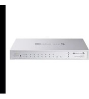


- CONTENTS
- PREFACE
- CHAPTER 1 USING THE CLI
- CHAPTER 2 LINE COMMANDS (ONLY FOR CERTAIN DEVICES)
- CHAPTER 3 USER INTERFACE
- CHAPTER 4 USER MANAGEMENT COMMANDS
- CHAPTER 5 SYSTEM CONFIGURATION COMMANDS
- CHAPTER 6 FILE SYSTEM CONFIGURATION COMMANDS (ONLY FOR CERTAIN DEVICES)
- CHAPTER 7 MANAGEMENT PORT CONFIGURATION COMMANDS (ONLY FOR CERTAIN DEVICES)
- CHAPTER 8 EEE CONFIGURATION COMMANDS
- CHAPTER 9 SDM TEMPLATE COMMANDS
- CHAPTER 10 TIME RANGE COMMANDS
- CHAPTER 11 PORT CONFIGURATION COMMANDS
- CHAPTER 12 PORT ISOLATION COMMANDS
- CHAPTER 13 LOOPBACK DETECTION COMMANDS
- CHAPTER 14 STACK COMMANDS (ONLY FOR CERTAIN DEVICES)
- CHAPTER 15 DDM COMMANDS (ONLY FOR CERTAIN DEVICES)
- CHAPTER 16 ETHERCHANNEL COMMANDS
- CHAPTER 17 MAC ADDRESS COMMANDS
- CHAPTER 18 IEEE 802.1Q VLAN COMMANDS
- CHAPTER 19 MAC-BASED VLAN COMMANDS
- CHAPTER 20 PROTOCOL-BASED VLAN COMMANDS
- CHAPTER 21 PRIVATE VLAN COMMANDS (ONLY FOR CERTAIN DEVICES)
- CHAPTER 22 VLAN-VPN COMMANDS (ONLY FOR CERTAIN DEVICES)
- CHAPTER 23 ERPS COMMANDS
- CHAPTER 24 GVRP COMMANDS
- CHAPTER 25 IGMP SNOOPING COMMANDS
- CHAPTER 26 LAYER 3 IGMP COMMANDS (ONLY FOR CERTAIN DEVICES)
- CHAPTER 27 PIM COMMANDS (ONLY FOR CERTAIN DEVICES)
- CHAPTER 28 STATIC MULTICAST ROUTING COMMANDS (ONLY FOR CERTAIN DEVICES)
- CHAPTER 29 MLD SNOOPING COMMANDS
- CHAPTER 30 MVR COMMANDS
- CHAPTER 31 MSTP COMMANDS
- CHAPTER 32 DEBUG COMMANDS
- CHAPTER 33 LLDP COMMANDS
- CHAPTER 34 L2PT COMMANDS (ONLY FOR CERTAIN DEVICES)
- CHAPTER 35 PPPOE ID-INSERTION COMMANDS (ONLY FOR CERTAIN DEVICES)
- CHAPTER 36 STATIC ROUTES COMMANDS
- CHAPTER 37 RIP CONFIGURATION COMMANDS (ONLY FOR CERTAIN DEVICES)
- CHAPTER 38 RIPNG CONFIGURATION COMMANDS (ONLY FOR CERTAIN DEVICES)
- CHAPTER 39 OSPF CONFIGURATION COMMANDS (ONLY FOR CERTAIN DEVICES)
- CHAPTER 40 OSPFV3 CONFIGURATION COMMANDS (ONLY FOR CERTAIN DEVICES)
- CHAPTER 41 BFD CONFIGURATION COMMANDS (ONLY FOR CERTAIN DEVICES)
- CHAPTER 42 BGP CONFIGURATION COMMANDS (ONLY FOR CERTAIN DEVICES)
- CHAPTER 43 IS-IS CONFIGURATION COMMANDS (ONLY FOR CERTAIN DEVICES)
- CHAPTER 44 URPF CONFIGURATION COMMANDS (ONLY FOR CERTAIN DEVICES)
- CHAPTER 45 TUNNEL CONFIGURATION COMMANDS (ONLY FOR CERTAIN DEVICES)
- CHAPTER 46 IPV6 ADDRESS CONFIGURATION COMMANDS
- CHAPTER 47 ARP COMMANDS
- CHAPTER 48 VRRP COMMANDS (ONLY FOR CERTAIN DEVICES)
- CHAPTER 49 DHCP SERVER COMMANDS
- CHAPTER 50 DHCP RELAY COMMANDS
- CHAPTER 51 DHCPV6 RELAY COMMANDS
- CHAPTER 52 DHCP L2 RELAY COMMANDS
- CHAPTER 53 DHCPV6 L2 RELAY COMMANDS
- CHAPTER 54 QOS COMMANDS
- CHAPTER 55 BANDWIDTH CONTROL COMMANDS
- CHAPTER 56 OUI-BASED VLAN COMMANDS (ONLY FOR CERTAIN DEVICES)
- CHAPTER 57 VOICE VLAN COMMANDS
- CHAPTER 58 AUTO VOIP COMMANDS
- CHAPTER 59 ACCESS CONTROL COMMANDS
- CHAPTER 60 HTTP AND HTTPS COMMANDS
- CHAPTER 61 SSH COMMANDS
- CHAPTER 62 TELNET COMMANDS
- CHAPTER 63 SERIAL PORT COMMANDS
- CHAPTER 64 AAA COMMANDS
- CHAPTER 65 IEEE 802.1X COMMANDS
- CHAPTER 66 PORT SECURITY COMMANDS (ONLY FOR CERTAIN DEVICES)
- CHAPTER 67 MACSEC COMMANDS (ONLY FOR CERTAIN DEVICES)
- CHAPTER 68 PORT MIRRORING COMMANDS
- CHAPTER 69 ACL COMMANDS
- CHAPTER 70 IPV4 IMPB COMMANDS
- CHAPTER 71 IPV6 IMPB COMMANDS
- CHAPTER 72 IP VERIFY SOURCE COMMANDS
- CHAPTER 73 IPV6 VERIFY SOURCE COMMANDS
- CHAPTER 74 DHCPV4 FILTER COMMANDS
- CHAPTER 75 DHCPV6 FILTER COMMANDS
- CHAPTER 76 DOS DEFEND COMMANDS
- CHAPTER 77 SFLOW COMMANDS (ONLY FOR CERTAIN DEVICES)
- CHAPTER 78 ETHERNET OAM COMMANDS (ONLY FOR CERTAIN DEVICES)
- CHAPTER 79 DLDP COMMANDS (ONLY FOR CERTAIN DEVICES)
- CHAPTER 80 SNMP COMMANDS
- CHAPTER 81 NETCONF COMMANDS (ONLY FOR CERTAIN DEVICES)
- CHAPTER 82 POE COMMANDS (ONLY FOR CERTAIN DEVICES)
- CHAPTER 83 ARP INSPECTION COMMANDS
- CHAPTER 84 ND DETECTION COMMANDS
- CHAPTER 85 SYSTEM LOG COMMANDS
- OVERVIEW OF THIS GUIDE
- CHAPTER 1: USING THE CLI
- CHAPTER 2: LINE COMMANDS (ONLY FOR CERTAIN DEVICES)
- CHAPTER 3: USER INTERFACE
- CHAPTER 4: USER MANAGEMENT COMMANDS
- CHAPTER 5: SYSTEM CONFIGURATION COMMANDS
- CHAPTER 6: FILE SYSTEM CONFIGURATION COMMANDS
- CHAPTER 7: MANAGEMENT PORT CONFIGURATION COMMANDS
- CHAPTER 8: EEE CONFIGURATION COMMANDS
- CHAPTER 9: SDM TEMPLATE COMMANDS
- CHAPTER 10: TIME RANGE COMMANDS
- CHAPTER 11: PORT CONFIGURATION COMMANDS
- CHAPTER 12: PORT ISOLATION COMMANDS
- CHAPTER 13: LOOPBACK DETECTION COMMANDS
- CHAPTER 14: STACK COMMANDS
- CHAPTER 15: DDM COMMANDS (ONLY FOR CERTAIN DEVICES)
- CHAPTER 16: ETHERCHANNEL COMMANDS
- CHAPTER 17: MAC ADDRESS COMMANDS
- CHAPTER 18: IEEE 802.1Q VLAN COMMANDS
- CHAPTER 19: MAC-BASED VLAN COMMANDS
- CHAPTER 20: PROTOCOL-BASED VLAN COMMANDS
- CHAPTER 21: PRIVATE VLAN COMMANDS (ONLY FOR CERTAIN DEVICES)
- CHAPTER 22: VLAN-VPN COMMANDS (ONLY FOR CERTAIN DEVICES)
- CHAPTER 23: ERPS COMMANDS
- CHAPTER 24: GVRP COMMANDS
- CHAPTER 25: IGMP SNOOPING COMMANDS
- CHAPTER 26: LAYER 3 IGMP COMMANDS (ONLY FOR CERTAIN DEVICES)
- CHAPTER 27: PIM COMMANDS (ONLY FOR CERTAIN DEVICES)
- CHAPTER 28: STATIC MULTICAST ROUTING COMMANDS (ONLY FOR CERTAIN DEVICES)
- CHAPTER 29: MLD SNOOPING COMMANDS
- CHAPTER 30: MVR COMMANDS
- CHAPTER 31: MSTP COMMANDS
- CHAPTER 32: DEBUG COMMANDS
- CHAPTER 33: LLDP COMMANDS
- CHAPTER 34: L2PT COMMANDS (ONLY FOR CERTAIN DEVICES)
- CHAPTER 35: PPPOE ID-INSERTION COMMANDS (ONLY FOR CERTAIN DEVICES)
- CHAPTER 36: STATIC ROUTES COMMANDS
- CHAPTER 37: RIP CONFIGURATION COMMANDS
- CHAPTER 38: RIPNG CONFIGURATION COMMANDS
- CHAPTER 39: OSPF CONFIGURATION COMMANDS
- CHAPTER 40: OSPFV3 CONFIGURATION COMMANDS (ONLY FOR CERTAIN DEVICES)
- CHAPTER 41: BFD CONFIGURATION COMMANDS (ONLY FOR CERTAIN DEVICES)
- CHAPTER 42: BGP CONFIGURATION COMMANDS (ONLY FOR CERTAIN DEVICES)
- CHAPTER 43: IS-IS CONFIGURATION COMMANDS (ONLY FOR CERTAIN DEVICES)
- CHAPTER 44: URPF CONFIGURATION COMMANDS (ONLY FOR CERTAIN DEVICES)
- CHAPTER 45: TUNNEL CONFIGURATION COMMANDS (ONLY FOR CERTAIN DEVICES)
- CHAPTER 46: IPV6 ADDRESS CONFIGURATION COMMANDS
- CHAPTER 47: ARP CONFIGURATION COMMANDS
- CHAPTER 48: VRRP CONFIGURATION COMMANDS (ONLY FOR CERTAIN DEVICES)
- CHAPTER 49: DHCP SERVER CONFIGURATION COMMANDS
- CHAPTER 50: DHCP RELAY CONFIGURATION COMMANDS
- CHAPTER 51: DHCPV6 RELAY CONFIGURATION COMMANDS
- CHAPTER 52: DHCP L2 RELAY CONFIGURATION COMMANDS
- CHAPTER 53: DHCPV6 L2 RELAY CONFIGURATION COMMANDS
- CHAPTER 54: QOS CONFIGURATION COMMANDS
- CHAPTER 55: BANDWIDTH CONTROL CONFIGURATION COMMANDS
- CHAPTER 56: OUI-BASED VLAN CONFIGURATION COMMANDS (ONLY FOR CERTAIN DEVICES)
- CHAPTER 57: VOICE VLAN CONFIGURATION COMMANDS
- CHAPTER 58: AUTO VOIP CONFIGURATION COMMANDS
- CHAPTER 59: ACCESS CONTROL CONFIGURATION COMMANDS
- CHAPTER 60: HTTP AND HTTPS CONFIGURATION COMMANDS
- CHAPTER 61: SSH CONFIGURATION COMMANDS
- CHAPTER 62: TELNET CONFIGURATION COMMANDS
- CHAPTER 63: SERIAL PORT CONFIGURATION COMMANDS (ONLY FOR CERTAIN DEVICES)
- CHAPTER 64: AAA CONFIGURATION COMMANDS
- CHAPTER 65: IEEE 802.1X CONFIGURATION COMMANDS
- CHAPTER 66: PORT SECURITY CONFIGURATION COMMANDS
- CHAPTER 67: MACSEC CONFIGURATION COMMANDS (ONLY FOR CERTAIN DEVICES)
- CHAPTER 68: PORT MIRRORING CONFIGURATION COMMANDS
- CHAPTER 69: ACL CONFIGURATION COMMANDS
- CHAPTER 70: IPV4 IMPB CONFIGURATION COMMANDS
- CHAPTER 71: IPV6 IMPB CONFIGURATION COMMANDS
- CHAPTER 72: IP VERIFY SOURCE CONFIGURATION COMMANDS
- CHAPTER 73: IPV6 VERIFY SOURCE CONFIGURATION COMMANDS
- CHAPTER 74: DHCPV4 FILTER CONFIGURATION COMMANDS
- CHAPTER 75: DHCPV6 FILTER CONFIGURATION COMMANDS
- CHAPTER 76: DOS DEFEND CONFIGURATION COMMAND
- CHAPTER 77: SFLOW CONFIGURATION COMMANDS (ONLY FOR CERTAIN DEVICES)
- CHAPTER 78: ETHERNET OAM CONFIGURATION COMMANDS (ONLY FOR CERTAIN DEVICES)
- CHAPTER 79: DLDP COMMANDS CONFIGURATION (ONLY FOR CERTAIN DEVICES)
- CHAPTER 80: SNMP CONFIGURATION COMMANDS
- CHAPTER 81: NETCONF COMMANDS CONFIGURATION (ONLY FOR CERTAIN DEVICES)
- CHAPTER 82: POE COMMANDS CONFIGURATION (ONLY FOR CERTAIN DEVICES)
- CHAPTER 83: ARP INSPECTION CONFIGURATION COMMANDS
- CHAPTER 84: ND DETECTION CONFIGURATION COMMANDS
- CHAPTER 85: SYSTEM LOG CONFIGURATION COMMANDS
- ACCESSING THE CLI
- LOGON BY A CONSOLE PORT
- CONSOLE PORT
- USB CONSOLE DRIVER
- LOGON BY TELNET
- LOGON BY SSH
- NOTE
- PASSWORD AUTHENTICATION MODE
- KEY AUTHENTICATION MODE
- CLI COMMAND MODES
- PRIVILEGE RESTRICTIONS
- CONVENTIONS
- POE DISCLAIMER
- FORMAT CONVENTIONS
- SPECIAL CHARACTERS
- PARAMETER FORMAT
- LINE
- DESCRIPTION
- SYNTAX
- PARAMETER
- COMMAND MODE
- PRIVILEGE REQUIREMENT
- EXAMPLE
- MEDIA-TYPE RJ
- ENABLE
- SERVICE
- PASSWORD-ENCRYPTION
- ENABLE PASSWORD
- USER GUIDELINES
- ENABLE SECRET
- CONFIGURE
- EXIT
- END
- CLIPAGING
- HISTORY
- HISTORY CLEAR
- USER NAME (PASSWORD)
- USER NAME (SECRET)
- SERVICE PASSWORD-RECOVERY
- SHOW USER ACCOUNT-LIST
- SHOW USER CONFIGURATION
- SYSTEM-TIME MANUAL
- SYSTEM-TIME NTP
- SYSTEM-TIME DST PREDEFINED
- SYSTEM-TIME DST DATE
- SYSTEM-TIME DST RECURRING
- HOSTNAME
- LOCATION
- CONTACT-INFO
- LED
- IP ADDRESS
- IP ADDRESS-ALLOC
- CONTROLLER CLOUD-BASED (ONLY FOR
- CONTROLLER INFORM-URL (ONLY FOR
- RESET
- SERVICE RESET-DISABLE
- REBOOT
- REBOOT-SCHEDULE
- COPY RUNNING-CONFIG STARTUP-CONFIG
- COPY STARTUP-CONFIG TFTP
- COPY TFTP STARTUP-CONFIG
- COPY BACKUP-CONFIG TFTP
- COPY BACKUP-CONFIG STARTUP-CONFIG
- COPY RUNNING-CONFIG BACKUP-CONFIG
- COPY TFTP BACKUP-CONFIG
- BOOT APPLICATION
- BOOT CONFIG
- REMOVE BACKUP-IMAGE
- FIRMWARE UPGRADE
- PATCH LOAD (ONLY FOR CERTAIN DEVICES)
- PATCH ACTIVE (ONLY FOR CERTAIN DEVICES)
- PATCH RUN (ONLY FOR CERTAIN DEVICES)
- PATCH DEACTIVE (ONLY FOR CERTAIN DEVICES)
- PATCH UNINSTALL (ONLY FOR CERTAIN DEVICES)
- THIS COMMAND IS USED TO UNINSTALL A RUNNING PATCH AND ACTIVATE IT
- PATCH UNINSTALL
- PATCH DELETE (ONLY FOR CERTAIN DEVICES)
- SHOW PATCH INFORMATION (ONLY FOR CERTAIN DEVICES)
- THIS COMMAND IS USED TO VIEW THE PATCH INFORMATION OF THE CURRENT SYSTEM
- SHOW PATCH INFORMATION
- NONE
- MCU-FIRMWARE UNIT UPGRADE
- MCU-FIRMWARE TYPE (ONLY FOR CERTAIN DEVICES)
- CHECKPOINT FILE (ONLY FOR CERTAIN
- DEVICES)
- SHOW CHECKPOINT (ONLY FOR CERTAIN
- ROLLBACK RUNNING-CONFIG FILE
- BOOT AUTOINSTALL START
- BOOT AUTOINSTALL
- PERSISTENT-MODE
- BOOT AUTOINSTALL AUTO-SAVE
- AUTO-REBOOT
- BOOT AUTOINSTALL RETRY-COUNT
- SHOW BOOT AUTOINSTALL
- SHOW BOOT AUTOINSTALL DOWNLOADED-CONFIG
- PING
- TRACERT
- SWITCH# TRACERT
- SWITCH# TRACERT FE
- SHOW SYSTEM-INFO
- SHOW IMAGE-INFO
- SHOW BOOT
- SHOW RUNNING-CONFIG
- UNIT — SPECIFY THE UNIT NUMBER OF A SWITCH TO SHOW THE UNIT'S OPERATING CONFIGURATIONS. BY DEFAULT, IT IS
- SHOW STARTUP-CONFIG
- SHOW SYSTEM-TIME
- SHOW SYSTEM-TIME DST
- SHOW SYSTEM-TIME NTP
- SHOW CABLE-DIAGNOSTICS INTERFACE
- SHOW CPU-UTILIZATION
- SHOW MEMORY-UTILIZATION
- SHOW CONTROLLER
- SHOW TEMPERATURE
- SHOW VOLTAGE
- CLEAR CONFIG INTERFACE
- POWER BACKUP UNIT (ONLY FOR
- CERTAIN DEVICES)
- SHOW POWER (ONLY FOR CERTAIN DEVICES)
- CHAPTER 6 FILE SYSTEM CONFIGURATION COMMANDS
- COPY
- CD
- DIR
- PWD
- RENAME
- DELETE
- FTP
- OPEN
- PUT
- GET
- CLOSE
- CHAPTER 7 MANAGEMENT PORT CONFIGURATION
- COMMANDS (ONLY FOR CERTAIN DEVICES)
- MANAGEMENT-PORT PROTOCOL
- MANAGEMENT-PORT IP
- MANAGEMENT-PORT IPV6 ENABLE
- MANAGEMENT-PORT IPV
- ADDRESS
- SHOW MANAGEMENT-PORT
- EEE
- SHOW INTERFACE EEE
- SDM PREFER
- SHOW SDM PREFER
- TIME-RANGE
- ABSOLUTE
- PERIODIC
- HOLIDAY (TIME-RANGE MODE)
- HOLIDAY
- SHOW HOLIDAY
- SHOW TIME-RANGE
- INTERFACE
- INTERFACE RANGE
- SHUTDOWN
- FLOW-CONTROL
- DUPLEX
- JUMBO-SIZE
- SPEED
- CLEAR COUNTERS
- SHOW FIBER-PORTS
- SHOW INTERFACE STATUS
- SHOW INTERFACE COUNTERS
- SHOW INTERFACE CONFIGURATION
- PORT ISOLATION
- SHOW PORT ISOLATION INTERFACE
- LOOPBACK-DETECTION (GLOBAL)
- LOOPBACK-DETECTION INTERVAL
- LOOPBACK-DETECTION RECOVERY-TIME
- LOOPBACK-DETECTION
- (INTERFACE)
- LOOPBACK-DETECTION CONFIG
- PROCESS-MODE
- RECOVER
- SHOW LOOPBACK-DETECTION GLOBAL
- SHOW LOOPBACK-DETECTION INTERFACE
- SWITCH# SHOW LOOPBACK-DETECTION INTERFACE
- SWITCH STACK-NAME
- SWITCH STACK-GROUP
- GROUP-INFO
- INTERFACE PORT
- SWITCH PRIORITY
- SWITCH RENUMBER
- SWITCH(CONFIG)# SWITCH 1 RENUMBER
- SWITCH PROVISION
- SWITCH MAC-DELAY
- SWITCH MAC-DELAY SHOW
- SHOW SWITCH STACK-PORTS
- SHOW SWITCH
- SHOW SWITCH NEIGHBORS
- DDM STATE ENABLE
- DEFAULT SETTING
- DDM SHUTDOWN
- DDM
- TEMPERATURE_THRESHOLD
- DDM VOLTAGE_THRESHOLD
- HIGH_ALARM — SPECIFY THE HIGHEST THRESHOLD FOR THE ALARM. WHEN THE OPERATING PARAMETER RISES ABOVE THE VALUE HEREINAFTER, ACTION ASSOCIATED WITH THE ALARM WILL BE TAKEN
- BIAS_CURRENT_THRESHOLD
- DDM TX_POWER_THRESHOLD
- DDM RX_POWER_THRESHOLD
- SHOW DDM CONFIGURATION
- SHOW DDM STATUS
- CHANNEL-GROUP
- PORT-CHANNEL LOAD-BALANCE
- LACP SYSTEM-PRIORITY
- LACP PORT-PRIORITY
- SHOW ETHERCHANNEL
- SHOW ETHERCHANNEL LOAD-BALANCE
- SHOW LACP
- SHOW LACP SYS-ID
- MAC ADDRESS-TABLE STATIC
- NO MAC ADDRESS-TABLE DYNAMIC
- MAC ADDRESS-TABLE AGING-TIME
- MAC ADDRESS-TABLE FILTERING
- MAC ADDRESS-TABLE NOTIFICATION
- NOTE: THIS COMMAND IS ONLY AVAILABLE ON CERTAIN DEVICES
- THE MAC ADDRESS-TABLE NOTIFICATION COMMAND IS USED TO CONFIGURE GLOBAL SETTINGS OF MAC ADDRESS TABLE NOTIFICATION
- MAC ADDRESS-TABLE NOTIFICATION { [ GLOBAL-STATUS ENABLE | DISABLE ] [ TABLE-FULL-STATUS ENABLE | DISABLE ] [ INTERVAL TIME ] }
- GLOBAL-STATUS ENABLE | DISABLE — ENABLE/DISABLE THE NOTIFICATION FUNCTION GLOBALLY
- MAC ADDRESS-TABLE
- MAX-MAC-COUNT
- NOTIFICATION (INTERFACE)
- MAC ADDRESS-TABLE SECURITY
- VLAN-SECURITY
- SHOW MAC ADDRESS-TABLE
- CLEAR MAC ADDRESS-TABLE
- SHOW MAC ADDRESS-TABLE AGING-TIME
- SHOW MAC ADDRESS-TABLE INTERFACE
- SHOW MAC ADDRESS-TABLE COUNT
- SHOW MAC ADDRESS-TABLE ADDRESS
- SHOW MAC ADDRESS-TABLE VLAN
- SHOW MAC ADDRESS-TABLE NOTIFICATION
- SHOW MAC ADDRESS-TABLE SECURITY
- VLAN
- NAME
- VLAN_TRUNK (GLOBALLY)
- VLAN_TRUNK (INTERFACE)
- SWITCHPORT GENERAL ALLOWED VLAN
- SWITCHPORT PVID
- SWITCHPORT CHECK INGRESS
- SWITCHPORT ACCEPTABLE FRAME
- SHOW VLAN SUMMARY
- SHOW VLAN BRIEF
- SHOW VLAN
- SHOW INTERFACE SWITCHPORT
- MAC-VLAN MAC-ADDRESS
- MAC-VLAN
- SHOW MAC-VLAN
- SHOW MAC-VLAN INTERFACE
- PROTOCOL-VLAN TEMPLATE
- PROTOCOL-VLAN VLAN
- PROTOCOL-VLAN GROUP
- SHOW PROTOCOL-VLAN TEMPLATE
- SHOW PROTOCOL-VLAN VLAN
- PRIVATE-VLAN PRIMARY
- PRIVATE-VLAN COMMUNITY
- PRIVATE-VLAN ISOLATED
- PRIVATE-VLAN ASSOCIATION
- SWITCHPORT PRIVATE-VLAN
- SWITCHPORT PRIVATE-VLAN HOST-ASSOCIATION
- SWITCHPORT PRIVATE-VLAN MAPPING
- SHOW VLAN PRIVATE-VLAN
- SHOW VLAN PRIVATE-VLAN INTERFACE
- DOT1Q-TUNNEL
- SWITCHPORT DOT1Q-TUNNEL TPID
- DOT1Q-TUNNEL MAPPING
- SWITCHPORT DOT1Q-TUNNEL MODE
- SWITCHPORT DOT1Q-TUNNEL MISSDROP (ONLY FOR CERTAIN DEVICES)
- SWITCHPORT DOT1Q-TUNNEL USE_INNER_PRIORITY
- SWITCHPORT DOT1Q-TUNNEL MAPPING
- SWITCHPORT DOT1Q-TUNNEL REPLACE
- PARAMETERS
- SWITCHPORT DOT1Q-TUNNEL REPLACE-OUT
- SHOW DOT1Q-TUNNEL
- SHOW DOT1Q-TUNNEL MAPPING
- SHOW DOT1Q-TUNNEL INTERFACE
- ERPS RING
- CONTROL-VLAN
- GUARD-TIMER
- WTR-TIMER
- HOLDOFF-TIMER
- PROTECTED-INSTANCE
- RAPS-MEL
- REVERTIVE
- SUB-RING
- TC-NOTIFY ERPS
- TC-PROTECTION INTERVAL
- TC-PROTECTION THRESHOLD
- VERSION
- VIRTUAL-CHANNEL
- ERPS RING RPL
- ERPS RING PROTECT-SWITCH
- SHOW ERPS RING
- GVRP
- GVRP (INTERFACE)
- GVRP REGISTRATION
- GVRP TIMER
- SHOW GVRP INTERFACE
- SHOW GVRP GLOBAL
- IP IGMP SNOOPING (GLOBAL)
- IP IGMP SNOOPING VERSION
- IP IGMP SNOOPING DROP-UNKNOWN
- IP IGMP SNOOPING HEADER-VALIDATION
- IP IGMP SNOOPING VLAN-CONFIG
- IP IGMP SNOOPING
- VLAN-CONFIG
- (IMMEDIATE-LEAVE)
- (REPORT-SUPPRESSION)
- THIS COMMAND IS USED TO ENABLE THE IGMP REPORT SUPPRESSION FUNCTION FOR SPECIFIC VLANS. WHEN ENABLED, THE SWITCH WILL ONLY FORWARD THE FIRST IGMP REPORT MESSAGE FOR EACH MULTICAST GROUP TO THE IGMP QUERIER AND SUPPRESS SUBSEQUENT IGMP REPORT MESSAGES FOR THE SAME MULTICAST GROUP DURING ONE QUERY INTERVAL. THIS FEATURE PREVENTS DUPLICATE REPORT MESSAGES FROM BEING SENT TO THE IGMP QUERIER. TO DISABLE THE IGMP REPORT SUPPRESSION FUNCTION AND FORWARD ALL THE IGMP REPORTS TO THE LAYER 3 DEVICE IN SPECIFIC VLANS, PLEASE USE THE NO IP IGMP SNOOPING VLAN-CONFIG VLAN-ID-LIST REPORT-SUPPRESSION COMMAND. THIS FUNCTION IS DISABLED BY DEFAULT
- IP IGMP SNOOPING VLAN-CONFIG VLAN-ID-LIST REPORT-SUPPRESSION NO IP IGMP SNOOPING VLAN-CONFIG VLAN-ID-LIST REPORT-SUPPRESSION
- VLAN-ID-LIST — THE ID LIST OF THE VLAN DESIRED TO MODIFY CONFIGURATION, RANGING FROM 1 TO 4094, IN THE FORMAT OF
- (ROUTER-PORTS-FORBIDDEN)
- VLAN-CONFIG (RPORT INTERFACE)
- VLAN-CONFIG (STATIC)
- VLAN-CONFIG (QUERIER)
- IP IGMP SNOOPING (INTERFACE)
- MAX-GROUPS
- IMMEDIATE-LEAVE
- IP IGMP SNOOPING AUTHENTICATION
- IP IGMP SNOOPING ACCOUNTING
- IP IGMP PROFILE
- DENY
- PERMIT
- RANGE
- IP IGMP FILTER
- CLEAR IP IGMP SNOOPING STATISTICS
- SHOW IP IGMP SNOOPING
- SHOW IP IGMP SNOOPING VLAN
- SHOW IP IGMP SNOOPING GROUPS
- SHOW IP IGMP PROFILE
- IP IGMP (GLOBAL)
- IP IGMP (ON SPECIFIC PORTS)
- IP IGMP HEADER-VALIDATION
- IP IGMP VERSION
- IP IGMP
- LAST-MEMBER-QUERY-COUNT
- LAST-MEMBER-QUERY-INTERVAL
- IP IGMP QUERY-INTERVAL
- QUERY-MAX-RESPONSE-TIME
- IP IGMP ROBUSTNESS
- STARTUP-QUERY-INTERVAL
- SHOW IP IGMP
- SHOW IP IGMP GROUPS
- SHOW IP IGMP GROUPS INTERFACE
- SHOW IP IGMP GROUPS INTERFACE VLAN
- SHOW IP IGMP INTERFACE VLAN
- IP MULTICAST-ROUTING
- IP PIM (GLOBALLY)
- IP PIM (ON SPECIFIC PORTS)
- IP PIM BSR-CANDIDATE INTERFACE
- IP PIM RP-CANDIDATE INTERFACE
- IP PIM RP-ADDRESS
- IP PIM BSR-BORDER
- IP PIM SSM
- IP PIM DR-PRIORITY
- IP PIM HELLO-INTERVAL
- IP PIM JOIN-PRUNE-INTERVAL
- SHOW IP MULTICAST
- SHOW IP MROUTE
- SHOW IP PIM INTERFACE
- SHOW IP PIM NEIGHBOR
- SHOW IP PIM STATISTIC
- SHOW IP PIM BSR-ROUTER
- SHOW IP PIM RP-HASH
- THE IP MROUTE COMMAND IS USED TO ADD/MODIFY STATIC MULTICAST ROUTING ENTRIES GLOBALLY. TO DELETE THE SPECIFIED STATIC MULTICAST ROUTING ENTRY, PLEASE USE THE NO IP MROUTE COMMAND
- IP MROUTE { SOURCE-ADDRESS} {MASK} { RPF-ADDRESS} [DISTANCE]
- SOURCE-ADDRESS: IP ADDRESS OF THE MULTICAST SOURCE, IN THE FORMAT
- SHOW IP MROUTE STATIC
- IPV6 MLD SNOOPING (GLOBAL)
- IPV6 MLD SNOOPING
- DROP-UNKNOWN
- IPV6 MLD SNOOPING VLAN-CONFIG
- IPV6 MLD SNOOPING VLAN-CONFIG (QUERIER)
- IPV6 MLD SNOOPING (INTERFACE)
- IPV6 MLD SNOOPING MAX-GROUPS
- IPV6 MLD PROFILE
- IPV6 MLD FILTER
- CLEAR IPV6 MLD SNOOPING STATISTICS
- SHOW IPV6 MLD SNOOPING
- SHOW IPV6 MLD SNOOPING INTERFACE
- SHOW IPV6 MLD SNOOPING VLAN
- SHOW IPV6 MLD SNOOPING GROUPS
- SHOW IPV6 MLD PROFILE
- MVR (GLOBAL)
- MVR GROUP
- MVR MODE
- MVR QUERYTIME
- MVR VLAN
- MVR (INTERFACE)
- MVR TYPE
- MVR IMMEDIATE
- MVR VLAN (GROUP)
- MVR VLAN (RULE)
- MVR MODE DYNAMIC AUTO-ENABLE
- SHOW MVR
- SHOW MVR INTERFACE
- SHOW MVR MEMBERS
- DEBUG SPANNING-TREE
- SPANNING-TREE (GLOBAL)
- SPANNING-TREE (INTERFACE)
- SPANNING-TREE
- COMMON-CONFIG
- SPANNING-TREE MODE
- SPANNING-TREE MST CONFIGURATION
- INSTANCE
- REVISION
- SPANNING-TREE MST INSTANCE
- SPANNING-TREE MST
- SPANNING-TREE PRIORITY
- SPANNING-TREE TIMER
- SPANNING-TREE HOLD-COUNT
- SPANNING-TREE MAX-HOPS
- SPANNING-TREE BPDUFILTER
- SPANNING-TREE BPDUFLOOD
- SPANNING-TREE BPDUGUARD
- SPANNING-TREE GUARD LOOP
- SPANNING-TREE GUARD ROOT
- INTERFACE CONFIGURATION MODE (INTERFACE GIGABITETHERNET / INTERFACE RANGE GIGABITETHERNET / INTERFACE PORT-CHANNEL / INTERFACE RANGE PORT-CHANNEL)
- ONLY ADMIN, OPERATOR AND POWER USER LEVEL USERS HAVE ACCESS TO THESE COMMANDS
- ENABLE THE ROOT PROTECT FUNCTION FOR PORT
- SPANNING-TREE GUARD TC
- SPANNING-TREE MCHECK
- SHOW SPANNING-TREE ACTIVE
- SHOW SPANNING-TREE BRIDGE
- SHOW SPANNING-TREE INTERFACE
- SHOW SPANNING-TREE INTERFACE-SECURITY
- SHOW SPANNING-TREE MST
- DEBUG TPPACKET
- PACKET-PRINT (ONLY FOR CERTAIN DEVICES)
- LLDP
- LLDP FORWARD_MESSAGE
- LLDP HOLD-MULTIPLIER
- LLDP TIMER
- LLDP RECEIVE
- LLDP TRANSMIT
- LLDP SNMP-TRAP
- LLDP TLV-SELECT
- LLDP MANAGEMENT-ADDRESS
- LLDP MED-FAST-COUNT
- LLDP MED-STATUS
- LLDP MED-TLV-SELECT
- LLDP MED-LOCATION
- SHOW LLDP
- SHOW LLDP INTERFACE
- SHOW LLDP LOCAL-INFORMATION INTERFACE
- NEIGHBOR-INFORMATION
- SHOW LLDP TRAFFIC INTERFACE
- L2PROTOCOL-TUNNEL
- L2PROTOCOL-TUNNEL TYPE
- SHOW L2PROTOCOL-TUNNEL GLOBAL
- SHOW L2PROTOCOL-TUNNEL INTERFACE
- L2PROTOCOL-TUNNEL DST-MAC
- SHOW L2PROTOCOL-TUNNEL DST-MAC
- PPPOE ID-INSERTION (GLOBAL)
- PPPOE CIRCUIT-ID (INTERFACE)
- PPPOE CIRCUIT-ID TYPE
- PPPOE REMOTE-ID
- SHOW PPPOE ID-INSERTION GLOBAL
- SHOW PPPOE ID-INSERTION INTERFACE
- SWITCH# SHOW PPPOE ID-INSERTION INTERFACE
- IP ROUTING
- INTERFACE VLAN
- INTERFACE LOOPBACK
- SWITCHPORT
- PORT-CHANNEL
- INTERFACE PORT-CHANNEL
- IP ROUTE
- IPV6 ROUTING
- IPV6 ROUTE
- SHOW INTERFACE VLAN
- SHOW IP INTERFACE
- SHOW IP INTERFACE BRIEF
- SHOW IP ROUTE
- SHOW IP ROUTE SPECIFY
- SHOW IP ROUTE SUMMARY
- SHOW IPV6 INTERFACE
- SHOW IPV6 ROUTE
- SHOW IPV6 ROUTE SUMMARY
- RIP (ROUTING INFORMATION PROTOCOL) IS A ROUTING PROTOCOL SUITABLE FOR SMALL NETWORKS AND HAS LOWER REQUIREMENTS IN TERMS OF BANDWIDTH, CONFIGURATION, AND MANAGEMENT. AS A ROUTING PROTOCOL BASED ON DISTANCE VECTOR ALGORITHM, RIP USES HOP COUNT AS THE MEASUREMENT STANDARD
- THIS ROUTER RIP COMMAND IS USED TO ENABLE THE RIP FUNCTION ON THE SWITCH. TO DISABLE THIS FUNCTION, PLEASE USE THE NO ROUTER RIP COMMAND
- NETWORK
- TIMER BASIC
- DISTANCE
- AUTO-SUMMARY
- DEFAULT-METRIC
- REDISTRIBUTE
- ALLOW-ECMP
- DEFAULT-INFORMATION ORIGINATE
- NEIGHBOR
- PASSIVE-INTERFACE
- IP RIP AUTHENTICATION MODE
- IP RIP AUTHENTICATION STRING
- IP RIP AUTHENTICATION
- KEY-CHAIN
- IP RIP RECEIVE VERSION
- IP RIP SEND VERSION
- IP RIP SPLIT-HORIZON
- IP RIP V2-BROADCAST
- SHOW IP RIP
- SHOW IP RIP STATUS
- CLEAR IP RIP
- CHAPTER 38 RIPNG CONFIGURATION COMMANDS (ONLY FOR
- ROUTER RIPNG
- IPV6 RIP ENABLE
- SHOW IPV6 RIP
- SHOW IPV6 RIP STATUS
- CLEAR IPV6 RIP
- OSPF IS AN INTERIOR GATEWAY PROTOCOL (IGP) DESIGNED EXPRESSLY FOR IP NETWORKS, SUPPORTING IP SUBNETTING AND TAGGING OF EXTERNALLY DERIVED ROUTING INFORMATION. OSPF ALSO ALLOWS PACKET AUTHENTICATION AND USES IP MULTICAST WHEN SENDING AND RECEIVING PACKETS
- THIS ROUTER OSPF COMMAND IS USED TO CREATE AN OSPF ROUTING PROCESS AND ENTER THE ROUTER CONFIGURATION MODE. EACH OSPF ROUTING PROCESS IS AN INDEPENDENT INSTANCE RUNNING THE OSPF PROTOCOL, AND THEY WORKS SEPARATELY. TO DELETE THE SPECIFIED OSPF ROUTING PROCESS, PLEASE USE THE NO ROUTER OSPF COMMAND
- ROUTER OSPF PROCESS-ID
- ROUTER-ID
- MAXIMUM-PATHS
- AUTO-COST
- TIMERS THROTTLE SPF
- COMPATIBLE RFC
- AREA STUB
- AREA NSSA
- AREA DEFAULT-COST
- AREA RANGE
- AREA AUTHENTICATION
- AREA VIRTUAL-LINK
- AUTHENTICATION
- AREA TRANSIT-AREA VIRTUAL-LINK ROUTER-ID AUTHENTICATION [ MESSAGE-DIGEST | NULL ]
- TRANSIT-AREA: THE TRANSITION AREA ID IN THE FORMAT OF AN IP ADDRESS IN DOTTED DECIMAL NOTATION OR DECIMAL VALUE RANGING FROM 1 TO
- AREA VIRTUAL-LINK AUTHENTICATION-KEY
- AREA VIRTUAL-LINK MESSAGE-DIGEST-KEY
- CAPABILITY OPAQUE
- GRACEFUL-RESTART
- GRACEFUL-RESTART GRACE-PERIOD
- GRACEFUL-RESTART HELPER
- GRACEFUL-RESTART HELPER PLANNED-ONLY
- GRACEFUL-RESTART HELPER STRICT-LSA-CHECKING
- IP OSPF COST
- IP OSPF RETRANSMIT-INTERVAL
- INTERVAL — THE RETRANSMIT INTERVAL, RANGING FROM 1 TO 65535 SECONDS. THE DEFAULT VALUE IS 5 SECONDS
- IP OSPF TRANSMIT-DELAY
- IP OSPF PRIORITY
- IP OSPF HELLO-INTERVAL
- IP OSPF DEAD-INTERVAL
- IP OSPF AUTHENTICATION
- IP OSPF AUTHENTICATION-KEY
- IP OSPF MESSAGE-DIGEST-KEY
- IP OSPF NETWORK
- IP OSPF PASSIVE
- CLEAR IP OSPF
- SHOW IP OSPF
- SHOW IP OSPF DATABASE
- SHOW IP OSPF INTERFACE
- SHOW IP OSPF NEIGHBOR
- BORDER-ROUTERS
- SHOW IP OSPF ROUTE
- SHOW IP OSPF [PROCESS-ID] GRACEFUL-RESTART HELPER
- THE IPV6 ROUTER OSPF COMMAND IS USED TO ENABLE AN OSPFV3 ROUTING PROCESS AND ENTER THE ROUTER CONFIGURATION MODE. TO DELETE THE SPECIFIED OSPFV3 ROUTING PROCESS, PLEASE USE THE NO IPV6 ROUTER OSPF COMMAND
- DISTANCE OSPF
- TIMERS ISA ARRIVAL
- IPV6 OSPF AREA
- IPV6 OSPF COST
- IPV6 OSPF
- RETRANSMIT-INTERVAL
- IPV6 OSPF TRANSMIT-DELAY
- IPV6 OSPF PRIORITY
- IPV6 OSPF HELLO-INTERVAL
- IPV6 OSPF DEAD-INTERVAL
- IPV6 OSPF NETWORK
- IPV6 OSPF MTU-IGNORE
- IPV6 OSPF PASSIVE
- CLEAR IPV6 OSPF
- SHOW IPV6 OSPF
- SHOW IPV6 OSPF DATABASE
- SHOW IPV6 OSPF INTERFACE
- SHOW IPV6 OSPF NEIGHBOR
- SHOW IPV6 OSPF BORDER-ROUTERS
- SHOW IPV6 OSPF RIB
- CHAPTER 41 BFD CONFIGURATION COMMANDS (ONLY FOR CERTAIN
- BFD-TEMPLATE
- DETECT-MULTIPLIER
- RECEIVE-INTERVAL
- TRANSMIT-INTERVAL
- PASSIVE-MODE
- IP OSPF BFD
- IP OSPF BFD TEMPLATE
- IPV6 OSPF BFD
- ISIS BFD
- SHOW BFD COUNTERS
- SHOW BFD NEIGHBORS
- ROUTER BGP
- AGGREGATE-ADDRESS
- DISTANCE BGP
- TIMERS BGP
- BGP ALWAYS-COMPARE-MED
- BGP BESTPATH AS-PATH CONFED
- BGP BESTPATH AS-PATH IGNORE
- BGP BESTPATH AS-PATH MULTIPATH-RELAX
- BGP BESTPATH COMPARE-ROUTERID
- BGP BESTPATH MED CONFED
- BGP BESTPATH MED MISSING-AS-WORST
- BGP CLIENT-TO-CLIENT
- REFLECTION
- BGP CLUSTER-ID
- BGP CONFEDERATION PEERS
- BGP DAMPENING
- BGP DEFAULT IPV4-UNICAST
- BGP DEFAULT
- LOCAL-PREFERENCE
- BGP DETERMINISTIC-MED
- BGP ENFORCE-FIRST-AS
- BGP FAST-EXTERNAL-FAILOVER
- BGP NETWORK IMPORT-CHECK
- BGP ROUTER-ID
- NEIGHBOR ACTIVATE
- NEIGHBOR ADVERTISEMENT-INTERVAL
- NEIGHBOR ALLOWAS-IN
- ATTRIBUTE-UNCHANGED
- NEIGHBOR CAPABILITY DYNAMIC
- NEIGHBOR DEFAULT-ORIGINATE
- NEIGHBOR DESCRIPTION
- DISABLE-CONNECTED-CHECK
- NEIGHBOR DISTRIBUTE-LIST
- DONT-CAPABILITY-NEGOTIATE
- NEIGHBOR EBGP-MULTIHOP
- NEIGHBOR LOCAL-AS
- NEIGHBOR MAXIMUM-PREFIX
- NEIGHBOR NEXT-HOP-SELF
- NEIGHBOR OVERRIDE-CAPABILITY
- NEIGHBOR PASSIVE
- NEIGHBOR PASSWORD
- NEIGHBOR PEER-GROUP
- NEIGHBOR PORT
- NEIGHBOR REMOTE-AS
- REMOVE-PRIVATE-AS
- ROUTE-REFLECTOR-CLIENT
- NEIGHBOR SHUTDOWN
- SOFT-RECONFIGURATION INBOUND
- STRICT-CAPABILITY-MATCH
- NEIGHBOR TIMERS
- NEIGHBOR TIMERS CONNECT
- NEIGHBOR TTL-SECURITY HOPS
- NEIGHBOR UPDATE-SOURCE
- NEIGHBOR WEIGHT
- SHOW IP BGP
- SHOW IP BGP ATTRIBUTE-INFO
- SHOW IP BGP CIDR-ONLY
- SHOW IP BGP DAMPENING FLAP-STATISTICS
- SHOW IP BGP DAMPENING DAMPENED-PATHS
- SHOW IP BGP DAMPENING PARAMETERS
- SHOW IP BGP NEIGHBORS
- SHOW IP BGP NEIGHBORS ADVERTISED-ROUTES
- SHOW IP BGP NEIGHBORS FLAP-STATISTICS
- SHOW IP BGP NEIGHBORS PREFIX-COUNTS
- SHOW IP BGP NEIGHBORS RECEIVED-ROUTES
- SHOW IP BGP NEIGHBORS ROUTES
- SHOW IP BGP NEXTHOP
- SHOW IP BGP PATHS
- SHOW IP BGP SPECIFY
- SHOW IP BGP SUMMARY
- CLEAR IP BGP
- CLEAR IP BGP ALL
- CLEAR IP BGP DAMPENING
- CHAPTER 43 IS-IS CONFIGURATION COMMANDS (ONLY FOR CERTAIN
- ROUTER ISIS
- AREA-PASSWORD
- DOMAIN-PASSWORD
- IS-TYPE
- LOG-ADJACENCY-CHANGES
- LSP-GEN-INTERVAL
- LSP-MTU
- LSP-REFRESH-INTERVAL
- MAX-LSP-LIFETIME
- METRIC-STYLE
- NET
- PURGE-ORIGINATOR
- SET-ATTACHED-BIT
- SET-OVERLOAD-BIT
- SPF PREFIX-PRIORITY
- CLEAR ISIS NEIGHBOR
- IP ROUTER ISIS
- ISIS CIRCUIT-TYPE
- ISIS CSNP-INTERVAL
- ISIS HELLO-INTERVAL
- ISIS HELLO-MULTIPLIER
- ISIS METRIC
- ISIS NETWORK POINT-TO-POINT
- ISIS PASSIVE
- ISIS PASSWORD-KEY
- ISIS PRIORITY
- ISIS THREE-WAY-HANDSHAKE
- SHOW ISIS DATABASE
- SHOW ISIS HOSTNAME
- SHOW ISIS NEIGHBOR
- SHOW ISIS ROUTE
- SHOW ISIS SUMMARY
- SHOW ISIS INTERFACE
- UNICAST REVERSE PATH FORWARDING (URPF) AIMS TO PREVENT NETWORK ATTACKS BASED ON SOURCE IP ADDRESS SPOOFING. TO SAFEGUARD AGAINST FORGED IP PACKET ATTACKS ON THE NETWORK, AT THE NETWORK INGRESS POINT, THE ORIGIN OF IP PACKETS IS VERIFIED. IF THE SOURCE IS SUSPICIOUS, THE PACKET IS DROPPED DIRECTLY; IF IT PASSES THE URPF CHECK, THE IP PACKET IS ALLOWED TO ENTER
- THIS COMMAND IS USED TO ENABLE OR DISABLE THE URPF FEATURE. WHEN ENABLED, IT RETRIEVES THE PREVIOUSLY CONFIGURED FILTERING MODE FOR SECURITY CHECKS. IF NO MODE WAS PREVIOUSLY CONFIGURED, IT PERFORMS SECURITY CHECKS BASED ON THE DEFAULT STRICT-VLAN FILTERING MODE. DISABLING THE URPF FEATURE WILL NOT MODIFY THE SET FILTERING MODE FOR WHEN URPF WAS DISABLED
- URPF { ENABLE| DISABLE }
- GLOBAL CONFIGURATION MODE
- URPF MODE
- INTERFACE TUNNEL
- TUNNEL MODE
- TUNNEL DESTINATION
- TUNNEL TTL
- TUNNEL IP ADDRESS
- IPV6 ROUTE TUNNEL
- SHOW INTERFACE TUNNEL
- IPV6 ENABLE
- IPV6 ADDRESS AUTOCONFIG
- CONFIGURATION MODE
- IPV6 ADDRESS LINK-LOCAL
- IPV6 ADDRESS DHCP
- IPV6 ADDRESS RA
- IPV6 ADDRESS EUI
- IPV6 ADDRESS
- ARP
- CLEAR ARP-CACHE
- ARP DYNAMICRENEW
- ARP TIMEOUT
- GRATUITOUS-ARP
- INTF-STATUS-UP ENABLE
- DUP-IP-DETECTED ENABLE
- GRATUITOUS-ARP LEARNING ENABLE
- GRATUITOUS-ARP SEND-INTERVAL
- IP PROXY-ARP
- IP LOCAL-PROXY-ARP
- SHOW ARP
- SHOW IP ARP (INTERFACE)
- SHOW IP ARP SUMMARY
- SHOW GRATUITOUS-ARP
- SHOW IP PROXY-ARP
- IP VRRP VRID
- IPV6 VRRP VRID
- AUTHENTICATION-MODE
- IP VRRP VRID DESCRIPTION
- IP VRRP VRID PREEMPT-MODE
- IP VRRP VRID PRIORITY
- IP VRRP VRID TIMER-ADVERTISE
- IP VRRP VRID TRACK
- IP VRRP VRID VERSION
- IP VRRP VRID VIRTUAL-IP
- IP VRRP VRID VIRTUAL-IP SECONDARY
- IPV6 VRRP VRID ADDRESS LINK-LOCAL
- IPV6 VRRP VRID ADDRESS
- SHOW IP VRRP
- SHOW IP VRRP STATISTICS
- CLEAR IP VRRP STATISTICS
- SERVICE DHCP SERVER
- IP DHCP SERVER
- EXTEND-OPTION
- CAPWAP-AC-IP
- VENDOR-CLASS-ID
- IP DHCP SERVER EXCLUDED-ADDRESS
- IP DHCP SERVER POOL
- IP DHCP SERVER PING TIMEOUT
- IP DHCP SERVER PING PACKETS
- LEASE
- ADDRESS HARDWARE-ADDRESS
- ADDRESS CLIENT-IDENTIFIER
- DEFAULT-GATEWAY
- DNS-SERVER
- DHCP CONFIGURATION MODE
- NETBIOS-NAME-SERVER
- NETBIOS-NODE-TYPE
- NEXT-SERVER
- DOMAIN-NAME
- BOOTFILE
- OPTION
- SHOW IP DHCP SERVER STATUS
- SHOW IP DHCP SERVER STATISTICS
- SHOW IP DHCP SERVER EXTEND-OPTION
- SHOW IP DHCP SERVER POOL
- SHOW IP DHCP SERVER
- EXCLUDED-ADDRESS
- SHOW IP DHCP SERVER MANUAL-BINDING
- SHOW IP DHCP SERVER BINDING
- CLEAR IP DHCP SERVER STATISTICS
- CLEAR IP DHCP SERVER BINDING
- SERVICE DHCP RELAY
- IP DHCP RELAY HOPS
- HOPS — SPECIFIES THE MAXIMUM HOPS (DHCP RELAY AGENT) THAT THE DHCP PACKETS CAN BE RELAYED. IF A PACKET'S HOP COUNT IS MORE THAN THE VALUE YOU SET HERE, THE PACKET WILL BE DROPPED. THE VALID VALUE RANGES FROM 1 TO 16, AND THE DEFAULT VALUE IS
- IP DHCP RELAY TIME
- IP HELPER-ADDRESS
- IP DHCP RELAY INFORMATION OPTION
- IP DHCP RELAY INFORMATION STRATEGY
- IP DHCP RELAY INFORMATION FORMAT
- IP DHCP RELAY INFORMATION CIRCUIT-ID
- IP DHCP RELAY INFORMATION REMOTE-ID
- THE IP DHCP RELAY INFORMATION REMOTE-ID COMMAND IS USED TO SPECIFY THE CUSTOM REMOTE ID WHEN OPTION 82 CUSTOMIZATION IS ENABLED. TO CLEAR THE REMOTE ID, USE THE NO IP DHCP RELAY INFORMATION REMOTE-ID COMMAND
- IP DHCP RELAY INFORMATION REMOTE-ID REMOTEID
- REMOTEID — SPECIFY THE REMOTE ID, RANGING FROM 1 TO 64 CHARACTERS
- IP DHCP RELAY
- DEFAULT-INTERFACE
- IP DHCP RELAY VLAN
- SHOW IP DHCP RELAY
- IPV6 DHCP RELAY
- IPV6 DHCP RELAY VLAN 1 HELPER-ADDRESS
- IPV6 DHCP RELAY INFORMATION OPTION
- SWITCH(CONFIG-IF)# IPV6 DHCP RELAY INFORMATION
- OPTION18IPV6 DHCP RELAY
- INFORMATION OPTION
- IPV6 DHCP RELAY INFORMATION REMOTE-ID
- SHOW IPV6 DHCP RELAY
- SHOW IPV6 DHCP RELAY COUNTERS
- THE SHOW IPV6 DHCP RELAY COUNTERS COMMAND IS USED TO DISPLAY THE PACKET COUNTER OF THE DHCPV6 RELAY
- PRIVILEGED EXEC MODE AND ANY CONFIGURATION MODE
- DISPLAY THE PACKET COUNTER OF THE DHCPV6 RELAY
- IP DHCP L2RELAY
- IP DHCP L2RELAY VLAN
- IP DHCP L2RELAY INFORMATION OPTION
- IP DHCP L2RELAY INFORMATION STRATEGY
- IP DHCP L2RELAY INFORMATION FORMAT
- IP DHCP L2RELAY INFORMATION CIRCUIT-ID
- IP DHCP L2RELAY INFORMATION REMOTE-ID
- SHOW IP DHCP L2RELAY
- IPV6 DHCP L2RELAY
- IPV6 DHCP L2RELAY VLAN
- IPV6 DHCP L2RELAY INFORMATION OPTION
- IPV6 DHCP L2RELAY INFORMATION REMOTE-ID
- SHOW IPV6 DHCP L2RELAY INTERFACE
- QOS TRUST MODE
- QOS PORT-PRIORITY
- QOS COS-MAP
- QOS DOT1P-REMAP
- QOS DSCP-MAP
- QOS DSCP-REMAP
- QOS QUEUE BANDWIDTH
- QOS QUEUE MODE
- QOS LOCALPRI
- QOS COSPRI
- QOS DSCPPRI
- QOS WRED-PROFILE
- QOS WRED-BIND
- SHOW QOS WRED-PROFILE
- SHOW QOS WIRED-BIND INTERFACE
- SHOW QOS COS-MAP
- SHOW QOS DOT1P-REMAP INTERFACE
- SHOW QOS DOT1P-REMAP
- SHOW QOS DSCP-MAP
- SHOW QOS DSCP-REMAP INTERFACE
- SHOW QOS DSCP-REMAP
- SHOW QOS PORT-PRIORITY INTERFACE
- SHOW QOS TRUST INTERFACE
- SHOW QOS QUEUE INTERFACE
- STORM-CONTROL RATE-MODE
- STORM-CONTROL
- STORM-CONTROL EXCEED
- STORM-CONTROL RECOVER
- BANDWIDTH
- SHOW STORM-CONTROL
- SHOW BANDWIDTH
- VOICE VLAN
- VOICE-VLAN(INTERFACE)
- SHOW VOICE-VLAN
- VOICE VLAN (INTERFACE)
- VOICE VLAN PRIORITY
- VOICE VLAN OUI
- SHOW VOICE VLAN
- SHOW VOICE VLAN OUI-TABLE
- SHOW VOICE VLAN INTERFACE
- AUTO-VOIP
- AUTO-VOIP (INTERFACE)
- AUTO-VOIP DOT1P
- AUTO-VOIP UNTAGGED
- AUTO-VOIP NONE
- NO AUTO-VOIP (INTERFACE)
- AUTO-VOIP DSCP
- AUTO-VOIP DATA PRIORITY
- SHOW AUTO-VOIP
- USER ACCESS-CONTROL IP-BASED ENABLE
- USER ACCESS-CONTROL IP-BASED
- USER ACCESS-CONTROL MAC-BASED ENABLE
- USER ACCESS-CONTROL MAC-BASED
- USER ACCESS-CONTROL PORT-BASED ENABLE
- USER ACCESS-CONTROL PORT-BASED
- USER ACCESS-CONTROL IPV6-BASED ENABLE
- USER ACCESS-CONTROL IPV6-BASED
- IP HTTP SERVER
- IP HTTP PORT
- IP HTTP MAX-USERS
- IP HTTP SESSION TIMEOUT
- IP HTTP SECURE-SERVER
- IP HTTP SECURE-PORT
- IP HTTP SECURE-PROTOCOL
- IP HTTP SECURE-CIPHERSUITE
- IP HTTP SECURE-MAX-USERS
- ADMIN-NUM: THE MAXIMUM NUMBER OF USERS LOGGING ON TO THE HTTPS SERVER AS ADMIN, RANGING FROM 1 TO 16. THE TOTAL NUMBER OF USERS SHOULD BE LESS THAN
- ONLY ADMIN, OPERATOR, AND POWER USER LEVEL USERS HAVE ACCESS TO THESE COMMANDS
- IP HTTP SECURE-SESSION TIMEOUT
- IP HTTP SECURE-SERVER DOWNLOAD CERTIFICATE
- IP HTTP SECURE-SERVER DOWNLOAD KEY
- SHOW IP HTTP CONFIGURATION
- SHOW IP HTTP SECURE-SERVER
- IP SSH SERVER
- IP SSH PORT
- IP SSH ALGORITHM
- IP SSH ALGORITHM COMPATIBILITY
- SWITCH#IP SSH ALGORITHM COMPATIBILITY
- IP SSH TIMEOUT
- IP SSH MAX-CLIENT
- IP SSH DOWNLOAD
- REMOVE PUBLIC-KEY
- SHOW IP SSH
- TELNET
- TELNET ENABLE
- TELNET PORT
- SHOW TELNET-STATUS
- SERIAL_PORT BAUD-RATE
- TACACS-SERVER HOST
- SHOW TACACS-SERVER
- RADIUS-SERVER HOST
- RADIUS-SERVER
- RADSEC-PROFILE
- DOWNLOAD CA-CERTIFICATE
- DOWNLOAD CLIENT-CERTIFICATE
- DOWNLOAD CLIENT-KEY
- SHOW RADIUS-SERVER
- RADIUS-SERVER LOAD-BALANCE ALGORITHM
- RADIUS-SERVER LOAD-BALANCE LEAST-OUTSTADING
- RADIUS-SERVER DEAD-COUNT
- DEAD-COUNT: MAXIMUM NUMBER OF CONSECUTIVE NON-RESPONSES DURING THE RADIUS SERVER STATUS DETECTION PROCESS, RANGING FROM 1 TO 6, AND THE DEFAULT VALUE IS
- RADIUS-SERVER DEAD-CYCLE
- RADIUS-SERVER DEAD-INTERVAL
- RADIUS-SERVER DEAD-TIME
- MAX-UNRESPONSIVEINTERVAL
- RADIUS-SERVER TESTUSER
- RADIUS-SERVER DETECT-SERVER
- AAA GROUP
- SERVER
- SHOW AAA GROUP
- AAA AUTHENTICATION LOGIN
- AAA AUTHENTICATION ENABLE
- AAA AUTHENTICATION DOT1X DEFAULT
- AAA ACCOUNTING DOT1X DEFAULT
- SHOW AAA AUTHENTICATION
- SHOW AAA ACCOUNTING
- LINE TELNET
- LOGIN AUTHENTICATION (TELNET)
- LINE SSH
- LOGIN AUTHENTICATION (SSH)
- LINE CONSOLE
- LOGIN AUTHENTICATION
- (CONSOLE)
- ENABLE AUTHENTICATION (TELNET)
- ENABLE AUTHENTICATION (SSH)
- ENABLE AUTHENTICATION (CONSOLE)
- IP HTTP LOGIN AUTHENTICATION
- IP HTTP ENABLE AUTHENTICATION
- SHOW AAA GLOBAL
- ENABLE ADMIN PASSWORD
- ENABLE ADMIN SECRET
- ENABLE-ADMIN
- DOT1X SYSTEM-AUTH-CONTROL
- DOT1X HANDSHAKE
- DOT1X AUTH-PROTOCOL
- DOT1X VLAN-ASSIGNMENT
- DOT1X ACCOUNTING
- DOT1X MAB
- DOT1X GUEST-VLAN
- DOT1X TIMEOUT QUIET-PERIOD
- TIME — THE LENGTH OF THE QUIET-PERIOD TIME. IF ONE USER'S AUTHENTICATION FAILS, ITS SUBSEQUENT IEEE 802.1X AUTHENTICATION REQUESTS WILL NOT BE PROCESSED DURING THE QUIET-PERIOD TIME. IT RANGES FROM 1 TO 999 SECONDS AND THE DEFAULT VALUE IS 10 SECONDS
- INTERFACE CONFIGURATION MODE
- DOT1X TIMEOUT SUPP-TIMEOUT
- DOT1X MAX-REQ
- DOT1X
- DOT1X PORT-CONTROL
- DOT1X PORT-METHOD
- DOT1X AUTH-INIT
- DOT1X AUTH-REAUTH
- SHOW DOT1X GLOBAL
- SHOW DOT1X INTERFACE
- SHOW DOT1X AUTH-STATE INTERFACE
- MAX-MAC COUNT
- MAC ADDRESS-TABLE STICKY MAC
- MAC ADDRESS-TABLE STICKY SAVE-TIME
- THE MAC ADDRESS-TABLE STICKY SAVE-TIME COMMAND IS USED TO CONFIGURE THE INTERVAL FOR SAVING STICKY MAC. TO RESTORE THE DEFAULT CONFIGURATION, PLEASE USE THE NO MAC ADDRESS-TABLE STICKY SAVE-TIME COMMAND
- MAC ADDRESS-TABLE STICKY SAVE-TIME TIME
- TIME: THE INTERVAL FOR SAVING STICKY MAC, WHICH IS 600S BY DEFAULT
- MACSEC MKA-POLICY
- MACSEC APPLY-POLICY
- MACSEC CIPHER_SUITE
- MACSEC
- CONFIDENTIALITY-OFFSET
- MACSEC DESIRE
- MACSEC MKA
- MACSEC MKA PRIORITY
- MACSEC MKA PSK
- MACSEC MKA TIMER
- MACSEC REPLAY-PROTECTION
- MACSEC VALIDATION-MODE
- MONITOR SESSION DESTINATION INTERFACE
- MONITOR SESSION SOURCE
- MONITOR SESSION
- DESTINATION REMOTE VLAN
- MONITOR SESSION 1 SOURCE REMOTE VLAN
- SHOW MONITOR SESSION
- ACCESS-LIST CREATE
- ACCESS-LIST PACKET-CONTENT PROFILE
- ACCESS-LIST RESEQUENCE
- ACCESS-LIST MAC
- ACCESS-LIST IP
- ACCESS-LIST COMBINED
- ACCESS-LIST IPV
- ACCESS-LIST ACTION
- REDIRECT
- S-CONDITION
- S-MIRROR
- QOS-REMARK
- ACCESS BIND
- SHOW ACCESS-LIST
- SHOW ACCESS-LIST BIND
- SHOW ACCESS-LIST STATUS
- SHOW ACCESS-LIST COUNTER
- CLEAR ACCESS-LIST
- IP SOURCE BINDING
- IP DHCP SNOOPING
- IP DHCP SNOOPING VLAN
- IP DHCP SNOOPING MAX-ENTRIES
- IP DHCP SNOOPING TRUST
- SHOW IP SOURCE BINDING
- SHOW IP DHCP SNOOPING
- SHOW IP DHCP SNOOPING INTERFACE
- IPV6 SOURCE BINDING
- IPV6 DHCP SNOOPING
- IPV6 DHCP SNOOPING VLAN
- IPV6 DHCP SNOOPING MAX-ENTRIES
- IPV6 ND SNOOPING
- IPV6 ND SNOOPING VLAN
- IPV6 ND SNOOPING MAX-ENTRIES
- THE IPV6 ND SNOOPING MAX-ENTRIES COMMAND IS USED TO SPECIFY THE MAXIMUM NUMBER OF BINDING ENTRIES THAT ARE ALLOWED TO BE BOUND TO A PORT. TO RETURN TO THE DEFAULT, USE THE NO IPV6 ND SNOOPING MAX-ENTRIES COMMAND
- IPV6 ND SNOOPING MAX-ENTRIES VALUE
- VALUE — SPECIFY THE MAXIMUM NUMBER OF ND SNOOPING ENTRIES ON THIS INTERFACE
- SHOW IPV6 SOURCE BINDING
- SHOW IPV6 DHCP SNOOPING
- SHOW IPV6 DHCP SNOOPING INTERFACE
- SHOW IPV6 ND SNOOPING
- SHOW IPV6 ND SNOOPING INTERFACE
- IP VERIFY SOURCE
- IP VERIFY SOURCE LOGGING
- SHOW IP VERIFY SOURCE
- SHOW IP VERIFY SOURCE INTERFACE
- IPV6 VERIFY SOURCE
- SHOW IPV6 VERIFY SOURCE
- SHOW IPV6 VERIFY SOURCE INTERFACE
- IP DHCP FILTER
- IP DHCP FILTER (INTERFACE)
- IP DHCP FILTER MAC-VERIFY
- IP DHCP FILTER LIMIT RATE
- IP DHCP FILTER DECLINE RATE
- IP DHCP FILTER SERVER PERMIT-ENTRY
- SHOW IP DHCP FILTER
- SHOW IP DHCP FILTER INTERFACE
- SHOW IP DHCP FILTER SERVER PERMIT-ENTRY
- IPV6 DHCP FILTER
- IPV6 DHCP FILTER (INTERFACE)
- IPV6 DHCP FILTER LIMIT RATE
- IPV6 DHCP FILTER DECLINE RATE
- IPV6 DHCP FILTER SERVER PERMIT-ENTRY
- SHOW IPV6 DHCP FILTER
- SHOW IPV6 DHCP FILTER INTERFACE
- IP DOS-PREVENT
- IP DOS-PREVENT TYPE
- SHOW IP DOS-PREVENT
- SFLOW ADDRESS
- SFLOW ENABLE
- SFLOW COLLECTOR COLLECTOR-ID
- SFLOW SAMPLER
- SHOW SFLOW GLOBAL
- SHOW SFLOW COLLECTOR
- SHOW SFLOW SAMPLER
- ETHERNET-OAM
- ETHERNET-OAM MODE
- ETHERNET-OAM LINK-MONITOR SYMBOL-PERIOD
- ETHERNET-OAM LINK-MONITOR FRAME
- ETHERNET-OAM LINK-MONITOR FRAME-PERIOD
- ETHERNET-OAM LINK-MONITOR FRAME-PERIOD { [THRESHOLD THRESHOLD] [WINDOW WINDOW] [NOTIFY {DISABLE | ENABLE} ] }
- THRESHOLD —— CONFIGURE THE ERROR THRESHOLD FOR GENERATING ERROR FRAME PERIOD EVENT. THE RANGE IS FROM 1 TO 4294967295 AND THE DEFAULT VALUE IS 1. WINDOW —— CONFIGURE THE ERROR FRAME PERIOD EVENT DETECTION INTERVAL. THE RANGE IS FROM 148810 TO 89286000. THE DEFAULT VALUE IS 148810 FOR FAST ETHERNET PORT AND 1488100 FOR GIGABIT ETHERNET PORT
- ETHERNET-OAM LINK-MONITOR FRAME-SECONDS
- REMOTE-FAILURE
- REMOTE-LOOPBACK
- RECEIVED-REMOTE-LOOPBACK
- CLEAR ETHERNET-OAM STATISTICS
- CLEAR ETHERNET-OAM EVENT-LOG
- SHOW ETHERNET-OAM CONFIGURATION
- SHOW ETHERNET-OAM EVENT-LOG
- SHOW ETHERNET-OAM STATISTICS
- SHOW ETHERNET-OAM STATUS
- DLDP (GLOBAL)
- DLDP INTERVAL
- DLDP SHUT-MODE
- DLDP RESET (GLOBAL)
- DLDP(INTERFACE)
- DLDP RESET (INTERFACE)
- SHOW DLDP
- SHOW DLDP INTERFACE
- SNMP-SERVER
- SNMP-SERVER VIEW
- SNMP-SERVER GROUP
- SNMP-SERVER USER
- FOR L2/L2+ SWITCHES
- FOR L3 SWITCHES
- SNMP-SERVER COMMUNITY
- SNMP-SERVER HOST
- SNMP-SERVER ENGINEID
- SNMP-SERVER TRAPS SNMP
- SNMP-SERVER TRAPS
- SNMP-SERVER TRAPS DDM
- SNMP-SERVER TRAPS VLAN
- SNMP-SERVER TRAPS SECURITY
- SNMP-SERVER TRAPS SECURITY DHCP6-FILTER
- SNMP-SERVER TRAPS ACL
- SNMP-SERVER TRAPS IP
- SNMP-SERVER TRAPS POWER
- SNMP-SERVER TRAPS LINK-STATUS
- RMON HISTORY
- RMON EVENT
- RMON ALARM
- RMON STATISTICS
- SHOW SNMP-SERVER
- SHOW SNMP-SERVER VIEW
- SHOW SNMP-SERVER GROUP
- SHOW SNMP-SERVER USER
- SHOW SNMP-SERVER COMMUNITY
- SHOW SNMP-SERVER HOST
- SHOW SNMP-SERVER ENGINEID
- SHOW RMON HISTORY
- SHOW RMON EVENT
- SHOW RMON ALARM
- SHOW RMON STATISTICS
- NETCONF SSH
- POWER INLINE CONSUMPTION (GLOBAL)
- POWER PROFILE
- POWER INLINE CONSUMPTION (INTERFACE)
- POWER INLINE CONSUMPTION (UNIT)
- POWER INLINE PRIORITY
- POWER INLINE SUPPLY
- POWER INLINE PROFILE
- POWER INLINE TIME-RANGE
- SHOW POWER INLINE
- SHOW POWER INLINE CONFIGURATION INTERFACE
- SHOW POWER INLINE INFORMATION INTERFACE
- SHOW POWER PROFILE
- POWER RECOVERY STATUS ENABLE
- POWER RECOVERY STATUS
- SHOW POWER RECOVERY
- SHOW POWER RECOVERY INTERFACE
- THE SHOW POWER RECOVERY INTERFACE COMMAND IS USED TO DISPLAY POWER AUTO RECOVERY CONFIGURATIONS OF THE SELECTED PORT
- SHOW POWER RECOVERY INTERFACE [FASTETHERNET | GIGABITETHERNET | TWO-GIGABITETHERNET | TEN-GIGABITETHERNET] PORT LIST
- INTERFACE——PORT TYPE
- IP ARP INSPECTION
- IP ARP INSPECTION VALIDATE
- IP ARP INSPECTION VLAN
- IP ARP INSPECTION VLAN LOGGING
- IP ARP INSPECTION TRUST
- IP ARP INSPECTION LIMIT-RATE
- IP ARP INSPECTION BURST-INTERVAL
- IP ARP INSPECTION RECOVER
- IP ARP INSPECTION EXCEED
- SHOW IP ARP INSPECTION
- SHOW IP ARP INSPECTION INTERFACE
- SHOW IP ARP INSPECTION VLAN
- SHOW IP ARP INSPECTION STATISTICS
- CLEAR IP ARP INSPECTION STATISTICS
- IPV6 ND DETECTION
- IPV6 ND DETECTION VLAN
- IPV6 ND DETECTION VLAN LOGGING
- IPV6 ND DETECTION TRUST
- SHOW IPV6 ND DETECTION
- SHOW IPV6 ND DETECTION INTERFACE
- SHOW IPV6 ND DETECTION STATISTICS
- SHOW IPV6 ND DETECTION VLAN
- LOGGING BUFFER
- LOGGING BUFFER LEVEL
- LOGGING FILE FLASH
- LOGGING FILE FLASH FREQUENCY
- LOGGING FILE FLASH LEVEL
- LOGGING HOST INDEX
- LOGGING CONSOLE
- LOGGING CONSOLE LEVEL
- LOGGING MONITOR
- LOGGING MONITOR LEVEL
- CLEAR LOGGING
- SHOW LOGGING LOCAL-CONFIG
- SHOW LOGGING LOGHOST
- SHOW LOGGING BUFFER
- SHOW LOGGING FLASH
Brand : TP-LINK
Model : Omada Pro S4500-16G2F
Category : Network switch