RT50W - Uncategorized LEGRAND - Free user manual and instructions
Find the device manual for free RT50W LEGRAND in PDF.

| Type of Product | Electronic Thermostat |
| Brand | Legrand |
| Model | RT50W |
| Dimensions (HxWxD) | 80 x 80 x 30 mm |
| Weight | 150 g |
| Power Supply | 230 V AC, 50/60 Hz |
| Power Consumption | < 2 W in standby |
| Display Type | LCD with backlight |
| Temperature Range | 5°C to 35°C |
| Temperature Accuracy | ±0.5°C |
| Programming Options | Daily/Weekly programmable |
| Number of Programs | Up to 4 time periods per day |
| Control Type | On/Off, PID |
| Compatible Heating Systems | Electric, Gas, Heat pump |
| Mounting | Wall-mounted (flush or surface) |
| Protection Class | IP20 |
| Operating Temperature | 0°C to 40°C |
| Storage Temperature | -10°C to 60°C |
| Warranty | 2 years |
| Maintenance | Clean with a soft, dry cloth; avoid liquids |
| Safety Features | Frost protection, child lock |
| Included Accessories | Mounting screws, user manual |
Frequently Asked Questions - RT50W LEGRAND
User questions about RT50W LEGRAND
0 question about this device. Answer the ones you know or ask your own.
Ask a new question about this device
Download the instructions for your Uncategorized in PDF format for free! Find your manual RT50W - LEGRAND and take your electronic device back in hand. On this page are published all the documents necessary for the use of your device. RT50W by LEGRAND.
USER MANUAL RT50W LEGRAND
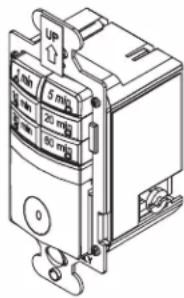
The RT-50 is a time switch that turns OFF the connected light or fan when the selected time expires. The light behind the ON/OFF button illuminates while the switch is OFF. One of the time button indicators is always lit to indicate the last used timer.
Manual ON
Turn ON the connected light or fan by pressing the desired time button, or the ON/OFF button. If you press the ON/OFF button, it activates the timer that was last used.
Manual OFF
While a timer is active, you can press the ON/OFF button to turn OFF the connected light or fan without delay.
Changing the selected time
If you decide that you need more or less time than you originally selected, restart the time switch by pressing the button that matches the amount of time you think you'll need.
SPECIFICATIONS
Voltage 120VAC, 60HZ
Load (Single Pole Circuit)
Incandescent or fluorescent lamp ....0 – 600 Watt
Fan Motor....1/6HP
Time Delay 1, 5, 10, 20, 30, 60 minutes
Environment....Indoor use only
Operating Temperature .....32° to 131°F (0° to 55°C)
Humidity 95% RH, non-condensing
Tools Needed
Insulated Screwdriver
Wire Strippers
INSTALLATION
1. Prepare the switch box.
After the power is turned OFF at the circuit breaker box, remove the the old switch out from the wall box.
2. Identify the type of circuit.
In a Single Pole Circuit (see Fig. 1), two single wires connect to two screws on the existing switch. A ground wire may also be present and connected to a ground terminal on the old switch. A neutral wire should also be present in the wall box.
NOTE: If a proper ground is not available, consult with a qualified electrician before continuing installation.
Only connect the RT-50 to a Single Pole Circuit. The RT-50 is not suitable for 3-way switching. If the existing wiring does not match the description for a Single Pole Circuit, you should consult with a qualified electrician.
3. Prepare the Wires.
Tag the wires currently connected to the existing switch, so that they can be identified later. Disconnect the wires. Make sure the insulation is stripped off the wires to expose their copper cores to the length indicated by the "Strip Gage," in Fig. 2 (approximately 1/2 inch).
4. Wire the time switch.
Twist the existing wires together with the wire leads on the time switch as indicated in the drawing. Cap them securely using the wire nuts provided. See Fig 3 on the next page.
- Connect the green or non-insulated (copper) GROUND wire from the circuit to the GROUND terminal on the RT-50.
- Connect the power wire from the circuit (HOT) to the black wire on the RT-50.
- Connect the power wire to the lamp or fan (LOAD) to the red wire on the RT-50.
-
Connect the NEUTRAL wires from the circuit to the white wire on the RT-50.
-
Put the RT-50 in the wall box with the time selection buttons positioned above the ON/OFF button.
Secure it to the wall box with the screws provided.
6. Install cover plates.
Install industry standard decorator wall switch cover plate (not included).

WARNING: TURN THE POWER OFF AT THE CIRCUIT BREAKER BEFORE WIRING.

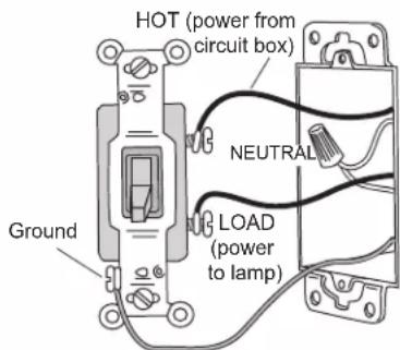
Fig. 1: Typical Single Pole Switch Wiring
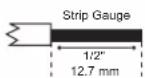
Fig. 2: Wire Stripping

WARNING: CONNECTING A PROPER
GROUND TO THE TIME SWITCH PROVIDES
PROTECTION AGAINST ELECTRICAL SHOCK
IN THE EVENT OF CERTAIN FAULT CONDITIONS.
7. Restore power to the circuit.
Turn on the breaker or replace the fuse.
Twist the existing wires together with the wire leads on the time switch as indicated in the drawing. Cap them securely using the wire nuts provided. See Fig 3.
- Connect the green or non-insulated (copper) GROUND wire from the circuit to the GROUND terminal on the RT-50.
- Connect the power wire from the circuit (HOT) to the black wire on the RT-50.
- Connect the power wire to the lamp or fan (LOAD) to the red wire on the RT-50.
- Connect the NEUTRAL wires from the circuit to the white wire on the RT-50.
8. Put the RT-50 in the wall box with the time selection buttons positioned above the ON/OFF button.
Secure it to the wall box with the screws provided.
9. Install cover plates.
Install industry standard decorator wall switch cover plate (not included).
10. Restore power to the circuit.
Turn on the breaker or replace the fuse.
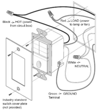
Fig. 3: Switch orientation, wire connections, and wall box assembly
TROUBLESHOOTING
To test the time switch:
The light behind the ON/OFF button should be ON when the switch is OFF. The indicator light on one of the time selection buttons is ON.
Press the ON/OFF button. The connected light or fan comes ON. The connected light or fan should turn OFF in the number of minutes indicated by the time selection indicator light. You can turn it OFF sooner by pressing the ON/OFF button again.
Light or fan will not turn ON (lighted switch is ON):
Press ON/OFF button. The connected light or fan should turn ON. If not:
- Check the light bulb and/or motor switch on the fan mechanism.
- Turn OFF power to the circuit, then check wire connections.
Light or fan will not turn ON (lighted switch is OFF and no indicator is ON):
- Shade the switch from external light to make sure that none of the indicator lights are ON.
- Check the light bulb and/or motor switch on the fan mechanism.
- Make certain that the circuit breaker is ON and functioning.
- Turn OFF power to the circuit then check wire connections.
• Call 1.888.817.0571 for technical support.
Light or fan will not turn OFF:
- Press the ON/OFF button.
- If connected light or fan does not turn OFF, turn OFF power to the circuit then check wire connections.
COVER PLATES
Wattstopper RT wall switches fit behind industry standard decorator style switch cover plates.
WARRANTY INFORMATION
Wattstopper warranties its products to be free of defects in materials and workmanship for a period of five (5) years. There are no obligations or liabilities on the part of Wattstopper for consequential damages arising out of, or in connection with, the use or performance of this product or other indirect damages with respect to loss of property, revenue or profit, or cost of removal, installation or reinstallation.