Soundweb 9010 - Audio Equipment BSS Audio - Free user manual and instructions
Find the device manual for free Soundweb 9010 BSS Audio in PDF.

User questions about Soundweb 9010 BSS Audio
0 question about this device. Answer the ones you know or ask your own.
Ask a new question about this device
Download the instructions for your Audio Equipment in PDF format for free! Find your manual Soundweb 9010 - BSS Audio and take your electronic device back in hand. On this page are published all the documents necessary for the use of your device. Soundweb 9010 by BSS Audio.
USER MANUAL Soundweb 9010 BSS Audio
Soundweb® 30040610 Installation Guide

natural_image
Vertical arrangement of gray geometric shapes including sun, snowflake, moon, snowflake, and diamond (no text or symbols)\*\*\*◆□□□★□○□□
v1.0 PW/JMK 21st March 1999
An example of this equipment has been tested and found to comply with the following European and international Standards for Electromagnetic Compatibility (only when used with a metal wallbox).
Radiated Emissions (EU): EN55022 (1990) Associated Equip.
Immunity (EU): EN50082/1 (1992) RF Immunity, Fast
Transients ESD
Radiated Emissions (USA): FCC part 15 Class A

☆○□□▼▼▲▼▼▼■□□○▼□■△□※※※■※□□□D
It should not be necessary to remove any protective earth or signal cable shield connections to prevent ground loops. Any such disconnections are outside the recommended practice of BSS Audio, and will render the EMC certificate void.
We have written this guide with the aim of helping installers and sound engineers alike to get the most out of the 9010. We recommend that you read this manual, particularly the section on installation, before attempting to operate the unit.
We welcome any comments or questions regarding the 9010 or other BSS products, and you may contact us at the address or World Wide Web site given in the warranty section.
The 9010 is designed to fit into a standard 3-gang US wallbox. Screws are provided to fix the unit in place. An optional bezel is available to 'dress' the edges of the panel if required.
Dimensions of the unit are shown below. BSS recommend the use of a metal wall box to ensure that the installation meets necessary EMC standards. If you require suitable
wallboxes, contact your distributor for part Z-010-BOX.

text_image
Wanboxes, contact your distributor for part Z-010-BOX. 63 mm (2.48 ins) 40 mm (1.57 ins) 116 mm (4.57 ins) 153 mm (6.02 ins) S###wabW##tart
◆□□■▼□○■☆☆+♣★◆■\*▼□■▲
Activity (yellow)
Irregular Flashing - This LED indicates data transfer
Sync (green)
Steady - This indicates the presence of one or more valid network connections.
Flashing - There is a problem with the incoming network signal - possibly the maximum cable length has been exceeded.
Master (yellow)
Flashing - The network is initialising. If it continues to flash for more than a few seconds, there is a cabling fault - either a double ring error or a problem with one of the cable connectors.
Steady - This unit has become the clock master for the network.
Off - This unit is clienting to the master's clock.
★□D※□
The 9010 requires 24v DC to be supplied externally. There are two ways of getting power into the unit:
- Connect a 24v DC power supply to the Power/Mic/Logic screw terminal block. Up to three more 9010's may be powered via network cabling from the Net Out of the 9010 which has the power supply connected (depending on cable length). Refer to diagrams on page 7 for more details.
- If it is inconvenient to cable a DC feed into the wallbox for the 9010, power may be applied via the network cable (on the Net In side), by using the Soundweb 9011 Power Interface to inject 24v DC from the power supply. Up to three more 9010's may be powered via network cabling from the Net Out of the 9010 which has the power supply connected (depending on cable length).
To assist calculating the maximum cable lengths between 9010s, refer to the spreadsheet 9010pwr.xls, which may be found in the soundweb designer installation, or on our website.
◆□□■▼ □✿■✿○✿✿▼✿○▲
Display Contrast button Display Contrast button
This is used to optimise the contrast of the display. Press and hold the contrast button to adjust. If you go past the optimum setting, keep holding the button so that adjustment starts from the beginning again.
Backlit graphics displayBacklit graphics display
The details displayed are specified by the Soundweb Designer software.

text_image
1 2 3 4 5 6 Soundwell™ (500) (Aumina Coa) 晶Six push buttons Six push buttons
As with the rotary control, the operation of these are determined by the Soundweb Designer software.
MicrophoneMicrophone
The built-in microphone may be used for paging etc. The routing of the signal from the microphone is determined by the Soundweb Designer software.
Rotary control Rotary control
Used to adjust parameter values. The function of this control is determined entirely by the Soundweb Designer software.
\* \* \* \* □ □ \* ■ \* \* \* \* ▼ \* \* ▲
Network In/Out*Network In/Out*
Network In - connects to the Network Out socket on another unit. Connecting multiple units is done in the same way - In to Out.
Refer to the 9088 installation guide and Soundweb Designer help for further details.
The connecting cable is CAT. 5 network cable, terminated with RJ45 connectors, with all 8 cores wired straight through.
Note that the twisted pairs in any CAT.5 network cable must be wired to the following pin pairs at each terminal:
1 (White-Orange) with 2 (Orange); 3 (White-Green) with 6 (Green);
4 (Blue) with 5 (White-Blue); 7 (White-Brown) with 8 (Brown)
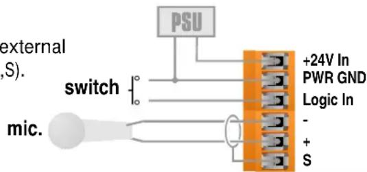
Power/Mic/Logic screw terminal block*Power/Mic/Logic screw terminal block*
Power In
DC power input (+24V and Gnd). See Power section.
Logic In
Used to connect a switch, (eg: a push-to-talk switch) to the 9010. This input is internally 'pulled up' to +5V DC via a 4.7kOhm resistor, so no external voltage source is needed. A common (ground) connection is provided. A switch may be connected between the input and common, as shown below.
Mic-,+,S
Three connections for an external dynamic microphone (-,+,S).
text_image
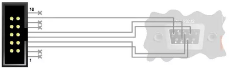
external (S). switch mic. PSU +24V In PWR GND Logic In - + SSerial Port*Serial Port*
Aux RS232
This is for connection to a PC if required.
The 10-pin header is arranged so that a
standard IDC ribbon cable will pin-out to an IDC D connector for standard PC RS232 connection.
text_image
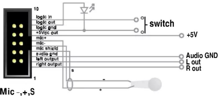
10 1 RS232Expansion Port*Expansion Port*
Left/Right/Audio Gnd output
An unbalanced line-level feed for use in custom applications for monitoring etc. Note that the outputs are polarity inverted so that external inverting amplifiers may be used. The signal on these outputs is determined by the Soundweb Designer software.
text_image
10 logic in logic out logic gnd +5Vdc out mic+ mic- mic shield audio gnd left output right output 1 Mic -,+,S switch +5V Audio GND L out R out s +Commoned to the Mic In terminals on the Power/Mic/Logic screw terminal block.
+5Vdc Out
A low current regulated +5V output for supplying power to electronics for custom applications. No more than 100mA may be drawn. Current drawn from this output will impact the length of network cable that may be used between the power supply and the 9010.
Logic in
Commoned to the Logic In terminal on the Power/Mic/Logic screw terminal block.
Logic Out
Used to connect the 9010 to a 'tally' indicator LED etc. The logic output produces 0V or +5V DC via an internal 440 Ohm resistor. A common ground connection is provided. An LED connected between the output (Anode, A) and ground (Cathode, K) will illuminate when the logic output is activated, without requiring any external current limiting resistor.
Connecting to a power supply
If using the 9010 unit without a 9011 power interface, the network and 9010 should be connected in the following fashion:
*refer to label on back of unit for connection positions.

flowchart
graph LR
    A["+24V PSU"] --> B["9010 unit"]
    B --> C["other units"]
    B -->|input| D["from network"]
    B -->|output| E["Output"]
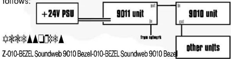
When using the 9010 unit with a 9011 power interface, connect as follows:
flowchart
graph LR
    A["+24V PSU"] --> B["9011 unit"]
    B --> C["9010 unit"]
    C --> D["other units"]
    B -->|out| C
    B -->|in| E["free network"]
    style A fill:#f9f,stroke:#333
    style B fill:#ccf,stroke:#333
    style C fill:#cfc,stroke:#333
    style D fill:#fcc,stroke:#333
Z-010-BEZEL Soundweb 9010 Bezel-010-BEZEL Soundweb 9010 Bezel
A sculptured plastic surround for the panel of the 9010 to 'dress' the panel edges for more elegant presentation.
Z-999-PSU Soundweb Power supply kit-999-PSU Soundweb Power supply kit
A 24Vdc universal input power supply suitable for powering up to four 9010's. This is a free-standing unit with integral IEC power inlet.
Z-010-BOX Soundweb 9010 wallbox-010-BOX Soundweb 9010 wallbox
A standard U.S. 3-gang outlet wallbox suitable for housing the 9010 in an installation.
Z-SW9011 Soundweb Power Inter
Allows DC power from a power supply to be injected into the network cable feeding the 9010(s).
\* \* \* \* ■ \* \* Ⓞ ▲ \* \* \* \* \* ▼ \* □ ■ ▲
External Microphone Input External Microphone Input
Frequency response (+-1dB) 20Hz to 20KHz
THD 0.05% (20Hz to 20KHz, +10dBu output)
Dynamic range 80dB typ. (22Hz to 22KHz unweighted)
Gain control range 34 to 72dB
Maximum input level -20dBu
Input impedance 2k Ohm
Equivalent Input Noise -106dBu @150 Ohm
Audio Outputs Audio Outputs
Frequency response (+-1dB) 20Hz to 20KHz
THD <0.05% (20Hz to 20KHz, 0dBu output)
Dynamic range 88dB typ. (22Hz to 22KHz
unweighted)
Maximum output level +4dBu
Output impedance 220 Ohm
Note - polarity is inverted to allow external headphone amplifier or line driver to be inverting.
Control Ports Control Ports
Logic output voltage 0 or +5V unloaded
Logic output impedance 440 Ohm
Control input impedance 4.7kOhms to +5V
GeneralGeneral
Maximum network cable length 300m/1000ft
Power consumption <5VA
(<200mA at 24V DC)