
LTV-W3 - Anemometer LA CROSSE TECHNOLOGY - Free user manual and instructions
Find the device manual for free LTV-W3 LA CROSSE TECHNOLOGY in PDF.


| Product Type | Anemometer |
| Brand | La Crosse Technology |
| Model | LTV-W3 |
| Dimensions | 5.5 x 2.0 x 2.0 inches |
| Weight | 0.25 lbs |
| Power Source | 1 x CR2032 battery (included) |
| Wind Speed Range | 0 to 112 mph (0 to 180 km/h) |
| Accuracy | ± 2 mph (3 km/h) |
| Units | mph, km/h, m/s, knots, Beaufort |
| Display Type | Backlit LCD |
| Transmission Range | 330 feet (100 meters) open air |
| Battery Life | Approximately 12 months |
| Operating Temperature | -40°F to 140°F (-40°C to 60°C) |
| Material | Weather-resistant plastic |
| Mounting | Pole or flat surface mount |
| Warranty | 1 year limited |
| Main Features | Wireless transmission, wind speed and direction, temperature, humidity |
| Maintenance | Clean with soft cloth, avoid harsh chemicals |
| Repairability | Battery compartment accessible; for other repairs contact support |
Frequently Asked Questions - LTV-W3 LA CROSSE TECHNOLOGY
User questions about LTV-W3 LA CROSSE TECHNOLOGY
0 question about this device. Answer the ones you know or ask your own.
Ask a new question about this device
Download the instructions for your Anemometer in PDF format for free! Find your manual LTV-W3 - LA CROSSE TECHNOLOGY and take your electronic device back in hand. On this page are published all the documents necessary for the use of your device. LTV-W3 by LA CROSSE TECHNOLOGY.
USER MANUAL LTV-W3 LA CROSSE TECHNOLOGY

Easy-to-Install
Mounting Bracket
LTV-W3
Initial Setup Install the Wind Cups if needed
Follow the instructions below to attach the Wind Cups with a mini screwdriver.

- Remove the Glide Sensor, and Wind Cups, from the package. Take note of the flat edges located on the head of the sensor and underside of the Wind Cups.

- Carefully tighten the screw on the side of the cups using a mini screwdriver. The screw should tighten into the flat edge of the post.

- Align the flat edges and place the Wind Cups on top of the sensor.
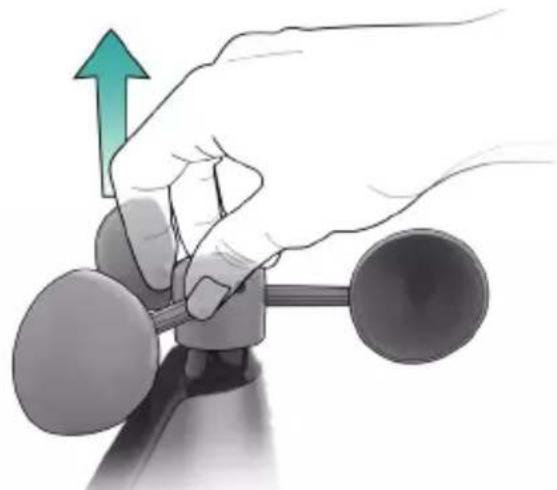
- When the screw is tight, gently pull up on the cups to ensure they are secure. If they pull off, start again with step two.
Power Up
Insert 3-AA batteries into the Glide Pro Sensor according to polarity.
- Press on and slide down the outer cover.
- Lift up and remove the battery cover.
- Insert batteries.
- Replace the battery cover and outer cover.

Adding Your Sensor to the La Crosse View App
- Open your La Crosse View app. On the Main Menu, scroll to ADD/EDIT and select DEVICES.
- On the Devices page, select the ADD DEVICE or PLUS (+) button.
- Scan the Barcode on your Sensor or type in the Device ID manually.
- Confirm the sensor image and Device ID and add a Device Name and Location Name. Select DONE.


Sensor Placement & Mounting

For Accurate Glide Pro Sensor Measurements
- Ideally, the sensor should be mounted on the tallest object in your area. Avoid positioning it parallel or below eaves, rooflines, trees, or other objects that may obstruct wind readings.
• Make sure all the screws on the Mounting Bracket, Wind Cups, and Battery compartment are securely fastened. - The sensor should be mounted with the Wind Cups on top.
- To optimize battery life, ensure the Solar Panel is facing the sun. The Solar Panel alone will not operate the sensor, batteries are required.
- For more information visit: bit.ly/wind_sensor_mounting
- The maximum wireless transmission range to the station is up to 400ft (121m) in open air. This does not include walls, floors, or other large obstructions.
See page 02 for wind cup installation information.
Basic Installation
Fence posts, poles, decks, and mailboxes are common mounting options due to their convenience. Many users prefer these types of locations as the data they provide is accurate from their ground level. However, because the wind in these spots is often affected by obstructions, the readings may differ when compared to local reporting stations.

- Mount the Mast to a flat surface with the four provided screws.

Place the Sensor on top of the Mast. Ensure the Solar Panel is facing the sun.

- Secure the Sensor to the Mast by tightening the screws on the side.
Flexible Installation


Hand Screw

Remove the Small Insert from the bracket and install the Hand Screw in its place. Then secure the sensor to the Mast by tightening the screws on the side (step 3 above).
This configuration allows you to attach the sensor to angled locations and easily make adjustments to ensure the Mast and Sensor are level.
Specifications
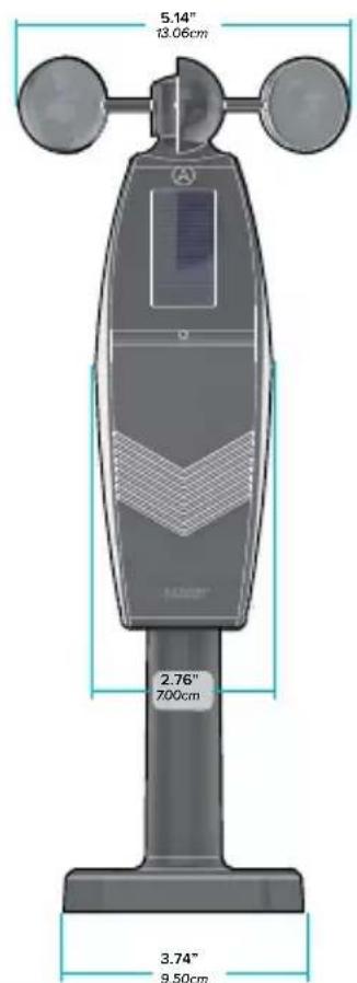
Glide Pro Wind Speed Sensor (LTV-W3)
• Wind Speed Range: 0 to 111 MPH (0 to 178 KMH)
• Transmission Range: Over 400 feet (121 meters) in open air RF 915MHz
- Update Interval: About every 31 seconds
• Power:
3-AA, IEC, LR6 batteries (not included)
• Battery Life: Over 36 months

Stay in Touch!
Ask questions, watch setup videos, and provide feedback on our social media outlets. Follow La Crosse Technology on YouTube, Twitter, Facebook and Instagram.



We're Here to Help
If you require additional assistance, get in touch with our friendly customer support team based in La Crosse, WI.
Online: bit.ly/contact_techsupport
Phone: 1.844.200.8752
Our knowledgeable customer support team is available:
Mon-Fri 8am-6pm CST
Warranty & Patents
La Crosse Technology, Ltd. provides a 1-year limited time warranty (from date of purchase) on this product relating to manufacturing defects in materials & workmanship.
La Crosse Technology, Ltd, 2830 S. 26th St., La Crosse, WI 54601
For Full Warranty Details, Visit:
www.lacrossetechnology.com/pages/warranty
Patents: www.lacrossetechnology.com/pages/patents
CA WARNING:
This product can expose you to chemicals including acrylonitrile, butadiene, and styrene, which are known to the State of California to cause cancer and birth defects or other reproductive harm. For more information, go to:
www.P65Warnings.gov
Designed in La Crosse, Wisconsin • Made in China • Printed in China • DC 071823
Battery Replacement
Battery Replacement Instructions
When batteries of different brand or type are used together, or new and old batteries are used together, some batteries may be over-discharged due to a difference of voltage or capacity. This can result in venting, leakage, and rupture and may cause personal injury.
• Always purchase the correct size and grade of battery most suitable for the intended u
- Always replace the whole set of batteries at one time, taking care not to mix old and new ones, or batteries of different types.
- Clean the battery contacts and also those of the device prior to battery installation.
- Ensure the batteries are installed correctly with regard to polarity (+ and -).
- Remove batteries from product during periods of non-use. Battery leakage can cause corrosion and damage to this product.
- Remove used batteries promptly.
- For recycling and disposal of batteries, and to protect the environment, please check the internet or your local phone directory for local recycling centers and/or follow local government regulations.
FCC Statement
This equipment has been tested and found to comply with the limits for a Class B digital device, pursuant to part 15 of the FCC Rules. These limits are designed to provide reasonable protection against harmful interference in a residential installation.
This equipment generates, uses and can radiate radio frequency energy and, if not installed and used in accordance with the instructions, may cause harmful interference to radio communications. However, there is no guarantee that interference will not occur in a particular installation. If this equipment does cause harmful interference to radio or television reception, which can be determined by turning the equipment off and on, the user is encouraged to try to correct the interference by one or more of the following measures:
- Reorient or relocate the receiving antenna.
- Connect the equipment into an outlet on a circuit different from that to which the receiver is connected.
FCC Radiation Exposure Statement
This device complies with FCC radiation exposure limits set forth for an uncontrolled environment and it also complies with Part 15 of the FCC RF Rules. This equipment must be installed and operated in accordance with provided instructions and the antenna(s) used for this transmitter must be installed to provide a separation distance of at least 20 cm from all persons and must not be co-located or operating in conjunction with any other antenna or transmitter. End-users and installers must be provided with antenna installation instructions and consider removing the no-collocation statement.
- Increase the separation between the equipment and receiver.
- Consult the dealer or an experienced radio/TV technician for help.
This device complies with Part 15 of the FCC Rules.
Operation is subject to the following two conditions:
(1) This device may not cause harmful interference, and
(2) This device must accept any interference received, including interference that may cause undesired operation.
Caution: Any changes or modifications not expressly approved by the party responsible for compliance could void the user's authority to operate the equipment.


- Initial setup install the wind cups if needed
- Power up
- Adding your sensor to the la crosse view app
- Vocowers
- Buy cars
- Airports
- Sensor placement & mounting
- For accurate glide pro sensor measurements
- Basic installation
- Specifications
- Glide pro wind speed sensor (LTV-W3)
- Stay in touch
- We're here to help
- Warranty & patents
- Ca warning
- Battery replacement
- Battery replacement instructions
- Fcc statement
- Fcc radiation exposure statement
- This device complies with part 15 of the fcc rules
- Operation is subject to the following two conditions
Brand : LA CROSSE TECHNOLOGY
Model : LTV-W3
Category : Anemometer