SA200-001 - Thermostat PECO - Free user manual and instructions
Find the device manual for free SA200-001 PECO in PDF.

| Product Type | Thermostat |
| Brand | PECO |
| Model | SA200-001 |
| Dimensions (approx.) | 4.5 x 4.5 x 1.2 inches (114 x 114 x 30 mm) |
| Weight (approx.) | 0.3 lbs (150 g) |
| Power Source | 2 AA batteries (3V DC) |
| Display Type | LCD digital display |
| Temperature Range | 5°C to 35°C (41°F to 95°F) |
| Temperature Accuracy | ±0.5°C |
| Control Type | Manual on/off and temperature adjustment |
| Mounting | Wall-mounted (screws included) |
| Compatibility | Most heating and cooling systems (24VAC) |
| Programming | Not programmable (basic manual operation) |
| Battery Life | Approximately 1 year |
| Low Battery Indicator | Yes (display icon) |
| Maintenance | Clean with a soft dry cloth; avoid liquids |
| Safety Features | Overheat protection (auto shut-off) |
| Spare Parts | Batteries (AA) only |
| Repairability | Not user-serviceable; replace device if faulty |
| Certifications | CE, RoHS |
| Warranty | 1 year limited |
| Package Contents | Thermostat, mounting screws, user manual |
Frequently Asked Questions - SA200-001 PECO
User questions about SA200-001 PECO
0 question about this device. Answer the ones you know or ask your own.
Ask a new question about this device
Download the instructions for your Thermostat in PDF format for free! Find your manual SA200-001 - PECO and take your electronic device back in hand. On this page are published all the documents necessary for the use of your device. SA200-001 by PECO.
USER MANUAL SA200-001 PECO
Installation Instructions
GENERAL
The SA200-001 is a ceiling mount 360° occupancy sensor designed for automatic HVAC system control. This sensor provides a changeover (form C) output for fan coil controller to activate/deactivate the operation of fan coil automatically.
DESCRIPTION
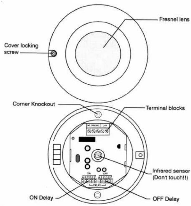
text_image
Fresnel lens Cover locking screw Corner Knockout Terminal blocks ON Delay OFF Delay Infrared sensor (Don't touch!! NELOW NC 24W ON OFF ON OFF ON OFFINSTALLATION & WALK TEST
Installation
- Open the cover by loosening the screw. Bend the clip and remove the PCB module.
- Route the cable into the unit base and mount the base on the ceiling.
- Replace the PCB module. Connect the cable to the corresponding terminals according to the following instructions.
Wiring Diagram
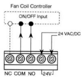
text_image
Fan Coil Controller ON/OFF Input 24 VAC/DC NC COM NO -24V◆ NC-COM-NO: Output for ON-OFF control of fan coil operation.
◆ 24 V: Power supply (non-polarity)
- Replace the front cover and perform the walk test.
Walk Test
Apply power, allowing 25 seconds for sensor to warm up. The LED will blink (long and short) during warm up period. Ensure the jumper head connectors of ON & OFF delays are placed at "A" position (shortest delay). After the warm up expires, walk across the (invisible) detection zones at normal pace. The LED will light whenever sensor detects the motion. Note: The LED will blink if any jumper connector is not properly placed.
OPERATION
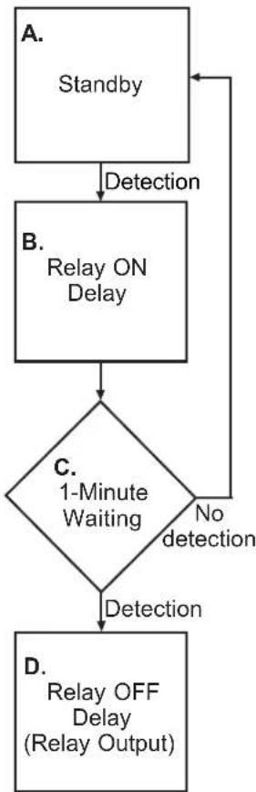
Operation Diagram
A. Standby
After warm up period expires, the sensor enters into standby mode. Sensor will check if delay jumpers are properly placed. If not, the LED will flash.
B. Relay ON Delay
Relay ON delay is the time given to sensor to verify true occupancy before activating the relay output. Any further detection during ON delay will NOT reset the timer.
C. 1-minute Waiting
When Relay ON delay expires, the sensor enters into a 1-minute waiting time. If no detection within 1 minute, then sensor will return to standby mode. If any detection occurs, then relay output will be activated and Relay OFF delay will be started.
A. Relay OFF Delay
Relay OFF delay is the time of relay activating. Every detection during this period will reset the timer.
flowchart
graph TD
    A["Standby"] -->|Detection| B["Relay ON Delay"]
    B --> C{1-Minute Waiting}
    C -->|No detection| D["D. Relay OFF Delay (Relay Output)"]
    C -->|Yes detection| E["A."]
ON / OFF DELAY
The ON and OFF delays are designed to provide intelligent energy management of HVAC system. ON delay is the time given to the sensor to certify the occupancy, before it activates the fan controller. OFF delay is the time that relay is active. Both ON and OFF delays can be easily set by placing the jumper on the corresponding pins as follows:
natural_image
Symmetrical geometric pattern composed of radial segments in grayscale shades (no text or symbols)Top View 360°
Side View
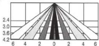
radar
| Value | |---| | 2.4 | | 3.0 | | 3.6 | | 4.2 || Mount height | 2.4m | 3.0m | 3.6m | 4.2m |
| Coverage(Dia.) | 6.0m | 7.5m | 9.0m | 10.5m |
SPECIFICATIONS
Infrared sensor .... Dual element
Power supply 24 ± 2 V AC/DC
Detection range.... Height x 2.5 at 25°C
Output format.... Form C, 30 VDC, 0.2A max.
Current drain 5 mA @24 VAC
Mounting height 2.4\~4.2 m
Detectable speed .... 0.1\~3.0 m/sec.
RFI immunity ...... Av. 20 V/m (10\~1,000 MHz)
Temperature ....-20°C\~38°C (-4°F \~ 100°F)
Humidity 95% RH max.
Dimensions 110 (Dia.) x 44 (H) mm

WARNING
- READ THESE INSTRUCTIONS CAREFULLY BEFORE ATTEMPTING TO INSTALL, OPERATE OR SERVICE THIS DEVICE.
- Failure to observe safety information and comply with instructions could result in PERSONAL INJURY, DEATH AND/OR PROPERTY DAMAGE.
- To avoid electrical shock or damage to equipment, disconnect power before installing or servicing.
•To avoid potential fire and/ or explosion do not use in potentially flammable or explosive atmospheres. - Retain these instructions for future reference. This product, when installed, will be part of an engineered system whose specifications and performance characteristics are not designed or controlled by PECO, Inc. You must review your application and national and local codes to assure that your installation will be functional and safe.
CAUTION

Use Copper wire only, insulate or wire nut all un-used leads.

© Copyright 2004 PECO, Inc. All Rights Reserved P/N 68736 3220-1385 Rev1 Page 2