SB200-001 - Thermostat PECO - Free user manual and instructions
Find the device manual for free SB200-001 PECO in PDF.

| Product Type | Thermostat |
| Brand | PECO |
| Model | SB200-001 |
| Dimensions | 12 x 8 x 2 cm |
| Weight | 150 g |
| Power Supply | 2 x AA alkaline batteries |
| Display Type | LCD screen with backlight |
| Temperature Range | 5°C to 35°C |
| Programmability | 7-day programmable with 4 time periods per day |
| Compatibility | Standard 24V HVAC systems (gas, oil, electric) |
| Installation | Wall mount, requires wiring to HVAC system |
| Connectivity | None (standalone) |
| Warranty | 1 year limited warranty |
| Maintenance | Wipe with a soft dry cloth; do not use liquids |
| Safety | Low battery indicator; over-temperature protection |
| Spare Parts | Batteries (AA); mounting screws |
| Repairability | User replaceable batteries; professional repair for internal faults |
| Additional Features | Frost protection mode; filter reminder; keypad lock |
Frequently Asked Questions - SB200-001 PECO
User questions about SB200-001 PECO
0 question about this device. Answer the ones you know or ask your own.
Ask a new question about this device
Download the instructions for your Thermostat in PDF format for free! Find your manual SB200-001 - PECO and take your electronic device back in hand. On this page are published all the documents necessary for the use of your device. SB200-001 by PECO.
USER MANUAL SB200-001 PECO
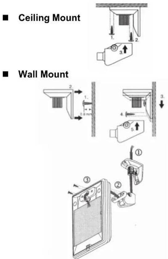
Installation Instructions
GENERAL
The SB200-001 is an occupancy sensor designed for automatic HVAC system control. This sensor provides a changeover (form C) relay signal output for fan coil controller to activate/deactivate the operation of fan coil automatically. This sensor can be wall or corner mounted with 110°, 50 ft (15m) detection range.
INSTALLATION HINTS
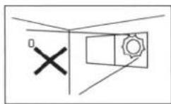
Do not install where unit is exposed to direct sunlight or directly above strong sources of heat.
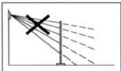
Make sure the detection area does not have any obstruction (plants, large pieces of furniture, curtains etc.) which may block the detection.
DESCRIPTION
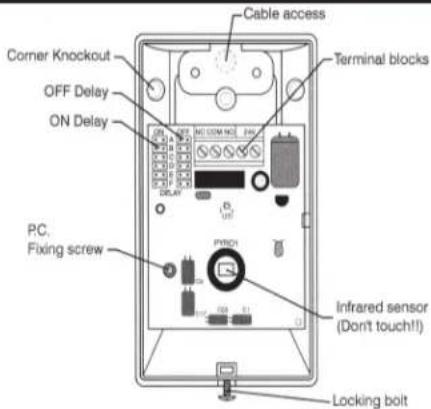
text_image
Cable access Corner Knockout OFF Delay ON Delay Terminal blocks PC. Fixing screw Infrared sensor (Don't touch!! Locking boltINSTALLATION & WALK TEST
Installation
- Mount the base of mounting bracket on the selected position. Route the cable through the access tunnel of mounting bracket.
- Open the front cover by loosening the locking screw at the bottom. Route the cable into the unit and assemble the mounting bracket with the unit.
- Connect the cable to the corresponding terminals according to the following instructions.
Wiring Diagram
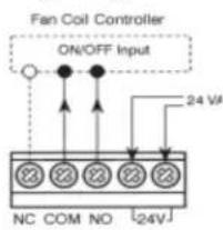
text_image
Fan Coil Controller ON/OFF Input 24 VA NC COM NO [24V]◆ NC-COM-NO: Output for ON-OFF control of fan coil operation. Dry contact signal.
◆ 24 V: Power supply (non-polarity)
- Replace the front cover and then perform the walk test.
Walk Test
Apply the power supply to the sensor and wait for about 45 seconds to warm unit up. The LED will blink (long-short) during warm up period. Ensure the jumper head connectors of ON and OFF delays are placed on "A" position (shortest delay). Walk across the detection zones (invisible) at normal speed. The LED will light whenever the sensor detects the motion. Note: If any jumper is not properly placed, the LED will blink.
OPERATION
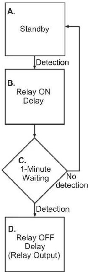
Operation Diagram
A. Standby
After warm up period expires, the sensor enters into standby mode. Sensor will check if delay jumpers are properly placed. If not, the LED will flash.
B. Relay ON Delay
Relay ON delay is the time given to sensor to verify true occupancy before activating the relay output. Any further detection during ON delay will NOT reset the timer.
C. 1-minute Waiting
When Relay ON delay expires, the sensor enters into a 1-minute waiting time. If no detection within 1 minute, then sensor will return to standby mode. If any detection occurs, then relay output will be activated and Relay OFF delay will be started.
D. Relay OFF Delay
Relay OFF delay is the time of relay activating. Every detection during this period will reset the timer.
flowchart
graph TD
    A["Standby"] -->|Detection| B["Relay ON Delay"]
    B --> C{1-Minute Waiting}
    C -->|No detection| D["D. Relay OFF Delay (Relay Output)"]
    C -->|Yes detection| E["A. Standby"]
RANGE ADJUSTMENT
In order to suit different rooms or areas, the detection range of SB200-001 can be adjusted by changing the direction of the sensor. To change the sensor direction, release the screw on the mounting bracket and then carefully move the sensor to the direction desired.
ON / OFF DELAY
The ON and OFF delays are designed to provide intelligent energy management of the HVAC system. ON delay is the time given to the sensor to certify the occupancy, before it activates the fan controller. OFF delay is the time that relay is active. Both ON and OFF delays can be easily set by placing the jumper on the corresponding pins as follows:
pie
| Side view | Value | |---|---| | Top Section | 110° | | Bottom Section | 2.4m | | Bottom Section (Bottom) | 2.5m | | Bottom Section (Bottom) | 8m | | Bottom Section (Bottom) | 15m |SPECIFICATIONS
Power supply.....24 ± 2 V AC/DC
Detection range.....110°, 15 x 15 m at 25°C
Output format.....Form C, 30 VDC, 0.2A max.
Current drain....Standby: 5 mA Active: 18 mA
Mounting height.....1.8\~3.6 m
Mounting bracket.....MB-99
Detectable speed....0.1\~3.0 m/sec.
RFI immunity......Av. 20 V/m (10\~1,000 MHz)
Temperature....-20°C\~38°C (-4°F \~ 100°F)
Humidity....95% RH max.
Dimensions....112 x 66 x 45 mm

WARNING
- READ THESE INSTRUCTIONS CAREFULLY BEFORE ATTEMPTING TO INSTALL, OPERATE OR SERVICE THIS DEVICE.
- Failure to observe safety information and comply with instructions could result in PERSONAL INJURY, DEATH AND/OR PROPERTY DAMAGE.
- To avoid electrical shock or damage to equipment, disconnect power before installing or servicing.
- To avoid potential fire and/or explosion do not use in potentially flammable or explosive atmospheres.
- Retain these instructions for future reference. This product, when installed, will be part of an engineered system whose specifications and performance characteristics are not designed or controlled by PECO, Inc. You must review your application and national and local codes to assure that your installation will be functional and safe.
CAUTION

Use Copper wire only, insulate or wire nut all un-used leads.
CE
© Copyright 2004 PECO, Inc. All Rights Reserved P/N 68737 3220-1387 Rev1 Page 2