
JEGN12L015808 - Kettle Jocel - Free user manual and instructions
Find the device manual for free JEGN12L015808 Jocel in PDF.


| Product Type | Gas Water Heater |
| Brand | Jocel |
| Model | JEGN12L015808 |
| Power Supply | 220V AC, 50Hz |
| Electrical Power | 33W |
| Gas Type | 2H-G20-20mbar |
| Gas Category | I2H @20 mbar |
| Nominal Heat Input (Hi) | 24 kW |
| Nominal Heat Output | 21 kW |
| Minimum Heat Input | 8 kW |
| Max Flow Rate (25°C rise) | 12 kg/min |
| Max Water Pressure | 10 bar |
| Min Water Pressure | 0.2 bar |
| Temperature Range | 35°C to 65°C |
| Ignition Method | Water Control Automatic Pulse Ignition |
| Flue Duct Diameter | 60 mm |
| Pipe Connections | Gas Inlet G1/2, Cold Water Inlet G1/2, Hot Water Outlet G1/2 |
| Control Type | Touch digital display |
| Safety Features | Self-check, flame-out, over-heat, power-cut, fan breakdown, over load, leakage, over wind pressure, over temperature, timing protection |
| Appliance Type | B23, B53 |
| Degree of Electrical Protection | IPX2 |
| Energy Efficiency Class | A |
| Working Modes | Auto, Eco, Normal |
| Package Contents | Gas water heater, gas inlet connector (with seal ring), expansion screws, mounting screws, self-tapping screws, user manual |
Frequently Asked Questions - JEGN12L015808 Jocel
User questions about JEGN12L015808 Jocel
0 question about this device. Answer the ones you know or ask your own.
Ask a new question about this device
Download the instructions for your Kettle in PDF format for free! Find your manual JEGN12L015808 - Jocel and take your electronic device back in hand. On this page are published all the documents necessary for the use of your device. JEGN12L015808 by Jocel.
USER MANUAL JEGN12L015808 Jocel
MANUAL DE INSTRUÇÕES
natural_image
Technical line drawing of a device casing with internal components and dimension标注 (no text or symbols)

natural_image
Illustration of a hand holding a spray bottle with a pipe, emitting vapor and smoke (no text or symbols)Fig. 5
natural_image
Technical line drawing of a mechanical device with two heating elements and a base, no text or symbols present.Fig. 6
Thank you for purchasing our gas water heater.
Read this Manual before installing and operating and keep for future reference.
Special advice
Read the technical instructions before installing the appliance.
Read the user's instructions before lighting the appliance.
The manufacturer or any danger resulted from installation and operations not bear responsibility for any danger resulted from installation and operations not in accordance to this manual.
When the outdoors temperature is less than 0^ C, the residual water inside the heater must be drained after use.
EN:26: 2015
FEATURES & BENEFITS
■ Micro-Computer Intelligent Control System
The core component of the gas water heater is micro-computer intelligent control system, which is one of today's most advanced mechatronic technology. The CPU chipset can analyze automatically and set the optimal working parameter rapidly according to different data such as the flowing water quantity, the pressure situation and the actual inlet water temperature.
■ Digital Control for Automatic Constant Temperature of Outlet Water
This function is to monitor the outlet water temperature by a temperature sensor and to transfer the information to the micro-computer, so that the micro-computer could adjust the gas and air supply quantity to guarantee the constant outlet water temperature according to the temperature set by the user and the actual inlet water temperature automatically.
■ Low Start-Up Water Pressure
The lowest start-up water pressure of this product could reach 0.02MPa (the minimum water rate is 2.5L/min), so it could also be used in the residence area with low water pressure.
■ AI Artificial Intelligent Memory Function
The gas water heater could work with the temperature you set last time when you restart it, so that you do not need to set the temperature again, which is great experience of the idea of ergonomics.
■ Effective and Energy-Saving
This product has advanced technologies called Strengthened Combustion and Forced Combustion. These patents aim to make the best use of heat energy with high working efficiency.
■ Set Temperature by Touch
You could set the required temperature easily by touching the digital display. The setting temperature is from 35^ C to 65^ C, which can meet different water temperature requirements with easy operation.
■ Multiple Safety Protection
This product has safety protections includes self-check protection, flame-out protection, over-heat protection, accidental power-cut protection, fan breakdown protection, over electric load protection, electric leakage protection, over wind pressure protection, over temperature protection, timing protection etc.
TIPS
The above conclusion comes from the safety protection test under lab experimental conditions. It may be affected by the surroundings in actual using environment. Thus, please use the product in proper conditions rather than using it devastatingly.

Fig. 1
(The dimension information is for reference only. Please refer to the actual product.)

Fig. 2(Unit: mm)
(The dimension information is for reference only. Please refer to the actual product.)
INSTALLATION
Advice for the installer
WARNING
INSTALLATION, FIRST IGNITION AND MAINTENANCE WORK MUST BE PERFORMED BY QUALIFIED PERSONNEL ONLY, IN ACCORDANCE WITH THE INSTRUCTIONS PROVIDED.
INCORRECT INSTALLATION MAY HARD INDIVIDUALS, ANIMALS OR PROPERTY; THE MANUFACTURER WILL NOT BE HELD RESPONSIBLE FOR ANY DAMAGE CAUSED AS A RESULT.
- This appliance is designed to produce hot water for domestic use.
- It should be connected to a distribution network for domestic hot water that must be compatible with its performance and power levels.
- The use of the appliance for purposes other than those specified is strictly forbidden. The manufacturer cannot be held responsible for any damage caused by improper, incorrect and unreasonable use of the appliance or by the failure to comply with the instructions given in this manual.
- Installation, maintenance and all other interventions must be carried out in full conformity with the governing legal regulations and the instructions provided by the manufacturer. Incorrect installation can harm persons, animals and possessions; the manufacturing company shall not be held responsible for any damage caused as a result.
- The appliance is delivered in a cardboard box. Once you have removed all the packaging, make sure the appliance is intact and that no parts are missing. If this is not the case, please contact your supplier.
- Keep all packaging material (clips, plastic bags, polystyrene foam, etc.) out of reach of children as it may present a potential hazard.
- In the event of a fault and/or malfunction, turn the appliance off, turn off the gas cock and do not attempt to repair it yourself. Contact a qualified professional instead. Before any maintenance or repair work is performed on the appliance, make sure you have disconnected it from the electricity supply by switching the external bipolar switch to the "OFF" position and removing the fuse.
-
All repairs, which should only be performed using original spare parts, should be carried out by a qualified professional. Failure to comply with the above instructions could compromise the safety of the appliance and invalidate all liability on the part of the manufacturer.
-
In the event of any maintenance or other structural work in the immediate vicinity of the ducts or flue gas exhaust devices and their accessories, switch the appliance off by switching the external bipolar switch to the "OFF" position and shutting off the gas control valve. When the work has been completed, ask a qualified technician to check the efficiency of the ducting and the devices.
- Turn the appliance off and turn the external switch "OFF" to clean the exterior parts of the appliance. Clean using a cloth dampened with soapy water. Do not use aggressive detergents, insecticides or toxic products.
SAFETY REGULATIONS
• Install the appliance on a solid wall which is not subject to vibration.
Noisiness during operation.
- When drilling holes in the wall for installation purposes, take care not to damage any electrical wiring or existing piping.
Electrocution caused by contact with live wires. Explosions, fires or asphyxiation caused by gas leaking from damaged piping.
Damage to existing installations.
Flooding caused by water leaking from damaged piping.
- Perform all electrical connections using wires which have a suitable section. Fire caused by overheating due to electrical current passing through undersized cables.
- Protect all connection pipes and wires in order to prevent them from being damaged.
Electrocution caused by contact with live wires. Explosions, fires or asphyxiation caused by gas leaking from damaged piping.
Flooding caused by water leaking from damaged piping.
- Make sure the installation site and any systems to which the appliance must be connected comply with the applicable norms in force.
Electrocution caused by contact with live wires which have been installed incorrectly. Damage to the appliance caused by improper operating conditions.
- Use suitable manual tools and equipment (make sure in particular that the tool is not worn out and that its handle is fixed properly); use them correctly and make sure they do not fall from a height. Replace them once you have finished using them.
Personal injury from the falling splinters or fragments, inhalation of dust, shocks, cuts, pricks and abrasions.
Damage to the appliance or surrounding objects caused by falling splinters, knocks and incisions.
- Make sure any portable ladders are positioned securely, that they are suitably strong and that the steps are intact and not slippery and do not wobble when someone climbs them.
Ensure someone provides supervision at all times.
Personal injury caused by falling from a height or cuts (stepladders shutting accidentally).
- Make sure any rolling ladders are positioned securely, that they are suitably strong, that the steps are intact and not slippery and that the ladders are fitted with handrails on either side of the ladder and parapets on the landing.
Personal injury caused by falling from a height.
- Make sure the workplace has suitable hygiene and sanitary conditions in terms of lighting, ventilation and solidity of the structures.
Personal injury caused by knocks, stumbling etc.
- Protect the appliance and all areas in the vicinity of the work place using suitable material.
Damage to the appliance or surrounding objects caused by falling splinters, knocks and incisions.
- Handle the appliance with suitable protection and with care.
Damage to the appliance or surrounding objects from shocks, knocks, incisions and squashing.
- During all work procedures, wear individual protective clothing and equipment.
Personal injury caused by electrocution, falling splinters or fragments, inhalation of dust, shocks, cuts, puncture wounds, abrasions, noise and vibration.
- Place all debris and equipment in such a way as to make movement easy and safe, avoiding the formation of any piles which could yield or collapse.
Damage to the appliance or surrounding objects from shocks, knocks, incisions and squashing.
- All operations inside the appliance must be performed with the necessary caution in order to avoid abrupt contact with sharp parts.
Personal injury caused by cuts, puncture wounds and abrasions.
- Reset all the safety and control functions affected by any work performed on the appliance and make sure they operate correctly before restarting the appliance.
Explosions, fires or asphyxiation caused by gas leaks or an incorrect flue gas exhaust.
Damage or shutdown of the appliance caused by out-of-control operation.
- Before handling, empty all components that may contain hot water, carrying out any bleeding if necessary.
Personal injury caused by burns.
- Descale the components, in accordance with the instructions provided on the safety data sheet of the product used, airing the room, wearing protective clothing, avoid mixing different products, and protect the appliance and surrounding objects.
Personal injury caused by acidic substances coming into contact with skin or eyes; inhaling or swallowing harmful chemical agents.
Damage to the appliance or surrounding objects due to corrosion caused by acidic substances.
- If you detect a smell of burning or smoke, keep clear of the appliance, disconnect it from the electricity supply, open all windows and contact the technician.
Personal injury caused by burns, smoke inhalation, asphyxiation.

Fig. 3
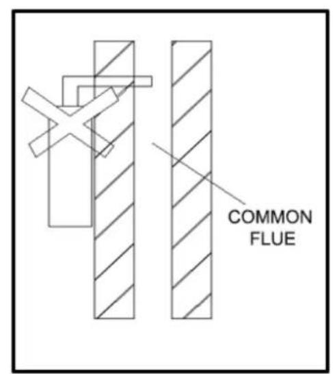
Fig. 4

natural_image
Cartoon illustration of a hand holding a bottle and a bag with a smiling face, next to a pipe with a spray bottle (no text or symbols)Fig. 5

natural_image
Technical line drawing of a mechanical device with two heating elements and a base, no text or symbols presentFig. 6
INSTALLATION REQUIREMENTS
- The flue of the gas water heater should be installed through an external wall, the heater cannot be installed in outdoors. (Fig.3)
The gas water heater installed in a suitably ventilated room, in accordance with the regulations in force. It is not allowed to install in the bedroom, underground, bathroom or any other places with poor ventilation. (For B23, B53type)


- The flue of the heater cannot be connected
to a common flue (Fig. 4).
- Please don't install the heater in places where special chemicals are used, such as the laundries or factories etc., otherwise it may cause rusting, shorten the lifetime of the heater, or prevent normal working. (Fig. 5)
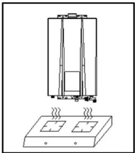
- Don't install the heater above the gas stoves or other heat sources. (Fig. 6)
- The gas water heater should be kept away from the combustible materials with the distance shown in Fig. 7 at least.
- When the installation parts' materials are combustible or flammable should be used frame-proof board to isolate, heat-resistant plate and wall gap should be greater than 10mm, and the size of heat plate should be larger than water heater shell for 10mm. (Fig. 8)
Fig 7
Fig 8
- The electric wires and electric equipment are not allowed to be placed on the top of the gas water heater. The horizontal distance between the gas water heater and other electric equipment should be more than 400mm.
- The power socket must have a reliable ground wire to improve safety. In order to reduce the number of times of plugging, it is better to use a socket with a switch. Whenever the water heater finishes working, please switch it off to avoid being electrified in a long term. The power supply socket should not be installed in the moist environment.
- The socket should be installed at the side of the product, and never be installed below


natural_image
Technical line drawing of a device enclosure with internal components and wiring (no text or symbols)
natural_image
Technical line drawing of a cabinet or enclosure with internal components and mounting base (no text or symbols)the machine or the place with splashes, near the heat source, in exposure to sun and rain, or the place where it is not easy to control.
- The installation place of socket must be far away from the spraying space, so as to avoid spraying the socket during shower.
■ Installation Method
1. Installation of Gas Water Heater
Drill holes in the wall according to Fig.9, put an expansion bolt into the upper hole and plastic gasket into the lower hole, mount the water heater vertically on the upper bolt without inclination and tighten the lower holes with expansion bolts.
Fig. 9 (Unid.: mm)
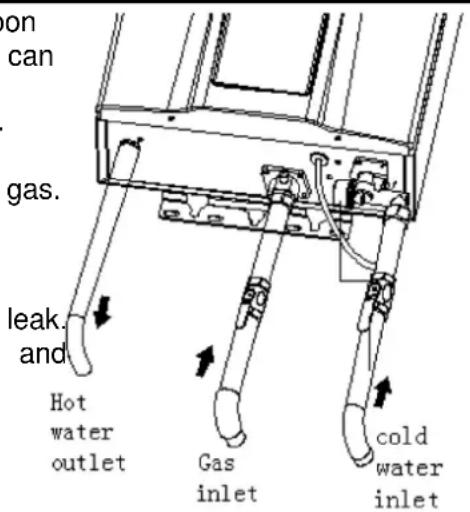
2. Installation of water and gas pipes (Fig. 10)
- It can be used when the flue system can ensure that the provided gas pressure can reach the lowest requirement. If gas water heater reaches the rated heat input, the gas pressure must reach the rated heat input in the technologic parameter form.
Fig. 10
Gas inlet
- Before connecting the gas supply, check the rating plate on the right side of the right front cover to be sure that the heater is rated for the same gas to which it will be connected.
- All such pipe shall be either new or previously used for no other purpose than conveying gas; and must be in good condition and free from internal obstructions. Burred ends shall be reamed to the full bore of the pipe. All fittings used shall be of malleable iron, yellow brass, or approved plastic fittings. And flexible tube is not allowed.
- When your connections are made, check for gas leaks at all joints (this includes all existing piping). Apply soapy water to all gas fittings and gas valve. Soap bubbles are a sign of a leak.
NOTE: No substance
other than air, carbon dioxide or nitrogen can be introduced into the gas piping.
NOTE: If
leak, shut off the gas.
After leak,
fittings to stop leak. Turn the gas on and
check soapy
Never leaks
match or flame.
you have a
verifying the tighten appropriate
again with a solution.
test for gas using a
Cold
water inlet
- When facing the heater, the cold-water inlet is on your right and the hot water outlet is on your left. Although water piping throughout your structure may be other than copper, we recommend that copper piping be used for at least 0.92 m before and after the heater (follow local codes). Keep water inlet pipe to no less than 1/2" diameter to allow the full flow capacity.
- Remember that water pressure must be sufficient to activate the heater when drawing hot water from the top floor. If the hot and cold connections to the heater are reversed, the heater will not function. 1/2"Copper or brass fittings work best when connected to the connectors. The flexible type connectors will make instillation easier and seals to the water valve by means of a union connection with a washer type gasket at the joint. No pipe dope or thread tape is to be used at this joint. Be certain there are no loose particles or dirt in the piping. (Fig. 10)
- Water pressure must be sufficient to activate the water heater, the maximum pressure for the appliance is 10bar, even with the effects of water dilation, the water pressure in the appliance shall not exceed this value.
■ Hot water outlet
Use a flexible or rigid pipe to connect with the sprayer without valve. If a valve or switch is connected to the sprayer, the outlet pipe shall not use heat and pressure unendurable material such as plastics, aluminum pipes, so as to avoid the pipe from breaking and scalding the user.
3. Installation of the flue:
■ Flue Duct Installation of Forced-Exhausted Gas Water Heater (B23, B53 type)
This product is forced exhaust type gas water heater; it can be used only after the flue duct is installed according to the requirements strictly and can exhaust the waste gas to the outdoor area. It's not allowed to use the gas water heater without installing the flue duct correctly. Please follow the below requirements during the installation of flue duct.
- Refer to Fig.11 about the installation method. If the flue duct is too short, you can extend it aptly. Check the flue duct and see if there is any damage or leakage every half a year.
- The length of the flue duct should be less than 8m,
- The horizontal distance of the flue duct is the shorter the better. The flue duct end should have a 2^ downward inclination (Fig. 11), so as to let the condensing water flows out.
- The distance between the flue duct and the combustible materials should be more than 150mm. If the flue duct needs to get through the combustible materials or wall, it should use the heat shield material to pack the flue duct with the thickness over20mm. (Refer to Fig.8)
- No cement between the flue duct and wall for the convenience of maintenance.
- The flue duct should be fixed tightly. The connection part could use self-adhesive foil to avoid the waste gas going back into the room.
Fig. 11

■ Cautions for flue installation
- Other flues with different specifications are strictly prohibited. Do not change the specification of the flue.
- The installation of the flue must be correct, otherwise the waste gases will flow back and be dangerous. (Fig. 12)
Fig. 12
| Wrong installation | Problem Caused | Correct installation |
| Exhaust gas leak in to room | ||
| Abnormal Combustion | outdoors | |
| Work Abnormally | outdoors |
WARNING
Installation, first ignition and maintenance work must be performed by qualified personnel only, in accordance with the instructions provided. Incorrect installation may harm individuals, animals or property; the manufacturer will not be held responsible for any damage caused as a result.
USING METHODS
- This appliance is designed to produce hot water for domestic use.
- It should be connected to a distribution network for domestic hot water that must be compatible with its performance and power levels.
- The use of the appliance for purposes other than those specified is strictly forbidden. The manufacturer cannot be held responsible for any damage caused by improper, incorrect and unreasonable use of the appliance or by the failure to comply with the instructions given in this manual.
- Installation, maintenance and all other interventions must be carried out in full conformity with the governing legal regulations and the instructions provided by the manufacturer.
- Incorrect installation can harm persons, animals and possessions; the manufacturing company shall not be held responsible for any damage caused as a result.
- In the event of a fault and/or malfunction, turn the appliance off, turn off the gas cock and do not attempt to repair it yourself. Contact a qualified professional instead.
- Before any maintenance or repair work is performed on the appliance, make sure you have disconnected it from the electricity supply by switching the external bipolar switch to the "OFF" position and removing the fuse.
- All repairs, which should only be performed using original spare parts, should be carried out by a qualified professional.
- Failure to comply with the above instructions could compromise the safety of the appliance and invalidate all liability on the part of the manufacturer.
- In the event of any maintenance or other structural work in the immediate vicinity of the ducts or flue gas exhaust devices and their accessories, switch the appliance off by switching the external bipolar switch to the "OFF" position and shutting off the gas control valve.
- When the work has been completed, ask a qualified technician to check the efficiency of the ducting and the devices.
- If the appliance should be out of use for a prolonged period, it is recommended that the electrical power supply be disconnected and that the external gas cock be closed. If low temperatures are expected, the appliance and system pipe work should be drained in order to prevent frost damage.
- When permanently deactivating the appliance, make sure that the operations are carried out by qualified technical professional.
- Turn the appliance off and turn the external switch "OFF" to clean the exterior parts of the appliance. No flammable items should be left or used in the vicinity of the appliance.
■ Safety regulations
- Do not perform operations which involve opening the appliance.
Electrocution from live components.
Personal injury caused by burns due to overheated components, or wounds caused by sharp edges or protrusions.
- Do not perform operations which involve removing the appliance from its installation space.
Electrocution from live components.
Flooding caused by water leaking from disconnected piping.
Explosions, fires or intoxication caused by gas leaking from disconnected piping.
- Do not damage the power supply cable.
Electrocution from live uninsulated wires.
- Do not leave anything on top of the appliance.
Personal injury caused by an object falling off the appliance as a result of vibrations. Damage to the appliance or items underneath it caused by the object falling off as a result of vibrations.
- Do not climb onto the appliance.
Personal injury caused by the appliance falling.
Damage to the appliance or any objects underneath it caused by the appliance falling away from its installation space.
- Do not climb onto chairs, stools, ladders or unstable supports to clean the appliance.
Personal injury caused by falling from a height or cuts (stepladders shutting accidentally).
- Do not attempt to clean the appliance without first switching it off and turning the external switch to the off position.
Electrocution from live components.
- Do not use insecticides, solvents or aggressive detergents to clean the appliance.
- Damage to plastic and painted parts.
Do not use the appliance for any use other than normal domestic use.
Damage to the appliance caused by operation overload.
Damage caused to objects treated inappropriately.
- Do not allow children or inexperienced individuals to operate the appliance.
Damage to the appliance caused by improper use.
- If you detect a smell of burning or smoke coming from the appliance, disconnect it from the electricity supply, turn off the main gas valve, open all windows and call for assistance.
Personal injury caused by burns, smoke inhalation, intoxication.
- If there is a strong smell of gas, turn off the main gas valve, open all windows and call for assistance.
Explosions, fires or intoxication
This appliance can be used by children aged from 8 years and above and person with reduced physical, sensory or mental capabilities or lack of experience and knowledge if they have been given supervision or instruction concerning use of the appliance in a safe way and understand the hazards involved. Children shall not play with the appliance.
Cleaning and user maintenance shall not be made by children without supervision.

flowchart
graph TD
    A["1"] --> B["2"]
    C["9"] --> D["8"]
    E["3"] --> F["4"]
    G["7"] --> H["6"]
    I["5"] --> J["5"]
    K["4"] --> L["m³/h L/min"]
    M["Auto Eco"] --> N["Gas flow Water flow"]
    O["Fire Icon"] --> P["Fire Icon"]
    Q["Wind Icon"] --> R["Wind Icon"]
    S["Water Icon"] --> T["Water Icon"]
1. Flame feedback indicates
When the water heater is working, the flame signal feedback dynamic display.
2. Inlet water flow instruction
When the inlet water flow is detected, LED Display will light up.
3. Functional area of the main digital display
• Water heater at normal working mode, show the setting temperature.
- When the water heater faults, show the fault code.
4. Information area
• Real-time water flow production indicates
• Real-time gas consumption production indicates
- Inquiry accumulative amount of using water
• Inquiry accumulative amount of gas consumption
5. Water flow production, gas flow production unit
6. Child lock function
When the child lock protection on, lighting the pattern. When setting the temperature reaches 48^ C or more, press the increase key, the icon flashes to indicate that child lock function protection.
7. Adjust temperature statement indicates
At temperature adjustment mode, flashing display, always lighting at non-adjustment state.
8. Working mode indicates
Show the current water heater working mode.
9. Fan indicates
Dynamic display when fan operation.
TOUCH BUTTON INSTRUCTIONS

flowchart
graph TD
    A["@ button"] --> B["Press this key to select the system working mode or query function."]
    B --> C["ON/OFF button"]
    C --> D["Up and down button\nFor temperature or water flow selector settings."]
    D --> E["Water heater running for startup and shutdown."]
PREPARATION BEFORE IGNITION
- Make sure that the gas used is in accordance with the gas stipulated in the label.
- Insert the plug, and then switch on the power. The buzzer sounds "bi"
- Turn on the gas valve.
TEMPERATURE SETTING
Press the “○”(on/off) key on the control panel, the screen display and the designed hot water temperature. Press Up “↖” or Down “↖” to set the hot water temperature as desired.
The lowest hot water temperature of this product is 35^ C, highest is 65^ C. To set the water temperature from 35 to 48^ C press the + button repeatedly. Pressing and releasing will trigger a rise of 1^ C. From 48 to 65^ C see the table.
| Temperature | Settings | Settings mode |
| 35-48°C | 1°C | Push button | √ |
| 48-50°C | 2°C | Push button for 5 sec | |
| 50-55°C | 5°C | Push button | √ |
| 55-60°C | 5°C | Switch OFF the machine and then push button for 5 sec | √ |
| 60-65°C | 5°C | Push button | √ |

ATTENTION!
WATER AT A TEMPERATURE OVER 50°C CAUSES SERIOUS BURNS. ALWAYS CHECK THE WATER TEMPERATURE BEFORE USE.
IGNITION & WATER OUTLET
- Open the water valve, there will be spraying signal shown on the screen. When the fan whirls, the igniter turns on and flame shows, hot water will come out accordingly. The display shows the setting temperature of outlet water.
- When using, water outlet flow and temperature can be adjusted in the same method as mentioned. After opening water and starting, Setting the range of 35-48°C, above 48°C, only press down key (Child lock function to prevent burns). If want to set the temperature higher than 48°C, turn off the hot water faucet and then press the button to warming.
- When the water valve is open, but the switch stays at OFF position, the water heater will stop working, and only cold water runs out. If hot water is needed, you should press ON button.
- Turn off the water valve and water heater stop working, but the fan still blows the combustion chamber for several seconds. The machine will show the temperature set last time when opening the water valve next time.
- Every time after using the gas water heater, the gas valve must be closed, and AC power must be cut.
Attention:
- If the water valve is open before the water heater is switched on, the gas water heater will into the protective mode, and the buzzer sounds. Please close the water valve then.
- It might take several trial ignitions after installation or the first use after recharging the gas tank to push out all the air remained in the gas pipe (G30).
- The temperature shown on the screen is the setting temperature, while the outlet water temperature differs according to the length of pipes and different seasons. Therefore, please refer to the actual outlet water temperature.
- If hot water flow excesses the water heater's capacity, the water may not be hot enough.
Please turn down the water flow accordingly - Every time the water heater starts working, please pay attention to the setting temperature on the display and be careful not to being scaled.
- In order to avoid being scaled, whenever using the water heater, you must test the water temperature with your hand before showing.
- When the gas water stops working and the display shows error codes, please close the water valve and reopen. Or press the on/off button until the machine is off, and
then restart it. If the water heater still cannot operate regularly, please turn off the gas valve and cut the power, recharge the machine and ignite again after a few minutes.
USE FUNCTION MODE
In standby mode (ie, no water status), press the function (@) key, you can select "Auto", "Eco", "normal" three modes in turns, they can cycle, the system default normal mode. Three types of function mode instruction:
- Normal mode(default): According to the user to set automatic temperature thermostat, then "Auto", "Eco" display lights are not bright.
- Auto mode: ("Auto" display lights is bright.) According to the inlet water temperature, the system automatically adjusts the setting temperature (as shown in Table1), allowing users to get the most comfortable hot water supply in anytime.
Table 1 - Temperature mappingtable
| N.° | Local Water Temperature | Corresponding Temperature |
| 1 | ≤ 15^ | 45^ |
| 2 | 16^ -21^ | 43^ |
| 3 | 22^ -27^ | 40^ |
| 4 | ≥ 28^ | 38^ |
Note: Under the Auto mode, after the heater switch-on, the temperature displayed is the one set before the heater starts to work. The temperature will not change according to the local water temperature change after the heater starts to work.
- Eco mode: ("Eco" display lights is bright.) In the state of saving mode, after calculation by microcomputer, automatically adjust the amount of gas supply, compared other modes more economical by water heater gas consumption, not only save gas, but also can guarantee a constant water temperature to meet the requirements of users.
In the state of saving mode, the user can freely select the desired of setting water temperature, the user presses the up or down keys to adjust the setting temperature does not exit the power saving mode, in this case the user needs in the standby mode press the function key again to exit the power-saving mode.
INSTANT HOT WATER PRODUCTION AND REAL-TIME AIR CONSUMPTION DISPLAY
When the water heater in working condition, the display will take turns showing the current real-time hot water production and real-time gas consumption, the figures will be changed accord the actual working conditions, so that users can understand the water heater current working conditions.
For example: When the real-time information display "12.0L / min", indicates that current real-time hot water production by water heater per minute 12L. When the real-time information display "2.0m³/h", indicates that current real-time gas consumption by water heater per hour 2.0m³
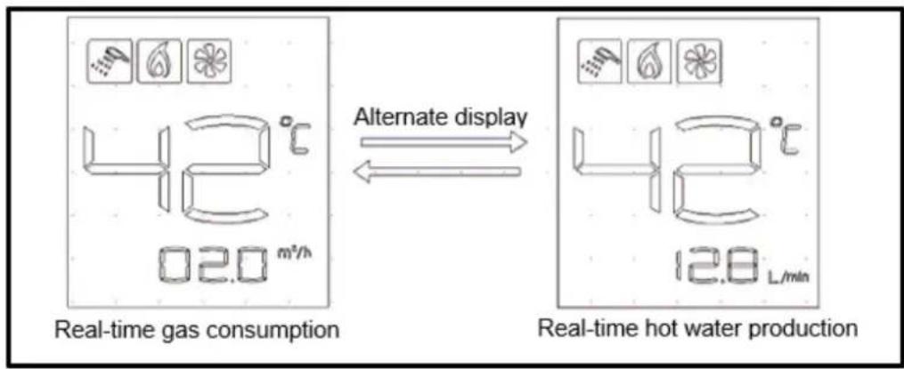
Fig.13
SAFETY CAUTIONS
■ Prevention of freezing water
- Drain the residual water inside the heater to prevent frizzing the water after every use when the environment temperature is near or under 0^ C, do as instructed (Fig. 14)
- Close down the gas valve ①
- Turn the water temperature knob ② to "low" position, or turn the water volume button knob to "large" position (level).
- Close down the cold-water valve sans③, if a valve is installed on the hot water circuit, open it.
- If there is a control valve④ at the hot water outlet, please open it.
- Turn the drain valve and take off, replace it after the residual water is completely discharged.
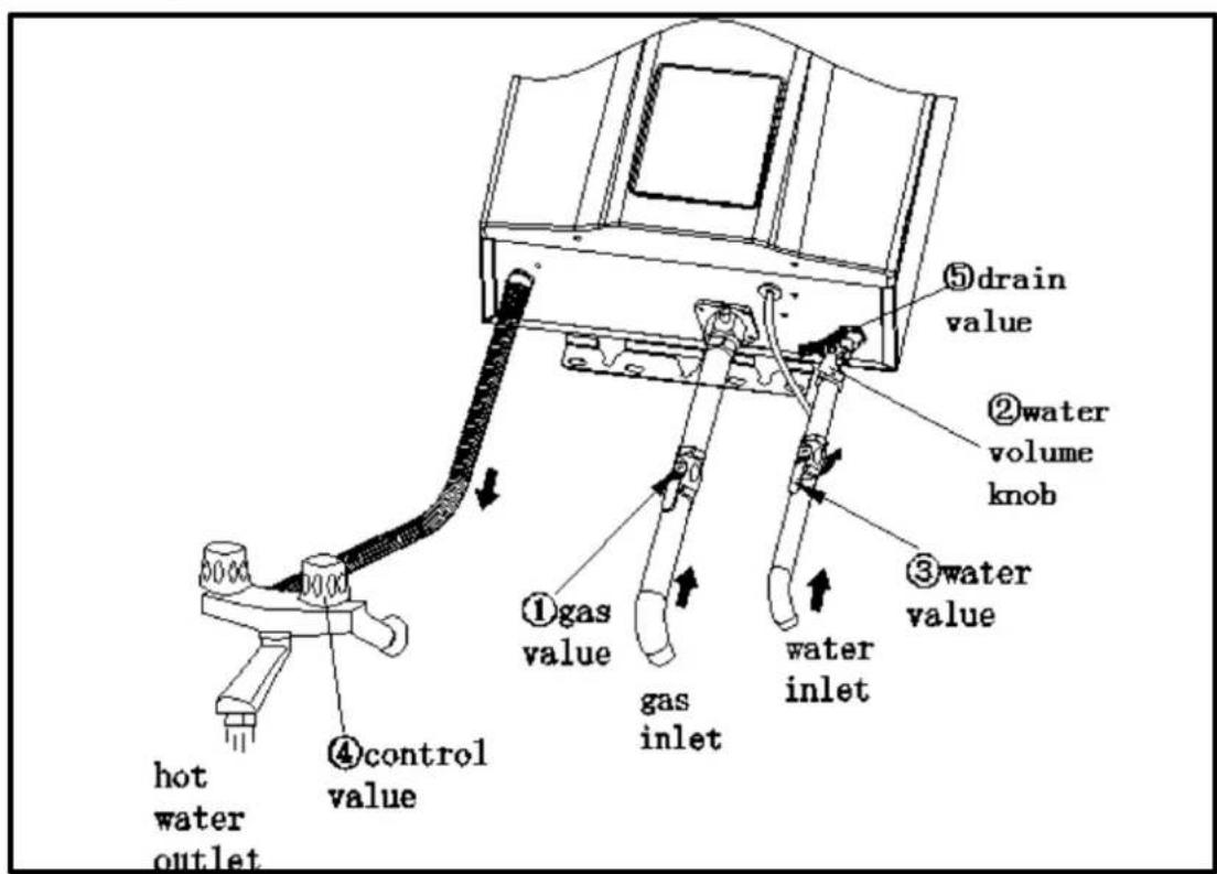
Fig. 14
■ Gas accident prevention
- Check if the flame of burner is out after use and do not forget to turn off the gas valve (Fig. 15) and power.
- Always check the gas connectors for gas leakage with soapsuds. If any gas leakage is detected, open the room windows and doors. At that moment, do not ignite or operate the switch of electric appliances or plugs because the flame or electric spark can result in explosive accidents. (Fig. 16)
- Heaters must use the gas type which the heater is designed to use, different type of gas or the same gas in different place must not be used.
- Always check the gas pipe and change the pipe every year to avoid gas leakage due to cracking.
- If the flame goes unsteadily, stop using the water heater and contact the qualified service facility for repair or adjustment.

Fig. 15
Fig. 16
■ Fire prevention
- Do not leave the water heater unattended whilst still in operation.
- In case of power failure or water failure, turn off the gas valve and water inlet valve.
- Do not place towels or clothes on top of the water heater. (Fig. 17)
- Do not store inflammables, explosives or volatiles near the water heater. (Fig. 18)
- Never incline the gas tank or turn it upside down, the fluid gas is easy to flow into the heater and cause fires (G30).
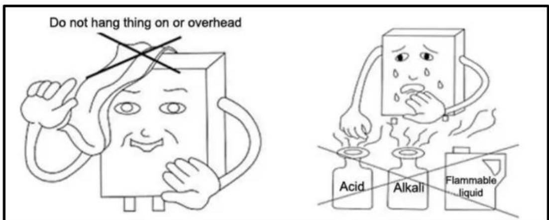
Fig. 17
Fig. 18
■ Carbon Monoxide toxicosis prevention
- This product must exhaust the waste gas to the outdoor area during working, so the flue duct must be connected to the joint on the top of the water heater to exhaust the waste gas out to the outdoor area, keep the air fresh indoor and avoid incomplete combustion. Otherwise, it will cause danger or even death.
- Too low or too high gas pressure leads to abnormal combustion. At that moment, stop using the water heater and get in contact with a service engineer.
- Dust and accelerated carbon would block the heat exchanger due to long time use, and affect the combustion performance, causing the Carbon monoxide to increase. Therefore, contact a qualified person to clean and clear the dust and accelerated carbon every half year to ensure the combustion product discharges smoothly.
- The heater must be installed vertically, if inclined it will make the flame touch the heat exchanger and cause the monoxide to increase.
- Don't drink the heater water
- The water in the heater is not suitable for drinking.
■ Handle with abnormal conditions
If there is abnormal burning (flame light-back, flame lift, yellow tip or black smoke, etc), smell or noise, or other emergent situations, keep calm and shut off the gas supply valve and power switch, and contact the service facility or gas dealers for repair or adjustment.
■ Scald prevention
- When using the heater discontinuously, be careful not to be scalded by the over high temperature hot water at the start and stop times.
- During use and immediately after, do not touch any places especially the surround of the flame
- Check window or the front cover except for the knob and control panel in order to avoid scalding.

WARNING:
Forbid any interference with a sealed component, a fire or explosion, may result causing property damage, personal injury or loss of life.
MAINTENANCE
- The appliances should be checked and maintained periodically by a competent person.
- Check the gas tube/pipe regularly for any defect. Contact service center for any doubt.
• Always check the gas pipe for cracks.
• Always check for leaking water. - Ask qualified technicians to examine the burner, flue and fan once a year.
- Always check the flame inside the water heater for any abnormal conditions.
- Keep the cover of the water heater clean.
- This product uses water pressure to open the channels. When the water pressure is lower than 0.2bar, the heater cannot be ignited.
- The drain valve is dripping. When the water pressure is too high, the drain valve will release the water to reduce the pressure and protect the heater.
- When the heater is supplying hot water to several points at the same time, the hot water flow would be reduced, or no hot water will issue at all.
- When the temperature outside is too low and the exhausted gas meets the cold air, it will be condensed as white fog. This is normal.
- When the water temperature is too high, set to a lower temperature and reduce the water tap. If the water temperature outlet is too high, please open the tap to reduce the temperature.
- When the water temperature is too low, and the hot water volume is so high so that it exceeds the heater's heating power, the outlet water will be not hot enough, please reduce the water volume.
- In order to ignite immediately, the fan in the appliance will delay running for a long time and then stop automatically. This is normal.
- When you use the multi-function shower, the resistance may be too large, and the water inlet pressure will be too low or the water inlet volume will be too little (below the starting –up water volume), there may be flameout or cannot be ignited, please choose the suitable shower function.
- The residual water in the heater may be frozen in the winter, this is bad for the heater, so you must drain the water after use. (Please refer to the drain methods.).
- In order not to create scaling, please close the gas valve after using the heater, let the hot water out of the appliance. When the outlet of the hot water is cold, close the cold-water valve.
CLEANING
The water heater should be cleaned annually, keep the dust away from flue gas passageway. Seethe Cleaning Instructions below. (Only for service engineer)
- Turn off power, shutoff gas supply;
- Wait one hour to cool down water heater;
- Remove the front cover, by taking out Cover Screw;
- Using compressed air or equivalent to clean the area between the fins and the heat exchanger;
- Do not unscrew or move any other parts of water heater;
- After Cleaning, put the front cover back.
| Causes | Errors | Heatexchangerassemblyblocked | Burner assemblyblocked | External wind pressuretoo high | Air supply not enough | Adjust watertemperature wrongly | Pressure of cold watertoo low | Main cold water valveoff | Supply gasinappropriate | High | There is air in the gaspipe | Main gas valve halfon | Main gas valve off | Flame out while using | |
| Low | ● | Flame out while using | |||||||||||||
| ● | ● | Non-ignition after opening thecold water valve | |||||||||||||
| ● | Deflagration after ignition | ||||||||||||||
| Yellow flame with smoke | |||||||||||||||
| Abnormal flame with strange smell | |||||||||||||||
| ● | Ignition with strange sounds | ||||||||||||||
| ● | ● | Water still not hot,when turning tothe high temperature position | |||||||||||||
| ● | Water too hot, when turning to thelow temperature position | ||||||||||||||
| Flame out when turning to the lowtemperature position | |||||||||||||||
| Flame not out when the coldwater valve is closed | |||||||||||||||
| ● | Solutions | ||||||||||||||
| ● | The same as mentionedabove | ||||||||||||||
| Rotate thewaterflowadjustmentrodaappropriately | Improve air exchange, andlet more fresh air inStop using it | ||||||||||||||
| Improve air exchange, andlet more fresh air inStop using it | Contact after TechnicalAssistance | ||||||||||||||
| The same as mentionedabove | The same as mentionedabove |
SPECIFICATIONS
| Name | GAS WATER HEATER | |
| Model | JEGN12L015808 | |
| Nominal Heat Input (Hi) | 24kW | |
| Nominal Heat Output | 21kW | |
| Minimum Heat Input | 8 kW | |
| Minimum Heat Input | 7,4 kW | |
| Max Flow Rate (rise 25°C) | 12kg/min | |
| Appliance Type | B23, B53 | |
| Gas Type | 2H-G20-20mbar Only | |
| Gas category | I2 H @20 mbar | |
| PIN number | 0063CR7772 | |
| Max Water pressure | Pw=10bar | |
| Min water pressure | Pw = 0,2bar | |
| Electrical power supply | 220VCA,50Hz | |
| Electric power | 33W | |
| Degree of electrical protection | IPX2 | |
| Ignition method | Water Control Automatic Pules Ignition | |
| Destination country | PT,ES | |
| Pipe joint | Gas Inlet | G 1 / 2 |
| Cold Water Inlet | G 1 / 2 | |
| Hot Water Outlet | G 1 / 2 | |
| Flue Duct Diameter | ∅ 60 | |
| Warning:Read the technical instructions before installing the appliance.Read the use's instructions before lighting the appliance. CE 0063/20 | ||
SPECIFICATIONS
| Name | GAS WATER HEATER | |
| Model | JEGB12L015815 | |
| Nominal Heat Input (Hi) | 24kW | |
| Nominal Heat Output | 21.4kW | |
| Minimum Heat Input | 8 kW | |
| Minimum Heat Input | 7,4 kW | |
| Max Flow Rate (rise 25°C) | 12kg/min | |
| Appliance Type | B23, B53 | |
| Gas Type | 3B/P-G30-29mbar Only | |
| Gas category | I3B/P-G30-29mbar | |
| PIN number | 0063CR7772 | |
| Max Water pressure | Pw=10bar | |
| Min water pressure | Pw = 0,2bar | |
| Electrical power supply | 220VCA,50Hz | |
| Electric power | 33W | |
| Degree of electrical protection | IPX2 | |
| Ignition method | Water Control Automatic Pules Ignition | |
| Destination country | PT,ES | |
| Pipe joint | Gas Inlet | G 1 / 2 |
| Cold Water Inlet | G 1 / 2 | |
| Hot Water Outlet | G 1 / 2 | |
| Flue Duct Diameter | ∅ 60 | |
| Warning:Read the technical instructions before installing the appliance.Read the use's instructions before lighting the appliance. CE 0063/20 | ||
ELECTRICAL DIAGRAM

※If change, No special advice!
PACKAGING AND ACCESSORIES
| Description | Quantity |
| Gas water heater | 1 |
| Connector of gas inlet (with rubber seal ring) | 1 |
| Expansion screws | 1 |
| Mounting screws | 2 |
| Usermanual | 1 |
| Self-tapping screws | 2 |
ErP DATA
| Model | JEGN12L015808JEGB12L015815 |
| Declare load profile | M |
| Water heating energy efficiency (η WH) | 78,0% |
| Water heating energy efficiency class | A |
| Daily gas consumption (Corrected Kwh) | 7,836 |
| Daily electrical consumption (Corrected Kwh) | 0,044 |
| Annual fuel consumption AFC (GJ) | 6 |
| Annual Electricity consumption AEC (KWh) | 10 |
| No (mg/kWh) | 47 |
| Indoor sound power level LWA (dB) | 61 |
GENERAL WARRANTY TERMS
- The warranty is valid only on presentation of invoice of purchase.
- This WARRANTY is limited exclusively to parts substitution ineffective due to faulty manufacture, made in our workshops.
- The elimination of several faults of the scope of the guarantee is made for repair or replacement of defective parts, according to the discretion of our technical services. Defective parts are our property.
- Are not covered under warranty damage caused by transportation, neglect or poor use, improper assembly or installation, as well as external influences such as: lightning strikes or power, flooding, humidity, etc.
- Lose warranty, all appliances that are not being used according to the instructions, or connected to FEEDING NETWORKS not guarantee a constant voltage of 220/240V.
- The warranty does not cover damages for personal injury or damage caused directly or indirectly in any capacity whatsoever.
- This warranty terminates when it is found to have been undergoing repairs, alterations or interventions by any person not authorized by Jocel.
THE WARRANTY EXPIRES
- If the appliance has not been installed by an Accredited Technician.
- Exceeded the period of 2 years for home appliances and 06 months for industrial appliances, warranty expires and assistance will be made by charging the costs of manpower, according to current fees.
- With the modification or disappearance of the nameplate of the appliance.
TECHNICAL ASSISTANCE
For technical assistance request, our services are available through the following contacts:
Telef. 00 351 252 910351
Fax: 00 351 252 910367
E-mail: assistencia@jocel.pt
http://www.jocel.pt
SEDE:
DECLARATION OF CONFORMITY
CE
We declare on our own responsibility that the machine indicated below:
Product GAS WATER HEATER
Brand JOCEL
Model JEGN12L015808
The CE mark guarantees that the appliance conforms to the following directives:
2016/426/EU
Relating to gas appliances
2014/30/EU
Relating to electromagnetic compatibility
2014/35/EU
Relating to electrical safety
2009/125/EC
Energy related Products
814/2013
EU Regulation
SEDE:
DECLARATION OF CONFORMITY
CE
We declare on our own responsibility that the machine indicated below:
Product GAS WATER HEATER
Brand JOCEL
Model JEGB12L015815
The CE mark guarantees that the appliance conforms to the following directives:
2016/426/EU
Relating to gas appliances
2014/30/EU
Relating to electromagnetic compatibility
2014/35/EU
Relating to electrical safety
2009/125/EC
Energy related Products
814/2013
EU Regulation
natural_image
Illustration of a hand holding a bag with a warning symbol, surrounded by other items including a bottle and a cross (no text or symbols present)Fig. 5

natural_image
Technical line drawing of a mechanical device with two heating elements and a base, no text or symbols present.Fig. 6
Telef. 00 351 252 910351
Fax: 00 351 252 910367
E-mail: assistencia@jocel.pt
http://www.jocel.pt
SEDE:
- Special advice
- FEATURES & BENEFITS
- ■ Micro-Computer Intelligent Control System
- ■ Digital Control for Automatic Constant Temperature of Outlet Water
- ■ Low Start-Up Water Pressure
- ■ AI Artificial Intelligent Memory Function
- ■ Effective and Energy-Saving
- ■ Set Temperature by Touch
- ■ Multiple Safety Protection
- TIPS
- INSTALLATION
- Advice for the installer
- WARNING
- SAFETY REGULATIONS
- INSTALLATION REQUIREMENTS
- ■ Installation Method
- Installation of Gas Water Heater
- Installation of water and gas pipes (Fig. 10)
- Gas inlet
- Cold
- ■ Hot water outlet
- Installation of the flue:
- ■ Cautions for flue installation
- USING METHODS
- ■ Safety regulations
- Flame feedback indicates
- Inlet water flow instruction
- Functional area of the main digital display
- Information area
- Water flow production, gas flow production unit
- Child lock function
- Adjust temperature statement indicates
- Working mode indicates
- Fan indicates
- TOUCH BUTTON INSTRUCTIONS
- PREPARATION BEFORE IGNITION
- TEMPERATURE SETTING
- ATTENTION!
- IGNITION & WATER OUTLET
- Attention:
- USE FUNCTION MODE
- INSTANT HOT WATER PRODUCTION AND REAL-TIME AIR CONSUMPTION DISPLAY
- SAFETY CAUTIONS
- ■ Prevention of freezing water
- ■ Gas accident prevention
- ■ Fire prevention
- ■ Carbon Monoxide toxicosis prevention
- ■ Handle with abnormal conditions
- ■ Scald prevention
- WARNING:
- MAINTENANCE
- CLEANING
- SPECIFICATIONS
- ELECTRICAL DIAGRAM
- PACKAGING AND ACCESSORIES
- ErP DATA
- GENERAL WARRANTY TERMS
- THE WARRANTY EXPIRES
- TECHNICAL ASSISTANCE
- DECLARATION OF CONFORMITY
- CE
Brand : Jocel
Model : JEGN12L015808
Category : Kettle