500216 - Receiver MuxLab - Free user manual and instructions
Find the device manual for free 500216 MuxLab in PDF.


| Product Type | Audio Zone Amplifier (Class-D) |
| Model | 500216 |
| Dimensions (W x D x H) | 4.80" x 3.43" x 1.58" (122 x 87 x 40 mm) |
| Weight | 2.16 lbs (0.98 kg) |
| Power Supply | 24 VDC, 2.5 A (external adapter, 110-240 VAC input) |
| Power Output (Default) | 2 x 20 W @ 4 ohms |
| Bridge Connection | 1 x 40 W @ 8 ohms |
| Audio Inputs | 2 x RCA (stereo), 1 x 3.5 mm stereo jack, 1 x balanced mic (3-pin terminal block) |
| Audio Outputs | 4-pin terminal block for speakers, 3.5 mm line output (cascade) |
| Microphone Features | 48V phantom power, dynamic mic, wireless mic; input modes: 48V, MIC, LINE |
| Control Methods | Front panel pushbuttons, IR remote (optional), RS232 |
| Special Functions | Dual-mono, noise gate, bridge mode, mic mixer, volume/bass/treble control |
| Frequency Response | 20 Hz – 20 kHz |
| Signal-to-Noise Ratio | 80 dB (at max output) |
| Total Harmonic Distortion + Noise | 1% @ 1 kHz (nominal level) |
| RS232 Communication | 9600 bps, 8 data bits, 1 stop bit, no parity |
| IR Remote Protocol | NEC format, user code 40FF |
| Cooling | Convection (no fan) |
| Enclosure Material | Metal (antistatic) |
| Compliance | FCC, CE, RoHS |
| Warranty | 2 years |
| Package Contents | Amplifier, 2 terminal blocks, RS232 cable, 24 VDC adapter, power cord, 4 plastic feet, user manual |
| Safety Precautions | Do not dismantle; keep away from moisture; unplug before cleaning; use in ventilated area |
Frequently Asked Questions - 500216 MuxLab
User questions about 500216 MuxLab
0 question about this device. Answer the ones you know or ask your own.
Ask a new question about this device
Download the instructions for your Receiver in PDF format for free! Find your manual 500216 - MuxLab and take your electronic device back in hand. On this page are published all the documents necessary for the use of your device. 500216 by MuxLab.
USER MANUAL 500216 MuxLab
Audio Zone Amplifier 2 x 20 watts
Installation Guide
500216


SAFETY PRECAUTIONS
To insure the best from the product, please read all instructions carefully before using the device. Save this manual for further reference.
- Follow basic safety precautions to reduce the risk of fire, electrical shock and injury to persons.
- Do not dismantle the housing or modify the module. It may result in electrical shock or burn.
- To prevent fire or shock hazard, do not expose the unit to rain, moisture or install this product near water. Keep the product away from liquids.
- Spillage into the housing may result in fire, electrical shock, or equipment damage. If an object or liquid falls or spills on to the housing, unplug the module immediately.
- Do not use liquid or aerosol cleaners to clean this unit. Always unplug the power to the device before cleaning.
- Using supplies or parts not meeting the product's specifications may cause damage, deterioration or malfunction.
• Refer all servicing to qualified service personnel. - Install the device in a place with good ventilation to avoid damage due to overheating.
- Unplug the power cord when left unused for a long period of time.
- Do not put any heavy items on the unit or on extension cable.
- Do not remove the housing of the device as you may be exposed to dangerous voltage or other hazards.
- Information on disposal of devices: do not burn or mix with general household waste, please treat them as normal electrical wastes.
- Unpack the equipment carefully and save the original box and packing material for possible future shipment.
- Please read this user manual carefully before using this product.
Contents
1. Introduction ......4
1.1. Introduction to the 500216 ....4
1.2. Features....4
1.3. Package Content 5
2. Specification....6
3. System Connection....7
3.1. Safety Precautions....7
3.2. System Diagram 7
3.3. Audio Output....7
3.3.1. Default output: 2x20 Watt @ 4-ohm....7
3.3.2. Bridge connection: 1x40 Watt @ 8-ohm 8
3.3.3. Dual-mono Output 8
3.4. Connection of Microphone....9
3.4.1. 48V phantom power input mode....9
3.4.2. MIC input mode 9
3.4.3. LINE input mode....9
4. Operation of the Control Panel and the IR Remote....10
4.1. Operation of the Control Panel 10
4.1.1. Audio switching....10
4.1.2. Volume and Equalization control....10
4.2. Using of the IR Remote....11
4.2.1. IR Remote buttons.... 11
4.2.2. IR Remote codes....11
5. Operations of RS232 Control 12
5.1. RS232 Communication Commands....12
6. Panel Drawing....13
7. Troubleshooting & Maintenance....14
Regulatory Compliance 15
Introduction 1.
1.1. Introduction to the 500216
The Audio Zone Amplifier is a compact-size digital amplifier (Class-D) with 3 inputs (2 line-in and 1 balanced MIC). It is integrated with powerful functions, including bridge connection, dual-mono, EQ control, microphone mixer etc.
It fits perfectly in applications such as classroom, small meeting room, lecture hall, bar, pub, etc.
1.2. Features
• 2x20 Watt @ 4-ohm as the default amplifier output.
- Bridge connection function. User can switch the Audio Zone Amplifier to be 1x40 Watt @ 8-ohm by bridge connection.
- Two stereo audio inputs, switchable by pushbutton, IR remote or RS232.
• Volume/Bass/Treble controllable by pushbuttons, IR remote or RS232.
- Microphone port can support balanced or unbalanced signal, and can suppress the external noise effectively.
• Line audio output at 3.5mm jack, with controllable volume.
- Dual-mono function. User can sum up the stereo audio to two times mono audio.
- Microphone mixer function. The microphone will be mixed to the line audio output, and will be controlled separately.
- Microphone input supports 48V phantom power, dynamic Microphone and wireless Microphone.
- Auto noise gate. It keeps detecting the audio and Microphone input, and will mute the output when there is no input.
- Ultra low inrush current, no need for power sequencing. This allows multiple Audio Zone Amplifiers to be powered on simultaneously without overloading power circuits.
- Convection cooling, no fan needed.
- Antistatic case design: providing good protection for long-term and stable performance.
1.3. Package Content
• One (1) Audio Zone Amplifier
• Two (2) Pluggable Terminal Blocks
- One (1) RS232 Cable
• One (1) 24VDC, 2.5A Power Adapter
- One (1) Power Cord
- Four (4) Plastic Feet
• One (1) User Manual
Notes: The IR remote, the battery and the IR receiver are offered separately. Please verify that the product and the accessories are all included; if not, please contact your dealer.
2. Specification
| Environment | Analog Audio |
| Devices | Audio System, Line Output, Microphone, Speaker |
| Compatibility | Compatible with all MuxLab Analog Audio products |
| Transmission | Transparent to the user |
| Frequency Response | 20Hz to 20KHz |
| CMMR | >70dB @ 20Hz-20KHz |
| SNR | 80dB at maximum output |
| Bandwidth 20Hz to 25KHz | |
| Stereo Channel Separation | >75dB @ 20HZ to 20KHz |
| THD + Noise | 1% @ 1KHz, 0.3% @ 20KHz (Nominal Level) |
| Voltage Gain | 32dB |
| Power Output | 2x20 Watts (4 Ohms) |
| Connectors | Two (2) RCA Input Jacks.Two (2) 3.5mm Jacks; one input & one cascade output.One (1) 4-pin terminal block (5.08mm) for the speakers.One (1) 3-pin terminal block (3.81 mm) for the microphone.One (1) IR Sensor 3.5mm stereo Jack.One (1) 3-pin terminal block (3.81 mm) for RS232.One (1) 2.1mm barrel locking Jack for Power. |
| Power Supply | One (1) 110-240VAC to 24VDC power supply |
| Temperature | Operating: 0° to 40°C Storage: -20° to 85°CHumidity: Up to 95% non-condensing |
| Enclosure Metal | |
| Dimensions | 4.80" x 3.43" x 1.58" (122 x 87 x 40 mm) |
| Weight | 2.16 lbs (0.98 kg) |
| Compliance | Regulatory: FCC, CE, RoHS |
| Warranty | 2 years |
| Order Information | 500216 Audio Zone Amplifier, 2x20W |
System Connection 3.
3.1. Safety Precautions
The system should be installed in a clean environment with temperature and humidity within the specified operating levels.
All devices should be connected before turning on the power.
3.2. System Diagram

flowchart
graph TD
    A["500216 Audio Zone Amplifier"] --> B["Control"]
    B --> C["RS232"]
    C --> D["IR (optional)"]
    D --> E["500028"]
    E --> F["Cat5"]
    F --> G["500030"]
    G --> H["500030"]
    H --> I["Audio Receiver"]
    J["Optional IR Package"] --> K["IR (optional)"]
    K --> L["500028"]
    L --> M["500028"]
    M --> N["500030"]
    N --> O["500030"]
    O --> P["500030"]
    P --> Q["500030"]
    Q --> R["500030"]
    R --> S["500030"]
    S --> T["500030"]
    T --> U["500030"]
3.3. Audio Output
3.3.1. Default output: 2x20 Watt @ 4-ohm
The default output of the Audio Zone Amplifier is 2x20 Watt with 4-ohm speakers. Please connect the amplifier output the regular way as shown in the picture below:
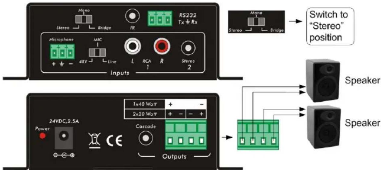
2x20W, 4-ohm speakers connection
3.3.2. Bridge connection: 1x40 Watt @ 8-ohm
The Audio Zone Amplifier has a bridge connection feature. It is used to double the output power to 40 Watt on a single 8-ohm speaker. It will sum up the input left and input right channels to a mono output with a maximum power of 40 Watt.

3.3.3. Dual-mono Output
The Audio Zone Amplifier has also the function of double-mono output. It can sum up the left and right channel, to two mono audio outputs. In this way, both outputs are showing the same mono audio signal.
The connection is as follows:

Dual 4-ohm speakers Mono connection
3.4. Connection of Microphone
The microphone input of the Audio Zone Amplifier has three modes. Different modes use different connections, as the picture below:

3.4.1. 48V phantom power input mode
When the Input Mode switch is set to “48V”, the MIC input will provide a 48V phantom power. This is usually used as a power supply for condenser microphone. MIC “+” connects to positive, “-” connects to negative and “ ± ” to ground.
Note: In this mode, please only connect a condenser microphone.
3.4.2. MIC input mode
When the Input Mode switch is set to "MIC", the MIC input is set for connecting with a dynamic microphone. There are two different connections possible:
1) Unbalanced connection:
Connect “ ± ”to ground, and “-” to signal.
Connect “ ± ”to ground, and “+” to signal.
2) Balanced connection: Connect "+" to positive, "-" to negative and "±" to ground.
3.4.3. LINE input mode
When the Input Mode switch is set to "LINE", the MIC input is set for connecting with normal audio or wireless microphone output. There are two different connections possible:
1) Unbalanced connection:
Connect “±” to ground, and “-” to signal.
Connect “ ± ” to ground, and “+” to signal.
2) Balanced connection: Connect "+" to positive, "-" to negative and "±" to ground.
4. Operation of the Control Panel and the IR Remote
4.1. Operation of the Control Panel
The pushbuttons on the top of the unit provide the control of audio switching, volume, and equalization (EQ).

4.1.1. Audio switching
There are two switchable stereo audio inputs, one 2xRCA input, and one 3.5mm Jack input. The control is made by the "Input Select" pushbuttons located on the top of the unit:
• Select input 1 to switch to RCA L/R Audio Input
- Select input 2 to switch to 3.5mm Stereo Input

4.1.2. Volume and Equalization control
The Line volume and the MIC volume can be controlled by the pushbuttons.
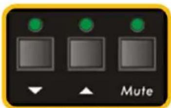
The MIC Volume/LINE volume/LINE bass/LINE treble will be selected by the function pushbuttons, and controlled up/down/mute by the action pushbuttons. Please check the picture below:
For example, to turn up the Line volume, you should first select the "LINE", and then press the "UP arrow" pushbutton.

flowchart
graph TD
    A["Square"] --> B["MIC"]
    A --> C["Line"]
    A --> D["Bass"]
    A --> E["Treble"]
Function Select
Action Select
4.2. Using of the IR Remote
4.2.1. IR Remote buttons
Inputs Select:
- RCA dual audio
- 3.5mm Jack
Volume Control:
MIC: turn up/down the Microphone volume
LINE: turn up/down the Line volume
BASS: Bass tuning
TREBLE: Treble tuning
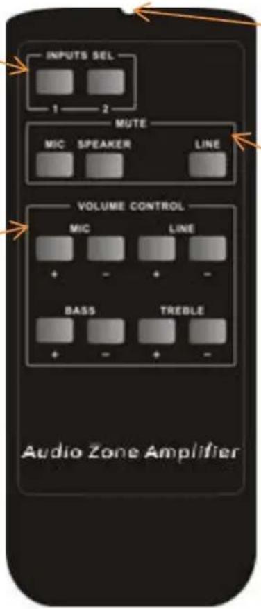
IR Emitter: IR device used to transmit the IR remote infrared signal
Mute:
MIC: Mute the Microphone volume.
LINE: Mute the Line volume.
SPEAKER: Unmute
IR Sensor head, works in conjunction with the IR remote. Please point the IR remote at the IR Sensor.

natural_image
Close-up of a black cordless audio headset with a small connector, isolated on white background (no text or symbols visible)3.5mm Jack, to connect the IR Sensor to the amplifier.
Note: The IR remote, the IR sensor, and the battery of the IR remote are optional and offered separately.
4.2.2. IR Remote codes
The remote control uses NEC format with the user code 40FF.
Input Select 1 = Code 04; Input Select 2 = Code 46;
Mute MIC = 02; Unmute = 03; Mute Line = 44;
MIC+ = 48, MIC- = 5C; Line+ = 1B; Line- = 5A; Bass+ = 58; Bass- = 59; Treble+ = 15;
Treble- = 54
5. Operations of RS232 Control
You can use a terminal software to control the 500216. Please set the parameters of the COM Port (baud rate, data bit, stop bit and the parity bit) to 9600, 8, 1, none.
5.1. RS232 Communication Commands
Communication protocol: RS232 Communication Protocol
| Command | Function Description | Feedback Code |
| 1A1. | Switching the audio to input 1 (RCA) | A: 1 -> 1 |
| 2A1. | Switching the audio to input 2 (3.5mm) | A: 2 -> 1 |
| 0A0. | Mute Audio for MIC and Line out | Mute |
| 1A0. | Mute Audio for MIC | Mute MIC |
| 2A0. | Mute Audio for Line out | Mute LIN |
| 0A1. | Unmute Audio | Unmute |
| 3A0. | Switch ON Noise Gate | Gate On |
| 4A0. | Switch OFF Noise Gate | Gate Off |
| 600% | Checking the working status | A: 1 -> 1Volume: 30Bass: 00Treble: 00 |
| 601% | MIC volume up | Volume of MIC: 51 |
| 602% | MIC volume down | Volume of MIC: 50 |
| 603% | Line volume up | Volume of LINE: 51 |
| 604% | Line volume down | Volume of LINE: 50 |
| 605% | Bass level up | Bass of LINE: 04 |
| 606% | Bass level down | Bass of LINE: 03 |
| 607% | Treble level up | Treble of LINE: 04 |
| 608% | Treble level down | Treble of LINE: 03 |
| 609% | Initialization, back to default settings | Init OK |
| 5[x][x]% | Preset MIC Volume, [xx] ranges from [00] to [60]. (Total of 61 levels) | Volume of MIC: 50 |
| 7[x][x]% | Preset line Volume, [xx] ranges from [00] to [60]. (Total of 61 levels) | Volume of LINE: 50 |
| 8[x][x]% Preset the Bass level, [xx] ranges from [00] to [08]. (Total of 9 levels) | Bass of LINE: 04 | |
| 9[x][x]% | Preset the Treble level, [xx] ranges from [00] to [08]. (Total of 9 levels) | Treble of LINE: 04 |
Note:
- The info inside brackets [ ] is a variable code. The brackets [ ] are not included.
- Any dot “.” or percent “%” sign after the command is part of the command.
Panel Drawing 6.

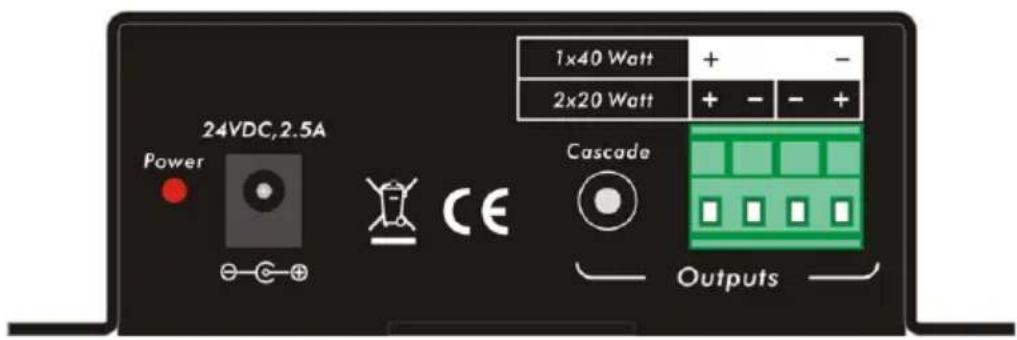
7. Troubleshooting & Maintenance
The following table describes some of the symptoms, probable causes and possible solutions in respect to the installation of the 500216 Audio Zone Amplifier.
| Problems Causes Solutions | ||
| No Audio Output | No signal at the input or output end | Check with an oscilloscope or multi-meter to check if there is any signal at the input or output end. |
| Failed or loose connection | Make sure the connection is good. | |
| The product is broken | Send it to authorized dealer for repairing. | |
| POWER indicator doesn't light or there is no response to any operation | Failed connection of power cord. | Make sure the power cord connection is good. |
| Interference in the output sound | Bad grounding | Check the grounding and make sure it is well connected. |
| Static becomes stronger when connecting the video connectors | Bad grounding | Check the grounding and make sure it is well connected. |
| Cannot control the device through RS232 port | Wrong RS232 communication parameters | Type in correct RS232 communication parameters |
| Broken RS232 port | Send it to authorized dealer for checking. | |
| Cannot control the device by RS232, IR remote, or front panel pushbuttons | The device has already been broken. | Send it to authorized dealer for repair. |
If you still cannot diagnose the problem, please call MuxLab Customer Technical Support at 877-689-5228 (toll-free in North America) or (+1) 514-905-0588 (International).
Regulatory Compliance
Disclaimer
Information in this document is subject to change without notice. The manufacturer does not make any representations or warranties (implied or otherwise) regarding the accuracy and completeness of this document and shall in no event be liable for any loss of profit or any other commercial damage, including but not limited to special, incidental, consequential, or other damages.
No part of this document may be reproduced or transmitted in any form by any means, electronic or mechanical, including photocopying, recording or information recording and retrieval systems without the express written permission of the manufacturer.
All brand names and product names used in this document are trademarks, or registered trademarks of their respective holders.
CE/FCC & Recycling Information
CE Certification
This equipment complies with the requirements relating to Electromagnetic Compatibility Standards EN55022/EN55024 and the further Standards cited therein. It must be used with shielded cables only. It has been manufactured under the scope of RoHS compliance.
FCC Certification
This equipment has been tested and found to comply with the limits for a Class B digital device, pursuant to part 15 of the FCC Rules. These limits are designed to provide reasonable protection against harmful interference in a residential installation. You are cautioned that changes or modification not expressly approved by the party responsible for compliance could void your authority to operate the equipment.
This device complies with part 15 of the FCC Rules. Operation is subject to the following two conditions:
-
This device may not cause harmful interference, and
-
This device must accept any interference received, including interference that may cause undesired operation

WEEE (Waste of Electrical and Electronic Equipment), Recycling of Electronic Products
In 2006 the European Union introduced regulations (WEEE) for the collection and recycling of all waste electrical and electronic equipment. It is no longer allowable to simply throw away electrical and electronic equipment. Instead, these products must enter the recycling process.
Each individual EU member state has implemented the WEEE regulations into national law in slightly different ways. Please follow your national law when you want to dispose of any electrical or electronic products. More details can be obtained from your national WEEE recycling agency.
CEFC
MuxLab PRODIGITAL™
8495 Dalton Road, Mount Royal, Quebec, Canada. H4T 1V5
Tel: (514) 905-0588
Fax: (514) 905-0589
Toll Free (North America): (877) 689-5228
E-mail: videoease@muxlab.com
URL: www.muxlab.com

- Audio Zone Amplifier 2 x 20 watts
- Installation Guide
- SAFETY PRECAUTIONS
- Contents
- Introduction ......4
- Specification....6
- System Connection....7
- Connection of Microphone....9
- Operation of the Control Panel and the IR Remote....10
- Using of the IR Remote....11
- Operations of RS232 Control 12
- Panel Drawing....13
- Troubleshooting & Maintenance....14
- Regulatory Compliance 15
- Introduction 1.
- Introduction to the 500216
- Features
- Package Content
- Specification
- System Connection 3.
- Safety Precautions
- System Diagram
- Audio Output
- Default output: 2x20 Watt @ 4-ohm
- Bridge connection: 1x40 Watt @ 8-ohm
- Dual-mono Output
- Connection of Microphone
- 48V phantom power input mode
- MIC input mode
- LINE input mode
- Operation of the Control Panel and the IR Remote
- Operation of the Control Panel
- Audio switching
- Volume and Equalization control
- Using of the IR Remote
- IR Remote buttons
- Inputs Select:
- Volume Control:
- Mute:
- IR Remote codes
- Operations of RS232 Control
- RS232 Communication Commands
- Note:
- Troubleshooting & Maintenance
- Regulatory Compliance
- CE/FCC & Recycling Information
- CE Certification
- FCC Certification
- WEEE (Waste of Electrical and Electronic Equipment), Recycling of Electronic Products
- MuxLab PRODIGITAL™
Brand : MuxLab
Model : 500216
Category : Receiver