
UMC16B-A1B1 - Microphone Lectrosonics - Free user manual and instructions
Find the device manual for free UMC16B-A1B1 Lectrosonics in PDF.


| Product Type | Digital Wireless Microphone Transmitter |
| Brand | Lectrosonics |
| Model | UMC16B-A1B1 |
| Frequency Range | 470–614 MHz (UHF TV Band) |
| RF Power Output | 50 mW (selectable to 10 mW) |
| Battery Type | 2× AA alkaline or rechargeable NiMH |
| Battery Life | Up to 6 hours (alkaline) |
| Dimensions (H×W×D) | 3.5 × 2.2 × 0.9 in (89 × 56 × 23 mm) |
| Weight (without batteries) | 5.3 oz (150 g) |
| Audio Input Connector | TA5M (locking 5-pin) |
| Modulation | Digital (Licensed Digital Hybrid™) |
| Audio Frequency Response | 30 Hz – 20 kHz ±1 dB |
| Dynamic Range | > 120 dB (A-weighted) |
| Operating Temperature | –20°C to +50°C |
| Microphone Type Compatibility | Lavalier, headset, or instrument |
| Power Management | Auto-off timer, low battery indicator |
| Security Features | Encryption (AES-256) |
| Maintenance | Clean with dry soft cloth; replace batteries when depleted |
| Spare Parts Available | Belt clip, TA5M connectors, battery cover |
| Reparability | Modular design; field-replaceable battery contacts |
Frequently Asked Questions - UMC16B-A1B1 Lectrosonics
User questions about UMC16B-A1B1 Lectrosonics
0 question about this device. Answer the ones you know or ask your own.
Ask a new question about this device
Download the instructions for your Microphone in PDF format for free! Find your manual UMC16B-A1B1 - Lectrosonics and take your electronic device back in hand. On this page are published all the documents necessary for the use of your device. UMC16B-A1B1 by Lectrosonics.
USER MANUAL UMC16B-A1B1 Lectrosonics
Includes updated models:
UMC16B
UMC16BL
UMC16B-A1B1
UMC16B-941

(all models same appearance except for front panel engraving)

Follow Us On:


Fill in for your records:
Serial Number:
Purchase Date:

Table of Contents
Introduction......3
Antenna Use and Placement 5
Accessory Antennas....5
Specifications 6
Service and Repair 6
Introduction
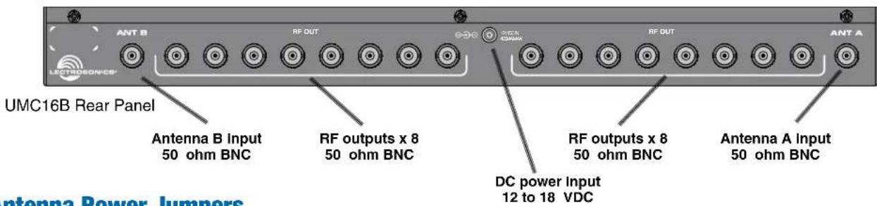
The UMC16B multi-coupler is used to distribute the signals from two antennas to eight diversity receivers to minimize the amount of cabling and antennas needed in multi-channel wireless systems. The design combines broad band ceramic filtering with low noise, high intercept point RF distribution to provide outstanding performance and flexibility. Up to eight diversity receivers or up to 16 non-diversity receivers can be utilized across a 230 MHz passband.
Various models are available, covering different frequency bands in the UHF spectrum.
The UMC16B can be powered from an external supply, 10 to 18 VDC for mobile applications, or from 100 to 240 VAC for installations using the regulated power supply furnished with the unit. A locking connector on the rear panel secures the power connection.
The RF signals at the inputs first pass through a ceramic filter to block energy above and below the passband. The signal is then fed to a high current amplifier to apply the gain needed ahead of the splitter. The amplifier is a high current type with a very high IP3 (third order intercept) that minimizes intermodulation products.
The amplifier output is then distributed to the output jacks using a Wilkinson "strip line" RF splitter. Unused outputs should be terminated with 50 Ohm dummy loads for maximum performance, however, the splitter design allows unused jacks to remain un-terminated with only a slight effect on other channels (+/- 1 to 2 dB in the level at the outputs).
The unit is housed in a standard 19 inch rack mount assembly with rugged connectors.
![graph TD A["Input A IN"] --> B["Ceramic Resonator Filter"] B --> C["Low Noise Amp"] C --> D["Strip Line RF Power Divider"] D --> E["A OUT"] E --> F["Output"]](/content/2026/05/1059396/images/85486f8f3f8e141222c328e322f17010dec76eab837fc3531c7a35043ed1983e.jpg)
UMC16B RF Signal Distribution
![graph TD A["Strip Line RF Power Divider"] --> B["Low Noise Amp"] B --> C["Ceramic Resonator Filter"] C --> D["B IN"] E["B OUT"] --> F["Output"]](/content/2026/05/1059396/images/c5198e32385ce2bbe1ef45adfe0d9d0c58ca619743bdbbca396ea6b2e73eb3dd.jpg)
Antenna Power Jumpers
NOTE: These jumpers are ONLY to be used to power the RF amp in a Lectrosonics UFM Series filter/amp module or ALP Series Active LPDA antenna through the coaxial cable
For long cable runs between the UMC16B and remote RF amplifiers, gain must be applied at the antenna end of the coaxial cable to compensate for the loss that occurs over the length of the cable run. This applies the gain before the loss in the coaxial cable run to maximize the signal to noise ratio. The filter/amp modules can be placed in an optimum position close to the antenna and powered by DC from the UMC16B via the coaxial cable. Jumpers at the antenna inputs on the multicoupler apply DC voltage on the coaxial cable to power the filter/amp modules and active LPDA antennas.
- To enable the DC antenna power, unplug the power cord and remove the cover (12 screws).
- Locate the jumpers on the circuit board. When the jumper is inserted toward the outside of the unit, power is disabled. Inserted toward the inside of the unit, power is enabled.

![graph TD A["Triple socket jumper toward outside to disable antenna power"] --> B["Antenna Power"] C["Triple socket jumper toward inside to enable antenna power"] --> D["Antenna Power"] E["Double socket jumper toward outside to disable antenna power"] --> F["Antenna Power"] G["Double socket jumper to…](/content/2026/05/1059396/images/0c985c178296355c2ac5775cd64ca01e8f8bc03545e6dbbd975f20a67e9d7657.jpg)
NOTE: If a splitter/combiner is used between the remote device and the multicoupler, DC power will not pass through to the antennas. In this case, a power supply or BIAS-T is needed for the active antenna or filter/amp.
Antenna Use and Placement
Try to position the antennas so that they are not within 3 or 4 feet of large metal surfaces. It is also good to maintain a direct “line of sight” between the transmitter and the receiver antennas. In situations where the operating range is less than about 50 feet, the antenna positioning is much less critical.
A wireless transmitter sends a radio signal out in all directions. This signal will often bounce off nearby walls, ceilings, metal surfaces, etc. and a strong reflection can arrive at the receiver antenna along with the direct signal. When the direct and reflected signals are out of phase with each other a cancellation will occur as the signals mix at the antenna input, resulting in what is known as a “multipath drop-out.”
At UHF frequencies, a drop-out usually sounds like a brief noise burst, click, pop, or something similar. In severe cases, it may result in a complete loss of the carrier and the sound. A drop-out situation may be either better or worse as a crowd fills and/or leaves the room, or when the transmitter and receiver antennas are moved to different locations.
Diversity receiver designs apply various circuitry to select or combine two antennas to reduce or eliminate multipath drop-outs. The antennas must be placed at least a half wavelength apart to achieve a noticeable reduction in drop-outs, or several feet apart for the maximum benefit. It is generally best to use two antennas of the same type for diversity reception, especially with phase combining diversity designs.
Diversity reception works largely because it is unlikely that drop-outs will occur simultaneously at two antennas that are spaced more than a half wavelength apart. Ratio and phase combining designs add the antenna signals together which provides a stronger signal to the receiver when both antennas are somewhat weak.
The diagram below depicts a classic multipath drop-out situation. The drawing is simplified to illustrate the concept of phase cancellation. In reality, indoors or with nearby reflective surfaces like metal buildings and vehicles, both antennas receive multiple direct and reflected signals.
![graph TD A["REFLECTIVE SURFACE"] --> B["INDIRECT SIGNAL"] B --> C["MULTICOUPLER"] D["TRANSMITTER"] --> E["PHASE CANCELLATION"] E --> F["INDIRECT SIGNAL"] F --> G["INDIRECT SIGNAL"] G --> H["INDIRECT SIGNAL"] H --> I["INDIRECT SIGNAL"] I --> J["INDIRECT SIGNAL"] J --> K["INDIRECT SIGNAL"] K --> L["IN…](/content/2026/05/1059396/images/37d17804c770a417dff053b19abb691557272ee212b9cbbfd07825b8601acb51.jpg)
Accessory Antennas
The UMC16B will operate with any 50 ohm antenna with a BNC connector, provided the antenna is tuned to the same frequency band. The SNA600a model shown here is a versatile, collapsible dipole antenna that provides a circular coverage pattern and a 100 MHz passband. The elements are tuned to frequency by adjusting the length of the radials according to a scale printed along the feed line.
The antenna is supplied in a kit that includes a mounting stud, hardware and bracket. The machined aluminum mounting block provides tapped holes for a microphone stand or 3/8-16 thread, and can be rotated in 90 degree increments. The supplied bracket can be bent into a variety of shapes for mounting on horizontal or vertical surfaces.

Specifications
Type: Active RF distribution system with ceramic filtering
Inputs: Two 50 Ohm BNC jacks on rear panel
Third order intercept: +27dBm at input
Outputs:
Type: 16 BNC jacks on rear panel. Eight jacks per antenna.
Isolation: 20 dB min, any output to any output Any output can be open, shorted, or terminated without affecting other outputs.
Splitter type: Wilkinson 1/4 wave strip-line
Filter passband: UMC16B: 537 to 768 MHz (blocks 21 to 29)
UMC16BL: 470 to 692 MHz (blocks 470 to 26)
UMC16B-A1B1: 470 to 615 MHz (bands A1, B1)
UMC16B-941: 941 to 960 MHz (block 941)
(See serial number sticker on side panel for frequency range of your particular unit.)
Input/Output RF gain: 0 dB nominal
In-Band Ripple: +/-2 dB
Temperature Range: -20C to +50C
Power Requirements: 10 to 18 VDC; overload protection provided by internal auto resetting poly fuse
Power consumption: Nominally 500 mA at 15V DC
Dimensions: 19 x 7.1 x 1.75 inches (487 x 180 x 45 mm)
Weight: 3.2 lbs.; 1.45 kg.
Specifications subject to change without notice.
Service and Repair
If your system malfunctions, you should attempt to correct or isolate the trouble before concluding that the equipment needs repair. Make sure you have followed the setup procedure and operating instructions. Check the inter-connecting cables.
We strongly recommend that you do not try to repair the equipment yourself and do not have the local repair shop attempt anything other than the simplest repair. If the repair is more complicated than a broken wire or loose connection, send the unit to the factory for repair and service. Don't attempt to adjust any controls inside the units. Once set at the factory, the various controls and trimmers do not drift with age or vibration and never require readjustment. There are no adjustments inside that will make a malfunctioning unit start working.
LECTROSONICS service department is equipped and staffed to quickly repair your equipment. In-warranty repairs are made at no charge in accordance with the terms of the warranty. Out of warranty repairs are charged at a modest flat rate plus parts and shipping. Since it takes almost as much time and effort to determine what is wrong as it does to make the repair, there is a charge for an exact quotation. We will be happy to quote approximate charges by phone for out of warranty repairs.
Returning Units for Repair
You will save yourself time and trouble if you will follow the steps below:
A. DO NOT return equipment to the factory for repair without first contacting us by letter or by phone. We need to know the nature of the problem, the model number and the serial number of the equipment. We also need a phone number where you can be reached 8 am to 4 pm (Mountain Standard Time). B. After receiving your request, we will issue you a return authorization number (R.A.). This number will help speed your repair through our receiving and repair departments. The return authorization number must be clearly shown on the outside of the shipping container. C. Pack the equipment carefully and ship to us, shipping costs prepaid. If necessary, we can provide you with the proper packing materials. UPS is usually the best way to ship the units. Heavy units should be "double-boxed" for safe transport. D. We also strongly recommend that you insure the equipment, since we cannot be responsible for loss of or damage to equipment that you ship. Of course, we insure the equipment when we ship it back to you.
Lectrosonics USA:
Mailing address:
Lectrosonics, Inc.
PO Box 15900
Rio Rancho, NM 87174
USA
Shipping address:
Lectrosonics, Inc.
581 Laser Rd.
Rio Rancho, NM 87124
USA
Telephone:
(505) 892-4501
(800) 821-1121 Toll-free
(505) 892-6243 Fax
Web:
www.lectrosonics.com
E-mail:
sales@lectrosonics.com
Lectrosonics Canada:
Mailing Address:
720 Spadina Avenue, Suite 600
Toronto, Ontario M5S 2T9
Canada
Telephone:
(416) 596-2202
(877) 753-2876 Toll-free
(877-7LECTRO)
(416) 596-6648 Fax
E-mail:
Sales: colinb@lectrosonics.com
Service: joeb@lectrosonics.com
LIMITED ONE YEAR WARRANTY
The equipment is warranted for one year from date of purchase against defects in materials or workmanship provided it was purchased from an authorized dealer. This warranty does not cover equipment which has been abused or damaged by careless handling or shipping. This warranty does not apply to used or demonstrator equipment.
Should any defect develop, Lectrosonics, Inc. will, at our option, repair or replace any defective parts without charge for either parts or labor. If Lectrosonics, Inc. cannot correct the defect in your equipment, it will be replaced at no charge with a similar new item. Lectrosonics, Inc. will pay for the cost of returning your equipment to you.
This warranty applies only to items returned to Lectrosonics, Inc. or an authorized dealer, shipping costs prepaid, within one year from the date of purchase.
This Limited Warranty is governed by the laws of the State of New Mexico. It states the entire liability of Lectrosonics Inc. and the entire remedy of the purchaser for any breach of warranty as outlined above. NEITHER LECTROSONICS, INC. NOR ANYONE INVOLVED IN THE PRODUCTION OR DELIVERY OF THE EQUIPMENT SHALL BE LIABLE FOR ANY INDIRECT, SPECIAL, PUNITIVE, CONSEQUENTIAL, OR INCIDENTAL DAMAGES ARISING OUT OF THE USE OR INABILITY TO USE THIS EQUIPMENT EVEN IF LECTROSONICS, INC. HAS BEEN ADVISED OF THE POSSIBILITY OF SUCH DAMAGES. IN NO EVENT SHALL THE LIABILITY OF LECTROSONICS, INC. EXCEED THE PURCHASE PRICE OF ANY DEFECTIVE EQUIPMENT.
This warranty gives you specific legal rights. You may have additional legal rights which vary from state to state.
Brand : Lectrosonics
Model : UMC16B-A1B1
Category : Microphone