Machete MA-OGO2500.1D Sport - Receiver Deaf Bonce - Free user manual and instructions
Find the device manual for free Machete MA-OGO2500.1D Sport Deaf Bonce in PDF.


| Product Type | Monoblock Car Audio Amplifier |
| Model | Machete MA-OGO2500.1D Sport |
| Brand | Deaf Bonce |
| RMS Power Output (4 Ohm) | 2500 W x 1 |
| RMS Power Output (2 Ohm) | 4000 W x 1 |
| RMS Power Output (1 Ohm) | 5000 W x 1 |
| Frequency Response | 10 Hz – 250 Hz |
| Low Pass Filter | 40 Hz – 250 Hz, adjustable |
| Subsonic Filter | 10 Hz – 40 Hz, adjustable |
| Bass Boost | 0 – 12 dB at 45 Hz |
| Remote Bass Control | Included (wired) |
| Input Sensitivity | 0.3 V – 5 V |
| Signal-to-Noise Ratio | >100 dB |
| Total Harmonic Distortion (THD) | <0.01% |
| Damping Factor | >300 at 100 Hz |
| Impedance Stability | 1 Ohm stable |
| Dimensions (L x W x H) | 14.5 x 7.5 x 2.5 in (368 x 191 x 63 mm) |
| Weight | 8.6 lb (3.9 kg) |
| Recommended Fuse Size | 300 A (ANL or AGU) |
| Power Supply Voltage | 10 – 15 V DC |
| Main Functions | Low-pass filter, subsonic filter, bass boost, remote bass control, phase shift |
| Maintenance & Cleaning | Keep ventilation clear. Clean with dry cloth. Avoid moisture. |
| Safety Precautions | Disconnect battery before installation. Use proper gauge wiring. Ensure adequate ventilation. |
| Spare Parts & Repairability | Contact authorized dealer for service. No user-serviceable parts inside. |
Frequently Asked Questions - Machete MA-OGO2500.1D Sport Deaf Bonce
User questions about Machete MA-OGO2500.1D Sport Deaf Bonce
0 question about this device. Answer the ones you know or ask your own.
Ask a new question about this device
Download the instructions for your Receiver in PDF format for free! Find your manual Machete MA-OGO2500.1D Sport - Deaf Bonce and take your electronic device back in hand. On this page are published all the documents necessary for the use of your device. Machete MA-OGO2500.1D Sport by Deaf Bonce.
USER MANUAL Machete MA-OGO2500.1D Sport Deaf Bonce
- Introduction
- Safety instructions
- Typical installation sequence
- Connection methods
- Wiring diagrams
- Selection of the diameter of power cables and speaker cables
- Specifications
- Possible faults and their solutions
- Box contents
-
Warranty and maintenance info
-
Information on disposal of the electrical and electronic equipment (for the European countries with separate waste collection)
1. INTRODUCTION
Thank you for purchasing this Deaf Bonce product of Machete Sport series! Our company is committed to the creation of extremely high-profile systems with no loss of quality.
To ensure proper use, please carefully read through this manual before using this product. It is especially important that you read and observe caution's in this manual. Please keep the manual in a safe and accessible place for future reference.
2. SAFETY INSTRUCTIONS
- Make sure that your vehicle has a 12V DC electrical system with negative grounding. Before installing the amplifier in cars, trucks or buses, check the battery voltage.
- Check the state of on-board power supply of your vehicle, the battery and the alternator. When the engine is running, depending on the ambient temperature, the voltage to be outputted by the alternator must be within the range of 14 to 14.7 V. Open circuit voltage (OCV) of the battery must be within the range of 12.5 to 13 V. Make sure that the rated current of the alternator and the battery capacity is enough to provide increased consumption.
For example, for the power of the amplifier 1000 W, the rated current of the alternator is required at the rate of 1000 W / 13 V = 77 amperes. A more powerful amplifier requires a more powerful alternator as well as an additional battery.
3. Do not place the amplifier in the engine compartment and also in the places exposed to water, moisture, dust or dirt.
4. Never stretch the cables outside of the car and near the moving parts of the car. This can lead to destruction of the insulating layer, short circuit and fire.
5. The amplifier should be installed in areas of the car where the temperature varies from 0 °C (32 °F) to 55 °C (131 °F). The amplifier should be in a place with a good air circulation. The horizontal position of the amplifier is the best way to install.
6. During the operation the amplifier may be heated up to 80 °C (176 °F). Before you touch it, make sure it is not overheated that may be dangerous.
7. To improve the cooling of the amplifier, it is recommended to clean periodically the heatsink from dust. When cleaning the heatsink strong solvents should not be used as they may damage the amplifier. Do not use compressed air, because solids can penetrate inside the amplifier. Cleanings best done with wet towels or cloth.
8. Make sure that the location of the amplifier does not violate the proper operation of mechanical and electrical devices of the vehicle.
9. Make sure that during the installation and connection of the battery, the power cables are not shorted.
10. When performing plumbing, drilling or cutting works with the car, make sure that there is no wiring, brake lines, fuel pipe or other structural elements under the place of work. Follow the safety rules! Use protective glasses and gloves.
11. To protect the wires use rubber gaskets if the wire passes through a hole in the plate, or other similar materials if it lies close to the parts exposed to heat.
12. Make sure that all the cables are fixed over the entire length. Also make sure that their outer protective shell is non-combustible. Use a clamping screw to secure the positive and negative cables next to the appropriate terminals of the amplifier.
13. Select a diameter of the power cable in accordance with the power of the amplifier and the recommendations provided here. Power cables are extremely important since they directly affect the system damping factor and sound quality. The cables to the battery must be in the copper crimp terminals pressed with the help of a hydraulic press, and well fixed to the battery terminals.
14. To avoid accidental damage, keep the amplifier in its original packaging prior to installation.
15. Use high-quality copper speaker and power cables.
CAUTION!!! High sound pressure can damage your health!
Please use the common sense when controlling volume!
3. TYPICAL INSTALLATION SEQUENCE
- Before installing the amplifier disconnect the battery from the electrical system.
- To connect the amplifier it is necessary to stretch the power cable from the location of the battery to the place of installation of the amplifier. Select the power cable with the appropriate regulations in AWG (see Table: Selection of the diameter of the power cables)
- Connect the power supply with the correct polarity. Connect all (+) terminals of the amplifier to the cables stretching from the positive terminal of the battery and all (-) terminals of the amplifier – to the cables stretching from the negative terminal of the battery.
-
Place the fuse holder for each positive cable within 40 cm from the positive terminal of the battery and connect one end of the power cable to the holder after connecting the other end to the amplifier. Do not install the fuse(s).
-
Route all signal cables next to each other and separately from the power cables.
-
Connect the wires of RCA input. The input signal power must be between 0.2 V and 6 V.
-
To connect the power wire supply is necessary to use special power cables.
-
Fasten the amplifier properly when installing it in the vehicle. If the component is disconnected during driving, it may cause serious damage to the passengers of the vehicle or another vehicle. It is not recommended to screw the amplifier directly to the metal it can lead to distortions at the signal outputs.
-
After installation is complete, check the wiring of the system and make sure that all connections have been made correctly. Before installing the fuses, disconnect the positive lead from the battery and then install the fuse in the fuse holder. Using the light bulb 12 V 21 W, connect the positive lead to one contact of the bulb and the other contact of the bulb to the positive terminal of the battery.
When properly connected, the bulb must briefly light up and go out. Now you may connect the positive lead to the (+) of the battery. If the light does not go out, then something is wrong. This will prevent damage to the amplifier in case of reverse polarity and unwanted sparks when connecting. Install the rest of the fuses.
10. To activate the amplifier, it is necessary to apply the positive potential of 12 volts to the control input of the amplifier (REM IN) through a switch or a corresponding control output (REMOTE OUT) with the head unit (HU).
11. LED indicator on the front panel lights up in green, indicating that the device is turned on. LED indicator lights up in red when the outputs are overloaded, if the temperature protection is activated, if there is a short circuit in the system cables to the heatsink and if the amplifier is faulty.
12. The sound level is calibrated by adjusting the volume of the source up to 3/4 of its maximum level. Then, adjust the sensitivity level of the amplifier up until you hear distortions.
4. CONNECTION METHODS
The minimum permissible load impedance at the output of the amplifier is 1 ohm.
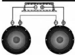
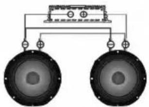
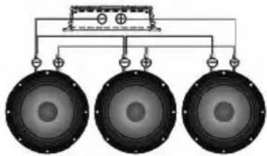
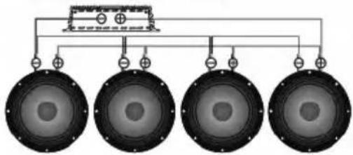
SPEAKERS WIRING DIAGRAMS
In any case do not expose the amplifier to the loads lower than specified by the manufacturer. Use these schematics to calculate load impedance of different connection types.
Serial connection of the speakers
natural_image
Diagram of a speaker system with two speakers and a central control panel (no text or labels)| Voice coil | Total impedance |
| 4 Ohm | 8 Ohm |
| 8 Ohm | 16 Ohm |
natural_image
Diagram of two speakers with a suspended platform (no text or symbols)akers
natural_image
Pure diagram of three speakers with connection lines, no text or symbols present| Voice coil | Total impedance |
| 4 Ohm | 2 Ohm |
| 8 Ohm | 4 Ohm |
natural_image
Pure electrical circuit lines without any symbols| Voice coil | Total impedance |
| 4 Ohm | 1.33 Ohm |
| 8 Ohm | 2.66 Ohm |
| Voice coil | Total impedance |
| 4 Ohm | 1 Ohm |
| 8 Ohm | 2 Ohm |
kers
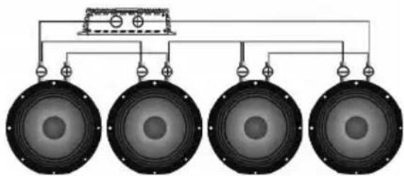
natural_image
Diagram of four identical speaker amplifiers connected to a top-mounted device (no text or labels)| Voice coil | Total impedance |
| 4 Ohm | 4 Ohm |
| 8 Ohm | 8 Ohm |
SUBWOOFERS WIRING DIAGRAMS
The minimum permissible load impedance at the output of the amplifier is 1 ohm. Use these formulas to calculate the load impedance of various types of connections.
Serial connection
Total impedance = ΩSub 1 + ΩSub 2 + ΩSub 3 ...
Parallel connection
Tot al im ped anc e = 1 Su b 11 + 1Su b 12 + ·s 1Su b 3
SCHEMES OF ENABLING THE LOAD OF THE SUBWOOFER
In any case do not expose the amplifier to the loads lower than specified by the manufacturer. Use these schematics to calculate load impedance of different connection types.
Voice coils 1+1, 2+2, 4+4 Ohm
The subwoofer has voice coil D1, D2 or D4.
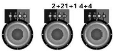
One subwoofer, coils in series
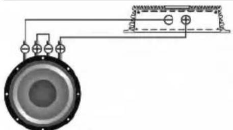
natural_image
Pure electrical circuit lines without any symbols| Voice coils | Total impedance |
| 1+1 Ohm | 2 Ohm |
| 2+2 Ohm | 4 Ohm |
| 4+4 Ohm | 8 Ohm |
One subwoofer, coils in parallel
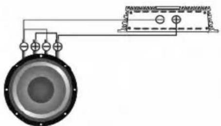
natural_image
Pure electrical circuit lines without any symbols| Voice coils | Total impedance |
| 1+1 Ohm | 0,5 Ohm |
| 2+2 Ohm | 1 Ohm |
| 4+4 Ohm | 2 Ohm |
Subwoofers in series, coils in parallel
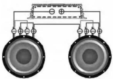
natural_image
Pure electrical circuit lines without any symbols| Voice coils | Total impedance |
| 1+1 Ohm | 1 Ohm |
| 2+2 Ohm | 2 Ohm |
| 4+4 Ohm | 4 Ohm |
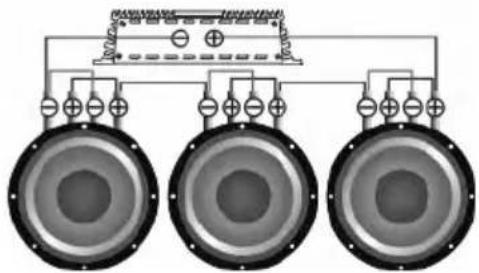
natural_image
Pure electrical circuit lines without any symbols| Voice coils | Total impedance |
| 1+1 Ohm | 1,5 Ohm |
| 2+2 Ohm | 3 Ohm |
| 4+4 Ohm | 6 Ohm |
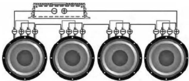
natural_image
Pure electrical circuit lines without any symbols| Voice coils | Total impedance |
| 1+1 Ohm | 2 Ohm |
| 2+2 Ohm | 4 Ohm |
| 4+4 Ohm | 8 Ohm |
EN
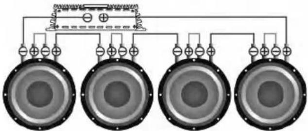
Subwoofers in series, coils in series
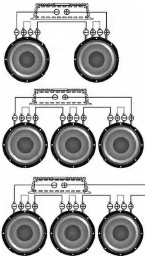
| Voice coils | Total impedance |
| 1+1 Ohm | 4 Ohm |
| 2+2 Ohm | 8 Ohm |
| 4+4 Ohm | 16 Ohm |
| Voice coils | Total impedance |
| 1+1 Ohm | 6 Ohm |
| 2+2 Ohm | 12 Ohm |
| 4+4 Ohm | 24 Ohm |
natural_image
Pure electrical circuit lines without any symbols| Voice coils | Total impedance |
| 1+1 Ohm | 8 Ohm |
| 2+2 Ohm | 16 Ohm |
| 4+4 Ohm | 32 Ohm |
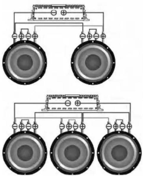
Subwoofers in parallel, coils in series
natural_image
Diagram of a speaker system with three speakers and connections (no text or labels)| Voice coils | Total impedance |
| 1+1 Ohm | 1 Ohm |
| 2+2 Ohm | 2 Ohm |
| 4+4 Ohm | 4 Ohm |
| Voice coils | Total impedance |
| 1+1 Ohm | 0,66 Ohm |
| 2+2 Ohm | 1,33 Ohm |
| 4+4 Ohm | 2,66 Ohm |
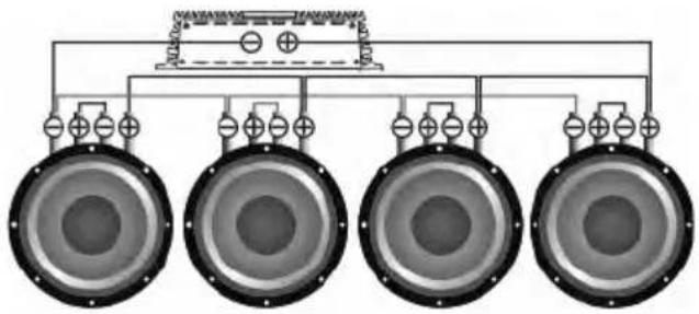
natural_image
Diagram of four speakers arranged in a row with no text or symbols| Voice coils | Total impedance |
| 1+1 Ohm | 0,5 Ohm |
| 2+2 Ohm | 1 Ohm |
| 4+4 Ohm | 2 Ohm |
EN
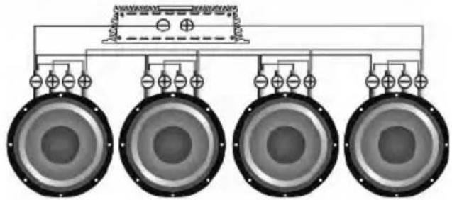
Subwoofers in parallel, coils in parallel
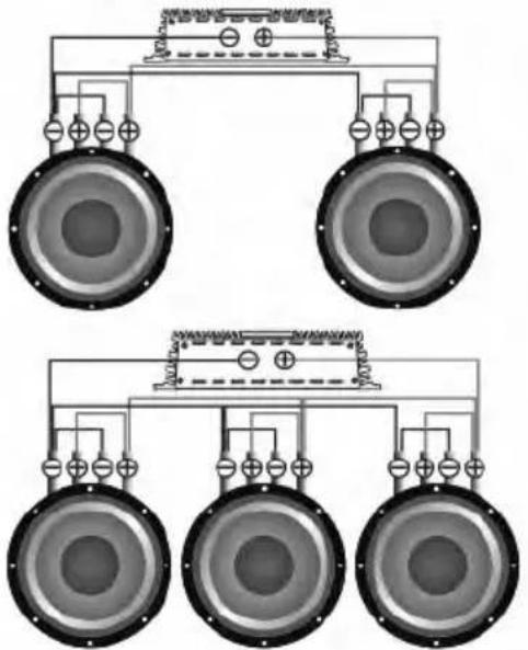
natural_image
Pure electrical circuit lines without any symbols| Voice coils | Total impedance |
| 1+1 Ohm | 0,25 Ohm |
| 2+2 Ohm | 0,5 Ohm |
| 4+4 Ohm | 1 Ohm |
natural_image
Pure electrical circuit lines without any symbols| Voice coils | Total impedance |
| 1+1 Ohm | 0,16 Ohm |
| 2+2 Ohm | 0,33 Ohm |
| 4+4 Ohm | 0,66 Ohm |
| Voice coils | Total impedance |
| 1+1 Ohm | 0,125 Ohm |
| 2+2 Ohm | 0, 5 Ohm2 |
| 4+4 Ohm | 0,5 Ohm |
CAUTION!!! High sound pressure can damage your health! Please use the common sense when controlling volume!
5. W I R I N G D I A G R A M S
Connect the head unit (HU) to low-level inputs of the amplifier using RCA cable.
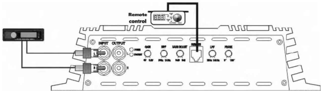
Connect the speaker cables from the positive and negative terminals of the speakers to the respective outputs of the amplifier terminal marked with SPEAKER, as shown at the diagram. To connect the power wire supply it is necessary to use special power cables. The fuse is placed in the holder and fixed in the cable cut. One end of the cable is connected to the positive terminal of the battery, the second one – to the amplifier terminals marked with +12V. Be sure to use a fuse with the parameters sufficient for use in the system.
EN
The length and diameter of the grounding cable must conform to the length and diameter of the cable + 12V. Connect one end to the negative terminal of the battery and the other end of the grounding cable to the terminals marked with GND.
Caution!!! The minimum permissible load impedance for single channel connection is 1 ohm. For models MA-OGO2500.1D Sport the operating voltage is 9-15 V.
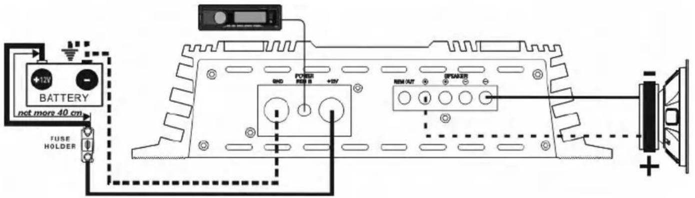
Application of connectors and controls
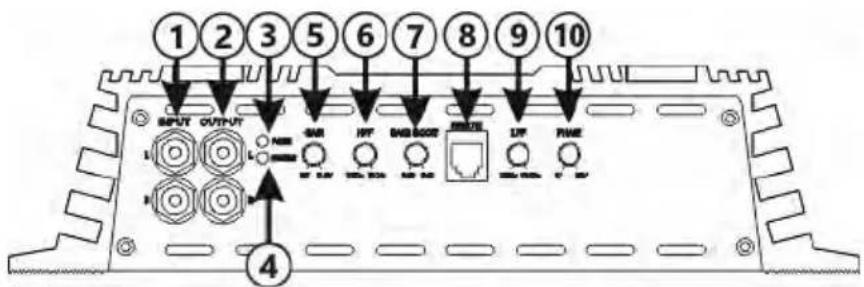
- INPUT – signal input, RCA jacks
- OUTPUT – signal, output RCA jacks
- POWER - LED for operation (green)
- PROTECT - LED for protection (red)
- GAIN - input signal level adjustment 0.2 V - 6 V
- HPF - high pass filter 10 Hz-1 kHz (24 dB/Oct)
- BASS BOOST - bass level adjustment 0-9 dB at 45 Hz
- REMOTE - input for connection of the bass remote control
- LPF - low pass filter 35 Hz-10 kHz (24 dB/Oct)
- PHASE - phase shifter 0° - 180°
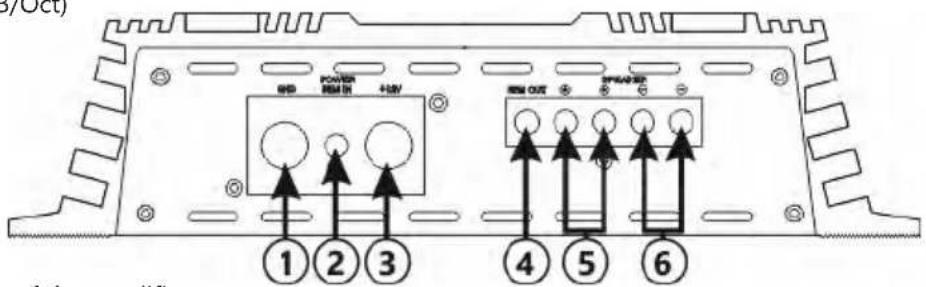
- GND - grounding supply terminal
- REM IN - connector of remote activation of the amplifier
- +12V - power supply terminal (+12V)
- REM OUT - connector of remote activation of the next amplifier
- SPEAKER "+" - speaker positive terminal connections
- SPEAKER "-" - speaker negative terminal connections
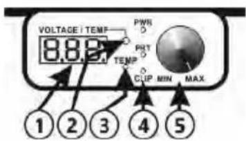
Remote control
- LED-Display - displays voltage and temperature readings
- VOLTAGE/TEMP - button to switch between voltage and temperature readings display
- TÉMP - temperature protection LED
- PWR - power LED, PRT - general protection LED, CLIP - clip LED
- Input signal controller
6. SELECTION OF THE DIAMETER OF POWER CABLES AND SPEAKER CABLES
EN
Sel e c tio n o f the di a mete r of th e p o wer c a bles
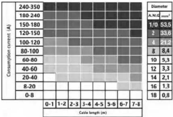
Use the table below to select the desired diameter based on the length and the current consumption.
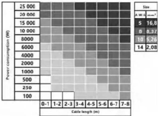
Use the table below to select the desired diameter based on the length and the power consumption.
7. SPECIFICATIONS
| Model MA-OGO2500.1D Sport | |
| Power RMS 4 Ohm* (W) | 750 x 1 |
| Power RMS 2 Ohm* (W) | 1500 x 1 |
| Power RMS 1 Ohm* (W) | 2500 x 1 |
| Power RMS 1 Ohm** (W) | 2700 x 1 |
| Crossover (dB / Oct) | 24 |
| Low pass filter (Hz) | 35 - 10 000 |
| High pass filter (Hz) | 10 - 1 000 |
| Bass level adjustment (bass boost) (dB at 45 Hz) | 0 - 9 |
| Phase (degrees) | 0 - 180 |
| Frequency response (+/- 1 dB) (Hz) | 10 - 10 000 |
| Input sensitivity (V) | 0.2 - 6 |
| Signal to noise ratio (dB) | >95 |
| Damping factor | >200 |
| Input terminal connection (AWG / mm2) | 0 / 53.3 |
| Output terminal connection (AWG / mm2) | 8 / 8.4 |
| Minimum permissible load impedance on the single channel (Ohm) | 1 |
| Working voltage (V) | 9 - 15 |
| Size (WxLxH mm) | 415 x 259 x 61 |
| Size (WxLxH inch) | 16.34 x 10.2 x 2.4 |
*RMS Power at 14.4 V, THD 1%,
**RMS Power at 15 V, THD 1%
8. POSSIBLE FAULTS AND THEIR SOLUTIONS
Deaf Bonce amplifiers are high-quality and technically perfect products. The problems often arise due to improper use, faulty connection of components or lack of power supply of the on-board network.
1) The amplifier does not turn on.
Problem solution: Check all the contacts and the presence of 9-15 V at the amplifier terminals. Check whether the control input of the amplifier "REM IN" receives the positive potential of 12 V.
2) Power turns on, but goes into protection (security indicator lights up).
Problem solution: Check if there is a short circuit (fault) on the amplifier output which is connected to the speakers or subwoofers. Make sure that commutation of the voice coils of the subwoofer is correct. The rated impedance of the voice coils should not be lower than the permissible rated load impedance of the amplifier. Check the supply voltage of the amplifier. It must be within the range of 9-15 V.
3) The amplifier turns on but at a high volume it goes to protection.
Problem solution: The amplifier may lack power. Make sure that the rated current of the alternator and the battery capacity is enough to power this amplifier.
Check the amplifier for overheating. Check the load impedance.
4) The amplifier is turned on, but there is no sound from the speakers or subwoofer.
Problem solution: Check the connection of the amplifier, the integrity of the interconnecting cable, HU, the speaker or the subwoofer.
9. BOX CONTENTS
- Amplifier - 1 pcs.
- Owner's Manual - 1 pcs.
- Warranty card - 1 pcs.
- Mounting Kit - 1 pcs.
- Remote control - 1 pcs.
10. W A R R A N T Y A N D M A I N T E N A N C E I N F O
Deaf Bonce products are warranted against defects concerning materials and their manufacturing under normal functioning conditions.
While the product is under warranty, defective parts will be repaired or replaced at the manufacturer's discretion. The defective product, along with notification about it, must be returned to the dealer from which it was purchased together with the warranty certificate duly filled in, complete with the original packaging. If the product is no longer under warranty, it will be repaired at the current costs.
Our company does not undertake any liability for damages due to transportation. Our company does not take any responsibility for: costs or loss of profit due to the impossibility to use the product, other accidental or consequential costs, expenses or damages suffered by the customer. Warranty according to laws in force. For more information visit our website and carefully read warranty card. The manufacturer reserves the right to change design and specification without prior notice.
11. IN FORMATION ON DISPOSAL OF THE ELECTRICAL AND ELECTRONIC EQUIPMENT (FOR THE EUROPEAN COUNTRIES WITH SEPARATE WASTE COLLECTION)
Items marked "crisscrossed wheeled bin" are not allowed to be disposed of together with usual household waste. These electrical and electronic products should be disposed of in special reception centers, equipped for recycling such products and components. For information about the location of the nearest disposal / recycling spot and the rules of delivery of waste please contact your local municipal office. Recycling and proper disposal helps to protect the environment and prevent harmful effects on health.


СОДЕРЖАНИЕ
natural_image
Diagram of a speaker system with two speakers and a suspended load (no text or labels)natural_image
Diagram of a multi-tiered audio system with multiple speakers and connections (no text or labels)natural_image
Pure electrical circuit lines without any symbolsnatural_image
Pure electrical circuit lines without any symbolsnatural_image
Pure electrical circuit lines without any symbolsnatural_image
Pure electrical circuit lines without any symbolsnatural_image
Diagram of two speakers with power supply connections (no text or labels)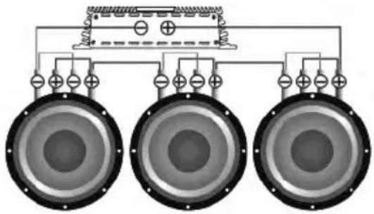
natural_image
Pure electrical circuit lines without any symbols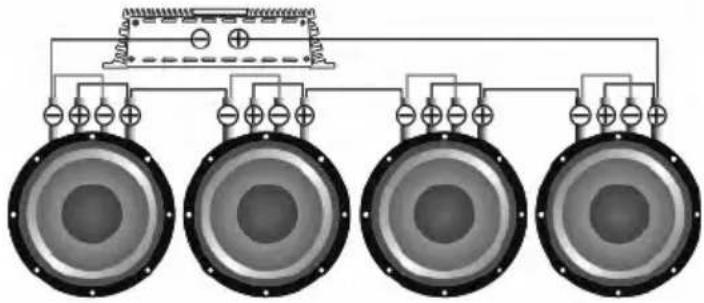
natural_image
Diagram of four speakers arranged in a row with power lines and grounding symbols (no text or labels)natural_image
Pure electrical circuit lines without any symbols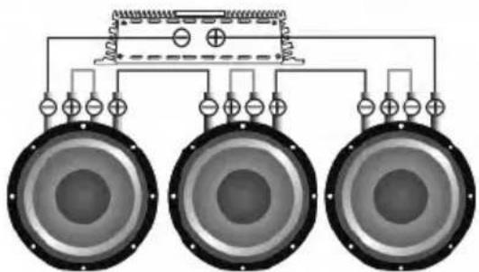
natural_image
Pure electrical circuit lines without any symbolsnatural_image
Pure electrical circuit lines without any symbolsnatural_image
Pure electrical circuit lines without any symbols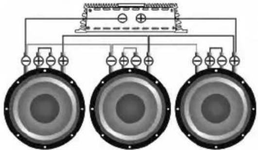
natural_image
Pure electrical circuit lines without any symbols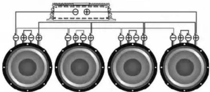
natural_image
Diagram of four speakers arranged in a row with a central speaker block connected to the top panel (no text or symbols)natural_image
Pure electrical circuit lines without any symbolsnatural_image
Pure electrical circuit lines without any symbols
- INTRODUCTION
- SAFETY INSTRUCTIONS
- TYPICAL INSTALLATION SEQUENCE
- CONNECTION METHODS
- SPEAKERS WIRING DIAGRAMS
- SUBWOOFERS WIRING DIAGRAMS
- Serial connection
- Parallel connection
- SCHEMES OF ENABLING THE LOAD OF THE SUBWOOFER
- Voice coils 1+1, 2+2, 4+4 Ohm
- One subwoofer, coils in series
- One subwoofer, coils in parallel
- Subwoofers in series, coils in parallel
- W I R I N G D I A G R A M S
- Remote control
- SELECTION OF THE DIAMETER OF POWER CABLES AND SPEAKER CABLES
- Sel e c tio n o f the di a mete r of th e p o wer c a bles
- SPECIFICATIONS
- POSSIBLE FAULTS AND THEIR SOLUTIONS
- BOX CONTENTS
- W A R R A N T Y A N D M A I N T E N A N C E I N F O
- IN FORMATION ON DISPOSAL OF THE ELECTRICAL AND ELECTRONIC EQUIPMENT (FOR THE EUROPEAN COUNTRIES WITH SEPARATE WASTE COLLECTION)
- СОДЕРЖАНИЕ
Brand : Deaf Bonce
Model : Machete MA-OGO2500.1D Sport
Category : Receiver